digital output module f-dq 8x24vdc/0.5a pp hf … · simatic et 200sp digital output module f-dq...
TRANSCRIPT

___________________
___________________
___________________
___________________
___________________
___________________
___________________
___________________
___________________
___________________
SIMATIC
ET 200SP Digital output module F-DQ 8x24VDC/0.5A PP HF (6ES7136-6DC00-0CA0) Manual
05/2017 A5E38578424-AA
Preface
Documentation guide 1
Product overview 2
Connecting 3
Parameters/address space 4
Applications of the F-I/O module
5
Interrupts/diagnostic messages
6
Technical specifications 7
Response times A
Switching of loads B
Original operating instructions

Siemens AG Division Digital Factory Postfach 48 48 90026 NÜRNBERG GERMANY
A5E38578424-AA Ⓟ 05/2017 Subject to change
Copyright © Siemens AG 2017. All rights reserved
Legal information Warning notice system
This manual contains notices you have to observe in order to ensure your personal safety, as well as to prevent damage to property. The notices referring to your personal safety are highlighted in the manual by a safety alert symbol, notices referring only to property damage have no safety alert symbol. These notices shown below are graded according to the degree of danger.
DANGER indicates that death or severe personal injury will result if proper precautions are not taken.
WARNING indicates that death or severe personal injury may result if proper precautions are not taken.
CAUTION indicates that minor personal injury can result if proper precautions are not taken.
NOTICE indicates that property damage can result if proper precautions are not taken.
If more than one degree of danger is present, the warning notice representing the highest degree of danger will be used. A notice warning of injury to persons with a safety alert symbol may also include a warning relating to property damage.
Qualified Personnel The product/system described in this documentation may be operated only by personnel qualified for the specific task in accordance with the relevant documentation, in particular its warning notices and safety instructions. Qualified personnel are those who, based on their training and experience, are capable of identifying risks and avoiding potential hazards when working with these products/systems.
Proper use of Siemens products Note the following:
WARNING Siemens products may only be used for the applications described in the catalog and in the relevant technical documentation. If products and components from other manufacturers are used, these must be recommended or approved by Siemens. Proper transport, storage, installation, assembly, commissioning, operation and maintenance are required to ensure that the products operate safely and without any problems. The permissible ambient conditions must be complied with. The information in the relevant documentation must be observed.
Trademarks All names identified by ® are registered trademarks of Siemens AG. The remaining trademarks in this publication may be trademarks whose use by third parties for their own purposes could violate the rights of the owner.
Disclaimer of Liability We have reviewed the contents of this publication to ensure consistency with the hardware and software described. Since variance cannot be precluded entirely, we cannot guarantee full consistency. However, the information in this publication is reviewed regularly and any necessary corrections are included in subsequent editions.
Digital output module F-DQ 8x24VDC/0.5A PP HF (6ES7136-6DC00-0CA0) Manual, 05/2017, A5E38578424-AA 3
Preface
Purpose of the documentation This manual supplements the system manual Distributed I/O System ET 200SP (http://support.automation.siemens.com/WW/view/en/58649293).
Functions that affect the system in general are described in this system manual.
The information in this manual and the system/function manuals provide support when you commission the system.
A description of the F-system SIMATIC Safety can be found in the programming and operating manual SIMATIC Safety – Configuring and Programming (http://support.automation.siemens.com/WW/view/en/54110126).
Conventions CPU: When the term "CPU" is used in the following, it refers to both the CPUs of the S7-1500 automation system as well CPUs / interface modules of the ET 200SP distributed I/O system.
STEP 7: In this documentation, "STEP 7" is used as a synonym for all versions of the configuration and programming software " (STEP 7 TIA Portal)".
Note the following identified notes:
Note
A note includes important information on the product described in the documentation, on handling the product or on the part of the documentation to which you ought to pay special attention.
Standards You can find a dated reference to the respective standards in the certificate (https://support.industry.siemens.com/cs/ww/en/view/57141281) or in the EC Declaration of Conformity (https://support.industry.siemens.com/cs/ww/en/view/71764057) for the F-module.

Preface
Digital output module F-DQ 8x24VDC/0.5A PP HF (6ES7136-6DC00-0CA0) 4 Manual, 05/2017, A5E38578424-AA
Important note for maintaining the operational safety of your system
Note
The operators of systems with safety-related characteristics must adhere to specific operational safety requirements. The supplier is also obliged to comply with special product monitoring measures. Siemens informs system operators in the form of personal notifications about product developments and properties which may be or become important issues in terms of operational safety.
You should subscribe to the corresponding notifications in order to obtain the latest information and to allow you to make any necessary modifications to your system.
Log on to Industry Online Support. Follow the links below and click on "Email on update" on the right-hand side in each case: • SIMATIC S7-300/S7-300F
(https://support.industry.siemens.com/cs/products?pnid=13751&lc=en-WW) • SIMATIC S7-400/S7-400H/S7-400F/FH
(https://support.industry.siemens.com/cs/products?pnid=13828&lc=en-WW) • SIMATIC WinAC RTX (F) (https://support.industry.siemens.com/cs/ww/en/ps/13915) • SIMATIC S7-1500/SIMATIC S7-1500F
(https://support.industry.siemens.com/cs/products?pnid=13716&lc=en-WW) • SIMATIC S7-1200/SIMATIC S7-1200F
(https://support.industry.siemens.com/cs/products?pnid=13683&lc=en-WW) • Distributed I/O (https://support.industry.siemens.com/cs/products?pnid=14029&lc=en-
WW) • STEP 7 (TIA Portal)
(https://support.industry.siemens.com/cs/products?pnid=14340&lc=en-WW)
Security information Siemens provides products and solutions with industrial security functions that support the secure operation of plants, systems, machines and networks. In order to protect plants, systems, machines and networks against cyber threats, it is necessary to implement – and continuously maintain – a holistic, state-of-the-art industrial security concept. Siemens’ products and solutions only form one element of such a concept. Customer is responsible to prevent unauthorized access to its plants, systems, machines and networks. Systems, machines and components should only be connected to the enterprise network or the internet if and to the extent necessary and with appropriate security measures (e.g. use of firewalls and network segmentation) in place. Additionally, Siemens’ guidance on appropriate security measures should be taken into account. For more information about industrial security, please visit (http://www.siemens.com/industrialsecurity). Siemens’ products and solutions undergo continuous development to make them more secure. Siemens strongly recommends to apply product updates as soon as available and to always use the latest product versions. Use of product versions that are no longer supported, and failure to apply latest updates may increase customer’s exposure to cyber threats. To stay informed about product updates, subscribe to the Siemens Industrial Security RSS Feed under (http://www.siemens.com/industrialsecurity).
Digital output module F-DQ 8x24VDC/0.5A PP HF (6ES7136-6DC00-0CA0) 5 Manual, 05/2017, A5E38578424-AA
Table of contents
Preface ................................................................................................................................................... 3
1 Documentation guide .............................................................................................................................. 7
2 Product overview .................................................................................................................................. 11
2.1 Properties ................................................................................................................................ 11
3 Connecting ........................................................................................................................................... 14
3.1 Wiring and block diagram ....................................................................................................... 14
4 Parameters/address space ................................................................................................................... 16
4.1 Parameters ............................................................................................................................. 16
4.2 Explanation of parameters ...................................................................................................... 18 4.2.1 F-parameters .......................................................................................................................... 18 4.2.1.1 F-parameters .......................................................................................................................... 18 4.2.1.2 Behavior after channel fault .................................................................................................... 18 4.2.1.3 Reintegration after channel fault ............................................................................................. 18 4.2.2 Parameters of the channels .................................................................................................... 19 4.2.2.1 Maximum test period ............................................................................................................... 19 4.2.2.2 Disable dark test for 48 hours ................................................................................................. 19 4.2.2.3 Activated ................................................................................................................................. 20 4.2.2.4 Max. readback time dark test .................................................................................................. 20 4.2.2.5 Max. readback time light test .................................................................................................. 22 4.2.2.6 Activated light test ................................................................................................................... 23 4.2.2.7 Channel failure acknowledge .................................................................................................. 24
4.3 Address space ........................................................................................................................ 24
5 Applications of the F-I/O module ........................................................................................................... 26
5.1 Installation of the ground line between the power supply and the BaseUnit .......................... 26
5.2 Application: Wiring a load to each digital output ..................................................................... 27
5.3 Application: Wiring two loads in parallel to each digital output ............................................... 29
5.4 Application: Connection of a fail-safe digital input to each digital output ................................ 31
5.5 Application: Connection of the ET 200SP digital output module F-RQ 1x24VDC/24..230VAC/5A (6ES7136-6RA00-0BF0) .............................................................. 35
6 Interrupts/diagnostic messages ............................................................................................................. 37
6.1 Status and error display .......................................................................................................... 37
6.2 Interrupts ................................................................................................................................. 40
6.3 Diagnostics alarms .................................................................................................................. 42
6.4 Value status ............................................................................................................................ 46
7 Technical specifications ........................................................................................................................ 47

Table of contents
Digital output module F-DQ 8x24VDC/0.5A PP HF (6ES7136-6DC00-0CA0) 6 Manual, 05/2017, A5E38578424-AA
A Response times .................................................................................................................................... 50
B Switching of loads ................................................................................................................................. 51
B.1 Connecting capacitive loads .................................................................................................. 51
B.2 Switching of inductive loads ................................................................................................... 53

Digital output module F-DQ 8x24VDC/0.5A PP HF (6ES7136-6DC00-0CA0) 7 Manual, 05/2017, A5E38578424-AA
Documentation guide 1
The documentation for the SIMATIC ET 200SP distributed I/O system is arranged into three areas. This arrangement enables you to access the specific content you require.
Basic information
The system manual describes in detail the configuration, installation, wiring and commissioning of the SIMATIC ET 200SP. distributed I/O system. The STEP 7 online help supports you in the configuration and programming.
Device information
Product manuals contain a compact description of the module-specific information, such as properties, wiring diagrams, characteristics and technical specifications.

Documentation guide
Digital output module F-DQ 8x24VDC/0.5A PP HF (6ES7136-6DC00-0CA0) 8 Manual, 05/2017, A5E38578424-AA
General information
The function manuals contain detailed descriptions on general topics regarding the SIMATIC ET 200SP distributed I/O system, e.g. diagnostics, communication, Web server, motion control and OPC UA.
You can download the documentation free of charge from the Internet (http://w3.siemens.com/mcms/industrial-automation-systems-simatic/en/manual-overview/tech-doc-et200/Pages/Default.aspx).
Changes and supplements to the manuals are documented in a Product Information.
You can download the product information free of charge from the Internet (https://support.industry.siemens.com/cs/us/en/view/73021864).
Manual Collection ET 200SP The Manual Collection contains the complete documentation on the SIMATIC ET 200SP distributed I/O system gathered together in one file.
You can find the Manual Collection on the Internet (http://support.automation.siemens.com/WW/view/en/84133942).
"mySupport" With "mySupport", your personal workspace, you make the most of your Industry Online Support.
In "mySupport" you can store filters, favorites and tags, request CAx data and put together your personal library in the Documentation area. Furthermore, your data is automatically filled into support requests and you always have an overview of your current requests.
You need to register once to use the full functionality of "mySupport".
You can find "mySupport" in the Internet (https://support.industry.siemens.com/My/ww/en).
"mySupport" - Documentation In the Documentation area of "mySupport", you have the possibility to combine complete manuals or parts of them to make your own manual. You can export the manual in PDF format or in an editable format.
You can find "mySupport" - Documentation in the Internet (http://support.industry.siemens.com/My/ww/en/documentation).

Documentation guide
Digital output module F-DQ 8x24VDC/0.5A PP HF (6ES7136-6DC00-0CA0) Manual, 05/2017, A5E38578424-AA 9
"mySupport" - CAx Data In the CAx Data area of "mySupport", you can have access the latest product data for your CAx or CAe system.
You configure your own download package with a few clicks.
In doing so you can select:
● Product images, 2D dimension drawings, 3D models, internal circuit diagrams, EPLAN macro files
● Manuals, characteristics, operating manuals, certificates
● Product master data
You can find "mySupport" - CAx Data in the Internet (http://support.industry.siemens.com/my/ww/en/CAxOnline).
Application examples The application examples support you with various tools and examples for solving your automation tasks. Solutions are shown in interplay with multiple components in the system - separated from the focus in individual products.
You can find the application examples on the Internet (https://support.industry.siemens.com/sc/ww/en/sc/2054).
TIA Selection Tool With the TIA Selection Tool, you can select, configure and order devices for Totally Integrated Automation (TIA). This tool is the successor of the SIMATIC Selection Tool and combines the known configurators for automation technology into one tool. With the TIA Selection Tool, you can generate a complete order list from your product selection or product configuration.
You can find the TIA Selection Tool on the Internet (http://w3.siemens.com/mcms/topics/en/simatic/tia-selection-tool).

Documentation guide
Digital output module F-DQ 8x24VDC/0.5A PP HF (6ES7136-6DC00-0CA0) 10 Manual, 05/2017, A5E38578424-AA
SIMATIC Automation Tool You can use the SIMATIC Automation Tool to run commissioning and maintenance activities simultaneously on various SIMATIC S7 stations as a bulk operation independently of the TIA Portal.
The SIMATIC Automation Tool provides a multitude of functions:
● Scanning of a PROFINET/Ethernet network and identification of all connected CPUs
● Address assignment (IP, subnet, gateway) and station name (PROFINET device) to a CPU
● Transfer of the data and the programming device/PC time converted to UTC time to the module
● Program download to CPU
● Operating mode switchover RUN/STOP
● Localization of the CPU by means of LED flashing
● Reading out CPU error information
● Reading the CPU diagnostic buffer
● Reset to factory settings
● Updating the firmware of the CPU and connected modules
You can find the SIMATIC Automation Tool on the Internet (https://support.industry.siemens.com/cs/ww/en/view/98161300).
PRONETA With SIEMENS PRONETA (PROFINET network analysis), you analyze the plant network during commissioning. PRONETA features two core functions:
● The topology overview independently scans PROFINET and all connected components.
● The IO check is a fast test of the wiring and the module configuration of a system.
You can find SIEMENS PRONETA on the Internet (https://support.industry.siemens.com/cs/ww/en/view/67460624).

Digital output module F-DQ 8x24VDC/0.5A PP HF (6ES7136-6DC00-0CA0) 11 Manual, 05/2017, A5E38578424-AA
Product overview 2 2.1 Properties
Article number 6ES7136-6DC00-0CA0
View of the module
① Module type and name ⑦ Function class ② LED for diagnostics ⑧ Color identification module type ③ 2D matrix code ⑨ Function and firmware version ④ Connection diagram ⑩ Color code to select the color identification labels ⑤ LEDs for channel status ⑪ Article number ⑥ LED for supply voltage
Figure 2-1 View of the module F-DQ 8x24VDC/0.5A PP HF

Product overview 2.1 Properties
Digital output module F-DQ 8x24VDC/0.5A PP HF (6ES7136-6DC00-0CA0) 12 Manual, 05/2017, A5E38578424-AA
Properties The module has the following technical characteristics:
● Fail-safe digital module
● PROFIsafe
● Supports the "RIOforFA-Safety“ profile on F-CPUs S7-1200/1500.
● PROFIsafe address type 2
● 8 outputs, PP-switching (SIL3/Cat.4/PLe)
● Supply voltage L+
● Output current 0.5 A per output
● Sourcing output (PP-switching)
● Suitable for solenoid valves, DC contactors and signal lamps
● Direct interconnection to inputs of an F-DI possible
● Diagnostics display (DIAG red/green LED)
● Status display for each output (green LED)
● Fault display for each output (red LED)
● Diagnostics
– e.g., short-circuit, channel-specific
– e.g. supply voltage missing, module-specific
● module-wide passivation
The module supports the following functions:
● Firmware update
● I&M identification data
WARNING
The fail-safe performance characteristics in the technical specifications apply for a mission time of 20 years and a repair time of 100 hours. If a repair within 100 hours is not possible, remove the respective module from the BaseUnit or switch off its supply voltage before 100 hours expires. The module switches off independently after the 100 hours have expired.
Follow the repair procedure described in section Diagnostics alarms (Page 42).
Note Cyclic reading of I&M data
Cyclic reading of I&M data can affect the timing of the F-modules. You should therefore avoid short read cycles of less than 500 ms.

Product overview 2.1 Properties
Digital output module F-DQ 8x24VDC/0.5A PP HF (6ES7136-6DC00-0CA0) Manual, 05/2017, A5E38578424-AA 13
Accessories The following accessory must be ordered separately:
● Labeling strips
● Color identification labels
● Reference identification labels
● Shield connection
● Electronic coding element as spare part
You can find additional information about accessories in the Distributed I/O System ET 200SP System Manual (http://support.automation.siemens.com/WW/view/en/58649293).
Passivation of fail-safe outputs over a long period of time
WARNING
Unintentional activation of F-I/O with fail-safe outputs
If an F-I/O with fail-safe outputs is passivated for a period longer than that specified in the safety parameters (> 100 hours) and the fault remains uncorrected, you need to exclude the possibility that the F-I/O can be activated unintentionally by a second fault, and thus put the F-system in a dangerous state.
Even though it is highly unlikely that such hardware faults occur, you must prevent the unintentional activation of F-I/O with fail-safe outputs by using circuit measures or organizational measures.
One possibility is the shutdown of the power supply of the passivated F-I/O within a time period of 100 hours, for example.
The required measures are standardized for plants with product standards.
For all other plants, the plant operator must create a concept for the required measures and have it approved by the inspector.
Property of the individual shutdown of F-modules with fail-safe outputs:
A channel-specific shutdown occurs when a fault is detected. It is also possible to react to critical process states staggered over time or to perform safety-related shutdown of individual outputs.

Digital output module F-DQ 8x24VDC/0.5A PP HF (6ES7136-6DC00-0CA0) Manual, 05/2017, A5E38578424-AA 14
Connecting 3 3.1 Wiring and block diagram
This section provides the block diagram of the F-DQ 8×24VDC/0.5A PP HF F-module with the terminal assignment.
You can find information about the various connection options and their configuration in the section Applications of the F-I/O module (Page 26) or Parameters/address space (Page 16).
You can find additional information about wiring BaseUnits in the Distributed I/O System ET 200SP System Manual (http://support.automation.siemens.com/WW/view/en/58649293).
Note
The load group of the F-module must begin with a light-colored BaseUnit. Keep this in mind as well during configuration.
Note
Make sure that you only use the digital output module with BaseUnit type A0 during commissioning.

Connecting 3.1 Wiring and block diagram
Digital output module F-DQ 8x24VDC/0.5A PP HF (6ES7136-6DC00-0CA0) Manual, 05/2017, A5E38578424-AA 15
Block diagram The following figure shows the wiring of the F-DQ 8×24VDC/0.5A PP HF digital output module on BaseUnit BU type A0 without AUX terminals.
① Backplane bus interface Mn Ground for connection of actuator of channel n. ② Output electronics P1, P2, AUX Internal self-assembling voltage buses
Connection to the left (dark-colored BaseUnit) Connection to the left interrupted (light-colored BaseUnit)
③ Reverse polarity protection DQ-PPn Output bit n, channel n, PP-switching (sourcing output)
④ Color-coded label with color code CC02 (optional)
DIAG LED error of diagnostics (green, red)
⑤ Filter circuit supply voltage (available in light-colored BaseUnit only)
.0 to .7 LED channel status (green)
24 VDC Supply voltage L+ (feed for light-colored BaseUnit only)
F0 to F7 LED channel error (red)
M Supply voltage ground PWR LED Power (green)
Figure 3-1 Block diagram

Digital output module F-DQ 8x24VDC/0.5A PP HF (6ES7136-6DC00-0CA0) 16 Manual, 05/2017, A5E38578424-AA
Parameters/address space 4 4.1 Parameters
Parameters for F-DQ 8x24VDC/0.5A PP HF
WARNING
Diagnostics functions should be activated or deactivated in accordance with the application, see section Applications of the F-I/O module (Page 26).
The following parameters are possible:
Table 4- 1 Configurable parameters
Parameters Value range Default Parameter reassignment in
RUN
Scope
F-parameters: Manual assignment of F-monitoring time
• disable • enable
disabled No Module
F-monitoring time 1 to 65535 ms 150 ms No Module F-source address 1 to 65534 depends on parameter as-
signment of F-CPU No Module
F-destination address 1 to 65534 suggested by F-system No Module F-parameter signature (with-out addresses)
0 to 65535 calculated by F-system No Module
Behavior after channel faults • Passivate the entire module
• Passivate channel
Passivate channel No Module
Reintegration after channel fault
• Adjustable • All channels automati-
cally • All channels manually
(S7-300/400) Adjustable (S7-1200/1500) All channels manually
No Module
F-I/O DB manual number assignment
• disable • enable
disabled No Module
F-I/O DB number — suggested by F-system No Module F-I/O DB name — suggested by F-system No Module
Parameters/address space 4.1 Parameters
Digital output module F-DQ 8x24VDC/0.5A PP HF (6ES7136-6DC00-0CA0) Manual, 05/2017, A5E38578424-AA 17
Parameters Value range Default Parameter reassignment in
RUN
Scope
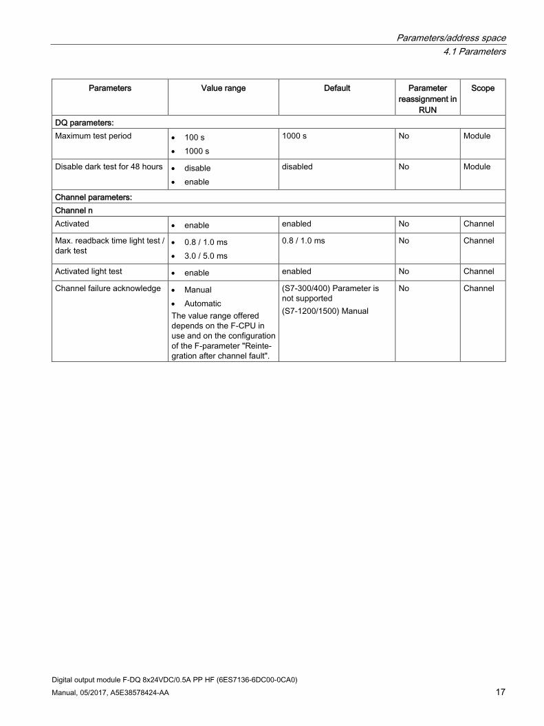
DQ parameters: Maximum test period • 100 s
• 1000 s
1000 s No Module
Disable dark test for 48 hours • disable • enable
disabled No Module
Channel parameters: Channel n Activated • enable enabled No Channel
Max. readback time light test / dark test
• 0.8 / 1.0 ms • 3.0 / 5.0 ms
0.8 / 1.0 ms No Channel
Activated light test • enable enabled No Channel
Channel failure acknowledge • Manual • Automatic The value range offered depends on the F-CPU in use and on the configuration of the F-parameter "Reinte-gration after channel fault".
(S7-300/400) Parameter is not supported (S7-1200/1500) Manual
No Channel
Parameters/address space 4.2 Explanation of parameters
Digital output module F-DQ 8x24VDC/0.5A PP HF (6ES7136-6DC00-0CA0) 18 Manual, 05/2017, A5E38578424-AA
4.2 Explanation of parameters
4.2.1 F-parameters
4.2.1.1 F-parameters You must assign the PROFIsafe address (F-destination address together with F-source address) to the F-module before you put it into operation.
● You define the F-source address using the "Base for PROFIsafe addresses" parameter in the F-CPU.
● An F-destination address unique throughout the CPU is automatically assigned for each F-module. You can manually change the F-destination addresses assigned in the hardware configuration.
You can find information on F-parameters for the F-monitoring time, the PROFIsafe address assignment (F-source address, F-destination address) and the F I/O DB in the manual SIMATIC Safety - Configuring and Programming (http://support.automation.siemens.com/WW/view/en/54110126).
4.2.1.2 Behavior after channel fault This parameter is used to specify whether the entire F-module is passivated or just the faulty channel(s) in the event of channel faults:
● "Passivate the entire module"
● "Passivate channel"
4.2.1.3 Reintegration after channel fault Use this parameter to select how the channels of the fail-safe module are reintegrated after a fault.
Use in S7-300/400 F-CPUs
This parameter is always set to "Adjustable" when you use the fail-safe module in S7-300/400 F-CPUs.
You make the required setting in the F-I/O DB of the fail-safe module.
Parameters/address space 4.2 Explanation of parameters
Digital output module F-DQ 8x24VDC/0.5A PP HF (6ES7136-6DC00-0CA0) Manual, 05/2017, A5E38578424-AA 19
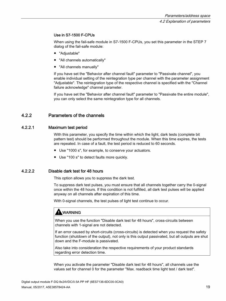
Use in S7-1500 F-CPUs
When using the fail-safe module in S7-1500 F-CPUs, you set this parameter in the STEP 7 dialog of the fail-safe module:
● "Adjustable"
● "All channels automatically"
● "All channels manually"
If you have set the "Behavior after channel fault" parameter to "Passivate channel", you enable individual setting of the reintegration type per channel with the parameter assignment "Adjustable". The reintegration type of the respective channel is specified with the "Channel failure acknowledge" channel parameter.
If you have set the "Behavior after channel fault" parameter to "Passivate the entire module", you can only select the same reintegration type for all channels.
4.2.2 Parameters of the channels
4.2.2.1 Maximum test period With this parameter, you specify the time within which the light, dark tests (complete bit pattern test) should be performed throughout the module. When this time expires, the tests are repeated. In case of a fault, the test period is reduced to 60 seconds.
● Use "1000 s", for example, to conserve your actuators.
● Use "100 s" to detect faults more quickly.
4.2.2.2 Disable dark test for 48 hours This option allows you to suppress the dark test.
To suppress dark test pulses, you must ensure that all channels together carry the 0-signal once within the 48 hours. If this condition is not fulfilled, all dark test pulses will be applied anyway on all channels after expiration of this time.
With 0-signal channels, the test pulses of light test continue to occur.
WARNING
When you use the function "Disable dark test for 48 hours", cross-circuits between channels with 1-signal are not detected.
If an error caused by short-circuits (cross-circuits) is detected when you request the safety function (shutdown of the output), not only is this output passivated, but all outputs are shut down and the F-module is passivated.
Also take into consideration the respective requirements of your product standards regarding error detection time.
When you activate the parameter "Disable dark test for 48 hours", all channels use the values set for channel 0 for the parameter "Max. readback time light test / dark test".

Parameters/address space 4.2 Explanation of parameters
Digital output module F-DQ 8x24VDC/0.5A PP HF (6ES7136-6DC00-0CA0) 20 Manual, 05/2017, A5E38578424-AA
4.2.2.3 Activated The channel is always activated for this F-module.
4.2.2.4 Max. readback time dark test
Function Dark tests are shutdown tests with bit pattern test.
For a dark test, a test signal is switched to the output channel while the output channel has the 1-signal. This output channel is then briefly disabled (= "dark period") and read back. A sufficiently slow actuator does not respond to this and remains switched on.
① Readback
Figure 4-1 Functional principle of the dark test (PP switching)
This parameter allows you to set the time for the readback.
If the expected signals could not be read back correctly after expiration of the readback time dark test, the output channel is passivated.
No new process values are switched to the output channels while a bit pattern is still active (switch test is carried out). This means that a higher maximum readback time for the dark test increases the reaction time of the F-module.
WARNING
Through the configured readback time dark test, short circuits (cross-circuits) to a signal with a frequency greater than 1/(2 x configured readback time dark test) Hz cannot be recognized (50:50 sampling ratio).
Short-circuits (cross-circuits) to an output of the same module are recognized.
The parameter also has an effect on the short-circuit detection (cross-circuit) with 1-signal when the output signal is changed from "1" to "0" with the safety program.

Parameters/address space 4.2 Explanation of parameters
Digital output module F-DQ 8x24VDC/0.5A PP HF (6ES7136-6DC00-0CA0) Manual, 05/2017, A5E38578424-AA 21
Setting readback time dark test Because the fault reaction time is extended by the length of the readback time dark test, we recommend that you set the readback time dark test as low as possible, but high enough that the output channel is not passivated.
In case of the "Connecting a load per digital output" (Page 27) application, see the warnings and notes in the section describing the application.
To determine the readback time required for your actuator, refer to the diagram in the section Switching capacitive loads (Page 51).
Setting readback time dark test with unknown actuator capacity If the capacity of the actuator is not known, it may be necessary for you to determine the value for the readback time dark test by trial and error. This may also be necessary due to the part variances in the actuator or external influences.
Proceed as follows:
● Set the readback time dark test so that the output channel can be read back correctly but your actuator does not respond yet.
● For verification use a 1-signal with a minimum duration that corresponds to the "Maximum test period".
● If the output channel is passivated sporadically, set a higher value for the maximum readback time dark test.
● If the output channel is passivated, the readback time dark test is too small for a connected capacitive load. The discharge cannot take place during the configured readback time dark test. Increase the readback time dark test.
If you have set the readback time dark test to the maximum value of 5 ms and there is still a passivation of the output channel, there is either an external fault or the connected capacity is outside the permitted range.
To increase availability, we recommend that you maintain an interval to the determined limit for the times.

Parameters/address space 4.2 Explanation of parameters
Digital output module F-DQ 8x24VDC/0.5A PP HF (6ES7136-6DC00-0CA0) 22 Manual, 05/2017, A5E38578424-AA
Test pulses of the dark test The interval between two test pulses is 500 ms.
* Output of test pulses only during test cycle.
Figure 4-2 Test pulses of the dark test
Note
If the dark test detects an error, the affected channel is switched off with the error message "Short circuit to L+", all the other channels with the error message "Safety-related shutoff".
4.2.2.5 Max. readback time light test
Function Short-circuit is detected with a 0-signal at the output.
For a light test, a test signal is switched to the output channel while the output channel has the 0-signal. The output channel is switched on briefly during the light test (= "light period") and read back. A sufficiently slow actuator does not respond to this and remains switched off.
① Readback
Figure 4-3 Functional principle of the light test

Parameters/address space 4.2 Explanation of parameters
Digital output module F-DQ 8x24VDC/0.5A PP HF (6ES7136-6DC00-0CA0) Manual, 05/2017, A5E38578424-AA 23
If the signal was not read back correctly once the maximum readback time light test has expired, the output channel is passivated.
No new process values are switched to the output channels while a bit pattern is still active (switch test is carried out). This means that a higher maximum readback time light test for the light test increases the reaction time of the F-module.
Test pulses of the light test
* Output of test pulses only during test cycle.
Figure 4-4 Test pulses of the light test
A light pulse with the configured duration takes place within the configured maximum test period per output channel.
If a light pulse returns a fault, the same light pulse (which means the same bit pattern) is repeated once after 500 ms. If the fault is still present, the maximum test period is automatically reduced to 60 seconds and a diagnostics alarm is generated. If the fault is no longer present, the output channel is reintegrated after the next fault-free test cycle.
4.2.2.6 Activated light test The light test is always enabled for this F-module.
Parameters/address space 4.3 Address space
Digital output module F-DQ 8x24VDC/0.5A PP HF (6ES7136-6DC00-0CA0) 24 Manual, 05/2017, A5E38578424-AA
4.2.2.7 Channel failure acknowledge
Use in S7-1500 F-CPUs
This parameter is only relevant if the fail-safe module is operated on an S7-1500 F-CPU, and can only be set if the F-parameter "Behavior after channel fault" is set to "Passivate channel" and the F-parameter "Reintegration after channel fault" is set to "Adjustable".
The value of this parameter specifies how the channel should react to a channel fault:
● Manual: A channel failure is reintegrated after manual acknowledgment.
● Automatically: The channel is reintegrated automatically after a channel fault. Manual acknowledgment is not necessary.
Use in S7-300/400 F-CPUs
The value of this parameter is not relevant in the case of operation on S7-300/400 F-CPUs. There you set the corresponding property at the F-I/O DB by means of the ACK_NEC tag.
For detailed information about the F-I/O DB, refer to the SIMATIC Safety – Configuring and Programming (http://support.automation.siemens.com/WW/view/en/54110126) manual.
4.3 Address space
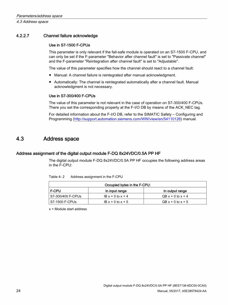
Address assignment of the digital output module F-DQ 8x24VDC/0.5A PP HF The digital output module F-DQ 8x24VDC/0.5A PP HF occupies the following address areas in the F-CPU:
Table 4- 2 Address assignment in the F-CPU
Occupied bytes in the F-CPU: F-CPU In input range In output range S7-300/400 F-CPUs IB x + 0 to x + 4 QB x + 0 to x + 4 S7-1500 F-CPUs IB x + 0 to x + 5 QB x + 0 to x + 5 x = Module start address

Parameters/address space 4.3 Address space
Digital output module F-DQ 8x24VDC/0.5A PP HF (6ES7136-6DC00-0CA0) Manual, 05/2017, A5E38578424-AA 25
Address assignment of the user data and the value status of digital output module F-DQ 8x24VDC/0.5A PP HF
The user data occupy the following addresses in the F-CPU out of all the assigned addresses of the digital output module F-DQ 8x24VDC/0.5A PP HF:
Table 4- 3 Address assignment of user data in the input range
Byte in the F-CPU
Assigned bits in F-CPU per F-module: 7 6 5 4 3 2 1 0
IB x + 0 Value status DQ7
Value status DQ6
Value status DQ5
Value status DQ4
Value status DQ3
Value status DQ2
Value status DQ1
Value status DQ0
x = Module start address
Table 4- 4 Address assignment of user data in the output range
Byte in the F-CPU
Assigned bits in F-CPU per F-module: 7 6 5 4 3 2 1 0
QB x + 0 DQ7 DQ6 DQ5 DQ4 DQ3 DQ2 DQ1 DQ0 x = Module start address
Note
You may only access the addresses occupied by user data and value status.
The other address areas occupied by the F-modules are assigned for functions including safety-related communication between the F-modules and F-CPU in accordance with PROFIsafe.
Additional information For detailed information about F-I/O access, refer to the SIMATIC Safety – Configuring and Programming (http://support.automation.siemens.com/WW/view/en/54110126) manual.
See also Value status (Page 46)

Digital output module F-DQ 8x24VDC/0.5A PP HF (6ES7136-6DC00-0CA0) 26 Manual, 05/2017, A5E38578424-AA
Applications of the F-I/O module 5
You achieve SIL3/Cat.4/PLe with the following applications.
The wiring is performed on the suitable BaseUnit. For more on this, see Connecting section in the system manual Distributed I/O System ET 200SP (http://support.automation.siemens.com/WW/view/en/58649293).
5.1 Installation of the ground line between the power supply and the BaseUnit
Interconnection Achievable fail-safe performance characteristics
Single ground line Redundant ground line Connection of the load to the Mn terminal of the BaseUnit
SIL3/Cat.4/PLe Not required
Connection of the load to the ground of the BaseUnit
SIL3/Cat.3/PLd SIL3/Cat.4/PLe
In case of redundant installation of the ground line between the power supply and the BaseUnits, the ground connection to the BaseUnits must be installed as follows:
● When the fail-safe digital output module F-DQ 8x24VDC/0.5A PP HF is installed on a dark-colored BaseUnit, terminal M of this dark-colored BaseUnit must be additionally connected to the ground of the power supply.
● When the fail-safe digital output module F-DQ 8x24VDC/0.5A PP HF is installed on a light-colored BaseUnit, terminal M of the dark-colored BaseUnit installed to the right of the light-colored BaseUnit must be additionally connected to the ground of the power supply.
WARNING
When connecting the load to the ground of the power supply, you must run two ground lines between the power supply and the BaseUnits for safety reasons to achieve SIL3/Cat.4/PLe. Otherwise, the maximum residual current at signal "0" (specified in the technical specifications) cannot be maintained if a single ground line is interrupted.
See also Connecting (Page 14)

Applications of the F-I/O module 5.2 Application: Wiring a load to each digital output
Digital output module F-DQ 8x24VDC/0.5A PP HF (6ES7136-6DC00-0CA0) Manual, 05/2017, A5E38578424-AA 27
5.2 Application: Wiring a load to each digital output Each of the 8 fail-safe digital outputs consists of two P-switches, which form a PP-switch DQ-PPn. You connect the load between the sourcing output DQ-PPn and ground. The ground may be the internal ground Mn or an external ground. The two P-switches are always activated so that voltage is applied to the load. This circuit achieves SIL3/Cat.4/PLe.
To achieve SIL3/Cat.4/PLe see section Installation of the ground line between the power supply and the BaseUnit (Page 26).
① Backplane bus interface ④ Color-coded label with color code CC02 (optional) ② Output electronics ⑤ Filter circuit supply voltage (available in light-colored
BaseUnit only) ③ Reverse polarity protection
Figure 5-1 Wiring diagram for one relay each to a F-DQ of the digital output module F-DQ 8x24VDC/0.5A PP HF

Applications of the F-I/O module 5.2 Application: Wiring a load to each digital output
Digital output module F-DQ 8x24VDC/0.5A PP HF (6ES7136-6DC00-0CA0) 28 Manual, 05/2017, A5E38578424-AA
WARNING
In order to achieve SIL3/Cat.4/PLe with this wiring, you must install a suitably-qualified actuator, for example in accordance with IEC 60947.
WARNING
The actuator can no longer be shut down if a cross circuit has developed between positive potential (e.g. L+) and DQ-PPn. To prevent cross-circuits between positive potential (e.g. L+) and DQ-PPn, you must route the lines used to connect the actuators in a cross-circuit-proof manner (for example, as separate, sheathed cables or in separate cable ducts).
WARNING
If there is cross-circuit to another output at a non-passivated, switched off output, a brief 1-signal can occur with a duration of 2x max. cycle time (Tcycle) + Max. readback time dark test (Trb).
If there is a cross-circuit between two outputs, the test pulses of light tests of the respective other output are also visible. With a different setting of the "Max. readback time light test" parameter, this can cause cyclically occurring 1-signals that last as long as the longest configured "Max. readback time light test".
If the above mentioned 1-signals dangerously affect the plant when a cross-circuit occurs between outputs, you need to guard against the cross-circuits between the outputs with a cross-circuit-proof installation, for example, with separate sheathed cables or separate cable ducts.

Applications of the F-I/O module 5.3 Application: Wiring two loads in parallel to each digital output
Digital output module F-DQ 8x24VDC/0.5A PP HF (6ES7136-6DC00-0CA0) Manual, 05/2017, A5E38578424-AA 29
5.3 Application: Wiring two loads in parallel to each digital output The ground may be the internal ground Mn or an external ground. This circuit achieves SIL3/Cat.4/PLe.
To achieve SIL3/Cat.4/PLe see section Installation of the ground line between the power supply and the BaseUnit (Page 26).
① Backplane bus interface ④ Color-coded label with color code CC02 (optional) ② Output electronics ⑤ Filter circuit supply voltage (available in light-colored
BaseUnit only) ③ Reverse polarity protection
Figure 5-2 Wiring diagram for two relays in parallel to a F-DQ of the digital output module F-DQ 8x24VDC/0.5A PP HF

Applications of the F-I/O module 5.3 Application: Wiring two loads in parallel to each digital output
Digital output module F-DQ 8x24VDC/0.5A PP HF (6ES7136-6DC00-0CA0) 30 Manual, 05/2017, A5E38578424-AA
WARNING
The actuator can no longer be shut down if a cross circuit has developed between positive potential (e.g. L+) and DQ-PPn. To prevent cross-circuits between positive potential (e.g. L+) and DQ-PPn, you must route the lines used to connect the actuators in a cross-circuit-proof manner (for example, as separate, sheathed cables or in separate cable ducts).
WARNING
If there is cross-circuit to another output at a non-passivated, switched off output, a brief 1-signal can occur with a duration of 2x max. cycle time (Tcycle) + Max. readback time dark test (Trb).
If there is a cross-circuit between two outputs, the test pulses of light tests of the respective other output are also visible. With a different setting of the "Max. readback time light test" parameter, this can cause cyclically occurring 1-signals that last as long as the longest configured "Max. readback time light test".
If the above mentioned 1-signals dangerously affect the plant when a cross-circuit occurs between outputs, you need to guard against the cross-circuits between the outputs with a cross-circuit-proof installation, for example, with separate sheathed cables or separate cable ducts.

Applications of the F-I/O module 5.4 Application: Connection of a fail-safe digital input to each digital output
Digital output module F-DQ 8x24VDC/0.5A PP HF (6ES7136-6DC00-0CA0) Manual, 05/2017, A5E38578424-AA 31
5.4 Application: Connection of a fail-safe digital input to each digital output
Each of the 8 fail-safe digital outputs can be connected to a fail-safe digital input of the type 1, 2 or 3 in accordance with IEC61131-2.
In this application, the input delay of the fail-safe digital input must be set so that the light test and the dark test of the fail-safe digital output do not impair the fail-safe digital input.
You can achieve SIL3/Cat.4/PLe with this circuit.
WARNING
To achieve SIL3/Cat.4/PLe using this wiring, you must use a suitably qualified fail-safe digital input, e.g. ET 200SP F-DI 8x24VDC HF.
Input without ground return To achieve SIL3/Cat.4/PLe see section Installation of the ground line between the power supply and the BaseUnit (Page 26).
If the fail-safe digital output module F-DQ 8x24VDC/0.5A PP HF and the fail-safe digital input module are supplied by different power supply units, the grounds of the two power supply units must be connected to each other.
Figure 5-3 Wiring diagram of an output of the digital output module F-DQ 8x24VDC/0.5A PP HF
with an input of a fail-safe digital input module (without ground return).

Applications of the F-I/O module 5.4 Application: Connection of a fail-safe digital input to each digital output
Digital output module F-DQ 8x24VDC/0.5A PP HF (6ES7136-6DC00-0CA0) 32 Manual, 05/2017, A5E38578424-AA
WARNING
To avoid an impermissible process value at the fail-safe digital input, the wiring must be installed so that an interruption of the connection between the ground of the fail-safe digital output module and the ground of the fail-safe digital input module can be excluded (e.g. redundant lines).
WARNING
In case of a cross-circuit between a positive potential (e.g. L+) and DQ-PPn, a 1-signal is permanently present at the fail-safe digital input. To prevent cross-circuits between positive potential (e.g. L+) and DQ-PPn, you must route the lines used to connect the fail-safe digital inputs in a cross-circuit-proof manner, for example, as separate, sheathed cables or in separate cable ducts.
WARNING
If there is cross-circuit to another output at a non-passivated, switched off output, a brief 1-signal can occur with a duration of 2x max. cycle time (Tcycle) + Max. readback time dark test (Trb).
If there is a cross-circuit between two outputs, the test pulses of light tests of the respective other output are also visible. With a different setting of the "Max. readback time light test" parameter, this can cause cyclically occurring 1-signals that last as long as the longest configured "Max. readback time light test".
If the above mentioned 1-signals dangerously affect the plant when a cross-circuit occurs between outputs, you need to guard against the cross-circuits between the outputs with a cross-circuit-proof installation, for example, with separate sheathed cables or separate cable ducts.
Applications of the F-I/O module 5.4 Application: Connection of a fail-safe digital input to each digital output
Digital output module F-DQ 8x24VDC/0.5A PP HF (6ES7136-6DC00-0CA0) Manual, 05/2017, A5E38578424-AA 33
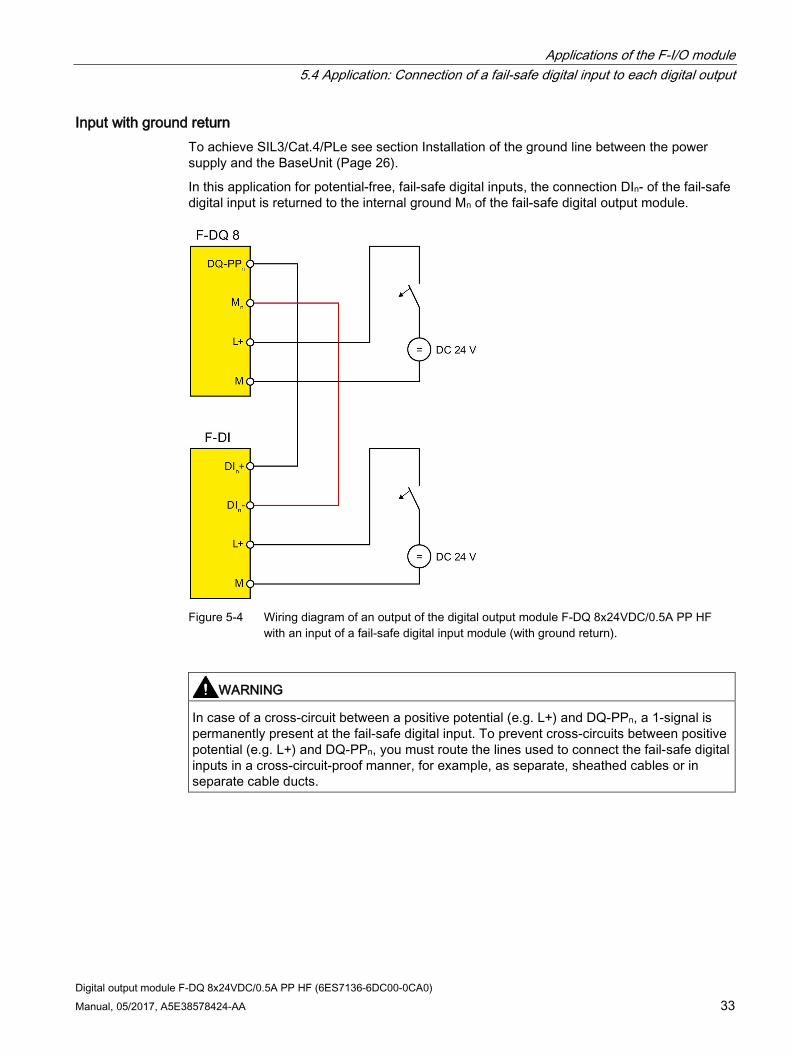
Input with ground return To achieve SIL3/Cat.4/PLe see section Installation of the ground line between the power supply and the BaseUnit (Page 26).
In this application for potential-free, fail-safe digital inputs, the connection DIn- of the fail-safe digital input is returned to the internal ground Mn of the fail-safe digital output module.
Figure 5-4 Wiring diagram of an output of the digital output module F-DQ 8x24VDC/0.5A PP HF
with an input of a fail-safe digital input module (with ground return).
WARNING
In case of a cross-circuit between a positive potential (e.g. L+) and DQ-PPn, a 1-signal is permanently present at the fail-safe digital input. To prevent cross-circuits between positive potential (e.g. L+) and DQ-PPn, you must route the lines used to connect the fail-safe digital inputs in a cross-circuit-proof manner, for example, as separate, sheathed cables or in separate cable ducts.

Applications of the F-I/O module 5.4 Application: Connection of a fail-safe digital input to each digital output
Digital output module F-DQ 8x24VDC/0.5A PP HF (6ES7136-6DC00-0CA0) 34 Manual, 05/2017, A5E38578424-AA
WARNING
If there is cross-circuit to another output at a non-passivated, switched off output, a brief 1-signal can occur with a duration of 2x max. cycle time (Tcycle) + Max. readback time dark test (Trb).
If there is a cross-circuit between two outputs, the test pulses of light tests of the respective other output are also visible. With a different setting of the "Max. readback time light test" parameter, this can cause cyclically occurring 1-signals that last as long as the longest configured "Max. readback time light test".
If the above mentioned 1-signals dangerously affect the plant when a cross-circuit occurs between outputs, you need to guard against the cross-circuits between the outputs with a cross-circuit-proof installation, for example, with separate sheathed cables or separate cable ducts.

Applications of the F-I/O module 5.5 Application: Connection of the ET 200SP digital output module F-RQ 1x24VDC/24..230VAC/5A (6ES7136-6RA00-0BF0)
Digital output module F-DQ 8x24VDC/0.5A PP HF (6ES7136-6DC00-0CA0) Manual, 05/2017, A5E38578424-AA 35
5.5 Application: Connection of the ET 200SP digital output module F-RQ 1x24VDC/24..230VAC/5A (6ES7136-6RA00-0BF0)
You can use any of the 8 fail-safe digital outputs to actuate one or more digital output modules F-RQ 1x24VDC/24..230VAC/5A.
Pay attention to the permitted current for the corresponding output channel and the total current over all outputs at the corresponding ambient temperature.
To achieve SIL3/Cat.4/PLe see section Installation of the ground line between the power supply and the BaseUnit (Page 26).
For the operation of the digital output module F-RQ 1x24VDC/24..230VAC/5A, the use of extended readback times is required (channel parameter Max. readback time light test / dark test with “3.0 / 5.0 ms").
Figure 5-5 Wiring diagram
Note
The output signals "OUT P, OUT M" of the digital output module F-RQ 1x24VDC/24..230VAC/5A are looped through from "IN P, IN M” and should therefore be considered like the output signals of the F-DQ 8x24VDC/0.5A PP HF "DQ-PPn, Mn". For this reason, please observe the wiring rules for the F-DQ 8x24VDC/0.5A PP HF.
WARNING
The digital output module F-RQ 1x24VDC/24..230VAC/5A can no longer be shut down if a cross circuit has developed between positive potential (e.g. L+) and DQ-PPn. To prevent cross-circuits between positive potential (e.g. L+) and DQ-PPn, you must route the lines used to connect the digital output modules F-RQ 1x24VDC/24..230VAC/5A in a cross-circuit-proof manner, e.g. as separate, sheathed cables or in separate cable ducts.

Applications of the F-I/O module 5.5 Application: Connection of the ET 200SP digital output module F-RQ 1x24VDC/24..230VAC/5A (6ES7136-6RA00-0BF0)
Digital output module F-DQ 8x24VDC/0.5A PP HF (6ES7136-6DC00-0CA0) 36 Manual, 05/2017, A5E38578424-AA
WARNING
If there is cross-circuit to another output at a non-passivated, switched off output, a brief 1-signal can occur with a duration of 2x max. cycle time (Tcycle) + Max. readback time dark test (Trb).
If there is a cross-circuit between two outputs, the test pulses of light tests of the respective other output are also visible. With a different setting of the "Max. readback time light test" parameter, this can cause cyclically occurring 1-signals that last as long as the longest configured "Max. readback time light test".
If the above mentioned 1-signals dangerously affect the plant when a cross-circuit occurs between outputs, you need to guard against the cross-circuits between the outputs with a cross-circuit-proof installation, for example, with separate sheathed cables or separate cable ducts.
Digital output module F-DQ 8x24VDC/0.5A PP HF (6ES7136-6DC00-0CA0) Manual, 05/2017, A5E38578424-AA 37
Interrupts/diagnostic messages 6 6.1 Status and error display
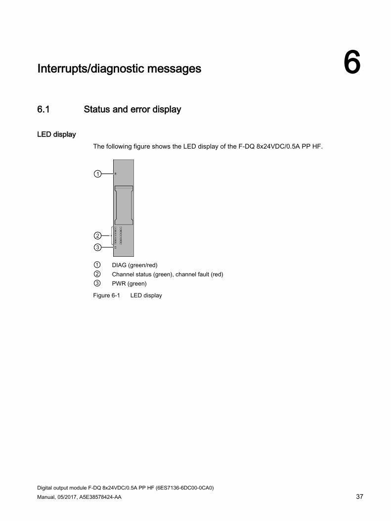
LED display The following figure shows the LED display of the F-DQ 8x24VDC/0.5A PP HF.
① DIAG (green/red) ② Channel status (green), channel fault (red) ③ PWR (green)
Figure 6-1 LED display
Interrupts/diagnostic messages 6.1 Status and error display
Digital output module F-DQ 8x24VDC/0.5A PP HF (6ES7136-6DC00-0CA0) 38 Manual, 05/2017, A5E38578424-AA
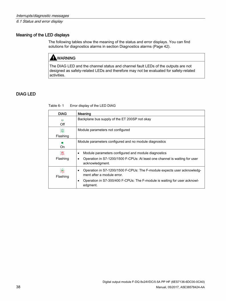
Meaning of the LED displays The following tables show the meaning of the status and error displays. You can find solutions for diagnostics alarms in section Diagnostics alarms (Page 42).
WARNING
The DIAG LED and the channel status and channel fault LEDs of the outputs are not designed as safety-related LEDs and therefore may not be evaluated for safety-related activities.
DIAG LED
Table 6- 1 Error display of the LED DIAG
DIAG Meaning
Off
Backplane bus supply of the ET 200SP not okay
Flashing
Module parameters not configured
On
Module parameters configured and no module diagnostics
Flashing
• Module parameters configured and module diagnostics • Operation in S7-1200/1500 F-CPUs: At least one channel is waiting for user
acknowledgment.
Flashing
• Operation in S7-1200/1500 F-CPUs: The F-module expects user acknowledg-ment after a module error.
• Operation in S7-300/400 F-CPUs: The F-module is waiting for user acknowl-edgment.

Interrupts/diagnostic messages 6.1 Status and error display
Digital output module F-DQ 8x24VDC/0.5A PP HF (6ES7136-6DC00-0CA0) Manual, 05/2017, A5E38578424-AA 39
Channel status/channel fault LED
Table 6- 2 Status display of the LEDs channel status / channel error
Channel status Channel fault Meaning
Off
Off
Process signal = 0 and no channel diagnostics
On
Off
Process signal = 1 and no channel diagnostics
Off
On
Process signal = 0 and channel diagnostics
/ Alternately flashing
• Operation in S7-1200/1500 F-CPUs: At least one channel is waiting for user acknowledgment.
• Operation in S7-300/400 F-CPUs: At least one channel is wait-ing for user acknowledgment.
Channel status/DIAG/channel fault LED
Table 6- 3 Status display of the LEDs channel status / DIAG / channel error
Channel status
DIAG Channel fault
Meaning
Off
Flash-
ing
All On
The PROFIsafe address does not match the configured PROFI-safe address
Flashing
Flash-
ing
Off
Identification of the F-module when assigning the PROFIsafe ad-dress
PWR LED
Table 6- 4 Status display of LED PWR
PWR Meaning
Off
Supply voltage L+ missing
On
Supply voltage L+ available

Interrupts/diagnostic messages 6.2 Interrupts
Digital output module F-DQ 8x24VDC/0.5A PP HF (6ES7136-6DC00-0CA0) 40 Manual, 05/2017, A5E38578424-AA
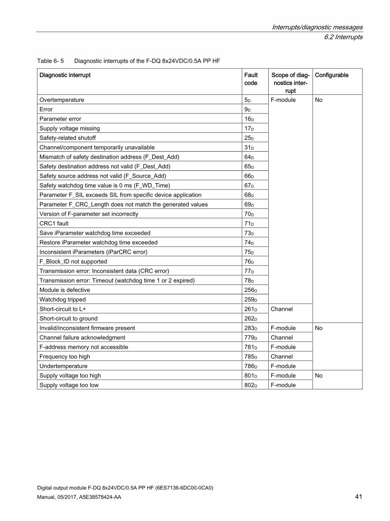
6.2 Interrupts The fail-safe digital output module F-DQ 8x24VDC/0.5A PP HF supports diagnostic interrupts.
Diagnostic interrupts The F-module generates a diagnostic interrupt for each diagnostics alarm described in section Diagnostics alarms (Page 42).
The table below provides an overview of the diagnostic interrupts of the F-module . The diagnostic interrupts are assigned either to one channel or the entire F-module.
WARNING
Before acknowledging the short circuit diagnostics message, correct the respective fault and validate your safety function. In this case, follow the steps described in section Diagnostics alarms (Page 42).
Interrupts/diagnostic messages 6.2 Interrupts
Digital output module F-DQ 8x24VDC/0.5A PP HF (6ES7136-6DC00-0CA0) Manual, 05/2017, A5E38578424-AA 41
Table 6- 5 Diagnostic interrupts of the F-DQ 8x24VDC/0.5A PP HF
Diagnostic interrupt Fault code
Scope of diag-nostics inter-
rupt
Configurable
Overtemperature 5D F-module No Error 9D Parameter error 16D Supply voltage missing 17D Safety-related shutoff 25D Channel/component temporarily unavailable 31D Mismatch of safety destination address (F_Dest_Add) 64D Safety destination address not valid (F_Dest_Add) 65D Safety source address not valid (F_Source_Add) 66D Safety watchdog time value is 0 ms (F_WD_Time) 67D Parameter F_SIL exceeds SIL from specific device application 68D Parameter F_CRC_Length does not match the generated values 69D Version of F-parameter set incorrectly 70D CRC1 fault 71D Save iParameter watchdog time exceeded 73D Restore iParameter watchdog time exceeded 74D Inconsistent iParameters (iParCRC error) 75D F_Block_ID not supported 76D Transmission error: Inconsistent data (CRC error) 77D Transmission error: Timeout (watchdog time 1 or 2 expired) 78D Module is defective 256D Watchdog tripped 259D Short-circuit to L+ 261D Channel Short-circuit to ground 262D Invalid/inconsistent firmware present 283D F-module No Channel failure acknowledgment 779D Channel F-address memory not accessible 781D F-module Frequency too high 785D Channel Undertemperature 786D F-module Supply voltage too high 801D F-module No Supply voltage too low 802D F-module

Interrupts/diagnostic messages 6.3 Diagnostics alarms
Digital output module F-DQ 8x24VDC/0.5A PP HF (6ES7136-6DC00-0CA0) 42 Manual, 05/2017, A5E38578424-AA
6.3 Diagnostics alarms
Diagnostics alarms A diagnostics alarm is generated for each diagnostics event and the F-module flashes the DIAG LED. You can read out the diagnostics alarm, for example, from the diagnostics buffer of the F-CPU. You can evaluate the error codes using the user program.
Note You can connect several actuators per output.
If several actuators are connected to an output, the diagnostics of each actuator affects the other ones.
In other words, a single short-circuit affects multiple actuators.
Once the fault is eliminated, the F-module must be reintegrated in the safety program. For additional information on passivation and reintegration of F-I/O, refer to the SIMATIC Safety – Configuring and Programming (http://support.automation.siemens.com/WW/view/en/54110126) manual.
Table 6- 6 Diagnostics alarms, their meaning and possible remedies
Diagnostics alarm Fault code
Meaning Solution
Overtemperature 5D An excessively high temperature was measured in the F-module.
Operate the F-module within the speci-fied temperature range (see Technical specifications (Page 47)) Once the temperature has been re-duced and returns to the specified range, the F-module must be removed and inserted or the power switched OFF and ON.
Error 9D The F-module has detected an internal error and does not start.
Replace the F-module.
Parameter error 16D Parameter assignment errors include: • The F-module cannot use the param-
eters (unknown, invalid combination, etc.).
• The F-module parameters have not been configured.
Correct the parameter assignment.
Supply voltage missing 17D Missing or insufficient supply voltage L+ • Operate the F-module within the specified supply voltage range.

Interrupts/diagnostic messages 6.3 Diagnostics alarms
Digital output module F-DQ 8x24VDC/0.5A PP HF (6ES7136-6DC00-0CA0) Manual, 05/2017, A5E38578424-AA 43
Diagnostics alarm Fault code
Meaning Solution
Safety-related shutoff 25D For safety purposes, channel was switched off due to an error on another channel. Possible causes: • A short-circuit exists. • The capacitive load is too high.
• Correct the process wiring. • Increase the test times (dark, light).
Channel/component tempo-rarily unavailable
31D The firmware version of the F-module is inconsistent.
Repeat the firmware update.
Mismatch of safety destina-tion address (F_Dest_Add)
64D The firmware of the F-module has de-tected a different F-destination address.
• Check the parameter assignment of the PROFIsafe driver and the PROFIsafe address assigned to the F-module.
• Assign the PROFIsafe address to the F-module (again).
Safety destination address not valid (F_Dest_Add)
65D The firmware of the F-module has de-tected an illegal different F-destination address.
Check the configuration/parameter assignment of the iPar server.
Safety source address not valid (F_Source_Add)
66D The firmware of the F-module has de-tected a different F-source address.
Safety watchdog time value is 0 ms (F_WD_Time)
67D The firmware of the F-module has de-tected an invalid watchdog time.
Parameter F_SIL exceeds SIL from specific device application
68D The firmware of the F-module has de-tected a discrepancy between the SIL setting of the communication and the application.
Parameter F_CRC_Length does not match the generat-ed values
69D The firmware of the F-module has de-tected a discrepancy in the CRC length.
Version of F-parameter set incorrectly
70D The firmware of the F-module has de-tected an incorrect F_Par_Version or an invalid F_Block_ID.
CRC1 fault 71D The firmware of the F-module has de-tected inconsistent F-parameters.
Save iParameter watchdog time exceeded
73D iPar server does not respond to "save IPar" within 4.4 minutes.
Restore iParameter watch-dog time exceeded
74D iPar server does not respond to "restore IPar" within 4.4 minutes.
Check the configuration/parameter assignment of the iPar server.
Inconsistent iParameters (iParCRC error)
75D The firmware of the F-module has de-tected inconsistent iParameters.
Check the parameter assignment.
F_Block_ID not supported 76D The firmware of the F-module has de-tected an incorrect block ID.
Check the parameter assignment of the PROFIsafe driver.

Interrupts/diagnostic messages 6.3 Diagnostics alarms
Digital output module F-DQ 8x24VDC/0.5A PP HF (6ES7136-6DC00-0CA0) 44 Manual, 05/2017, A5E38578424-AA
Diagnostics alarm Fault code
Meaning Solution
Transmission error: Incon-sistent data (CRC error)
77D The firmware of the F-module has de-tected a CRC error. Possible causes: • The communication between the F-
CPU and F-module is disturbed. • Impermissibly high electromagnetic
interference is present. • An error occurred in the sign-of-life
monitoring.
• Check the communication connec-tion between the F-module and F-CPU.
• Eliminate the electromagnetic inter-ference.
• Power switched OFF and ON for station
• Assign the configuration and pa-rameter assignment to the F-module (of the station).
Transmission error: Timeout (watchdog time 1 or 2 ex-pired)
78D The firmware of the F-module has de-tected a timeout. Possible causes: • The F-monitoring time is set incorrect-
ly. • A bus fault is present.
• Check the parameter assignment. • Ensure that communication is func-
tioning correctly.
Module is defective 256D Possible causes: • Impermissibly high electromagnetic
interference is present. • The F-module has detected an inter-
nal error and has reacted in a safety-related manner.
• wrong BaseUnit
• Eliminate the interference. The module must then be pulled and plugged, or the power switched OFF and ON
• If the F-module cannot be put back into operation, consider replacing it.
• Use a BaseUnit of the type A0.
Watchdog tripped 259D Possible causes: • Impermissibly high electromagnetic
interference is present. • The F-module has detected an inter-
nal error and has reacted in a safety-related manner.
• Eliminate the interference. The module must then be pulled and plugged, or the power switched OFF and ON
• If the F-module cannot be put back into operation, consider replacing it.
Short-circuit to L+ 261D Short circuit to L+ can mean: • The output cable is short-circuited to
L+. • The capacitive load between the
channels is too high (for example, due to cable length or load current being too low).
• There is a short circuit between two output channels.
You must eliminate the error within 100 hours; otherwise, the F-module is perma-nently passivated and an acknowledg-ment is no longer possible.
• Correct the process wiring. • Increase the test times (dark, light). • Pay attention to the warnings in
Applications of the F-I/O module (Page 26).

Interrupts/diagnostic messages 6.3 Diagnostics alarms
Digital output module F-DQ 8x24VDC/0.5A PP HF (6ES7136-6DC00-0CA0) Manual, 05/2017, A5E38578424-AA 45
Diagnostics alarm Fault code
Meaning Solution
Short-circuit to ground 262D Short-circuit to ground can mean: • The output cable is short-circuited to
ground. • The output signal is short-circuited to
ground. • The capacitive load is too high. You must eliminate the error within 100 hours; otherwise, the F-module is perma-nently passivated and an acknowledg-ment is no longer possible.
• Correct the process wiring. • Increase the test times (dark, light). • Check the actuator.
Invalid/inconsistent firmware present
283D The firmware is incomplete and/or firm-ware added to the F-module is incompat-ible. This leads to errors or functional limitations when operating the F-module.
• Perform a firmware update for all parts of the F-module and note any error messages.
• Use only firmware versions re-leased for this F-module.
Channel failure acknowl-edgment
779D A channel fault was detected. Confirma-tion is required to enable the channel.
Confirm the channel fault.
F-address memory not ac-cessible
781D The F-source address and F-destination address stored in the coding element cannot be accessed.
Verify that the coding element is pre-sent or replace the coding element.
Frequency too high 785D The maximum switching frequency of the F-module has been exceeded.
Reduce the switching frequency (see Technical specifications (Page 47))
Undertemperature 786D The minimum permissible temperature limit has been violated.
Operate the F-module within the speci-fied temperature range (see Technical specifications (Page 47)) Once the temperature has increased and returns to the specified range, the F-module must be removed and in-serted or the power switched OFF and ON.
Supply voltage too high 801D The supply voltage is too high. Check the supply voltage. Supply voltage too low 802D The supply voltage is too low. Check the supply voltage.
Supply voltage outside the nominal range If the supply voltage L+ is outside the specified value range, the DIAG LED flashes and the module is passivated.
When the voltage is then recovered (level must remain within the specified value for at least 1 minute (see Technical specifications (Page 47) Voltages, Currents, Potentials)), the DIAG LED stops flashing. The module remains passivated.

Interrupts/diagnostic messages 6.4 Value status
Digital output module F-DQ 8x24VDC/0.5A PP HF (6ES7136-6DC00-0CA0) 46 Manual, 05/2017, A5E38578424-AA
Generally applicable information on diagnostics Information on diagnostics that pertains to all fail-safe modules (for example, readout of diagnostics functions or passivation of channels) is available in the SIMATIC Safety – Configuring and Programming (http://support.automation.siemens.com/WW/view/en/54110126) manual.
See also S7 Distributed Safety - Configuring and Programming (https://support.industry.siemens.com/cs/ww/en/view/22099875)
6.4 Value status
Properties In addition to the diagnostics alarm and the status and error display, the F-module provides information about the validity of each input and output signal – the value status. The value status is entered in the process image along with the input signal.
Value status for digital input and output modules The value status is additional binary information of a digital input or output signal. It is entered in the process image of the inputs (PII) at the same time as the process signal. It provides information about the validity of the input or output signal.
The value status is affected by a short-circuit and the plausibility check.
● 1B: A valid process value is output for the channel.
● 0B: A fail-safe value is output for the channel, or the channel is deactivated.
Assignment of the inputs and value status in the PII Each channel of the F-module is assigned a value status in the process image of the inputs. You can find the assignment in section Address space (Page 24).
Reference A detailed description of the evaluation and processing of the respective input signals can be found in the SIMATIC Safety – Configuring and Programming (http://support.automation.siemens.com/WW/view/en/54110126) manual.
Digital output module F-DQ 8x24VDC/0.5A PP HF (6ES7136-6DC00-0CA0) Manual, 05/2017, A5E38578424-AA 47
Technical specifications 7
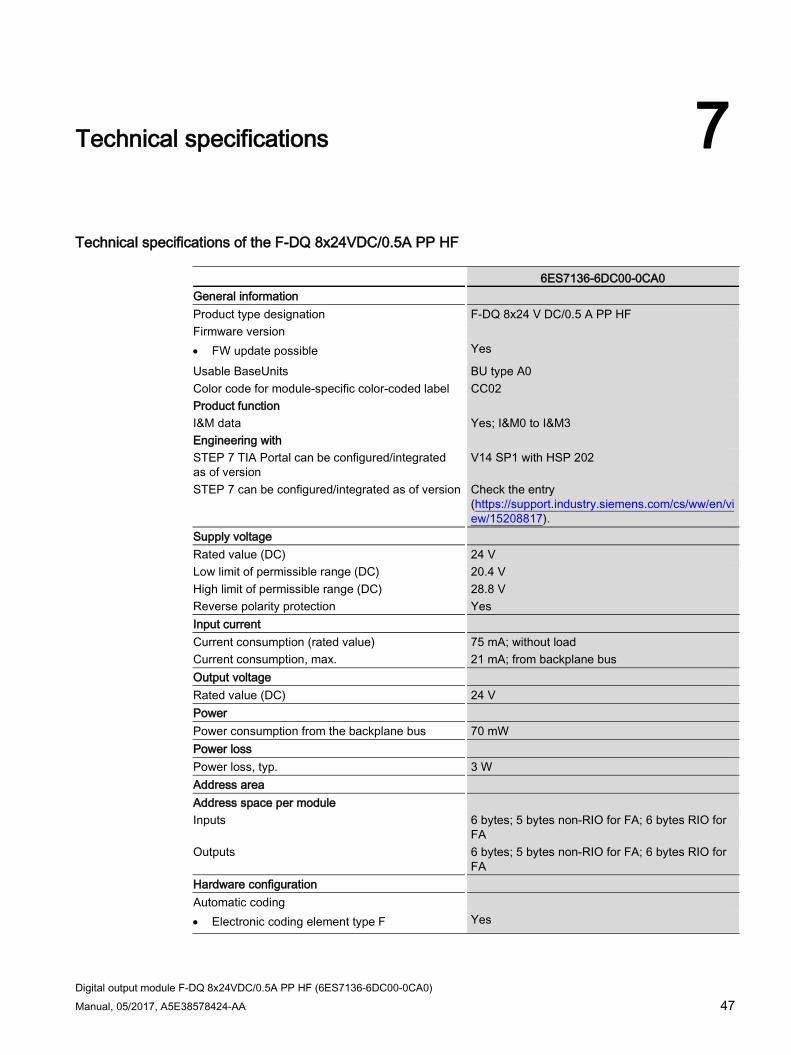
Technical specifications of the F-DQ 8x24VDC/0.5A PP HF
6ES7136-6DC00-0CA0 General information Product type designation F-DQ 8x24 V DC/0.5 A PP HF Firmware version • FW update possible Yes
Usable BaseUnits BU type A0 Color code for module-specific color-coded label CC02 Product function I&M data Yes; I&M0 to I&M3 Engineering with STEP 7 TIA Portal can be configured/integrated as of version
V14 SP1 with HSP 202
STEP 7 can be configured/integrated as of version Check the entry (https://support.industry.siemens.com/cs/ww/en/view/15208817).
Supply voltage Rated value (DC) 24 V Low limit of permissible range (DC) 20.4 V High limit of permissible range (DC) 28.8 V Reverse polarity protection Yes Input current Current consumption (rated value) 75 mA; without load Current consumption, max. 21 mA; from backplane bus Output voltage Rated value (DC) 24 V Power Power consumption from the backplane bus 70 mW Power loss Power loss, typ. 3 W Address area Address space per module Inputs 6 bytes; 5 bytes non-RIO for FA; 6 bytes RIO for
FA Outputs 6 bytes; 5 bytes non-RIO for FA; 6 bytes RIO for
FA Hardware configuration Automatic coding • Electronic coding element type F Yes

Technical specifications
Digital output module F-DQ 8x24VDC/0.5A PP HF (6ES7136-6DC00-0CA0) 48 Manual, 05/2017, A5E38578424-AA
6ES7136-6DC00-0CA0 Digital outputs Number of outputs 8 Short-circuit protection Yes • Response threshold, typ. min. 0.7 A
Wire break detection No Voltage induced on current interruption limited to Typ. -39 V Control of a digital input Yes Switching capacity of outputs With resistive load, max. 0.5 A With lamp load, max. 2 W Load resistance range Low limit 48 Ω High limit 12000 Ω Output voltage For "1" signal, min. 24 V; L+ (-0.5 V) Output current For "1" signal, rated value 0.5 A For "0" signal, residual current, max. 0.5 mA Switching frequency With resistive load, max. 30 Hz; symmetrical With inductive load, max. 0.1 Hz; according to IEC 60947-5-1, DC-13, bal-
anced For capacitive load, max. 2 Hz; balanced With lamp load, max. 10 Hz; symmetrical Total current of outputs Max. current per channel 0.5 A; note derating information in the manual Current per module, max. 3 A; note derating information in the manual Total current of the outputs (per module) Horizontal mounting position • Up to 40 ℃, max. 3 A
• Up to 50 ℃, max. 2.5 A
• Up to 60 ℃, max. 2 A
Vertical mounting position • Up to 50 ℃, max. 2 A
Length of cable shielded, max. 100 m unshielded, max. 100 m Interrupts/diagnostics/status information Diagnostics function Yes, see section "Interrupts/diagnostics alarms"
in the manual Fail-safe values can be switched to No Interrupts Diagnostic interrupt Yes
Technical specifications
Digital output module F-DQ 8x24VDC/0.5A PP HF (6ES7136-6DC00-0CA0) Manual, 05/2017, A5E38578424-AA 49
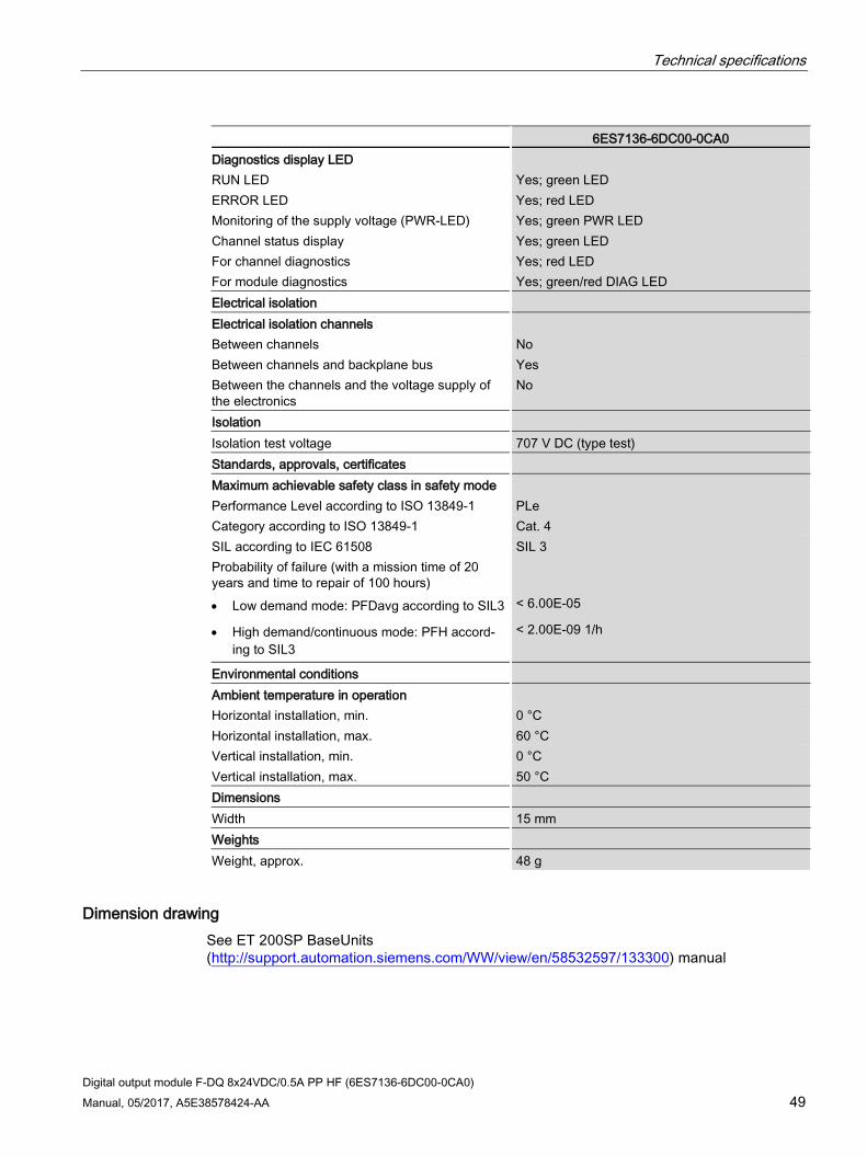
6ES7136-6DC00-0CA0 Diagnostics display LED RUN LED Yes; green LED ERROR LED Yes; red LED Monitoring of the supply voltage (PWR-LED) Yes; green PWR LED Channel status display Yes; green LED For channel diagnostics Yes; red LED For module diagnostics Yes; green/red DIAG LED Electrical isolation Electrical isolation channels Between channels No Between channels and backplane bus Yes Between the channels and the voltage supply of the electronics
No
Isolation Isolation test voltage 707 V DC (type test) Standards, approvals, certificates Maximum achievable safety class in safety mode Performance Level according to ISO 13849-1 PLe Category according to ISO 13849-1 Cat. 4 SIL according to IEC 61508 SIL 3 Probability of failure (with a mission time of 20 years and time to repair of 100 hours)
• Low demand mode: PFDavg according to SIL3 < 6.00E-05
• High demand/continuous mode: PFH accord-ing to SIL3
< 2.00E-09 1/h
Environmental conditions Ambient temperature in operation Horizontal installation, min. 0 °C Horizontal installation, max. 60 °C Vertical installation, min. 0 °C Vertical installation, max. 50 °C Dimensions Width 15 mm Weights Weight, approx. 48 g
Dimension drawing See ET 200SP BaseUnits (http://support.automation.siemens.com/WW/view/en/58532597/133300) manual
Digital output module F-DQ 8x24VDC/0.5A PP HF (6ES7136-6DC00-0CA0) 50 Manual, 05/2017, A5E38578424-AA
Response times A
Introduction You can find the reaction times of the F-DQ 8x24 V DC/0.5 A PP HF digital output module below. The reaction times of the F-DQ 8x24 V DC/0.5 A PP HF digital output module are included in the calculation of the F-system reaction time.
Definition of reaction time for fail-safe digital outputs The reaction time represents the interval between an incoming safety message frame from the backplane bus and the signal change at the digital output.
Times required for the calculation ● Max. cycle time: Tcycle = 8 ms
● Max. acknowledgment time (Device Acknowledgment Time): TDAT = 16 ms
The maximum reaction time in the case of fault (One Fault Delay Time, OFDT) is equivalent to the maximum reaction time with no faults (Worst Case Delay Time, WCDT).
Assign the parameters for maximum readback time dark test (Maximum Readback Time, Trb) and maximum readback time light test (Maximum Readback Time Light Test, Trb_lt) in STEP 7/in the TIA Portal.
Operating mode: Disable dark test for 48 hours – disabled
Maximum reaction time with no faults (Worst Case Delay Time, WCDT)
t <= 4 * Tcycle
Maximum reaction time with detection of a channel fault by readback
t <= 6 * Tcycle + Trb
Maximum reaction time with detection of a channel fault by bit pattern test
t <= 2 * Tcycle + maximum test period
Operating mode: Disable dark test for 48 hours – enabled
Maximum reaction time with no faults (Worst Case Delay Time, WCDT)
t <= 5 * Tcycle + Trb + Trb_lt
Maximum reaction time with detection of a channel fault
A channel fault may not be detected until a 0-1 process value change takes place on the corresponding channel. Please note the restrictions detailed in section Disable dark test for 48 hours (Page 19)
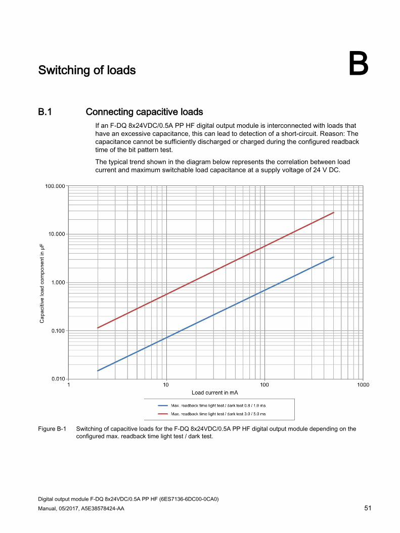
Digital output module F-DQ 8x24VDC/0.5A PP HF (6ES7136-6DC00-0CA0) Manual, 05/2017, A5E38578424-AA 51
Switching of loads B B.1 Connecting capacitive loads
If an F-DQ 8x24VDC/0.5A PP HF digital output module is interconnected with loads that have an excessive capacitance, this can lead to detection of a short-circuit. Reason: The capacitance cannot be sufficiently discharged or charged during the configured readback time of the bit pattern test.
The typical trend shown in the diagram below represents the correlation between load current and maximum switchable load capacitance at a supply voltage of 24 V DC.
Figure B-1 Switching of capacitive loads for the F-DQ 8x24VDC/0.5A PP HF digital output module depending on the
configured max. readback time light test / dark test.

Switching of loads B.1 Connecting capacitive loads
Digital output module F-DQ 8x24VDC/0.5A PP HF (6ES7136-6DC00-0CA0) 52 Manual, 05/2017, A5E38578424-AA
Remedy for detecting a short circuit 1. Determine the load current and capacitance of the load.
2. Locate the operating point in the diagram above.
3. If the operating point is above the trend, select an actuator with higher current consumption so that the new operating point is below the curve.
Example You have configured a maximum readback time light test/dark test of "0.8 / 1.0 ms". You have set the load current to 20 mA and the capacity to 0.2 µF. The operating point is thus outside the range defined by the trend (gray background).
Solution: Select an actuator with higher current consumption. In this example, 40 mA. Alternatively, you can configure the parameter "Max. readback time light test / dark test" with "3.0 / 5.0 ms".

Switching of loads B.2 Switching of inductive loads
Digital output module F-DQ 8x24VDC/0.5A PP HF (6ES7136-6DC00-0CA0) Manual, 05/2017, A5E38578424-AA 53
B.2 Switching of inductive loads
Switching of inductive loads The diagram below shows the maximum permitted inductive loads as a function of the load current and switching frequency.
Figure B-2 Switching of inductive loads for the F-DQ 8x24VDC/0.5A PP HF digital output module depending on the load
current and switching frequency