digital orthoimagery base specification v1digital orthoimagery base specification v1.0 by philip p....
TRANSCRIPT

U.S. Department of the InteriorU.S. Geological Survey
Techniques and Methods 11–B5
National Geospatial Program
Digital Orthoimagery Base Specification V1.0
Chapter 5 ofSection B, U.S. Geological Survey StandardsBook 11, Collection and Delineation of Spatial Data

Cover. St. Louis Zoo, St. Louis, Missouri, East-West Gateway Council of Governments, 2012.
Digital Orthoimagery Base Specification V1.0
By Philip P. Rufe
National Geospatial Program
Techniques and Methods 11–B5
U.S. Department of the InteriorU.S. Geological Survey
Chapter 5 of Section B, U.S. Geological Survey Standards Book 11, Collection and Delineation of Spatial Data

U.S. Department of the InteriorSALLY JEWELL, Secretary
U.S. Geological SurveySuzette M. Kimball, Acting Director
U.S. Geological Survey, Reston, Virginia: 2014
For more information on the USGS—the Federal source for science about the Earth, its natural and living resources, natural hazards, and the environment, visit http://www.usgs.gov or call 1–888–ASK–USGS.
For an overview of USGS information products, including maps, imagery, and publications, visit http://www.usgs.gov/pubprod
To order this and other USGS information products, visit http://store.usgs.gov
Any use of trade, firm, or product names is for descriptive purposes only and does not imply endorsement by the U.S. Government.
Although this information product, for the most part, is in the public domain, it also may contain copyrighted materials as noted in the text. Permission to reproduce copyrighted items must be secured from the copyright owner.
Suggested citation:Rufe, P.P., 2014, Digital orthoimagery base specification V1.0: U.S. Geological Survey Techniques and Methods, book 11, chap. B5, 13 p., http://dx.doi.org/10.3133/tm11B5.
ISSN 2328-7055 (online)
iii
Contents
Introduction.....................................................................................................................................................1Applicability ...........................................................................................................................................1Maintenance Authority ........................................................................................................................1Background............................................................................................................................................1
Project and File Management .....................................................................................................................1Geographic Extent ................................................................................................................................1Non-Image Data ....................................................................................................................................2Use and Distribution Rights .................................................................................................................2
Acquisition and Processing .........................................................................................................................2Acquisition Conditions .........................................................................................................................2Sensor Station Control .........................................................................................................................2Supplemental Ground Control ............................................................................................................3Resolution and Accuracy ....................................................................................................................3
Product Generation .......................................................................................................................................3Aerotriangulation Data ........................................................................................................................3Datums and Coordinates .....................................................................................................................3Digital Orthorectified Image Color .....................................................................................................4Spatial Resolution .................................................................................................................................4Horizontal Accuracy .............................................................................................................................4Product Accuracy Information Reporting ........................................................................................4Digital Orthorectified Image Format ..................................................................................................4Digital Orthorectified Image Tiles.......................................................................................................5Image Mosaicking ................................................................................................................................5Radiometric Resolution ........................................................................................................................5File Naming Convention .......................................................................................................................5Elevation Data........................................................................................................................................6
Metadata .........................................................................................................................................................6Deliverables ....................................................................................................................................................6
Source Imagery .....................................................................................................................................6Digital Orthoimagery and Supporting Data ......................................................................................7
Quality Assessment and Testing by USGS .................................................................................................7Horizontal Accuracy Test ....................................................................................................................7Metadata Adequacy .............................................................................................................................7
Acknowledgments .........................................................................................................................................7References Cited............................................................................................................................................8Appendix 1.....................................................................................................................................................10
Buy-Up Options ...................................................................................................................................10Appendix 2.....................................................................................................................................................11
Film-Based Orthoimagery ..................................................................................................................11Example of Supplemental Forms List ...............................................................................................12

iv
Figures 1. Map showing Universal Transverse Mercator (UTM) and State Plane Zones ..................3
Appendix Figures 2–1. Example of film titling .................................................................................................................12 2–2. Example of project diagram ......................................................................................................13
Tables 1. Product ground pixel resolution and image resolution ..........................................................4 2. Product ground pixel resolution and horizontal accuracy ....................................................4
v
Conversion FactorsInch/Pound to SI
Multiply By To obtain
Length
inch (in.) 2.54 centimeter (cm)inch (in.) 25.4 millimeter (mm)International foot (ft) 0.3048 meter (m)U.S. Survey Foot 0.3048006a meter (m)mile (mi) 1.609 kilometer (km)mile, nautical (nmi) 1.852 kilometer (km)yard (yd) 0.9144 meter (m)
SI to Inch/Pound
Multiply By To obtain
Length
centimeter (cm) 0.3937 inch (in.)millimeter (mm) 0.03937 inch (in.)meter (m) 3.281 International foot (ft) meter (m) 3.28083b U.S. Survey Footkilometer (km) 0.6214 mile (mi)kilometer (km) 0.5400 mile, nautical (nmi) meter (m) 1.094 yard (yd)
a0.30488006 is an approximate conversion factor. Conversions from U.S. Survey Foot should use the exact value of 1200/3937.
b3.28083 is an approximate conversion factor. Conversions to U.S. Survey Foot should use the exact value of 39.39/12.
Vertical coordinate information is referenced to the North American Vertical Datum of 1988 (NAVD 88).
Horizontal coordinate information is referenced to the North American Datum of 1983 (NAD 83).
Elevation, as used in this report, refers to distance above the vertical datum.


Digital Orthoimagery Base Specification V1.0
By Philip P. Rufe
IntroductionThe resolution requirement for orthoimagery in sup-
port of the The National Map of the U.S. Geological Survey (USGS) is 1 meter. However, as the Office of Management and Budget A-16 designated Federal agency responsible for base orthoimagery, the USGS National Geospatial Program (NGP) has developed this base specification to include higher resolution orthoimagery. Many Federal, State, and local pro-grams use high-resolution orthoimagery for various purposes including critical infrastructure management, vector data updates, land-use analysis, natural resource inventory, and extraction of data. The complex nature of large-area ortho-imagery datasets, combined with the broad interest in ortho-imagery, which is of consistent quality and spatial accuracy, requires high-resolution orthoimagery to meet or exceed the format and content outlined in this specification.
The USGS intends to use this specification primarily to create consistency across all NGP funded and managed orthoimagery collections, in particular, collections in support of the National Digital Orthoimagery Program (NDOP). In the absence of other comprehensive specifications or standards, the USGS intends that this specification will, to the highest degree practical, be adopted by other USGS programs and mission areas, and by other Federal agencies.
This base specification, defining minimum parameters for orthoimagery data collection. Local conditions in any given project area, specialized applications for the data, or the preferences of cooperators, may mandate more stringent requirements. The USGS fully supports the acquisition of more detailed, accurate, or value-added data that exceed the base specification outlined herein. A partial list of common “buy-up” options is provided in appendix 1 for those areas and projects that require more stringent or expanded specifications.
Applicability
This document is applicable to orthoimagery data and deliverables funded in whole or in part by the USGS.
Maintenance Authority
The USGS NGP is the maintenance authority for this document.
Background
The USGS has cooperated in the collection of numerous orthoimagery datasets across the Nation for a wide array of applications. A single base set of specifications is used that defines minimum collection parameters and a consistent set of deliverables to facilitate these collections.
This set of specifications for 1-meter or better, high-resolution orthoimagery is based, in part, on a draft high-resolution imagery specification supplied by the Commercial Partnerships Team, National Geospatial Technical Operations Center, NGP, USGS.
It is recognized that the USGS NGP also uses orthoimag-ery for specialized scientific research and other projects whose requirements are incompatible with the provisions of this set of specifications. In such cases, and with properly documented justification supporting the need for the variance, exceptions to any part or all of this set of specifications may be granted by the USGS or one of its partners.
It is conceivable that in some cases, based on specific topography, land cover, intended application, or other factors, the USGS NGP may require specifications more rigorous than those defined in this document.
It is not the intention of the USGS to stifle the develop-ment of the orthoimagery industry, nor to discourage innova-tion within the technology. Technical alternatives to any part of this document may be submitted with any proposal and will be given due professional consideration.
Project and File ManagementThis section provides requirements for project and file
management. It includes specific requirements for document-ing the geographic extent of the project, how to handle non-image data, and use and distribution rights.
Geographic Extent
Each orthoimagery project shall cover the assigned area with a minimum 300 meter (m) or 1,000 foot (ft) buffer on all exterior project edges. Extents shall be computed by projecting the geographic corners and side midpoints to the appropriate projection, then adding the buffer on each side of
2 Digital Orthoimagery Base Specification V1.0
the resulting minimum bounding rectangle (or polygon, if the project has an irregular shape). If a project contains multiple, noncontiguous polygons, the 300 m or 1,000 ft buffer will apply to each polygon in the project.
It is the preference of the USGS for orthoimagery to be divided into 1,500 m by 1,500 m or 5,000 ft by 5,000 ft tiles. Other tile sizes may be acceptable if approved in advance by the USGS. Each image tile will be stored in its own image file. The extent and grid of the image files shall be approved per project area. For the purpose of this and supporting docu-ments, the term dataset will represent the gridded extent of the project area. The term “tile” will be synonymous with “file” and will represent an individual tile used to cover an equal subdivisional portion of the overall extent of the dataset. The relation between dataset and tile/file is one-to-many. The relation between tile and file is one-to-one. An individual tile is composed of one or more image chips. Chips are pieces or snippets of imagery that are used to cover the extent of an image tile. The relation between tile/file and chip is one-to-many.
Non-Image Data
Orthoimagery chips shall not contain any non-image data. Non-image data include items such as photographic frame borders, fiducial marks, artifacts, and titling.
Use and Distribution Rights
All imagery and data delivered under these specifica-tions shall become the property of the U.S. Government. All deliverable data and documentation shall be free from restric-tions regarding use and distribution. Data and documentation delivered under these specifications shall be freely distribut-able by USGS or other government agencies.
Acquisition and ProcessingThe following specifications pertain to the acquisition
and delivery of the required high-resolution natural-color aerial imagery [color-infrared (IR) and 4-band are optional, and may have different specifications]. All USGS acquisitions shall be digital images. Other customers using this set of spec-ifications may, at their discretion, request either film-based photographs or digital images. If film is selected, requirements in appendix 2 should be observed.
Acquisition Conditions
1. Acceptable window—The acceptable window (that is, range of dates) for the acquisition part of this task shall be specific to the project area and as approved by the customer.
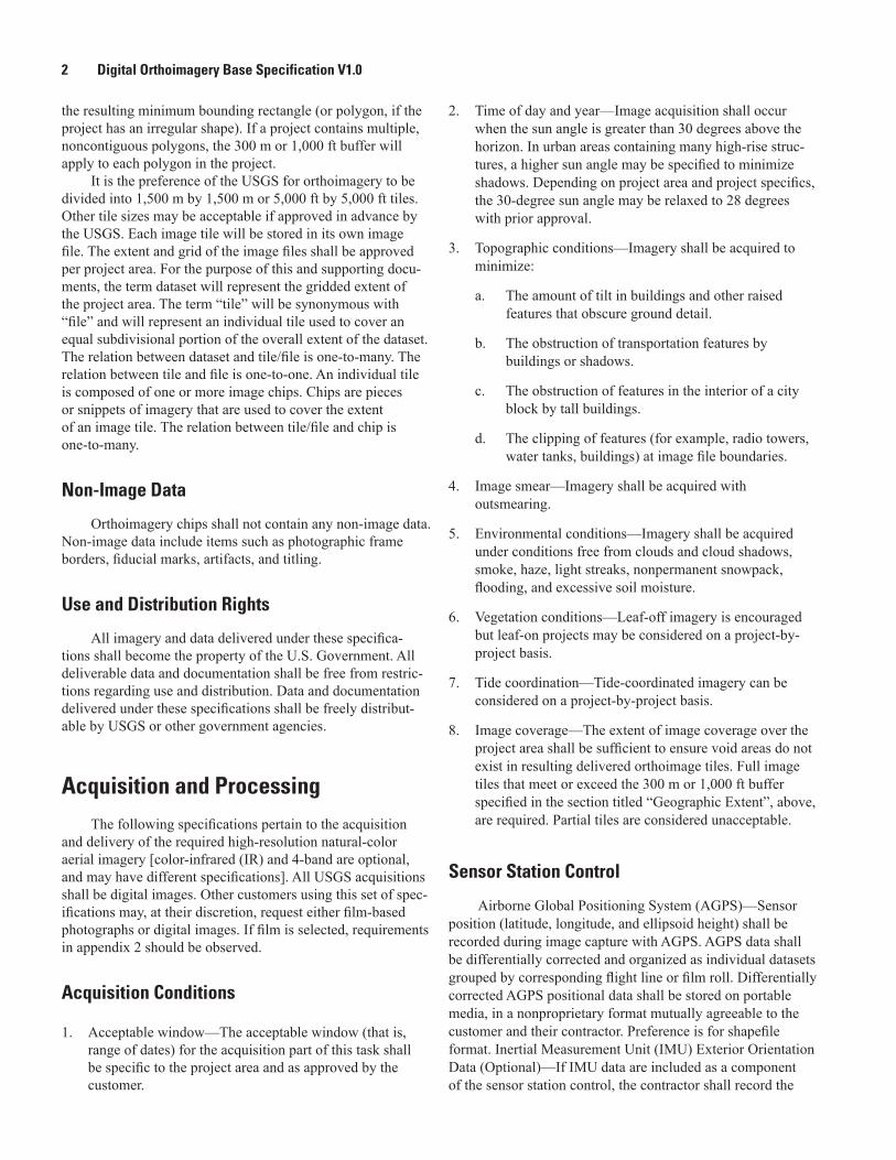
2. Time of day and year—Image acquisition shall occur when the sun angle is greater than 30 degrees above the horizon. In urban areas containing many high-rise struc-tures, a higher sun angle may be specified to minimize shadows. Depending on project area and project specifics, the 30-degree sun angle may be relaxed to 28 degrees with prior approval.
3. Topographic conditions—Imagery shall be acquired to minimize:
a. The amount of tilt in buildings and other raised features that obscure ground detail.
b. The obstruction of transportation features by buildings or shadows.
c. The obstruction of features in the interior of a city block by tall buildings.
d. The clipping of features (for example, radio towers, water tanks, buildings) at image file boundaries.
4. Image smear—Imagery shall be acquired with outsmearing.
5. Environmental conditions—Imagery shall be acquired under conditions free from clouds and cloud shadows, smoke, haze, light streaks, nonpermanent snowpack, flooding, and excessive soil moisture.
6. Vegetation conditions—Leaf-off imagery is encouraged but leaf-on projects may be considered on a project-by-project basis.
7. Tide coordination—Tide-coordinated imagery can be considered on a project-by-project basis.
8. Image coverage—The extent of image coverage over the project area shall be sufficient to ensure void areas do not exist in resulting delivered orthoimage tiles. Full image tiles that meet or exceed the 300 m or 1,000 ft buffer specified in the section titled “Geographic Extent”, above, are required. Partial tiles are considered unacceptable.
Sensor Station Control
Airborne Global Positioning System (AGPS)—Sensor position (latitude, longitude, and ellipsoid height) shall be recorded during image capture with AGPS. AGPS data shall be differentially corrected and organized as individual datasets grouped by corresponding flight line or film roll. Differentially corrected AGPS positional data shall be stored on portable media, in a nonproprietary format mutually agreeable to the customer and their contractor. Preference is for shapefile format. Inertial Measurement Unit (IMU) Exterior Orientation Data (Optional)—If IMU data are included as a component of the sensor station control, the contractor shall record the

Product Generation 3
9
11
11
12 181713
10
14 1615
181213 17
11
10
1614 15
12 1819
13 171614 15
10
15 1614
19
1713 1812
11
11 19
12 18
10
19
1713
20
9
9
161410
20
15
8
19
Universal Transverse Mercator(UTM) zone and number
State Plane zone boundary
State boundary
EXPLANATION
Base modified from Esri, 2013
13
Figure 1. Universal Transverse Mercator (UTM) and State Plane Zones.
sensor attitude during image capture. The IMU data shall be adjusted and organized as individual datasets grouped by cor-responding film roll or flight line (digital imagery).
Supplemental Ground Control
Ground control used to supplement the AGPS positional adjustment, whether conventionally surveyed or surveyed by differential global positioning system (GPS), will conform to conventions and processes to produce orthoimagery that meet required accuracies. Ground control data shall be stored on portable media, in a nonproprietary format mutually agreeable to the customer and their contractor. Preference is for shapefile format. The contractor shall prepare and submit a Supplemen-tal Ground Control report that contains narrative, computa-tions, field notes/photos, and coordinates/elevations for all points surveyed as supplemental ground control.
Resolution and Accuracy
The source imagery shall be of sufficient resolution without downward resampling to support production of digital orthorectified images to the specified ground pixel resolution and to the specifications contained in the next section titled “Product Generation.”
Product GenerationProduct generation includes specifications and parameters
for generating orthoimagery from aerial imagery.
Aerotriangulation Data
Aerotriangulation (AT) data, if used in the orthorectifica-tion process, shall consist of a minimum of exterior orientation parameters, refined image coordinates and adjusted ground coordinates. If AT is performed, the contractor shall provide an AT report including initial approximations and adjusted values for absolute orientation parameters and their residuals. If sur-veyed ground control coordinates are used in the adjustment, then surveyed and adjusted ground control values and their residuals shall also be included.
Datums and Coordinates
All high-resolution orthoimagery shall be projected in the North American Datum of 1983 (NAD 83), using the corresponding native Universal Transverse Mercator (UTM) zone or State Plane zone representing the predominance of the project area (see fig. 1, UTM zones). Coordinates shall be in meters or feet, any adjustments to the datum are to be specified

4 Digital Orthoimagery Base Specification V1.0
on a project by project basis. Data projected in UTM with units of meters are desirable. If feet are used, all references to the linear unit of measure “Feet” or “Foot” must specify either “International” or “U.S. Survey.” If a subsequent adjustment of NAD 83 is used [for example, NAD 83(HARN), NAD 83(NSRS2007), NAD 83(NSRS2011), NAD 83(CORS)], the exact adjustment must be specified. The vertical datum for the supporting elevation data used to create high-resolution digital orthoimagery shall be the North American Vertical Datum of 1988 (NAVD 88). The project will be controlled using the latest available National Geodetic Survey (NGS) control adjustment of the project area, unless an alternative adjust-ment is specifically requested and described by the customer. The data provider will verify the latest available NGS con-trol adjustment(s) pertinent to the geographic extent of the project area.
Digital Orthorectified Image Color
The default type for images is natural color. Color-IR and 4-band may be substituted for natural color as “buy-up” options.
Spatial Resolution
The natural color or four band source imagery shall be of sufficient resolution to support production of digital orthorecti-fied images to the specified ground pixel resolution. Data units of meters are desirable. Orthoimagery produced under this specification shall not be resampled from the original image, original scan or original capture, with resolution greater or less than the numbers shown in table 1.
Table 1. Product ground pixel resolution and image resolution.
[m, meter; ft, foot]
Ground pixel resolution
(GPR)
Original image resolution (maximum)
Original image resolution (minimum)
1.0 m 0.5 m 1.1 m
3.28 ft 1.64 ft 3.6 ft
0.3 m 0.15 m 0.35 m
1 ft 0.5 ft 1.1 ft
0.15 m 0.08 m 0.17 m
0.5 ft 0.25 ft 0.55 ft
0.08 m 0.04 m 0.1 m
0.25 ft 0.125 ft 0.275 ft
Horizontal Accuracy
Orthoimagery accuracy shall be determined using independent ground check points of higher accuracy not used in aerotriangulation or initial georeferencing of the imag-ery. Computed accuracy must meet or exceed the 95 percent National Standard for Spatial Data Accuracy (NSSDA) Con-fidence Interval as shown in table 2 (Federal Geographic Data Committee,1998b).
Table 2. Product ground pixel resolution and horizontal accuracy.
[m, meter; ft, foot; r, radial]
Ground pixel resolution (GPR) Horizontal accuracyr
1.0 m 10.30 m
3.28 ft 33.79 ft
0.3 m 1.52 m
1.0 ft 5.06 ft
0.15 m 0.76 m
0.5 ft 2.5 ft
0.08 m 0.38 m
0.25 ft 1.25 ft
Product Accuracy Information Reporting
Product accuracy information shall be reported according to NSSDA guidelines for tested accuracy, which are available at http://www.fgdc.gov/standards/projects/FGDC-standards-projects/accuracy/part3/chapter3 (Federal Geographic Data Committee,1998b). At a minimum, statements concerning source materials and production processes used must be pro-vided at the project level sufficient to meet the requirements for horizontal accuracy as listed in table 2.
Digital Orthorectified Image Format
The USGS prefers uncompressed data. USGS will accept data in a loss-less compression but reserves the right to obtain and review any compression technique in order to better understand the methodology before making a deci-sion agreeing to its use. Images shall be submitted in ArcGIS readable, GeoTIFF file format, Version 1.8.2, (http://www.remotesensing.org/geotiff/spec/geotiffhome.html) (Ritter and Ruth, 1995) with no internal overviews (pyramid layers). Presence of compression artifacts will be cause for rejection.
Product Generation 5
GeoTIFF files shall include (as a minimum) the following GeoTIFF tags and keys:
• ModelTiepointTag
• ModelPixelScaleTag
or
• ModelTransformation Tag
and
• GTModelTypeGeoKey
• GTRasterTypeGeoKey
• ProjectedCSTypeGeoKey
• PCSCitationGeoKey (or GTCitationGeoKey)
• ProjLinearUnitsGeoKey
Digital Orthorectified Image Tiles
Orthorectified GeoTIFF files shall represent tiles as defined in the project tiling scheme with no chip-overedge. Corner coordinates will be based on the UTM grid or State Plane grid. Image files shall be accompanied by a project index in shapefile format suitable for loading into ArcGIS. The project index shall include image tile boundaries and filenames, and shall be georeferenced in latitude/longitude coordinates.
Image Mosaicking
Orthoimagery may be created using multiple digital images (that is, chips) to produce the final product. Specular reflections and other artifacts should be minimized, especially in developed areas, by patching the area using chips from adjacent overlapping imagery. Above ground features appear-ing in the orthoimage imagery, such as building roof tops, water towers, and radio towers, shall not be clipped at seam-lines or between individual image files.
Radiometry Balance
When a mosaic of two or more images is made, the brightness and color values of the other images will be adjusted to match that of the principal image. The seamlines between the overlapping images will be chosen to minimize tonal variations. Localized adjustment of the brightness and color values will be done to reduce radiometric differences between join areas. Changes in color balance across the project, if they exist, shall be gradual. Abrupt tonal variations between image files are not acceptable.
Edge Matching
Excessive horizontal displacement along seamlines or at image file boundaries is not allowed. The maximum allowable mis-join between transportation features or other well-defined linear features is 3 product Ground Sample Distance (GSD) pixels.
Radiometric Resolution
1. Color imagery—All color imagery shall be no less than 8-bit per band Red, Green, Blue (RGB) image in accor-dance with section 6, RGB Full Color Images, of the Tagged Image File Format TIFFTM Specification, Revi-sion 6 (Adobe Developers Association, 1992) Color-IR and 4-band are optional, and may have different specifica-tions
2. Color Infrared Imagery (CIR)—All color infrared imagery shall be no less than 8-bit per band Near-IR, RG image in accordance with section 6 of TIFFTM Specification, Revi-sion 6 (Adobe Developers Association, 1992).
3. 4-Band Imagery—All imagery that contains both natural color and near-IR shall meet the same requirements as color imagery specified in the Color Infrared Imagery bul-let above and shall have the bands saved in the following order: Red, Green, Blue, and Near-Infrared.
4. Imagery with greater than 8 bits per pixel is allowed providing that the following TIFF tags are included in the image header:
a. SampleFormat,
b. MinSampleValue,
c. MaxSampleValue.
File Naming Convention
For projects in UTM/meters, file names for the orthoim-age files shall be derived from the southwest corner of each image chip and shall be based on the U.S. National Grid, [Fed-eral Geographic Data Committee (FGDC), 2001]. File names will include Grid Zone Designation (GZD), 100,000 meter block designator and X and Y grid coordinates truncated to 100 meters. Supplemental information on the National Grid can be accessed at the FGDC U.S. National Grid website http://www.fgdc.gov/usng.
For projects in State Plane/feet, file names for the orthoimage files shall be derived from the southwest corner of each image chip. The file name will consist of the X and Y State Plane coordinate of the southwest corner, truncated to 1,000 feet.
6 Digital Orthoimagery Base Specification V1.0
Alternative naming conventions may be approved to meet customer requirements.
Elevation Data
Elevation data used during the orthorectification pro-cess shall have sufficient resolution and density to produce orthoimagery that meets the horizontal accuracy requirements outlined in the sections titled “Spatial Resolution” and “Hori-zontal Accuracy.”
MetadataProject metadata describing the orthoimage production
process and tile level metadata for each image file shall be submitted as a deliverable. Federal Geographic Data Commit-tee (FGDC) compliant metadata shall be provided in exten-sible markup language (.xml) format for each orthorectified image file. FGDC compliant metadata for each orthoimage file shall be delivered on portable media. The Web site below contains the files designed to define and support production of FGDC compliant metadata. Download the following files from ftp://ftpext.usgs.gov/pub/cr/mo/rolla/release/xmlinput/.
• XMLInput1_64.zip—Contains an application (XMLIn-put) for creating and editing .xml metadata files. It is not mandatory that this software is used; it is merely available for use. When the zip file is unzipped, it also contains a template (133UAtemplate.xml) and a dtd (csdgm2.dtd) to help with FGDC compliance. The XMLInput.jar is the executable file.
• Help.pdf and XMLInput123.doc—User’s guide for XML Input. Use this guide to install and use XMLIn-put.
• metadata_overview.doc—Additional information about metadata.
DeliverablesThis section describes requirements for orthoimagery
deliverables. These deliverables include the source imagery, digital orthoimagery, and supporting data.
Source Imagery
Sensor Station Control
a. AGPS—Positional data and statistical summary report shall be submitted on portable media, in a nonproprietary format mutually agreeable to the customer and the contractor. In addition, the contrac-tor shall produce a statistical report summarizing the results of the AGPS adjustment.
b. IMU Data—If IMU exterior orientation data are part of the contractor’s technical proposal, the contractor shall submit this sensor orientation data and a statis-tical summary report on portable media, in a nonpro-prietary format mutually agreeable to the customer and the contractor. The contractor also shall produce a statistical report summarizing the overall accuracy of the adjusted IMU data.
Supplemental Ground Control
If used, conventional survey or differentially corrected GPS Ground Control points used to supplement the AGPS positional data shall be delivered on portable media, in a non-proprietary format mutually agreeable to the USGS and the contractor. Preference is for shapefile format.
Flight Diagram
A flight diagram or flight index that illustrates the project area outline, the location of the flight lines and the approxi-mate location of image centers, if relevant, shall be included as a deliverable. This diagram shall be provided in digital shapefile format suitable for loading into ArcGIS.
Independent Check Points
If required or available, independent check points used for accuracy assessment shall be included as a deliverable. These check points shall be delivered on portable media, in a nonproprietary format mutually agreeable to the USGS and the contractor. Preference is for shapefile.
Acknowledgments 7
Digital Orthoimagery and Supporting Data
Aerotriangulation Data
Aerotriangulation data, if used in the orthorectification process, shall be submitted to the USGS in digital format. Aerotriangulation data shall consist of a minimum of exterior orientation parameters, refined image coordinates, adjusted ground coordinates, and a statistical summary report.
Elevation Data
Elevation data created or modified for use in the ortho-rectification process shall be submitted as a deliverable in a nonproprietary format on portable media. Format shall be mutually agreeable between the USGS and contractor. Eleva-tion data provided by the USGS as Government Furnished Material (GFM) does not require submittal, unless said data are modified by the contractor.
Delivery Medium and Format
Digital orthorectified images, in GeoTIFF format, shall be submitted on portable media. Image files shall be accompa-nied by a project index in shapefile format suitable for loading into ArcGIS.
Metadata
Metadata shall be delivered as described in the section titled “Metadata.”
Quality Assessment and Testing by USGS
Quality control will be performed by the USGS to ensure that all processes and procedures used, and metadata produced by the contractor, are adequate to meet all specifications cited as deliverables.
Visual inspection of the data will be performed for the following items:1. Completeness of data to cover the specified geographic
extent, with no omissions or corrupt data.
2. Tonal balancing problems across the project.
3. Extreme tonal or color variation across seamlines.
4. Ground pixel resolution to ensure that orthoimagery meets the specified resolution.
5. Cloud cover, smoke/haze, corrupt data, and void areas.
6. Excessive horizontal displacement along seamlines in images (more than 3 pixels along transportation features, unless project specifications state otherwise).
7. Amount of tilt in buildings and other raised features that obscures ground detail.
8. Transportation features obstructed by buildings or shad-ows.
9. Tall buildings in urban areas that obscure features in the interior of a city block.
10. Clipping of features (for example, radio towers, water tanks, buildings) at image file boundaries.
11. Building/structure, bridge, or road warp that may indicate bad elevation data.
12. Smearing.
13. Evidence of oversaturation or undersaturation as a result of image processing or histogram manipulation.
14. Artifacts caused by image compression.
Horizontal Accuracy Test
Testing is performed on submitted check points. If other suitable control is available, it may also be included in the accuracy test. Check points must be completely independent of control used during aerotriangulation and data production.
Metadata Adequacy
The USGS will verify that accompanying metadata is complete and compliant with FGDC Content Standards for Digital Geospatial Metadata (Federal Geographic Data Committee,1998a).
Acknowledgments
The following U.S. Geological Survey personnel were consulted in the compilation of this document: Dale Benson (retired), Doug Binnie, Russ Caton, Dan Daniels, Bryon Ellingson (retired), Buel (Rusty) Grout, C. Robert Kelly, George Lee, Lori Phillips, Tim Saultz, and Joseph W. Scott (retired).
8 Digital Orthoimagery Base Specification V1.0
References Cited
Adobe Developers Association, 1992, TIFFTM Specification (rev. 6), accessed April 25, 2013, at http://partners.adobe.com/public/developer/en/tiff/TIFF6.pdf.
Federal Geographic Data Committee, 1998a, Content Standard for Digital Geospatial Metadata (revised June 1998): Wash-ington, D.C., Federal Geographic Data Committee, 59 p. plus appendixes, accessed April 25, 2013, at http://www.fgdc.gov/metadata/csdgm/.
Federal Geographic Data Committee, 1998b, Geospatial Positioning Accuracy Standards, Part 3—National Stan-dard for Spatial Data Accuracy (FGDC-STD-007.3-1998): Accessed April 25, 2013, at http://www.fgdc.gov/standards/projects/FGDC-standards-projects/accuracy/part3/index_html/?searchterm=FGDC-STD-007.3-1998.
Federal Geographic Data Committee, 2001, U.S. National Grid Standard (FGDC-STD-011-2001): Reston, Vir-ginia, Federal Geographic Data Committee, 13 p. plus appendixes, accessed April 25, 2013, at http://www.fgdc.gov/standards/projects/FGDC-standards-projects/usng/fgdc_std_011_2001_usng.pdf/view?searchterm=FGDC-STD-011-2001).
Ritter, Niles, Ruth, Mike, 1995, GeoTIFF Format Specifica-tion (ver. 1.8.2), accessed April 25, 2013, at http://www.remotesensing.org/geotiff/spec/geotiffhome.html.

Appendixes
10 Digital Orthoimagery Base Specification V1.0
Appendix 1
Buy-Up Options
Buy-up options are those specifications beyond the mini-mum requirements for orthoimagery outlined in this specifi-cation. The cost of a buy-up option is based on the increased level of effort in addition to the cost for baseline imagery. The following are considered buy-up options:
• Color-infrared—An option where a false color com-posite image is generated by collecting imagery in the green, red, and near-infrared wavelengths and assign-ing blue, green, and red display colors to those relative wavelengths. This may be a no cost option.
• Panchromatic—An option for panchromatic (gray-scale) imagery. This may be a no cost option.
• Four-band—An option where imagery is collected in four bands: blue, green, red, and near-infrared. This may be a no cost option.
• Multi-spectral (five or more bands)—An option where imagery is collected in five or more bands.
• Hyperspectral—An option where imagery is collected in a multitude of narrow spectral ranges.
• Increased horizontal accuracy—Improved accuracy for x and y values.
• Reduced resolution (requires resampling)—Resam-pling collected imagery from 1 foot to 1 meter, and so on.
• Oblique—In nonproprietary format.
Appendixes 11
Appendix 2
Film-Based Orthoimagery
Acquisition and Processing
Film
Contractors may choose a film that processes to either a negative or positive image. If imagery is captured on aerial film for any reason, the following emulsions are preferred.
• Color Positive Film—Kodak Aerochrome III MS Film 2427™, AGFA Aviphot Chrome 200 PE1™ (or equivalent)
• Color Negative Film—AGFA X100 PE1™ film (or equivalent)
• Color Infrared Positive Film—Kodak SO-734 Aero-chrome III Infrared NP™ (or equivalent).
Special Acquisition Conditions
• Calibration: Aerial Film Camera(s) used to acquire project imagery shall have a U.S. Geological Survey (USGS) Camera Calibration Report(s) dated less than 3 years before image acquisition.
Imagery Supplemental Report
The imagery supplemental report shall show the flight line numbers and exposure station or strip numbers. The con-tractor shall use the USGS Aerial Photography Supplemental Report form. An example of this form is included at the end of appendix 2.
Titling
Each exposure shall be clearly titled along the north edge (if flown north-south) or west edge (if flown east-west) of the photograph. Each exposure shall be marked clearly with a numerical abbreviation of the month, day and year of exposure, the number of the roll, the number of the exposure on the roll, the photo scale expressed as a ratio, and the three letter designator (for example, BOS for rolls of film used on a Boston, Massachusetts project) shall be numbered consecu-tively, beginning with number 1; and the exposures on each roll shall be numbered consecutively, beginning with the
number 1. Coarse airborne global positioning system (AGPS) position shall be included in the title as encoded in the camera data chamber. For cameras that do not have camera station positional encoders, the contractor shall manually add the coarse camera position on the opposite edge of the film from the roll exposure designator. An example of titling is included as figure 2 at the end of appendix 2.
Product Generation
Digital Orthorectified Image Characteristics
Image artifacts introduced during the scanning process and appearing in the final orthoimages are unacceptable, except for minimal artifacts falling in noncritical coverage areas. A minimal artifact, for example, would be a small piece of lint appearing in a timbered area.
Deliverables
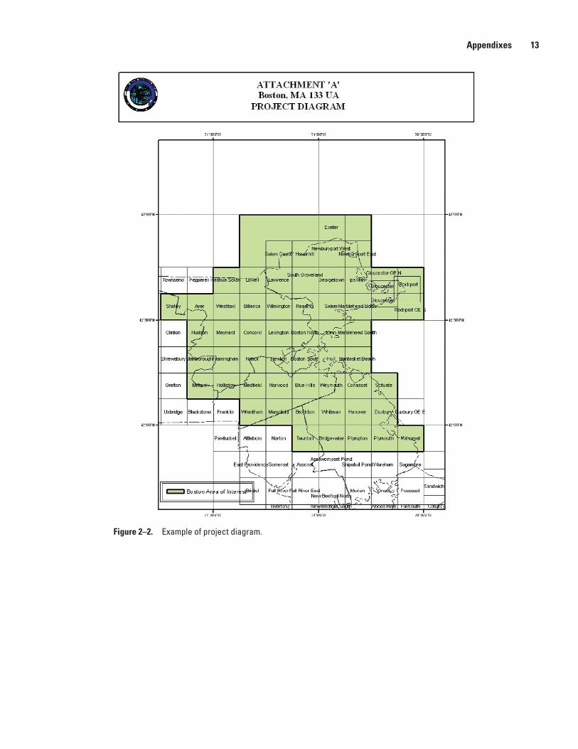
Project Diagram
The contractor shall provide a project diagram delin-eating the project area. An example of a project diagram is included as figure 3 at the end of appendix 2.
Film
The contractor shall provide the original film acquired for the task order. The contractor shall use the standard USGS film can label form included at the end of in appendix 2.
Calibration Reports
If film cameras are used, camera calibration report(s) for aerial camera(s) used shall be included as a deliverable.
Photography and Supplemental Report(s)
A photography supplemental report of all the imagery flown shall be produced for the project. The report shall show the flight line numbers and exposure station or strip numbers, and should agree with the values shown in the flight diagram. The contractor shall use the USGS aerial photography supple-mental report form. An example of this form is included at the end of appendix 2.

12 Digital Orthoimagery Base Specification V1.0
Example of Supplemental Forms List
Attached Supplementary Forms
USGS Film Can Label
2012FilmCanLabelEnabled.pdf
USGS Aerial Photography Supplemental Report
2012AerialPhotographySupplRepEnabled.pdf
USGS Aerial Camera Specifications
2012AerialMappingCameraSpecifications.pdf
Boston MA, 133UA Ortho
Sample Film Titling
(north or west edge)
MO/DY/YR 1:SCALE ROLL-PHOTO# CITY ABR.
COARSE AGPS POSITION*(9X9 FILM)
*For cameras that have camera station position encoders the coarse airborne global positioning system (AGPS) position can be placed along the edge as placed by the camera.
Figure 2–1. Example of film titling.
Appendixes 13
Figure 2–2. Example of project diagram.

Publishing support provided by: Rolla Publishing Service Center
For more information concerning this publication, contact: Director, National Geospatial Technical Operations Center 1400 Independence Road Mail Stop 705 Rolla, MO 65401-2602 (573) 308-3802
Or visit the National Geospatial Technical Operations Center Web site at: http://ngtoc.usgs.gov/


Rufe— D
igital Orthoim
agery Base Specification V1.0—
Techniques and Methods 11–B5
ISSN 2328-7055 (online)
http://dx.doi.org/10.3133/tm11B5