digital optical systems based on coherent and …ocw.umh.es/ingenieria-y-arquitectura/optical...0,...
TRANSCRIPT

Lecture 2: Digital Optical Systems
Optical Communication Systems and Networks
1/
2. Digital Optical Systems based on Coherent and Direct Detection
Optical Communication Systems
and Networks
Lecture 2: Digital Optical Systems
Optical Communication Systems and Networks
2/ Lecture 2: Digital Optical Systems
Optical Communication Systems and Networks
2/
Fiber-Optic Communications Systems Govind P. Agrawal, Chapter 10, pp. 478-512, John Wiley & Sons, 2002, Third Edition.
Optical Fiber Communications. Principles and Practice
John M. Senior. Chapter 12, pp.700-767, Ed. Prentice Hall, 1992, Second Edition,
BIBLIOGRAPHY
12

Lecture 2: Digital Optical Systems
Optical Communication Systems and Networks
3/ Lecture 2: Digital Optical Systems
Optical Communication Systems and Networks
3/
Modulation formats
• Amplitude modulation A0: ASK, Amplitude-shift keying
• Phase modulation 0: PSK, Phase-shift keying
• Frequency modulation 0: FSK, Frequency-shift keying
• Polarization modulation ê: PoSK, information coded by polarization state (not allowed in optical systems based on fiber)
Most commercial systems are based on ASK (These systems are also known as on–off keying, OOK) IM/DD (intensity modulation and Direct Detection)
First Differential PSK (DPSK) are being deployed recently
Optical carrier: E(t) = A0 cos(0t − 0) ê “1” “0” “1” “0” “1” “0”
Electric signal (Bit sequence)
ASK
PSK
FSK
12
Lecture 2: Digital Optical Systems
Optical Communication Systems and Networks
4/ Lecture 2: Digital Optical Systems
Optical Communication Systems and Networks
4/
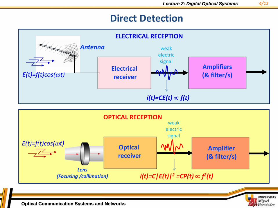
Direct Detection
E(t)=f(t)cos(t)
i(t)=CE(t) f(t)
Electrical receiver
Amplifiers (& filter/s)
Antenna
ELECTRICAL RECEPTION
weak electric signal
OPTICAL RECEPTION
Optical receiver
Amplifier (& filter/s)
weak electric signal
Lens (Focusing /collimation) i(t)=C|E(t)|2 =CP(t) f2(t)
E(t)=f(t)cos(t)
12
Lecture 2: Digital Optical Systems
Optical Communication Systems and Networks
5/ Lecture 2: Digital Optical Systems
Optical Communication Systems and Networks
5/
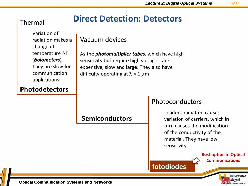
Photodetectors
Thermal
Variation of radiation makes a change of temperature T (bolometers). They are slow for communication applications
Vacuum devices As the photomultiplier tubes, which have high sensitivity but require high voltages, are expensive, slow and large. They also have difficulty operating at > 1 m
Semiconductors
Photoconductors
Incident radiation causes variation of carriers, which in turn causes the modification of the conductivity of the material. They have low sensitivity
fotodiodes
Direct Detection: Detectors
Best option in Optical Communications
12
Lecture 2: Digital Optical Systems
Optical Communication Systems and Networks
6/ Lecture 2: Digital Optical Systems
Optical Communication Systems and Networks
6/
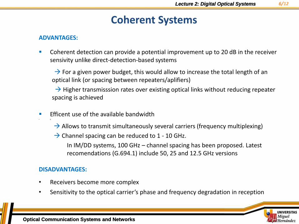
ADVANTAGES:
Coherent detection can provide a potential improvement up to 20 dB in the receiver sensivity unlike direct-detection-based systems
For a given power budget, this would allow to increase the total length of an optical link (or spacing between repeaters/aplifiers)
Higher transmisssion rates over existing optical links without reducing repeater spacing is achieved
Efficent use of the available bandwidth • 6
Allows to transmit simultaneously several carriers (frequency multiplexing)
Channel spacing can be reduced to 1 - 10 GHz.
In IM/DD systems, 100 GHz – channel spacing has been proposed. Latest recomendations (G.694.1) include 50, 25 and 12.5 GHz versions
DISADVANTAGES:
• Receivers become more complex
• Sensitivity to the optical carrier’s phase and frequency degradation in reception
Coherent Systems
12

Lecture 2: Digital Optical Systems
Optical Communication Systems and Networks
7/ Lecture 2: Digital Optical Systems
Optical Communication Systems and Networks
7/
Detector
Electronic driver
Local oscillator
Beam combiner
Electrical bit secuence
Received optical signal (modulated)
Diagram of a Coherent Detection System
CW
12

Lecture 2: Digital Optical Systems
Optical Communication Systems and Networks
8/ Lecture 2: Digital Optical Systems
Optical Communication Systems and Networks
8/
• The optical carrier carries modulated/coded information (phase and/or frequency)
• At receiver: coherent mixing between the incoming signal and optical wave generated by a stable and reduced spectral width local oscillator.
Incoming signal:
Local oscillator:
• Assuming perfect optical mixing, and recalling than optical power is proportional to the square of the electrical field strength, we have :
– if IF = 0, coherent system with homodyne detection
– if IF 0, coherent system with heterodyne detection
)(exp 0 sss tjAE
)(exp LOLOLOOL tjAE
),cos(2)( LOsIFLOsLOs tPPPPtP
LOIFLOLOss KAPKAP 0
22
Coherent Systems
12
Lecture 2: Digital Optical Systems
Optical Communication Systems and Networks
9/ Lecture 2: Digital Optical Systems
Optical Communication Systems and Networks
9/
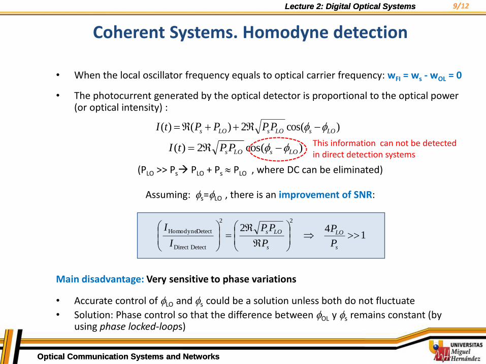
• When the local oscillator frequency equals to optical carrier frequency: wFI = ws - wOL = 0
• The photocurrent generated by the optical detector is proportional to the optical power (or optical intensity) :
(PLO >> Ps PLO + Ps PLO , where DC can be eliminated)
Assuming: s=LO , there is an improvement of SNR:
Main disadvantage: Very sensitive to phase variations
• Accurate control of LO and s could be a solution unless both do not fluctuate
• Solution: Phase control so that the difference between OL y s remains constant (by using phase locked-loops)
)cos(2)()( LOsLOsLOs PPPPtI
)cos(2)( LOsLOsPPtI
142
22
DetectDirect
DetectHomodyne
s
LO
s
LOs
P
P
P
PP
I
I
This information can not be detected in direct detection systems
Coherent Systems. Homodyne detection
12
Lecture 2: Digital Optical Systems
Optical Communication Systems and Networks
10/ Lecture 2: Digital Optical Systems
Optical Communication Systems and Networks
10/
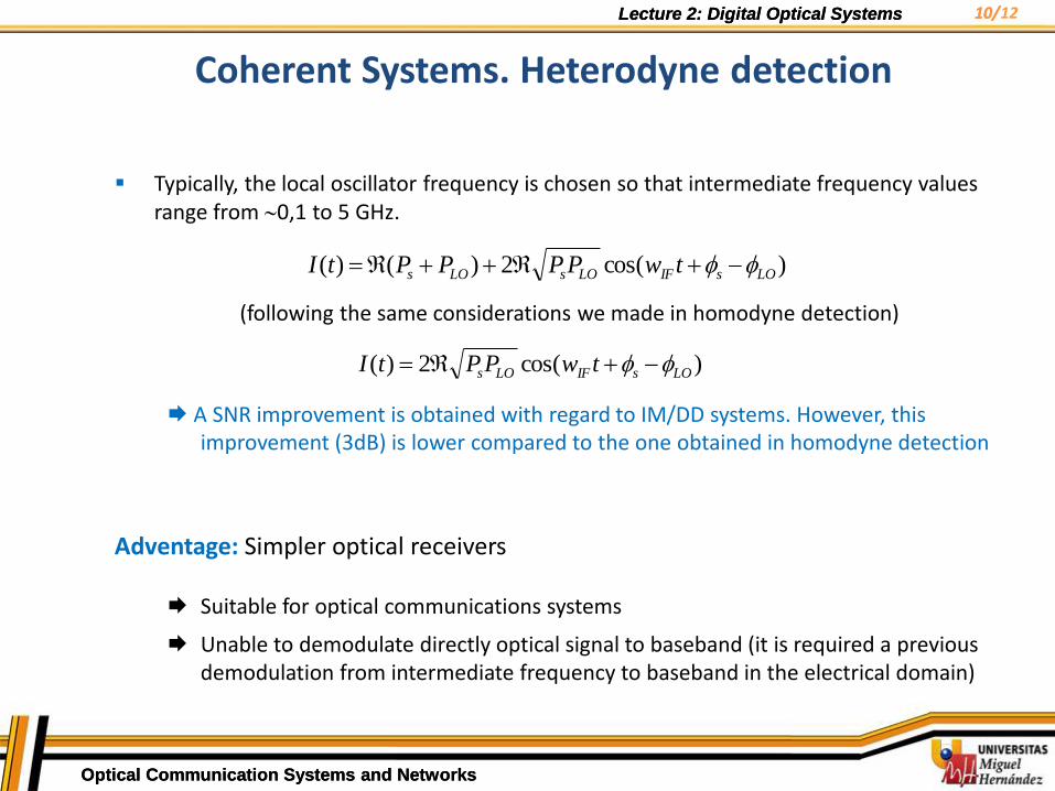
Typically, the local oscillator frequency is chosen so that intermediate frequency values range from 0,1 to 5 GHz.
(following the same considerations we made in homodyne detection)
A SNR improvement is obtained with regard to IM/DD systems. However, this improvement (3dB) is lower compared to the one obtained in homodyne detection
Adventage: Simpler optical receivers
Suitable for optical communications systems
Unable to demodulate directly optical signal to baseband (it is required a previous demodulation from intermediate frequency to baseband in the electrical domain)
)cos(2)()( LOsIFLOsLOs twPPPPtI
)cos(2)( LOsIFLOs twPPtI
Coherent Systems. Heterodyne detection
12
Lecture 2: Digital Optical Systems
Optical Communication Systems and Networks
11/ Lecture 2: Digital Optical Systems
Optical Communication Systems and Networks
11/
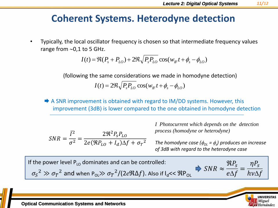
• Typically, the local oscillator frequency is chosen so that intermediate frequency values range from 0,1 to 5 GHz.
(following the same considerations we made in homodyne detection)
A SNR improvement is obtained with regard to IM/DD systems. However, this improvement (3dB) is lower compared to the one obtained in homodyne detection
)cos(2)()( LOsIFLOsLOs twPPPPtI
)cos(2)( LOsIFLOs twPPtI
Coherent Systems. Heterodyne detection
I Photocurrent which depends on the detection
process (homodyne or heterodyne)
The homodyne case (OL = s) produces an increase of 3dB with regard to the heterodyne case
If the power level PLO dominates and can be controlled:
12

Lecture 2: Digital Optical Systems
Optical Communication Systems and Networks
12/ Lecture 2: Digital Optical Systems
Optical Communication Systems and Networks
12/
Diagram of a coherent system based on heterodyne detection
Local Oscillator
Beam combiner
Data out
Incoming optical signal
(modulated)
CW
Bandpass filter
Photodetector
Lowpass filter
subcarrier recovery (IF)
Coherent Systems. Heterodyne detection
12