digital logic - university of florida
TRANSCRIPT

DIGITAL LOGIC PRESENTATION BY: MATTHEW MORAGUEZ, MATTHEW HARWOOD, AADIL VORA,
RUBEN JEAN
FEBRUARY 18, 2015
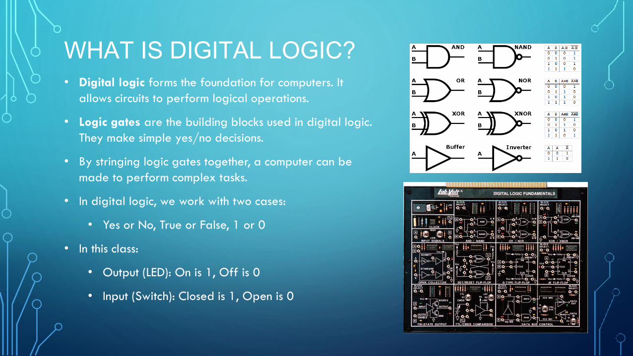
WHAT IS DIGITAL LOGIC? • Digital logic forms the foundation for computers. It
allows circuits to perform logical operations.
• Logic gates are the building blocks used in digital logic.
They make simple yes/no decisions.
• By stringing logic gates together, a computer can be
made to perform complex tasks.
• In digital logic, we work with two cases:
• Yes or No, True or False, 1 or 0
• In this class:
• Output (LED): On is 1, Off is 0
• Input (Switch): Closed is 1, Open is 0

WHAT DO WE DO AS AN ENGINEER?
• Create digital logic circuits that
achieve a desired task.
• Analyze our digital logic circuits to
determine their output.
A one-bit fullbinary adder. This
circuit adds two numbers A and
B and returns the sum S.

LOGIC GATES
The logic gates we will cover today are:
AND (returns true if both inputs are true)
OR (returns true if at least one of the inputs is true)
NOT (returns the opposite of the input)
NOR (returns true if both inputs are false)
NAND (returns false if both inputs are true)
These logic gates form the building blocks of digital logic and
can be strung together to make complex circuits.
The inner workings of logic gates typically consist of
transistors, which are little electrical switches. To make it easier
to visualize, we will use mechanical switches in our circuits.

TRUTH TABLES
A truth table presents the output of a logical operator for
every combination of the input values.
We will use truth tables to explain what each of the logic gates
do.
In this class, we will specify a truth table and give you a chance
to engineer the circuit to act like we want it to.
We will arrange the two switches and the LED so that the
switches open or short the circuit to achieve the desired truth
table.

AND GATE

AND GATE CIRCUIT

OR GATE

OR GATE CIRCUIT

NOT GATE (INVERTER)

NOT GATE CIRCUIT

NOR GATE

NOR GATE CIRCUIT

NAND GATE

NAND GATE CIRCUIT

THANK YOU!