digital key telephone system aria-186/100/ 34e programming ... · programming manual for digital...
TRANSCRIPT
Digital Key Telephone System
Aria-186/100/ 34e
Programming Manual
Admin Programming
Aria Communications Quadrant Business Park 3/15 Pickering Road. MULGRAVE VIC 3170
Programming Manual for Digital Key Telephone System GDK-162/100/34e
Admin Programming
99A Software 1/6/00 A-i
CONTENTS
1. CUSTOMER DATABASE PROGRAMMING ........................................................ 1
1.1 INTRODUCTION ........................................................................................................................ 1
1.2 TO ENTER THE PROGRAMMING MODE ................................................................................ 1
1.3 PERMANENT UPDATE PROCEDURE ..................................................................................... 2
1.4 NUMBERING PLAN ................................................................................................................... 2
1.5 ADMIN PROGRAMMING INDEX ............................................................................................... 7
1.6 DEFAULT VALUES .................................................................................................................. 10
2. PRE-PROGRAMMED DATABASE ..................................................................... 27
2.1 DATABASE INITIALIZATION & NATION ASSIGNMENT (PGM 00) ...................................... 27
2.2 FLEXIBLE NUMBERING PLAN (PGM 01).............................................................................. 30
2.3 SLOT ASSIGNMENT (PGM 02) .............................................................................................. 34
2.4 MSN/SUB ADDRESS TABLE (PGM 03) ................................................................................. 36
2.5 FLEXIBLE DID TABLE (PGM 05) ........................................................................................... 37
2.6 EMERGENCY CALL (PGM 06) ............................................................................................... 39
2.7 NEW LCR (PGM 07) ............................................................................................................... 40
2.8 SYSTEM ATTRIBUTE - IV (PGM 08) ..................................................................................... 44
2.9 ISDN COLP TABLE (PGM 09) ................................................................................................ 47
3. STATION PROGRAM ........................................................................................... 48
3.1 STATION ATTRIBUTE - I (PGM 10) ....................................................................................... 48
3.2 STATION ATTRIBUTE - II (PGM 11) ...................................................................................... 50
3.3 STATION ATTRIBUTE - III (PGM 12) ..................................................................................... 51
3.4 STATION ID (PGM 13) ............................................................................................................ 52
3.5 STATION COS (PGM 14)........................................................................................................ 54
3.6 CO LINE GROUP ACCESS (PGM 15) ................................................................................... 56
3.7 ICM TENANCY GROUP (PGM 16) ......................................................................................... 57
3.8 INTERNAL PAGE ZONE (PGM 17) ........................................................................................ 58
3.9 PRESET CALL FORWARD (PGM 18) .................................................................................... 59
3.10 HOT LINE / WARM LINE (PGM 19) ................................................................................... 60
3.11 SMDR ACCOUNT GROUP (PGM 20) ................................................................................ 61
3.12 STATION ATTRIBUTE - IV (PGM 21) ................................................................................ 62
3.13 CTI STATION ATTRIBUTE (PGM 22) ................................................................................ 63
3.14 ISDN STATION ATTRIBUTE - V (PGM 23) ........................................................................ 64
3.15 STATION ATTRIBUTE - VI (PGM 24) ................................................................................ 67
3.16 LINKED STATION PAIRS (PGM 28) .................................................................................. 69
3.17 FLEX BUTTON ASSIGNMENT (PGM 29) .......................................................................... 70
4. CO LINE PROGRAMMING .................................................................................. 72
4.1 CO LINE ATTRIBUTE – I (PGM 30) ........................................................................................ 72
Programming Manual for Digital Key Telephone System GDK-162/100/34e
Admin Programming
99A Software 1/6/00 A-ii
4.2 CO LINE ATTRIBUTE – II (PGM 31) ...................................................................................... 74
4.3 CO LINE RING ASSIGNMENT (PGM 32) ............................................................................... 75
4.4 CO FLASH TIMER (PGM 33) .................................................................................................. 77
4.5 OPEN LOOP DETECT TIMER (PGM 34) ............................................................................... 77
4.6 TIE LINE ASSIGNMENT (PGM 35) ........................................................................................ 78
4.7 DID LINE ASSIGNMENT (PGM 36) ........................................................................................ 79
4.8 ISDN CO LINE ATTRIBUTES (PGM 37) ................................................................................ 80
4.9 CO LINE ATTRIBUTE – IV (PGM 38) ..................................................................................... 81
4.10 R2 DCOB CO LINE ATTRIBUTE (PGM 39) ....................................................................... 83
5. SYSTEM DATA PROGRAMMING ....................................................................... 85
5.1 SYSTEM ATTRIBUTE - I (PGM 40) ........................................................................................ 85
5.2 SYSTEM ATTRIBUTE - II (PGM 41) ....................................................................................... 86
5.3 SYSTEM ATTRIBUTE - III (PGM 42) ...................................................................................... 88
5.4 SYSTEM TIMERS - I (PGM 43) .............................................................................................. 89
5.5 SYSTEM TIMERS - II (PGM 44) ............................................................................................. 91
5.6 ADMIN PASSWORD (PGM 45) .............................................................................................. 93
5.7 MAIN ATTENDANT STATIONS (PGM 46) ............................................................................. 94
5.8 STATION GROUPS (PGM 47) ................................................................................................ 94
5.9 STATION GROUP ATTRIBUTE (PGM 48) ............................................................................. 96
5.10 EXECUTIVE / SECRETARY PAIRS (PGM 49) ................................................................ 102
5.11 ALARM ATTRIBUTE (PGM 50) ........................................................................................ 102
5.12 EXTERNAL CONTROL CONTACT (PGM 51) ................................................................. 103
5.13 PABX ACCESS CODES (PGM 52) .................................................................................. 105
5.14 SMDR LONG DISTANCE CODES (PGM 53) ................................................................... 106
5.15 AUTHORIZATION CODES (PGM 54) .............................................................................. 106
5.16 DID DIGITS CONVERSION (PGM 55) ............................................................................. 108
5.17 DID/DISA DESTINATION (PGM 56) ................................................................................. 109
5.18 PULSE DIAL SPEED RATIO (PGM 57) ........................................................................... 110
5.19 MODEM ASSIGNMENT (PGM 58) ................................................................................... 111
5.20 SET SYSTEM DATE/TIME (PGM 59) .............................................................................. 112
5.21 LCD DISPLAY MODE (PGM 60) ...................................................................................... 112
5.22 S/W VERSION DISPLAY (PGM 61) ................................................................................. 113
5.23 SMDR ATTRIBUTES - I (PGM 62) ................................................................................... 113
5.24 SMDR ATTRIBUTES - II (PGM 63) .................................................................................. 116
5.25 TIE ROUTING TABLE (PGM 65) ...................................................................................... 117
5.26 SYSTEM GAIN CONTROL (PGM 66) .............................................................................. 118
5.27 SYSTEM SPEED ZONE ACCESS (PGM 67)................................................................... 119
5.28 ACNR TONE CADENCE (PGM 68) .................................................................................. 120
5.29 SYSTEM TONE FREQUENCY (PGM 69) ........................................................................ 121
5.30 WORLD TIME ATTRIBUTE (PGM 71) ............................................................................. 122
5.31 WORLD TIME (PGM 72) ................................................................................................... 123
5.32 VM DIALING TABLE (PGM 73) ........................................................................................ 124
Programming Manual for Digital Key Telephone System GDK-162/100/34e
Admin Programming
99A Software 1/6/00 A-iii
5.33 CO LINE NAME TABLE (PGM 74) ................................................................................... 125
5.34 RING FREQUENCY (PGM 75) ......................................................................................... 126
5.35 DISTINCT RING FREQUENCY (PGM 76) ....................................................................... 127
5.36 DIGITAL CO TX GAIN CONTROL TABLE (PGM 77) ...................................................... 128
5.37 DIGIT INSERTION TABLE (PGM 78) ............................................................................... 129
5.38 CUSTOM CALL ROUTING (PGM 79) .............................................................................. 130
5.39 NATION SPECIFIC PROGRAM (PGM 92) - ONLY FOR AUSTRALIA ............................ 132
5.40 SYSTEM ATTRIBUTES - V (PGM #1) .............................................................................. 133
6. TOLL TABLES .................................................................................................... 136
6.1 TOLL TABLES (PGM 70) ...................................................................................................... 136
6.2 CANNED TOLL TABLES (PGM 64) ...................................................................................... 138
7. DATABASE PRINT (PGM 80) .......................................................................... 139

Programming Manual for Digital Key Telephone System GDK-162/100/34e
Admin Programming
99A Software 1/6/00 A-iv
DIGITAL KEY TELEPHONE SYSTEM
Aria-162/100/34e
******
CONFIDENTIALITY
The information contained in this manual is the property of
Aria Communications Pty. Limited.
The contents of this manual must not be copied, distributed or
made available to any third party without the prior written
consent of Aria Communications Pty. Limited.
"Every effort has been made to ensure that this manual
documents the operation of the Aria-162/100/34e Digital Key
Telephone System.
However, due to the on-going improvement and update of
software, Aria Communications cannot guarantee the accuracy of
printed material after the date of publication, nor can Aria
Communications accept responsibility for errors or omissions.
Revised manuals and update sheets will be published as needed."
Programming Manual for Digital Key Telephone System GDK-162/100/34e
Admin Programming
99A Software 1/6/00 A-1
1. CUSTOMER DATABASE PROGRAMMING
1.1 INTRODUCTION
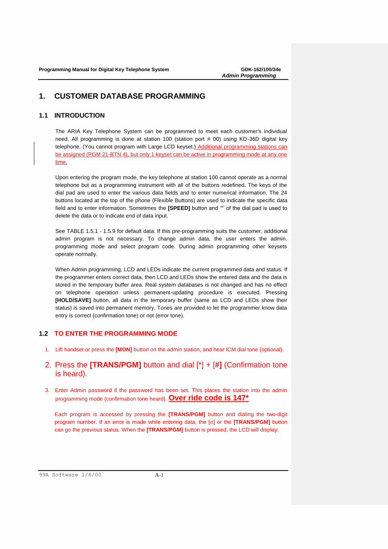
The ARIA Key Telephone System can be programmed to meet each customer's individual
need. All programming is done at station 100 (station port # 00) using KD-36D digital key
telephone. (You cannot program with Large LCD keyset.) Additional programming stations can
be assigned (PGM 21-BTN 4), but only 1 keyset can be active in programming mode at any one
time.
Upon entering the program mode, the key telephone at station 100 cannot operate as a normal
telephone but as a programming instrument with all of the buttons redefined. The keys of the
dial pad are used to enter the various data fields and to enter numerical information. The 24
buttons located at the top of the phone (Flexible Buttons) are used to indicate the specific data
field and to enter information. Sometimes the [SPEED] button and „*‟ of the dial pad is used to
delete the data or to indicate end of data input.
See TABLE 1.5.1 - 1.5.9 for default data. If this pre-programming suits the customer, additional
admin program is not necessary. To change admin data, the user enters the admin.
programming mode and select program code. During admin programming other keysets
operate normally.
When Admin programming, LCD and LEDs indicate the current programmed data and status. If
the programmer enters correct data, then LCD and LEDs show the entered data and the data is
stored in the temporary buffer area. Real system databases is not changed and has no effect
on telephone operation unless permanent-updating procedure is executed. Pressing
[HOLD/SAVE] button, all data in the temporary buffer (same as LCD and LEDs show their
status) is saved into permanent memory. Tones are provided to let the programmer know data
entry is correct (confirmation tone) or not (error tone).
1.2 TO ENTER THE PROGRAMMING MODE
1. Lift handset or press the [MON] button on the admin station, and hear ICM dial tone (optional).
2. Press the [TRANS/PGM] button and dial [*] + [#] (Confirmation tone is heard).
3. Enter Admin password if the password has been set. This places the station into the admin
programming mode (confirmation tone heard). Over ride code is 147*
Each program is accessed by pressing the [TRANS/PGM] button and dialing the two-digit
program number. If an error is made while entering data, the [] or the [TRANS/PGM] button
can go the previous status. When the [TRANS/PGM] button is pressed, the LCD will display;
Programming Manual for Digital Key Telephone System GDK-162/100/34e
Admin Programming
99A Software 1/6/00 A-2
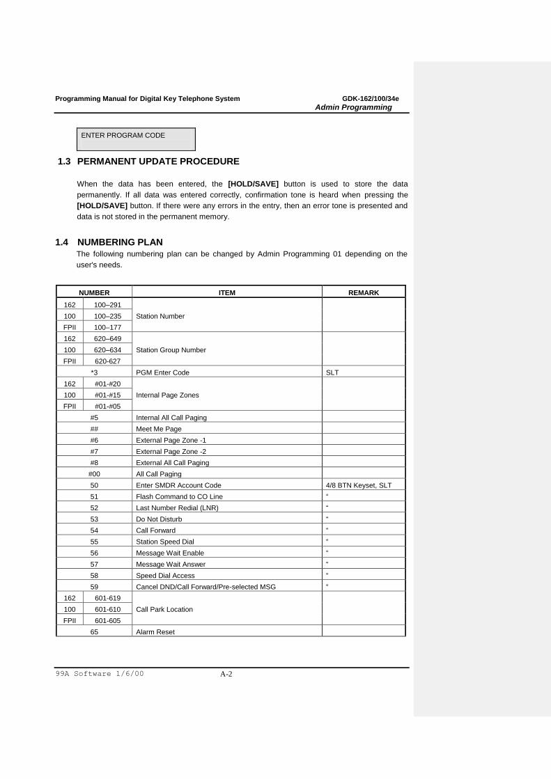
ENTER PROGRAM CODE
1.3 PERMANENT UPDATE PROCEDURE
When the data has been entered, the [HOLD/SAVE] button is used to store the data
permanently. If all data was entered correctly, confirmation tone is heard when pressing the
[HOLD/SAVE] button. If there were any errors in the entry, then an error tone is presented and
data is not stored in the permanent memory.
1.4 NUMBERING PLAN
The following numbering plan can be changed by Admin Programming 01 depending on the
user's needs.
NUMBER ITEM REMARK
162 100–291
Station Number 100 100–235
FPII 100–177
162 620–649
Station Group Number 100 620–634
FPII 620-627
*3 PGM Enter Code SLT
162 #01-#20
Internal Page Zones 100 #01-#15
FPII #01-#05
#5 Internal All Call Paging
## Meet Me Page
#6 External Page Zone -1
#7 External Page Zone -2
#8 External All Call Paging
#00 All Call Paging
50 Enter SMDR Account Code 4/8 BTN Keyset, SLT
51 Flash Command to CO Line “
52 Last Number Redial (LNR) “
53 Do Not Disturb “
54 Call Forward “
55 Station Speed Dial “
56 Message Wait Enable “
57 Message Wait Answer “
58 Speed Dial Access “
59 Cancel DND/Call Forward/Pre-selected MSG “
162 601-619
Call Park Location 100 601-610
FPII 601-605
65 Alarm Reset
Programming Manual for Digital Key Telephone System GDK-162/100/34e
Admin Programming
99A Software 1/6/00 A-3

Programming Manual for Digital Key Telephone System GDK-162/100/34e
Admin Programming
99A Software 1/6/00 A-4
NUMBER ITEM REMARK
** Group Call Pick-up
40# DVU – Record User Greeting for Busy Forwarding
40* DVU – Delete User Greeting for Busy Forwarding
400 DVU – Play User Greeting for Busy Forwarding
401 DVU – Time Announcement
402 DVU – Date Announcement
403 DVU – Station Number Announcement
404 DVU – Record User Greeting for No Answer Forwarding
405 DVU – Delete User Greeting for No Answer Forwarding
406 DVU – Play User Greeting for No Answer Forwarding
407 DVU – Station Statuse Announcement
408 DVU – Record Page Announcement
409 DVU – Retrieve Page Announcement (after 4 sec)
77 Universal Night Answer (UNA)
*7XXX Direct Call Pick-up (XXX = Station Number)
162 801-848
CO Group Access 100 801-824
FPII 801-809
162 8801-8896
CO Line Access 100 8801-8848
FPII 8801-8834
89 Tie Routing Access
8## Retrieve Holding CO Group Keyset
162 8#01-8#96
Retrieve Holding CO Line Keyset 100 8#01-8#48
FPII 8#01-8#34
9 Access the first CO line
0 Attendant Call
661 Print SMDR (Station Base) Attendant
662 Print SMDR (Account Group Base) Attendant
663 Delete SMDR (Station Base) Attendant
664 Delete SMDR (Account Group Base) Attendant
665 Display Call Charge on LCD Attendant
666 Abort SMDR Printing Attendant
#*1 Door Open 1
#*2 Door Open 2
#*3 Door Open 3
#*4 Door Open 4
*8 VM Message Wait Enable
*9 VM Message Wait Cancel
[SPEED] + * Last Number Redial
[SPEED] + # Save Number Redial Keyset
[SPEED] + 00-19 Station Speed Dial Access Keyset
Programming Manual for Digital Key Telephone System GDK-162/100/34e
Admin Programming
99A Software 1/6/00 A-5
NUMBER ITEM REMARK
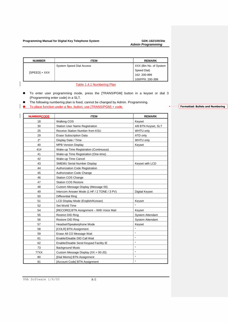
[SPEED] + XXX
System Speed Dial Access XXX (Bin No. of System
Speed Dial)
162: 200-999
100/FPII: 200-399
Table 1.4.1 Numbering Plan
To enter user programming mode, press the [TRANS/PGM] button in a keyset or dial 3
(Programming enter code) in a SLT.
The following numbering plan is fixed, cannot be changed by Admin. Programming.
To place function under a flex. button, use [TRANS/PGM] + code.
NUMBERCODE ITEM REMARK
18 Walking COS Keyset
30 Station User Name Registration 4/8 BTN Keyset, SLT
25 Receive Station Number from KSU WHTU only
29 Erase Subscription Data ATD only
2* Display Date / Time WHTU only
40 MPB Version Display Keyset
41# Wake-up Time Registration (Continuous)
41 Wake-up Time Registration (One-time)
42 Wake-up Time Cancel
43 SMEMU Serial Number Display Keyset with LCD
44 Authorization Code Registration
45 Authorization Code Change
46 Station COS Change
47 Station COS Restore
48 Custom Message Display (Message 00)
49 Intercom Answer Mode (1 HF / 2 TONE / 3 PV) Digital Keyset
50 Differential Ring
51 LCD Display Mode (English/Korean) Keyset
52 Set World Time “
54 [RECORD] BTN Assignment – With Voice Mail Keyset
55 Restrict DID Ring System Attendant
56 Restore DID Ring System Attendant
57 Headset/Speakerphone Mode Keyset
58 [COLR] BTN Assignment “
59 Erase All CO Message Wait “
61 Enable/Disable DID Call Wait “
62 Enable/Disable Send Keypad Facility IE “
73 Background Music "
77XX Custom Message Display (XX = 00-20) "
80 [Dial Memo] BTN Assignment "
81 [Account Code] BTN Assignment "
Formatted: Bullets and Numbering
Programming Manual for Digital Key Telephone System GDK-162/100/34e
Admin Programming
99A Software 1/6/00 A-6
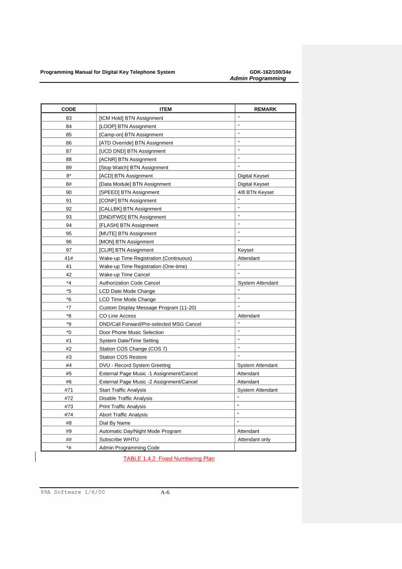
CODE ITEM REMARK
83 [ICM Hold] BTN Assignment "
84 [LOOP] BTN Assignment "
85 [Camp-on] BTN Assignment "
86 [ATD Override] BTN Assignment "
87 [UCD DND] BTN Assignment "
88 [ACNR] BTN Assignment "
89 [Stop Watch] BTN Assignment "
8* [ACD] BTN Assignment Digital Keyset
8# [Data Module] BTN Assignment Digital Keyset
90 [SPEED] BTN Assignment 4/8 BTN Keyset
91 [CONF] BTN Assignment "
92 [CALLBK] BTN Assignment "
93 [DND/FWD] BTN Assignment "
94 [FLASH] BTN Assignment "
95 [MUTE] BTN Assignment "
96 [MON] BTN Assignment "
97 [CLIR] BTN Assignment Keyset
41# Wake-up Time Registration (Continuous) Attendant
41 Wake-up Time Registration (One-time) "
42 Wake-up Time Cancel "
*4 Authorization Code Cancel System Attendant
*5 LCD Date Mode Change "
*6 LCD Time Mode Change "
*7 Custom Display Message Program (11-20) "
*8 CO Line Access Attendant
*9 DND/Call Forward/Pre-selected MSG Cancel "
*0 Door Phone Music Selection "
#1 System Date/Time Setting "
#2 Station COS Change (COS 7) "
#3 Station COS Restore "
#4 DVU - Record System Greeting System Attendant
#5 External Page Music -1 Assignment/Cancel Attendant
#6 External Page Music -2 Assignment/Cancel Attendant
#71 Start Traffic Analysis System Attendant
#72 Disable Traffic Analysis "
#73 Print Traffic Analysis "
#74 Abort Traffic Analysis "
#8 Dial By Name "
#9 Automatic Day/Night Mode Program Attendant
## Subscribe WHTU Attendant only
*# Admin Programming Code
TABLE 1.4.2 Fixed Numbering Plan
Programming Manual for Digital Key Telephone System GDK-162/100/34e
Admin Programming
99A Software 1/6/00 A-7
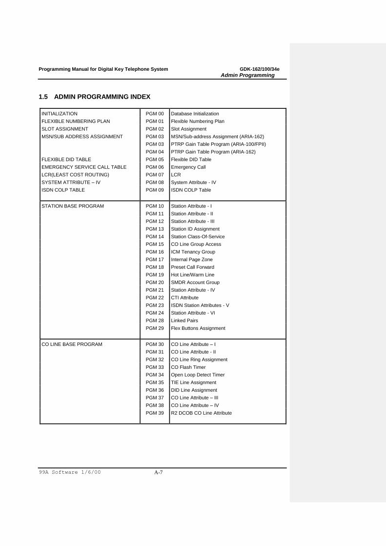
1.5 ADMIN PROGRAMMING INDEX
INITIALIZATION PGM 00 Database Initialization
FLEXIBLE NUMBERING PLAN PGM 01 Flexible Numbering Plan
SLOT ASSIGNMENT PGM 02 Slot Assignment
MSN/SUB ADDRESS ASSIGNMENT PGM 03
PGM 03
PGM 04
MSN/Sub-address Assignment (ARIA-162)
PTRP Gain Table Program (ARIA-100/FPII)
PTRP Gain Table Program (ARIA-162)
FLEXIBLE DID TABLE PGM 05 Flexible DID Table
EMERGENCY SERVICE CALL TABLE PGM 06 Emergency Call
LCR(LEAST COST ROUTING) PGM 07 LCR
SYSTEM ATTRIBUTE – IV PGM 08 System Attribute - IV
ISDN COLP TABLE PGM 09 ISDN COLP Table
STATION BASE PROGRAM PGM 10 Station Attribute - I
PGM 11 Station Attribute - II
PGM 12 Station Attribute - III
PGM 13 Station ID Assignment
PGM 14 Station Class-Of-Service
PGM 15 CO Line Group Access
PGM 16 ICM Tenancy Group
PGM 17 Internal Page Zone
PGM 18 Preset Call Forward
PGM 19 Hot Line/Warm Line
PGM 20 SMDR Account Group
PGM 21 Station Attribute - IV
PGM 22 CTI Attribute
PGM 23 ISDN Station Attributes - V
PGM 24 Station Attribute - VI
PGM 28 Linked Pairs
PGM 29 Flex Buttons Assignment
CO LINE BASE PROGRAM PGM 30 CO Line Attribute – I
PGM 31 CO Line Attribute - II
PGM 32 CO Line Ring Assignment
PGM 33 CO Flash Timer
PGM 34 Open Loop Detect Timer
PGM 35 TIE Line Assignment
PGM 36 DID Line Assignment
PGM 37 CO Line Attribute – III
PGM 38 CO Line Attribute – IV
PGM 39 R2 DCOB CO Line Attribute
Programming Manual for Digital Key Telephone System GDK-162/100/34e
Admin Programming
99A Software 1/6/00 A-8
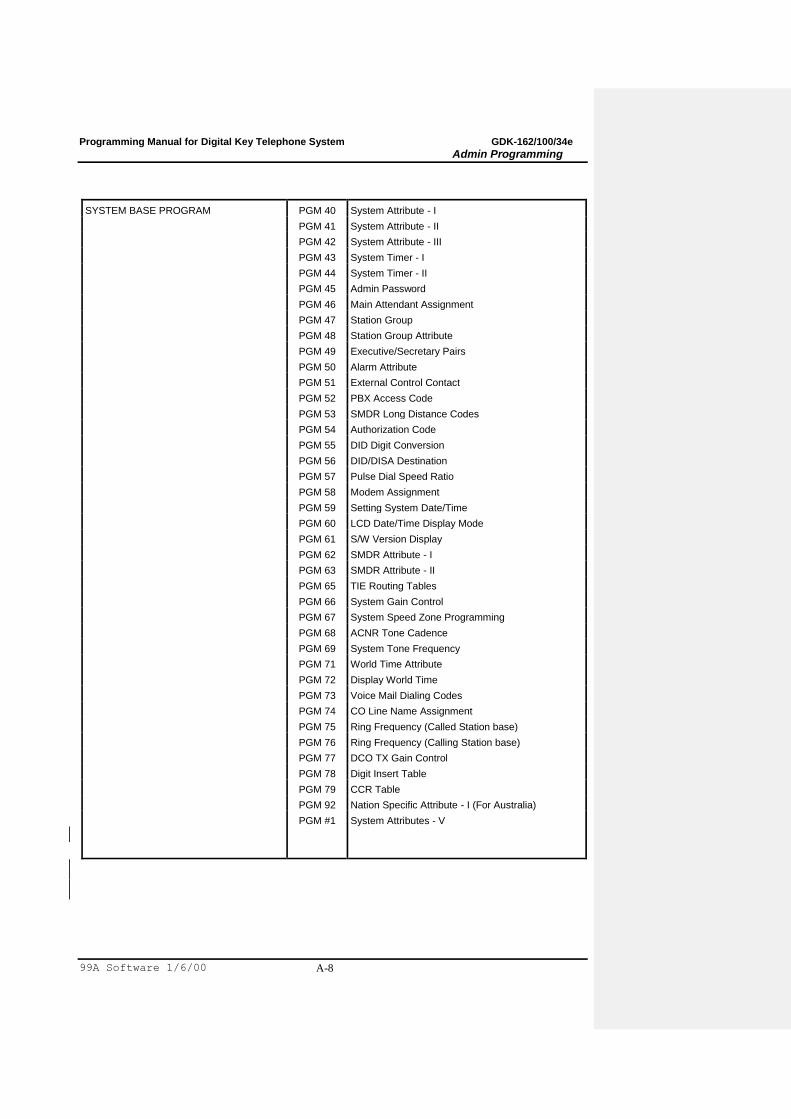
SYSTEM BASE PROGRAM PGM 40 System Attribute - I
PGM 41 System Attribute - II
PGM 42 System Attribute - III
PGM 43 System Timer - I
PGM 44 System Timer - II
PGM 45 Admin Password
PGM 46 Main Attendant Assignment
PGM 47 Station Group
PGM 48 Station Group Attribute
PGM 49 Executive/Secretary Pairs
PGM 50 Alarm Attribute
PGM 51 External Control Contact
PGM 52 PBX Access Code
PGM 53 SMDR Long Distance Codes
PGM 54 Authorization Code
PGM 55 DID Digit Conversion
PGM 56 DID/DISA Destination
PGM 57 Pulse Dial Speed Ratio
PGM 58 Modem Assignment
PGM 59 Setting System Date/Time
PGM 60 LCD Date/Time Display Mode
PGM 61 S/W Version Display
PGM 62 SMDR Attribute - I
PGM 63 SMDR Attribute - II
PGM 65 TIE Routing Tables
PGM 66 System Gain Control
PGM 67 System Speed Zone Programming
PGM 68 ACNR Tone Cadence
PGM 69 System Tone Frequency
PGM 71 World Time Attribute
PGM 72 Display World Time
PGM 73 Voice Mail Dialing Codes
PGM 74 CO Line Name Assignment
PGM 75 Ring Frequency (Called Station base)
PGM 76 Ring Frequency (Calling Station base)
PGM 77 DCO TX Gain Control
PGM 78 Digit Insert Table
PGM 79 CCR Table
PGM 92 Nation Specific Attribute - I (For Australia)
PGM #1 System Attributes - V

Programming Manual for Digital Key Telephone System GDK-162/100/34e
Admin Programming
99A Software 1/6/00 A-9
TOLL TABLE PGM 70 Exception Table
PGM 64 Canned Toll Exception Table
PRINT DATABASE PGM 80 Database Print
QSIG TABLE PGM *1 QSIG Basic Attribute
PGM *2 QSIG Routing Table
TABLE 1.5.1 Admin Programming Index
Programming Manual for Digital Key Telephone System GDK-162/100/34e
Admin Programming
99A Software 1/6/00 A-10
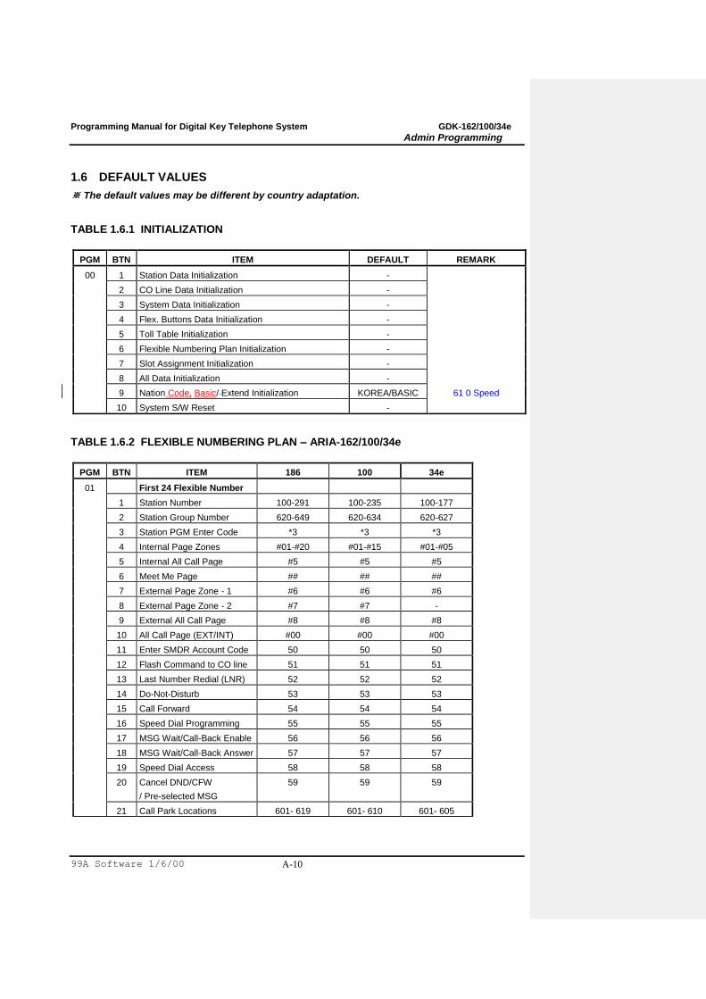
1.6 DEFAULT VALUES
※ The default values may be different by country adaptation.
TABLE 1.6.1 INITIALIZATION
PGM BTN ITEM DEFAULT REMARK
00 1 Station Data Initialization -
2 CO Line Data Initialization -
3 System Data Initialization -
4 Flex. Buttons Data Initialization -
5 Toll Table Initialization -
6 Flexible Numbering Plan Initialization -
7 Slot Assignment Initialization -
8 All Data Initialization -
9 Nation Code, Basic/ Extend Initialization KOREA/BASIC 61 0 Speed
10 System S/W Reset -
TABLE 1.6.2 FLEXIBLE NUMBERING PLAN – ARIA-162/100/34e
PGM BTN ITEM 186 100 34e
01 First 24 Flexible Number
1 Station Number 100-291 100-235 100-177
2 Station Group Number 620-649 620-634 620-627
3 Station PGM Enter Code *3 *3 *3
4 Internal Page Zones #01-#20 #01-#15 #01-#05
5 Internal All Call Page #5 #5 #5
6 Meet Me Page ## ## ##
7 External Page Zone - 1 #6 #6 #6
8 External Page Zone - 2 #7 #7 -
9 External All Call Page #8 #8 #8
10 All Call Page (EXT/INT) #00 #00 #00
11 Enter SMDR Account Code 50 50 50
12 Flash Command to CO line 51 51 51
13 Last Number Redial (LNR) 52 52 52
14 Do-Not-Disturb 53 53 53
15 Call Forward 54 54 54
16 Speed Dial Programming 55 55 55
17 MSG Wait/Call-Back Enable 56 56 56
18 MSG Wait/Call-Back Answer 57 57 57
19 Speed Dial Access 58 58 58
20 Cancel DND/CFW
/ Pre-selected MSG
59 59 59
21 Call Park Locations 601- 619 601- 610 601- 605
Programming Manual for Digital Key Telephone System GDK-162/100/34e
Admin Programming
99A Software 1/6/00 A-11
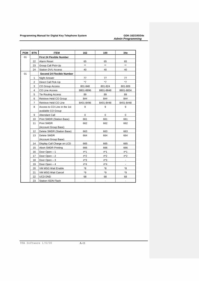
PGM BTN ITEM 162 100 34e
01 First 24 Flexible Number
22 Alarm Reset 65 65 65
23 Group Call Pick-Up ** ** **
24 Station DVU Access 40 40 40
01 Second 24 Flexible Number
1 Night Answer 77 77 77
2 Direct Call Pick-Up *7 *7 *7
3 CO Group Access 801-848 801-824 801-809
4 CO Line Access 8801-8896 8801-8848 8801-8834
5 Tie Routing Access 89 89 89
6 Retrieve Held CO Group 8## 8## 8##
7 Retrieve Held CO Line 8#01-8#96 8#01-8#48 8#01-8#48
8 Access to CO Line in the 1st
available CO Group
9 9 9
9 Attendant Call 0 0 0
10 Print SMDR (Station Base) 661 661 661
11 Print SMDR
(Account Group Base)
662 662 662
12 Delete SMDR (Station Base) 663 663 663
13 Delete SMDR
(Account Group Base)
664 664 664
14 Display Call Charge on LCD 665 665 665
15 Abort SMDR Printing 666 666 666
16 Door Open – 1 #*1 #*1 #*1
17 Door Open – 2 #*2 #*2 #*2
18 Door Open – 3 #*3 #*3 -
19 Door Open – 4 #*4 #*4 -
20 VM MSG Wait Enable *8 *8 *8
21 VM MSG Wait Cancel *9 *9 *9
22 UCD DND 68 68 68
23 Station ISDN Flash - - -

Programming Manual for Digital Key Telephone System GDK-162/100/34e
Admin Programming
99A Software 1/6/00 A-12
TABLE 1.6.3 SLOT ASSIGNMENT
PGM SYS BTN DEFAULT REMARK
02 ARIA-FP II 1 03 CO Line Slot Assignment
Max. 34 CO lines or Max. 6 slots
2 02 Station Slot Assignment
Max. 78 stations or Max. 7 slots
3 08 WTIB Port Number
4 30 No. of Basic Primary Dev. (PRIB, DCOB, R2)
ARIA-100 1 08 07 06 12 11 CO Line Slot Assignment
Max. 48 CO lines or Max. 8 slots
2 01 02 03 04 05 09 10 11 Station Slot Assignment
Max. 136 stations
3 08 WTIB Port Number
4 30 No. of Basic Primary Dev. (PRIB, DCOB, R2)
ARIA-162 1 06 07 08 14 15 16 17 CO Line Slot Assignment
Max. 96 CO lines
2 02 03 04 05 09 10 11 12 13 Station Slot Assignment
Max. 186 stations
3 08 WTIB Port Number
4 30 No. of Basic Primary Dev. (PRIB, DCOB, R2)
5 30 No. of Option Primary Dev. (PRIU)
TABLE 1.6.4 MSN/SUB-ADDRESS ASSIGNMENT
PGM BTN ITEM RANGE DEFAULT REMARK
03 1 CO Line Number 01-96/48/34 PGM 03: 162
(04) 2 Flex DID Table(PGM 05) Index PGM 04:
100/FPII
3 MSN/Sub-address Number 0-9
4 Telephone Number 20 digits

Programming Manual for Digital Key Telephone System GDK-162/100/34e
Admin Programming
99A Software 1/6/00 A-13
TABLE 1.6.5 FLEXIBLE DID TABLE PROGRAM
PGM BTN SUB-
BTN
ITEM RANGE DEFAULT REMARK
05 1 1 Bin Number 000-999299
2 CO Name (DID Name) 11 digits
3 Day Destination Bin Number STA/STA Grp/DVU
4 Night Destination Bin Number STA/STA Grp/DVU
2 Restore default
3 Clear table
TABLE 1.6.6 EMERGENCY SERVICE CALL
PGM BTN ITEM RANGE DEFAULT REMARK
06 1~10 Emergency Service Call Table 5 digits
TABLE 1.6.7 LCR TABLE ASSIGNMENT
PGM BTN ITEM RANGE DEFAULT REMARK
07 1 LCR Access Mode M00/M01/M02/M11/M12/M13 M00
2 Set the Day of week zone 1~7 1234567
3 Set the Time of week zone 00~24 0024
4 LCR Leading Digit Table
5 Digit Modification Table
6 Initialization of LCR Database
TABLE 1.6.8 SYSTEM ATTRIBUTE - IV
PGM BTN ITEM RANGE DEFAULT REMARK
08 1 Prefix Code Insertion 1/0 0 (OFF) On
2 My area code 5 digits 2
3 CO ATD Code 2 digits
4 DID Conversion Table 0/1/2 0
5 Calling Sub Address 1/0 0 (OFF)
6 Type of Calling Number 0~4 2 (National No.)
7 Advice of Charge 0~5 0
8 Out Zero Insertion 1/0 1 (ON)
9 Paging Conference Index Internal Page Group
10 U-A Law Line Installed 1/0 0 (OFF)
11 ISDN Sending Mode 1/0 0 (Overlap) For Israel
Programming Manual for Digital Key Telephone System GDK-162/100/34e
Admin Programming
99A Software 1/6/00 A-14
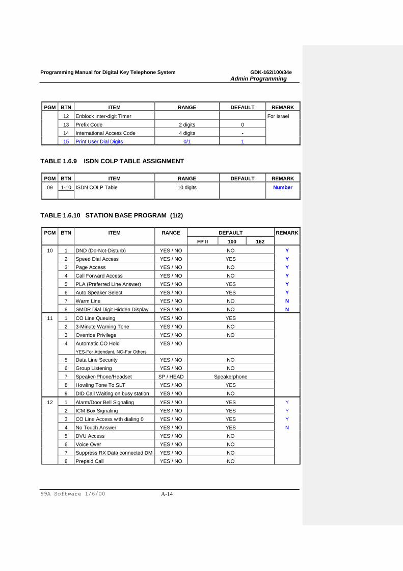
PGM BTN ITEM RANGE DEFAULT REMARK
12 Enblock Inter-digit Timer For Israel
13 Prefix Code 2 digits 0
14 International Access Code 4 digits -
15 Print User Dial Digits 0/1 1
TABLE 1.6.9 ISDN COLP TABLE ASSIGNMENT
PGM BTN ITEM RANGE DEFAULT REMARK
09 1-10 ISDN COLP Table 10 digits Number
TABLE 1.6.10 STATION BASE PROGRAM (1/2)
PGM BTN ITEM RANGE DEFAULT REMARK
FP II 100 162
10 1 DND (Do-Not-Disturb) YES / NO NO Y
2 Speed Dial Access YES / NO YES Y
3 Page Access YES / NO NO Y
4 Call Forward Access YES / NO NO Y
5 PLA (Preferred Line Answer) YES / NO YES Y
6 Auto Speaker Select YES / NO YES Y
7 Warm Line YES / NO NO N
8 SMDR Dial Digit Hidden Display YES / NO NO N
11 1 CO Line Queuing YES / NO YES
2 3-Minute Warning Tone YES / NO NO
3 Override Privilege YES / NO NO
4 Automatic CO Hold
YES-For Attendant, NO-For Others
YES / NO
5 Data Line Security YES / NO NO
6 Group Listening YES / NO NO
7 Speaker-Phone/Headset SP / HEAD Speakerphone
8 Howling Tone To SLT YES / NO YES
9 DID Call Waiting on busy station YES / NO NO
12 1 Alarm/Door Bell Signaling YES / NO YES Y
2 ICM Box Signaling YES / NO YES Y
3 CO Line Access with dialing 0 YES / NO YES Y
4 No Touch Answer YES / NO YES N
5 DVU Access YES / NO NO
6 Voice Over YES / NO NO
7 Suppress RX Data connected DM YES / NO NO
8 Prepaid Call YES / NO NO
Programming Manual for Digital Key Telephone System GDK-162/100/34e
Admin Programming
99A Software 1/6/00 A-15
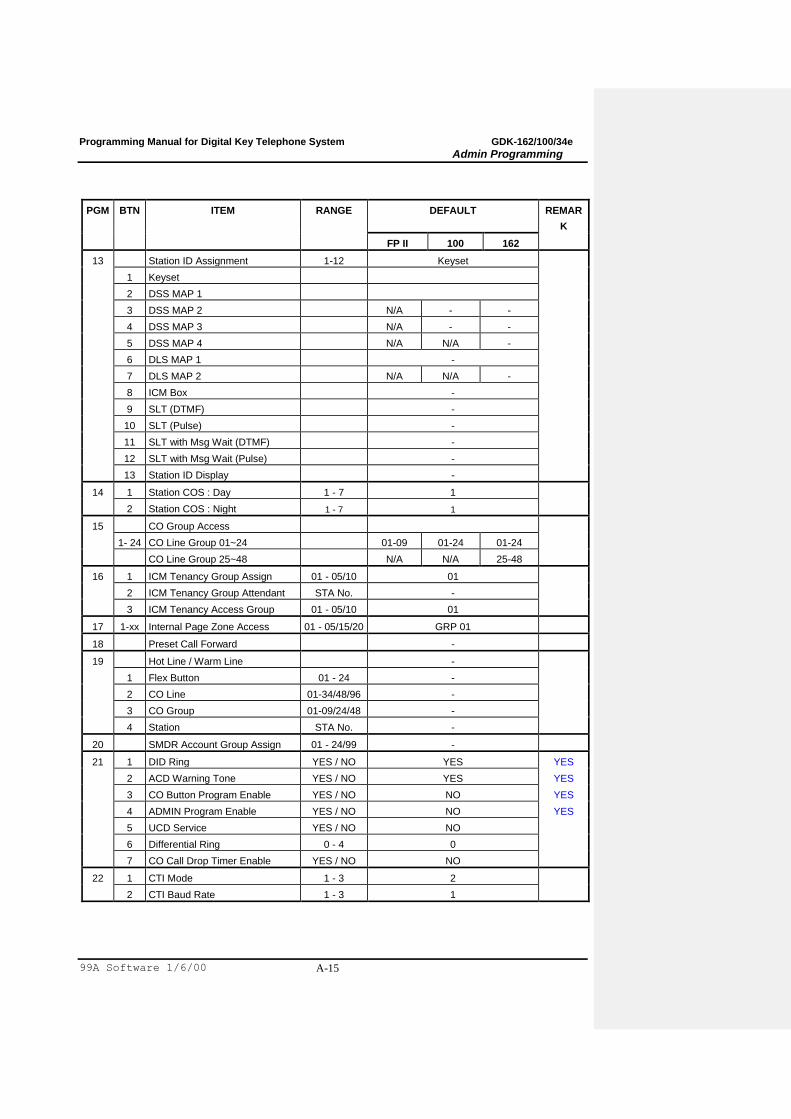
PGM BTN ITEM RANGE DEFAULT REMAR
K
FP II 100 162
13 Station ID Assignment 1-12 Keyset
1 Keyset
2 DSS MAP 1
3 DSS MAP 2 N/A - -
4 DSS MAP 3 N/A - -
5 DSS MAP 4 N/A N/A -
6 DLS MAP 1 -
7 DLS MAP 2 N/A N/A -
8 ICM Box -
9 SLT (DTMF) -
10 SLT (Pulse) -
11 SLT with Msg Wait (DTMF) -
12 SLT with Msg Wait (Pulse) -
13 Station ID Display -
14 1 Station COS : Day 1 - 7 1
2 Station COS : Night 1 - 7 1
15 CO Group Access
1- 24 CO Line Group 01~24 01-09 01-24 01-24
CO Line Group 25~48 N/A N/A 25-48
16 1 ICM Tenancy Group Assign 01 - 05/10 01
2 ICM Tenancy Group Attendant STA No. -
3 ICM Tenancy Access Group 01 - 05/10 01
17 1-xx Internal Page Zone Access 01 - 05/15/20 GRP 01
18 Preset Call Forward -
19 Hot Line / Warm Line -
1 Flex Button 01 - 24 -
2 CO Line 01-34/48/96 -
3 CO Group 01-09/24/48 -
4 Station STA No. -
20 SMDR Account Group Assign 01 - 24/99 -
21 1 DID Ring YES / NO YES YES
2 ACD Warning Tone YES / NO YES YES
3 CO Button Program Enable YES / NO NO YES
4 ADMIN Program Enable YES / NO NO YES
5 UCD Service YES / NO NO
6 Differential Ring 0 - 4 0
7 CO Call Drop Timer Enable YES / NO NO
22 1 CTI Mode 1 - 3 2
2 CTI Baud Rate 1 - 3 1
Programming Manual for Digital Key Telephone System GDK-162/100/34e
Admin Programming
99A Software 1/6/00 A-16
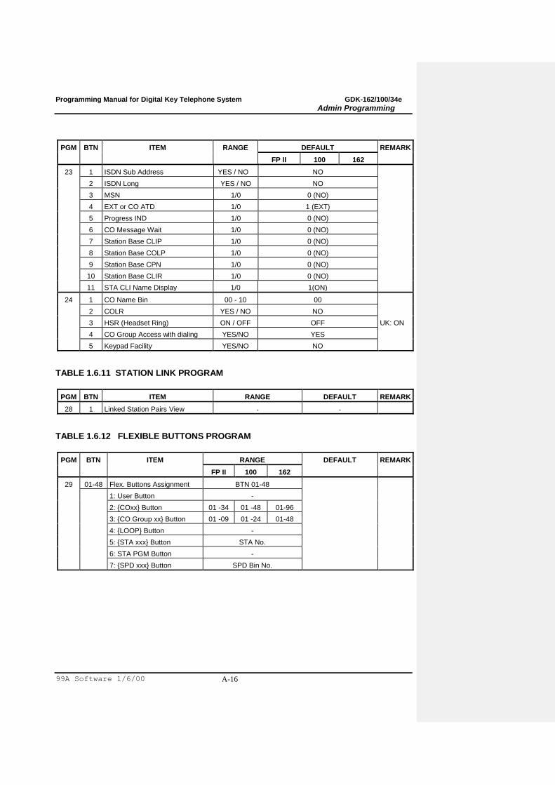
PGM BTN ITEM RANGE DEFAULT REMARK
FP II 100 162
23 1 ISDN Sub Address YES / NO NO
2 ISDN Long YES / NO NO
3 MSN 1/0 0 (NO)
4 EXT or CO ATD 1/0 1 (EXT)
5 Progress IND 1/0 0 (NO)
6 CO Message Wait 1/0 0 (NO)
7 Station Base CLIP 1/0 0 (NO)
8 Station Base COLP 1/0 0 (NO)
9 Station Base CPN 1/0 0 (NO)
10 Station Base CLIR 1/0 0 (NO)
11 STA CLI Name Display 1/0 1(ON)
24 1 CO Name Bin 00 - 10 00
2 COLR YES / NO NO
3 HSR (Headset Ring) ON / OFF OFF UK: ON
4 CO Group Access with dialing YES/NO YES
5 Keypad Facility YES/NO NO
TABLE 1.6.11 STATION LINK PROGRAM
PGM BTN ITEM RANGE DEFAULT REMARK
28 1 Linked Station Pairs View - -
TABLE 1.6.12 FLEXIBLE BUTTONS PROGRAM
PGM BTN ITEM RANGE DEFAULT REMARK
FP II 100 162
29 01-48 Flex. Buttons Assignment BTN 01-48
1: User Button -
2: {COxx} Button 01 -34 01 -48 01-96
3: {CO Group xx} Button 01 -09 01 -24 01-48
4: {LOOP} Button -
5: {STA xxx} Button STA No.
6: STA PGM Button -
7: {SPD xxx} Button SPD Bin No.
Programming Manual for Digital Key Telephone System GDK-162/100/34e
Admin Programming
99A Software 1/6/00 A-17
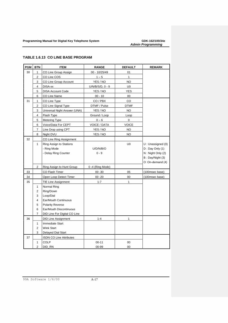
TABLE 1.6.13 CO LINE BASE PROGRAM
PGM BTN ITEM RANGE DEFAULT REMARK
30 1 CO Line Group Assign 00 - 10/25/49 01
2 CO Line COS 1 – 5 1
3 CO Line Group Account YES / NO NO
4 DISA-xx U/N/B/S/D, 0 - 9 U0
5 DISA Account Code YES / NO YES
6 CO Line Name 00 - 10 00
31 1 CO Line Type CO / PBX CO
2 CO Line Signal Type DTMF / Pulse DTMF
3 Universal Night Answer (UNA) YES / NO NO
4 Flash Type Ground / Loop Loop
5 Metering Type 0 – 6 0
6 Voice/Data For CEPT VOICE / DATA VOICE
7 Line Drop using CPT YES / NO NO
8 Night DVU YES / NO NO
32 CO Line Ring Assignment
1 Ring Assign to Stations
- Ring Mode
- Delay Ring Counter
U/D/N/B/O
0 - 9
U0 U : Unassigned (0)
D : Day Only (1)
N : Night Only (2)
B : Day/Night (3)
O :On-demand (4)
2 Ring Assign to Hunt Group 0 -4 (Ring Mode)
33 CO Flash Timer 00 -30 05 (100msec base)
34 Open Loop Detect Timer 00 -20 00 (100msec base)
35 TIE Line Assignment 1-7 1
1
2
3
4
5
6
7
Normal Ring
Ring/Down
Loop/Dial
Ear/Mouth Continuous
Polarity Reverse
Ear/Mouth Discontinuous
DID Line For Digital CO Line
36 DID Line Assignment 1-4 1
1
2
3
Immediate Start
Wink Start
Delayed Dial Start
37 ISDN CO Line Attributes
1
2
COLP
DID_RN
00-11
00-99
00
00
Programming Manual for Digital Key Telephone System GDK-162/100/34e
Admin Programming
99A Software 1/6/00 A-18
PGM BTN ITEM RANGE DEFAULT REMARK
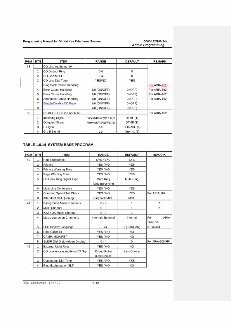
38 CO Line Attributes -IV
1
2
3
4
5
6
7
8
CO Distinct Ring
CO Line MOH
CO Line Dial Tone
Ring Back Cause Handling
Error Cause Handling
Busy Cause Handling
Announce Cause Handling
Enable/Disable CO Page
0-4
0-4
YES/NO
1/0 (ON/OFF)
1/0 (ON/OFF)
1/0 (ON/OFF)
1/0 (ON/OFF)
1/0 (ON/OFF)
0
0
YES
0 (OFF)
0 (OFF)
0 (OFF)
0 (OFF)
0 (OFF)
For ARIA-162
For ARIA-162
For ARIA-162
For ARIA-162
39 R2 DCOB CO Line Attribute For ARIA-162
1
2
3
4
Incoming Signal
Outgoing Signal
B-Signal
Grp II Signal
Pulse(0)/DTMF(1)/REC(2)
Pulse(0)/DTMF(1)/REC(2)
1-9
1-9
DTMF (1)
DTMF (1)
CHARGE (6)
Grp II-1 (1)
TABLE 1.6.14 SYSTEM BASE PROGRAM
PGM BTN ITEM RANGE DEFAULT REMARK
40 1 Hold Preference SYS / EXC SYS
2 Privacy YES / NO YES
3 Privacy Warning Tone YES / NO YES
4 Page Warning Tone YES / NO YES
5 Off-Hook Ring Signal Type Mute Ring
/One Burst Ring
Mute Ring
6 Multi-Line Conference YES / NO YES
7 Common Speed Toll Check YES / NO YES For ARIA-162
8 Attendant Call Queuing Ringback/MOH MOH
41 1 Background Music Channels 0 - 9 1 2
2 MOH Channel 0 - 9 1 2
3 ICM BOX Music Channel 0 - 9 1
4 Music source on Channel 1 Internal / External Internal For ARIA-
162/100
5 LCD Display Language 0 - 24 1 (KOREAN) 3 : Invalid
6 Print Caller-ID YES / NO NO
7 CAMP, MOH/RBT YES / NO NO
8 SMDR Dial Digit Hidden Display 0 - 4 0 For ARIA-100/FPII
42 1 External Night Ring YES / NO NO
2 CO Line Access mode in CO Grp Round Robin
/Last Choice
Last Choice
3 Continuous Dial-Tone YES / NO YES
4 Ring Exchange on SLT YES / NO NO

Programming Manual for Digital Key Telephone System GDK-162/100/34e
Admin Programming
99A Software 1/6/00 A-19
5 Dial-Tone Detect YES / NO NO

Programming Manual for Digital Key Telephone System GDK-162/100/34e
Admin Programming
99A Software 1/6/00 A-20
PGM BTN ITEM RANGE DEFAULT REMARK
6 Clear ACD Database after printing YES / NO NO
7 ACD Print Duration 10SEC / 1Hour 1 Hour
43 1 Exclusive Hold Recall Timer 000 - 300 060 1 sec base
2 System Hold Recall Timer 000 - 300 030 1 sec base 060
3 Transfer Recall Timer 000 - 300 030 1 sec base
4 I-Hold Recall Timer 000 - 300 030 1 sec base
5 ATD Recall Timer 00 - 60 01 1 min base
6 CO Ring Detect Timer 1 - 9 2 100 msec base
7 Pause Timer 3 1 - 9 3 1 sec base
8 CO Release Guard Timer 010 - 150 020 100 msec base
9 CO Warning Tone Timer 060 - 900 180 1 sec base
10 CO Dial Delay Timer 00 - 99 01 1 sec base
11 Call Park Timer 000 - 600 120 1 sec base
12 Preset Call Forward Timer 00 - 99 10 1 sec base
13 Unsupervised Conference Timer 00 - 99 10 1 min base
14 ACNR Retrial Pause Timer 030 - 300 030 1 sec base
15 ACNR Retrial Delay Timer 000 - 300 030 1 sec base
16 Flexible DID Time-out Timer 000 - 300 030 100 msec base
17 ACNR No Answer Timer 10 - 50 30 1 sec base
18 ACNR Retry Counter 1 - 3 3
19 Warm Line Timer 01 - 20 05 1 sec base
20 PBX Code Print 1 / 0 0
21 Prepaid Call Warning Tone Timer 00 - 99 15 1 sec base
22 DISA Retry Counter 1 - 13 3
23 COS when DISA seize CO 1 - 6 6 (UK: 1)
24 DVU Forward Answer Timer 04 - 40 04
25
25
R2 Out Manage Timer
ACNR Retry Time Count
01 - 50
1 - 9
14
3
For ARIA-162
For ARIA-100/FPII
26
26
R2 Pulse Timer
Switch Pause Timer
01 - 30
00 -40
7
00
For ARIA-162
For ARIA-100/FPII
27
27
DT Delay Timer
First CO Group OVR
01 - 30
0 / 1
20
1
For ARIA-162
For ARIA-100/FPII
28
28
ACNR Retry Time Count
CO Call Drop Timer
1 - 9
01 - 99
3
10
For ARIA-162
For ARIA-100/FPII
29 Switch Pause Timer 00 - 40 00 For ARIA-162
30 First CO group OVR 0 / 1 1 (UK : 0) For ARIA-162
31 R2 Incoming Manage Timer 01 - 50 14 N/A in FPII/100
32 R2 Disappear Timer 01 - 50 14 N/A in FPII/100
33 CO Call Drop Timer 01 - 99 10 1 min base
Programming Manual for Digital Key Telephone System GDK-162/100/34e
Admin Programming
99A Software 1/6/00 A-21
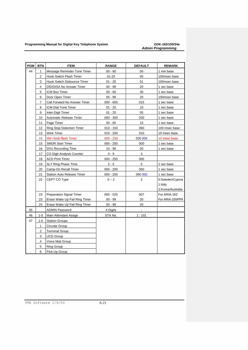
PGM BTN ITEM RANGE DEFAULT REMARK
44 1 Message Reminder Tone Timer 00 - 60 00 1 min base
2 Hook Switch Flash Timer 01-25 05 100msec base
3 Hook Switch Debounce Timer 01 - 25 01 100msec base
4 DID/DISA No Answer Timer 00 - 99 20 1 sec base
5 ICM Box Timer 00 - 60 30 1 sec base
6 Door Open Timer 05 - 99 20 100msec base
7 Call Forward No Answer Timer 000 - 600 015 1 sec base
8 ICM Dial-Tone Timer 01 - 20 10 1 sec base
9 Inter-Digit Timer 01 - 20 05 1 sec base
10 Automatic Release Timer 000 - 300 030 1 sec base
11 Page Timer 00 - 60 15 1 sec base
12 Ring Stop Detection Timer 010 - 150 060 100 msec base
13 Wink Timer 010 - 200 010 10 msec base
14 Min Hook-flash Timer 000 - 250 020 005 10 msec base
15 SMDR Start Timer 000 - 250 000 1 sec base
16 DVU Recording Time 10 - 90 20 1 sec base
17 CO Digit Analysis Counter 0 - 9 3
18 ACD Print Timer 000 - 255 000
19 SLT Ring Phase Time 2 - 5 5 1 sec base
20 Camp-On Recall Timer 000 - 200 050 1 sec base
21 Station Auto Release Timer 000 - 200 060 000 1 sec base
22 CEPT CO Type 0 – 2 2 0:Sweden/Cyprus
1:Italy
2:Korea/Australia
23
23
Preparation Signal Timer
Erase Wake Up Fail Ring Timer
000 - 025
00 - 99
007
20
For ARIA-162
For ARIA-100/FPII
24 Erase Wake Up Fail Ring Timer 00 - 99 20
45 ADMIN Password 4 Digits -
46 1-5 Main Attendant Assign STA No. 1 : 101
47 1-6 Station Groups
1 Circular Group
2 Terminal Group
3 UCD Group
4 Voice Mail Group
5 Ring Group
6 Pick-Up Group
Programming Manual for Digital Key Telephone System GDK-162/100/34e
Admin Programming
99A Software 1/6/00 A-22
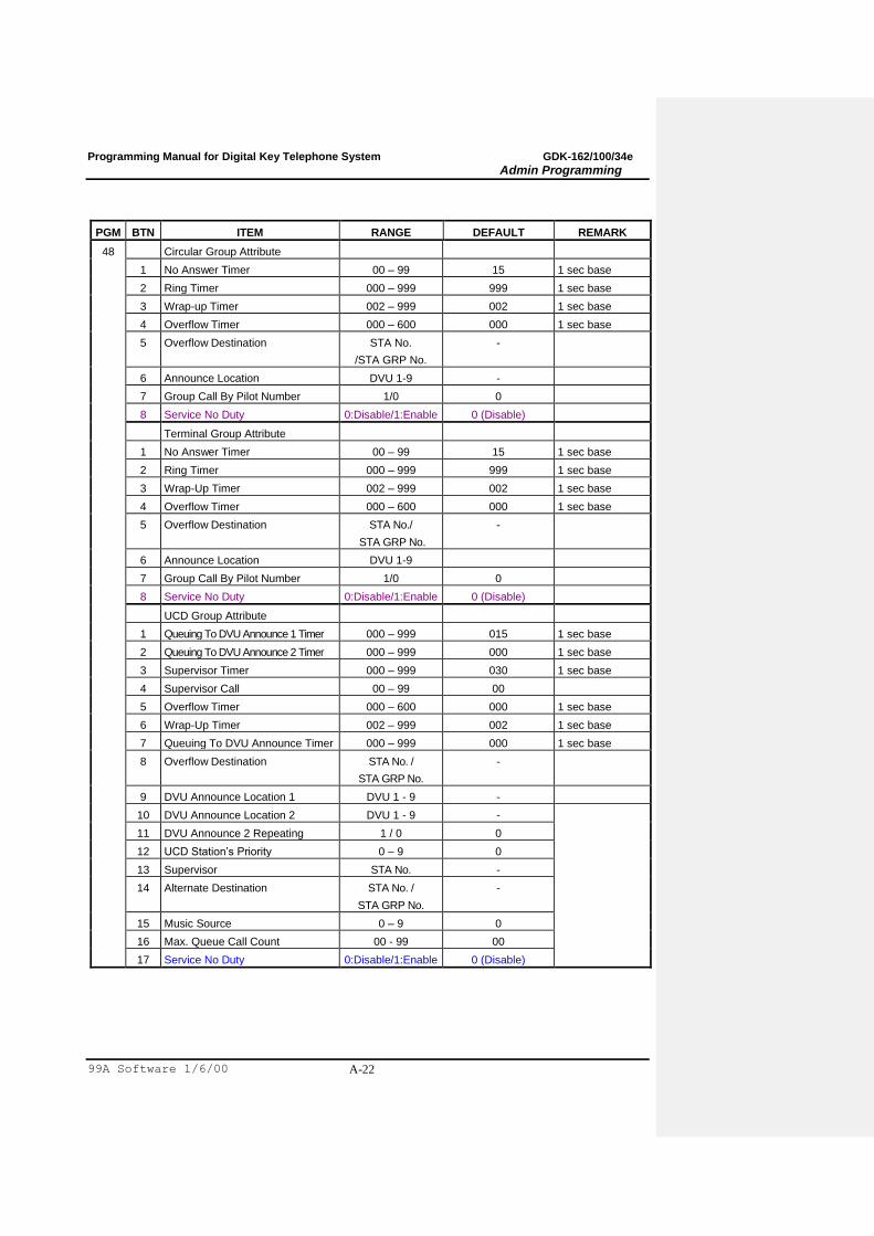
PGM BTN ITEM RANGE DEFAULT REMARK
48 Circular Group Attribute
1 No Answer Timer 00 – 99 15 1 sec base
2 Ring Timer 000 – 999 999 1 sec base
3 Wrap-up Timer 002 – 999 002 1 sec base
4 Overflow Timer 000 – 600 000 1 sec base
5 Overflow Destination STA No.
/STA GRP No.
-
6 Announce Location DVU 1-9 -
7 Group Call By Pilot Number 1/0 0
8 Service No Duty 0:Disable/1:Enable 0 (Disable)
Terminal Group Attribute
1 No Answer Timer 00 – 99 15 1 sec base
2 Ring Timer 000 – 999 999 1 sec base
3 Wrap-Up Timer 002 – 999 002 1 sec base
4 Overflow Timer 000 – 600 000 1 sec base
5 Overflow Destination STA No./
STA GRP No.
-
6 Announce Location DVU 1-9
7 Group Call By Pilot Number 1/0 0
8 Service No Duty 0:Disable/1:Enable 0 (Disable)
UCD Group Attribute
1 Queuing To DVU Announce 1 Timer 000 – 999 015 1 sec base
2 Queuing To DVU Announce 2 Timer 000 – 999 000 1 sec base
3 Supervisor Timer 000 – 999 030 1 sec base
4 Supervisor Call 00 – 99 00
5 Overflow Timer 000 – 600 000 1 sec base
6 Wrap-Up Timer 002 – 999 002 1 sec base
7 Queuing To DVU Announce Timer 000 – 999 000 1 sec base
8 Overflow Destination STA No. /
STA GRP No.
-
9 DVU Announce Location 1 DVU 1 - 9 -
10 DVU Announce Location 2 DVU 1 - 9 -
11 DVU Announce 2 Repeating 1 / 0 0
12 UCD Station‟s Priority 0 – 9 0
13 Supervisor STA No. -
14 Alternate Destination STA No. /
STA GRP No.
-
15 Music Source 0 – 9 0
16 Max. Queue Call Count 00 - 99 00
17 Service No Duty 0:Disable/1:Enable 0 (Disable)
Programming Manual for Digital Key Telephone System GDK-162/100/34e
Admin Programming
99A Software 1/6/00 A-23
PGM BTN ITEM RANGE DEFAULT REMARK
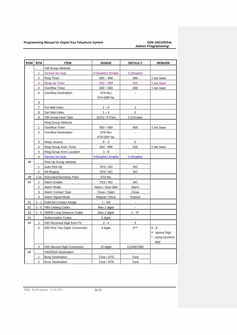
VM Group Attribute
1 Service No Duty 0:Disable/1:Enable 0 (Disable)
2 Ring Timer 000 – 999 999 1 sec base
3 Wrap-up Timer 002 – 999 002 1 sec base
4 Overflow Timer 000 – 600 000 1 sec base
5 Overflow Destination STA No./
STA GRP No.
-
6
7 Put Mail Index 1 – 4 1
8 Get Mail Index 1 – 4 2
9 VM Group Hunt Type 1(Cir) / 0 (Ter) 1 (Circular)
Ring Group Attribute
1 Overflow Timer 000 – 600 600 1 sec base
2 Overflow Destination STA No./
STA GRP No.
-
3 Music Source 0 – 2 0
4 Ring Group Annc Timer 000 - 999 015 1 sec base
5 Ring Group Annc Location 1 - 9 -
6 Service No Duty 0:Disable/1:Enable 0 (Disable)
48 Pick-Up Group Attribute
1 Auto Pick-Up YES / NO NO
2 All Ringing YES / NO NO
49 1-xx Executive/Secretary Pairs STA No. -
50 1 Alarm Enable YES / NO NO
2 Alarm Mode Alarm / Door-Bell Alarm
3 Alarm Contact Type Close / Open Close
4 Alarm Signal Mode Repeat / Once Repeat
51 1 - x External Contact Assign 1 - 4/6 -
52 1 - 5 PBX Dialing Codes Max 2 digits -
53 1 - 5 SMDR Long Distance Codes Max 2 digits 1 : "0"
54 Authorization Codes 5 digits -
55 1 DID Received Digit from PX 2 - 4 3
2 DID First Two Digits Conversion 4 digits #*** 0 - 9
# : Ignore Digit
* : using received
digit
3 DID Second Digit Conversion 10 digits 1234567890
56 DID/DISA Destination
1 Busy Destination Tone / ATD Tone
2 Error Destination Tone / ATD Tone
Programming Manual for Digital Key Telephone System GDK-162/100/34e
Admin Programming
99A Software 1/6/00 A-24
PGM BTN ITEM RANGE DEFAULT REMARK
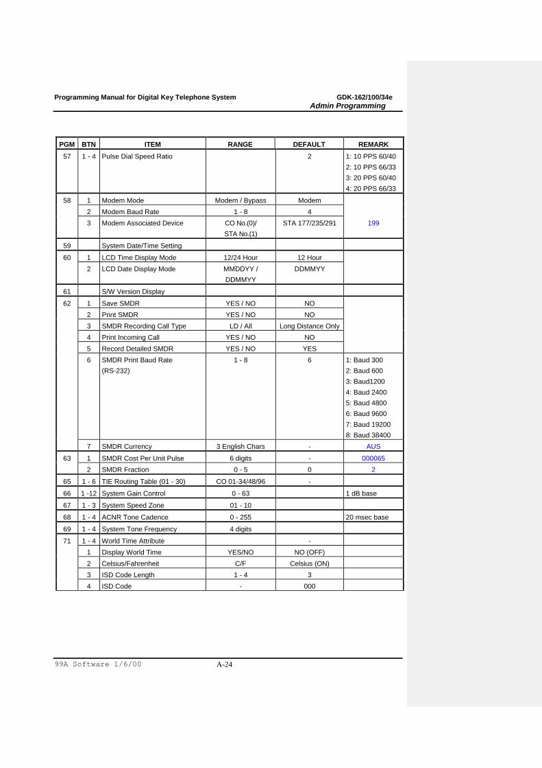
57 1 - 4 Pulse Dial Speed Ratio 2 1: 10 PPS 60/40
2: 10 PPS 66/33
3: 20 PPS 60/40
4: 20 PPS 66/33
58 1 Modem Mode Modem / Bypass Modem
2 Modem Baud Rate 1 - 8 4
3 Modem Associated Device CO No.(0)/
STA No.(1)
STA 177/235/291 199
59 System Date/Time Setting
60 1 LCD Time Display Mode 12/24 Hour 12 Hour
2 LCD Date Display Mode MMDDYY /
DDMMYY
DDMMYY
61 S/W Version Display
62 1 Save SMDR YES / NO NO
2 Print SMDR YES / NO NO
3 SMDR Recording Call Type LD / All Long Distance Only
4 Print Incoming Call YES / NO NO
5 Record Detailed SMDR YES / NO YES
6 SMDR Print Baud Rate
(RS-232)
1 - 8 6 1: Baud 300
2: Baud 600
3: Baud1200
4: Baud 2400
5: Baud 4800
6: Baud 9600
7: Baud 19200
8: Baud 38400
7 SMDR Currency 3 English Chars - AUS
63 1 SMDR Cost Per Unit Pulse 6 digits - 000065
2 SMDR Fraction 0 - 5 0 2
65 1 - 6 TIE Routing Table (01 - 30) CO 01-34/48/96 -
66 1 -12 System Gain Control 0 - 63 1 dB base
67 1 - 3 System Speed Zone 01 - 10
68 1 - 4 ACNR Tone Cadence 0 - 255 20 msec base
69 1 - 4 System Tone Frequency 4 digits
71 1 - 4 World Time Attribute -
1 Display World Time YES/NO NO (OFF)
2 Celsius/Fahrenheit C/F Celsius (ON)
3 ISD Code Length 1 - 4 3
4 ISD Code - 000

Programming Manual for Digital Key Telephone System GDK-162/100/34e
Admin Programming
99A Software 1/6/00 A-25
PGM BTN ITEM RANGE DEFAULT REMARK
72 1 - 4 World Time
1 Nation Code 3 digits -
2 Area Code 4 digits -
3 Equation of Time 00-23 00
4 Temperature 000
73 1 - 9 VM dialing Table Max. 12 digits
74 CO Line Name (01-10) Max. 12 ENG. chars -
75 1 - 4 Ring Frequency 0000 - 9999
76 1 - 4 Distinct Ring Frequency 0000 - 9999
77 1 - 7 DCO TX Gain 00 - 63 1 dB base
78 1 - 3 Digit Insert Table
TABLE 1.6.15 TOLL TABLE
PGM BTN ITEM RANGE DEFAULT REMARK
70 Exception Tables
1 Allowed Table A 01 - 20 -
2 Denied Table A 01 - 10 -
3 Allowed Table B 01 - 20 -
4 Denied Table B 01 - 10 -
64 Canned Toll Exception Table
1 Allowed Table 01 - 10
2 Denied Table 01 - 10
79 CCR Tables 01 - 09
TABLE 1.6.16 PRINT DATABASE
PGM BTN ITEM REMARK
80 1 Print Flexible Numbering Plan
2 Print Slot Assignment
3 Print Station Database
4 Print Flex Buttons Assignment
5 Print CO Line Database
6 Print System Database
7 Print Toll Tables
8 Print System Speed Dial Bins
9 Print All Database
10 Print Specific Nation‟s Database
11 Print QSIG Admin Database

Programming Manual for Digital Key Telephone System GDK-162/100/34e
Admin Programming
99A Software 1/6/00 A-26
TABLE 1.6.17 NATION SPECIFIC SYSTEM PROGRAM
PGM BTN ITEM RANGE DEFAULT REMARK
92 1 CPE CO Connection Program For Australia
2 CPE Port Selection Program
3 CLI TEL No. or Name Display
TABLE 1.6.18 SYSTEM ATTRIBUTE - V
PGM BTN BTN ITEM RANGE DEFAULT REMARK
#1 1 Virtual DIP Switch For ARIA-FPII only
1 CTS ON/OFF OFF
2 SOFT ON/OFF OFF
3 ECHO ON/OFF OFF
4 XONOFF ON/OFF OFF
2 1-5 Assign MOH via SLT Station No
6 1-8 Print Port Selection 1-2(4) 1
Programming Manual for Digital Key Telephone System GDK-162/100/34e
Admin Programming
99A Software 1/6/00 A-27
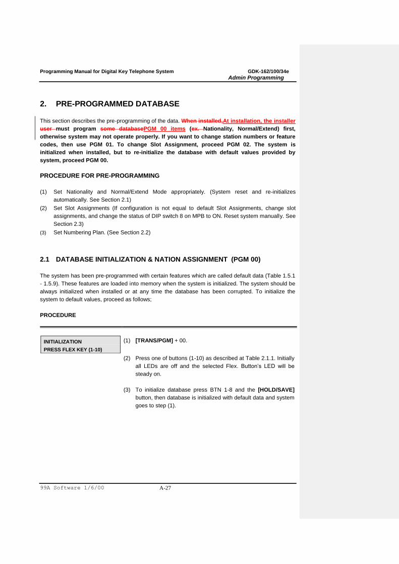
2. PRE-PROGRAMMED DATABASE
This section describes the pre-programming of the data. When installed,At installation, the installer
user must program some databasePGM 00 items (ex. Nationality, Normal/Extend) first,
otherwise system may not operate properly. If you want to change station numbers or feature
codes, then use PGM 01. To change Slot Assignment, proceed PGM 02. The system is
initialized when installed, but to re-initialize the database with default values provided by
system, proceed PGM 00.
PROCEDURE FOR PRE-PROGRAMMING
(1) Set Nationality and Normal/Extend Mode appropriately. (System reset and re-initializes
automatically. See Section 2.1)
(2) Set Slot Assignments (If configuration is not equal to default Slot Assignments, change slot
assignments, and change the status of DIP switch 8 on MPB to ON. Reset system manually. See
Section 2.3)
(3) Set Numbering Plan. (See Section 2.2)
2.1 DATABASE INITIALIZATION & NATION ASSIGNMENT (PGM 00)
The system has been pre-programmed with certain features which are called default data (Table 1.5.1
- 1.5.9). These features are loaded into memory when the system is initialized. The system should be
always initialized when installed or at any time the database has been corrupted. To initialize the
system to default values, proceed as follows;
PROCEDURE
INITIALIZATION
PRESS FLEX KEY (1-10)
(1) [TRANS/PGM] + 00.
(2) Press one of buttons (1-10) as described at Table 2.1.1. Initially
all LEDs are off and the selected Flex. Button‟s LED will be
steady on.
(3) To initialize database press BTN 1-8 and the [HOLD/SAVE]
button, then database is initialized with default data and system
goes to step (1).

Programming Manual for Digital Key Telephone System GDK-162/100/34e
Admin Programming
99A Software 1/6/00 A-28
INITIALIZATION
NATION: 61 EXTEND: NO
(4) In ARIA-162, to assign Nationality or and Normal/Extend
Numbering type,
i) Press BTN 9.
ii) Dial a nation code. ( 61 for Australia).
iii) Dial 0.
iv) Press the [SPEED] button. Then LCD shows the nation
code and numbering type.
v) Press the [HOLD/SAVE] button for permanent updating. In
this caseThe system is reset automatically. (Ex. Nation is
Korea, and Basic Numbering Type as default.)
(5) To reset the system, press BTN 10 and the [HOLD/SAVE]
button.
(7)(6)Press [] button instead of the [HOLD/SAVE] button, then
system goes to step (1) with no updating system memory.
Formatted: Bullets and Numbering

Programming Manual for Digital Key Telephone System GDK-162/100/34e
Admin Programming
99A Software 1/6/00 A-29
BTN ITEM
1 Station Database Initialization
2 CO Line Database Initialization
3 System Database Initialization
4 Flexible Buttons Initialization
5 Toll Table Initialization
6 Flexible Numbering Initialization
7 Slot Assignment Initialization
8 All Database Initialization
9 Nationality & Extend/Basic Numbering Plan Assignment
10 System Reset by Software
TABLE 2.1.1 Button Configuration of Initialization (PGM 00)
Programming Manual for Digital Key Telephone System GDK-162/100/34e
Admin Programming
99A Software 1/6/00 A-30
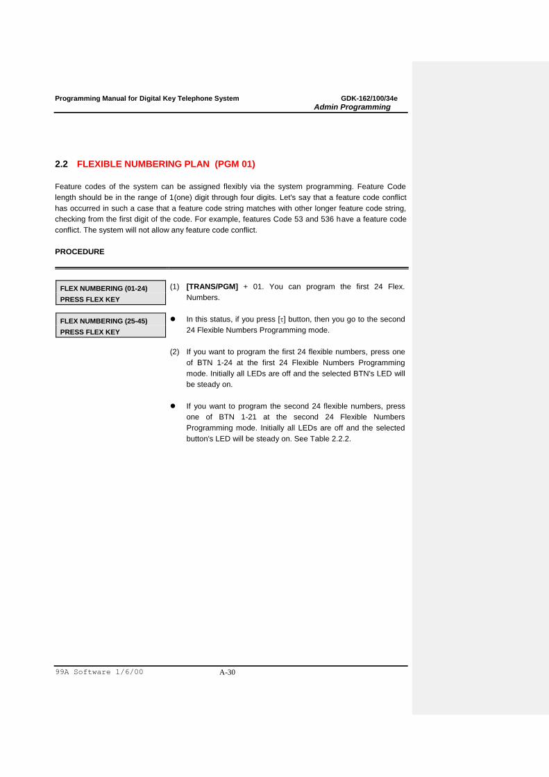
2.2 FLEXIBLE NUMBERING PLAN (PGM 01)
Feature codes of the system can be assigned flexibly via the system programming. Feature Code
length should be in the range of 1(one) digit through four digits. Let's say that a feature code conflict
has occurred in such a case that a feature code string matches with other longer feature code string,
checking from the first digit of the code. For example, features Code 53 and 536 have a feature code
conflict. The system will not allow any feature code conflict.
PROCEDURE
FLEX NUMBERING (01-24)
PRESS FLEX KEY
(1) [TRANS/PGM] + 01. You can program the first 24 Flex.
Numbers.
FLEX NUMBERING (25-45)
PRESS FLEX KEY
In this status, if you press [] button, then you go to the second
24 Flexible Numbers Programming mode.
(2) If you want to program the first 24 flexible numbers, press one
of BTN 1-24 at the first 24 Flexible Numbers Programming
mode. Initially all LEDs are off and the selected BTN's LED will
be steady on.
If you want to program the second 24 flexible numbers, press
one of BTN 1-21 at the second 24 Flexible Numbers
Programming mode. Initially all LEDs are off and the selected
button's LED will be steady on. See Table 2.2.2.
Programming Manual for Digital Key Telephone System GDK-162/100/34e
Admin Programming
99A Software 1/6/00 A-31
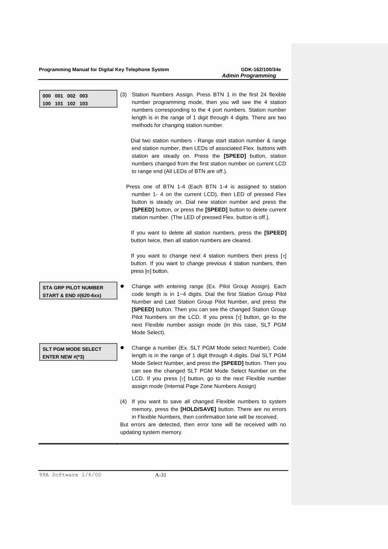
000 001 002 003
100 101 102 103
(3) Station Numbers Assign. Press BTN 1 in the first 24 flexible
number programming mode, then you will see the 4 station
numbers corresponding to the 4 port numbers. Station number
length is in the range of 1 digit through 4 digits. There are two
methods for changing station number.
Dial two station numbers - Range start station number & range
end station number, then LEDs of associated Flex. buttons with
station are steady on. Press the [SPEED] button, station
numbers changed from the first station number on current LCD
to range end (All LEDs of BTN are off.).
Press one of BTN 1-4 (Each BTN 1-4 is assigned to station
number 1- 4 on the current LCD), then LED of pressed Flex
button is steady on. Dial new station number and press the
[SPEED] button, or press the [SPEED] button to delete current
station number. (The LED of pressed Flex. button is off.).
If you want to delete all station numbers, press the [SPEED]
button twice, then all station numbers are cleared.
If you want to change next 4 station numbers then press []
button. If you want to change previous 4 station numbers, then
press [] button.
STA GRP PILOT NUMBER
START & END #(620-6xx)
Change with entering range (Ex. Pilot Group Assign). Each
code length is in 1~4 digits. Dial the first Station Group Pilot
Number and Last Station Group Pilot Number, and press the
[SPEED] button. Then you can see the changed Station Group
Pilot Numbers on the LCD. If you press [] button, go to the
next Flexible number assign mode (in this case, SLT PGM
Mode Select).
SLT PGM MODE SELECT
ENTER NEW #(*3)
Change a number (Ex. SLT PGM Mode select Number). Code
length is in the range of 1 digit through 4 digits. Dial SLT PGM
Mode Select Number, and press the [SPEED] button. Then you
can see the changed SLT PGM Mode Select Number on the
LCD. If you press [] button, go to the next Flexible number
assign mode (Internal Page Zone Numbers Assign)
(4) If you want to save all changed Flexible numbers to system
memory, press the [HOLD/SAVE] button. There are no errors
in Flexible Numbers, then confirmation tone will be received.
But errors are detected, then error tone will be received with no
updating system memory.
Programming Manual for Digital Key Telephone System GDK-162/100/34e
Admin Programming
99A Software 1/6/00 A-32
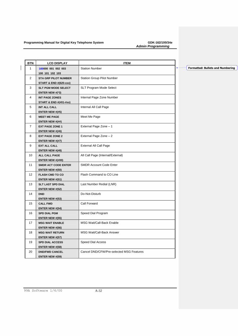
BTN LCD DISPLAY ITEM
1 100000 001 002 003
100 101 102 103
Station Number
2 STA GRP PILOT NUMBER
START & END #(620-xxx)
Station Group Pilot Number
3 SLT PGM MODE SELECT
ENTER NEW #(*3)
SLT Program Mode Select
4 INT PAGE ZONES
START & END #(#01-#xx)
Internal Page Zone Number
5 INT ALL CALL
ENTER NEW #(#5)
Internal All Call Page
6 MEET ME PAGE
ENTER NEW #(##)
Meet Me Page
7 EXT PAGE ZONE 1
ENTER NEW #(#6)
External Page Zone – 1
8 EXT PAGE ZONE 2
ENTER NEW #(#7)
External Page Zone – 2
9 EXT ALL CALL
ENTER NEW #(#8)
External All Call Page
10 ALL CALL PAGE
ENTER NEW #(#00)
All Call Page (Internal/External)
11 SMDR ACT CODE ENTER
ENTER NEW #(50)
SMDR Account Code Enter
12 FLASH CMD TO CO
ENTER NEW #(51)
Flash Command to CO Line
13 SLT LAST SPD DIAL
ENTER NEW #(52)
Last Number Redial (LNR)
14 DND
ENTER NEW #(53)
Do-Not-Disturb
15 CALL FWD
ENTER NEW #(54)
Call Forward
16 SPD DIAL PGM
ENTER NEW #(55)
Speed Dial Program
17 MSG WAIT ENABLE
ENTER NEW #(56)
MSG Wait/Call-Back Enable
18 MSG WAIT RETURN
ENTER NEW #(57)
MSG Wait/Call-Back Answer
19 SPD DIAL ACCESS
ENTER NEW #(58)
Speed Dial Access
20 DND/FWD CANCEL
ENTER NEW #(59)
Cancel DND/CFW/Pre-selected MSG Features
Formatted: Bullets and Numbering
Programming Manual for Digital Key Telephone System GDK-162/100/34e
Admin Programming
99A Software 1/6/00 A-33
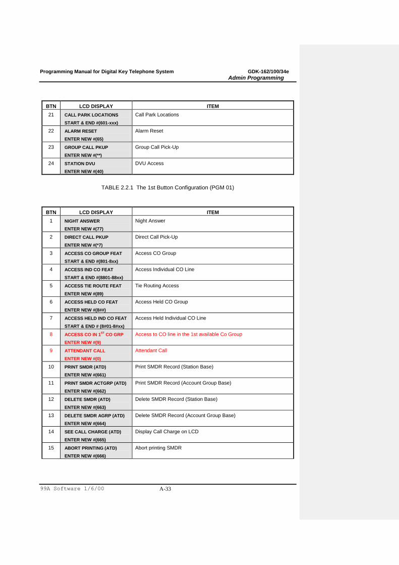
BTN LCD DISPLAY ITEM
21 CALL PARK LOCATIONS
START & END #(601-xxx)
Call Park Locations
22 ALARM RESET
ENTER NEW #(65)
Alarm Reset
23 GROUP CALL PKUP
ENTER NEW #(**)
Group Call Pick-Up
24 STATION DVU
ENTER NEW #(40)
DVU Access
TABLE 2.2.1 The 1st Button Configuration (PGM 01)
BTN LCD DISPLAY ITEM
1 NIGHT ANSWER
ENTER NEW #(77)
Night Answer
2 DIRECT CALL PKUP
ENTER NEW #(*7)
Direct Call Pick-Up
3 ACCESS CO GROUP FEAT
START & END #(801-8xx)
Access CO Group
4 ACCESS IND CO FEAT
START & END #(8801-88xx)
Access Individual CO Line
5 ACCESS TIE ROUTE FEAT
ENTER NEW #(89)
Tie Routing Access
6 ACCESS HELD CO FEAT
ENTER NEW #(8##)
Access Held CO Group
7 ACCESS HELD IND CO FEAT
START & END # (8#01-8#xx)
Access Held Individual CO Line
8 ACCESS CO IN 1ST
CO GRP
ENTER NEW #(9)
Access to CO line in the 1st available Co Group
9 ATTENDANT CALL
ENTER NEW #(0)
Attendant Call
10 PRINT SMDR (ATD)
ENTER NEW #(661)
Print SMDR Record (Station Base)
11 PRINT SMDR ACTGRP (ATD)
ENTER NEW #(662)
Print SMDR Record (Account Group Base)
12 DELETE SMDR (ATD)
ENTER NEW #(663)
Delete SMDR Record (Station Base)
13 DELETE SMDR AGRP (ATD)
ENTER NEW #(664)
Delete SMDR Record (Account Group Base)
14 SEE CALL CHARGE (ATD)
ENTER NEW #(665)
Display Call Charge on LCD
15 ABORT PRINTING (ATD)
ENTER NEW #(666)
Abort printing SMDR
Programming Manual for Digital Key Telephone System GDK-162/100/34e
Admin Programming
99A Software 1/6/00 A-34
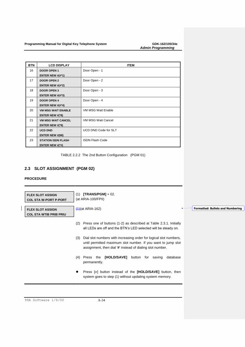
BTN LCD DISPLAY ITEM
16 DOOR OPEN 1
ENTER NEW #(#*1)
Door Open - 1
17 DOOR OPEN 2
ENTER NEW #(#*2)
Door Open - 2
18 DOOR OPEN 3
ENTER NEW #(#*3)
Door Open - 3
19 DOOR OPEN 4
ENTER NEW #(#*4)
Door Open - 4
20 VM MSG WAIT ENABLE
ENTER NEW #(*8)
VM MSG Wait Enable
21 VM MSG WAIT CANCEL
ENTER NEW #(*9)
VM MSG Wait Cancel
22 UCD DND
ENTER NEW #(68)
UCD DND Code for SLT
23 STATION ISDN FLASH
ENTER NEW #(*#)
ISDN Flash Code
TABLE 2.2.2 The 2nd Button Configuration (PGM 01)
2.3 SLOT ASSIGNMENT (PGM 02)
PROCEDURE
FLEX SLOT ASSIGN
COL STA W-PORT P-PORT
(1) [TRANS/PGM] + 02.
(at ARIA-100/FPII)
FLEX SLOT ASSIGN
COL STA WTIB PRIB PRIU
(1)(at ARIA-162)
(2) Press one of buttons (1-2) as described at Table 2.3.1. Initially
all LEDs are off and the BTN‟s LED selected will be steady on.
(3) Dial slot numbers with increasing order for logical slot numbers,
until permitted maximum slot number. If you want to jump slot
assignment, then dial '#' instead of dialing slot number.
(4) Press the [HOLD/SAVE] button for saving database
permanently.
Press [] button instead of the [HOLD/SAVE] button, then
system goes to step (1) without updating system memory.
Formatted: Bullets and Numbering
Programming Manual for Digital Key Telephone System GDK-162/100/34e
Admin Programming
99A Software 1/6/00 A-35
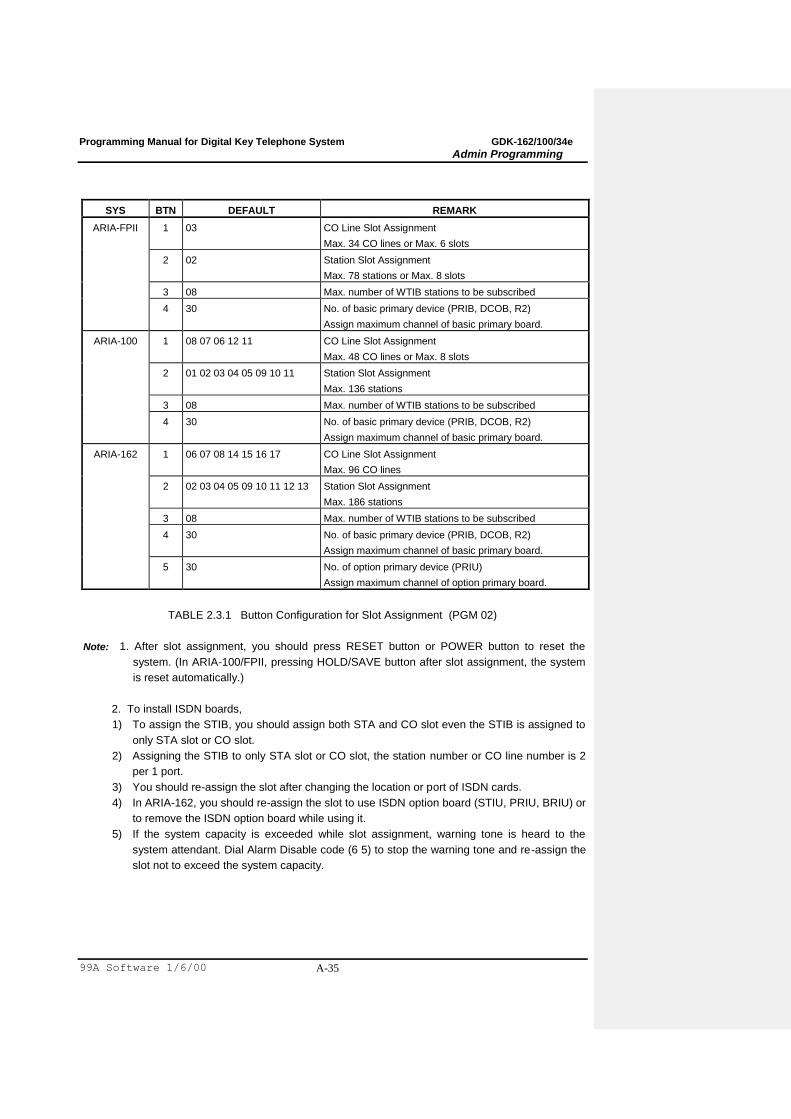
SYS BTN DEFAULT REMARK
ARIA-FPII 1 03 CO Line Slot Assignment
Max. 34 CO lines or Max. 6 slots
2 02 Station Slot Assignment
Max. 78 stations or Max. 8 slots
3 08 Max. number of WTIB stations to be subscribed
4 30 No. of basic primary device (PRIB, DCOB, R2)
Assign maximum channel of basic primary board.
ARIA-100 1 08 07 06 12 11 CO Line Slot Assignment
Max. 48 CO lines or Max. 8 slots
2 01 02 03 04 05 09 10 11 Station Slot Assignment
Max. 136 stations
3 08 Max. number of WTIB stations to be subscribed
4 30 No. of basic primary device (PRIB, DCOB, R2)
Assign maximum channel of basic primary board.
ARIA-162 1 06 07 08 14 15 16 17 CO Line Slot Assignment
Max. 96 CO lines
2 02 03 04 05 09 10 11 12 13 Station Slot Assignment
Max. 186 stations
3 08 Max. number of WTIB stations to be subscribed
4 30 No. of basic primary device (PRIB, DCOB, R2)
Assign maximum channel of basic primary board.
5 30 No. of option primary device (PRIU)
Assign maximum channel of option primary board.
TABLE 2.3.1 Button Configuration for Slot Assignment (PGM 02)
Note: 1. After slot assignment, you should press RESET button or POWER button to reset the
system. (In ARIA-100/FPII, pressing HOLD/SAVE button after slot assignment, the system
is reset automatically.)
2. To install ISDN boards,
1) To assign the STIB, you should assign both STA and CO slot even the STIB is assigned to
only STA slot or CO slot.
2) Assigning the STIB to only STA slot or CO slot, the station number or CO line number is 2
per 1 port.
3) You should re-assign the slot after changing the location or port of ISDN cards.
4) In ARIA-162, you should re-assign the slot to use ISDN option board (STIU, PRIU, BRIU) or
to remove the ISDN option board while using it.
5) If the system capacity is exceeded while slot assignment, warning tone is heard to the
system attendant. Dial Alarm Disable code (6 5) to stop the warning tone and re-assign the
slot not to exceed the system capacity.
Programming Manual for Digital Key Telephone System GDK-162/100/34e
Admin Programming
99A Software 1/6/00 A-36
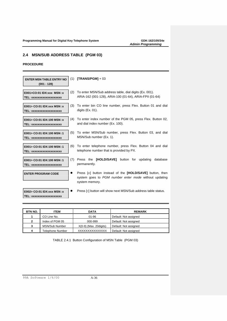
2.4 MSN/SUB ADDRESS TABLE (PGM 03)
PROCEDURE
ENTER MSN TABLE ENTRY NO
(001 - 128)
(1) [TRANS/PGM] + 03
E001>CO:01 IDX:xxx MSN :x
TEL: xxxxxxxxxxxxxxxxxxx
(2) To enter MSN/Sub address table, dial digits (Ex. 001).
ARIA-162 (001-128), ARIA-100 (01-64), ARIA-FPII (01-64)
E001> CO:01 IDX:xxx MSN :x
TEL: xxxxxxxxxxxxxxxxxxx
(3) To enter bin CO line number, press Flex. Button 01 and dial
digits (Ex. 01).
E001> CO:01 IDX:100 MSN :x
TEL: xxxxxxxxxxxxxxxxxxx
(4) To enter index number of the PGM 05, press Flex. Button 02,
and dial index number (Ex. 100).
E001> CO:01 IDX:100 MSN :1
TEL: xxxxxxxxxxxxxxxxxxx
(5) To enter MSN/Sub number, press Flex. Button 03, and dial
MSN/Sub number (Ex. 1).
E001> CO:01 IDX:100 MSN :1
TEL: xxxxxxxxxxxxxxxxxxx
(6) To enter telephone number, press Flex. Button 04 and dial
telephone number that is provided by PX.
E001> CO:01 IDX:100 MSN :1
TEL: xxxxxxxxxxxxxxxxxxx
(7) Press the [HOLD/SAVE] button for updating database
permanently.
ENTER PROGRAM CODE
Press [] button instead of the [HOLD/SAVE] button, then
system goes to PGM number enter mode without updating
system memory.
E002> CO:01 IDX:xxx MSN :x
TEL: xxxxxxxxxxxxxxxxxxx
Press [] button will show next MSN/Sub address table status.
BTN NO. ITEM DATA REMARK
1 CO Line No. 01-96 Default: Not assigned
2 Index of PGM 05 000-999 Default: Not assigned
3 MSN/Sub Number X(0-9) (Max. 20digits) Default: Not assigned
4 Telephone Number XXXXXXXXXXXXXXX Default: Not assigned
TABLE 2.4.1 Button Configuration of MSN Table (PGM 03)
Programming Manual for Digital Key Telephone System GDK-162/100/34e
Admin Programming
99A Software 1/6/00 A-37
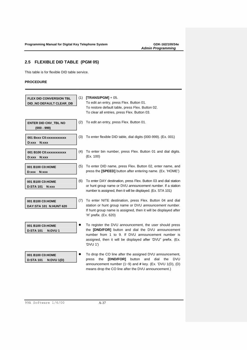
2.5 FLEXIBLE DID TABLE (PGM 05)
This table is for flexible DID table service.
PROCEDURE
FLEX DID CONVERSION TBL
DID_NO DEFAULT CLEAR_DB
(1) [TRANS/PGM] + 05.
To edit an entry, press Flex. Button 01.
To restore default table, press Flex. Button 02.
To clear all entries, press Flex. Button 03.
ENTER DID CNV_TBL NO
(000 - 999)
(2) To edit an entry, press Flex. Button 01.
001 Bxxx C0:xxxxxxxxxxx
D:xxx N:xxx
(3) To enter flexible DID table, dial digits (000-999). (Ex. 001)
001 B100 C0:xxxxxxxxxxx
D:xxx N:xxx
(4) To enter bin number, press Flex. Button 01 and dial digits.
(Ex. 100)
001 B100 C0:HOME
D:xxx N:xxx
(5) To enter DID name, press Flex. Button 02, enter name, and
press the [SPEED] button after entering name. (Ex. 'HOME')
001 B100 C0:HOME
D:STA 101 N:xxx
(6) To enter DAY destination, press Flex. Button 03 and dial station
or hunt group name or DVU announcement number. If a station
number is assigned, then it will be displayed. (Ex. STA 101)
001 B100 C0:HOME
DAY:STA 101 N:HUNT 620
(7) To enter NITE destination, press Flex. Button 04 and dial
station or hunt group name or DVU announcement number.
If hunt group name is assigned, then it will be displayed after
„H‟ prefix. (Ex. 620)
001 B100 C0:HOME
D:STA 101 N:DVU 1
To register the DVU announcement, the user should press
the [DND/FOR] button and dial the DVU announcement
number from 1 to 9. If DVU announcement number is
assigned, then it will be displayed after „DVU” prefix. (Ex.
'DVU 1')
001 B100 C0:HOME
D:STA 101 N:DVU 1(D)
To drop the CO line after the assigned DVU announcement,
press the [DND/FOR] button and dial the DVU
announcement number (1~9) and # key. (Ex. „DVU 1(D), (D)
means drop the CO line after the DVU announcement.)
Programming Manual for Digital Key Telephone System GDK-162/100/34e
Admin Programming
99A Software 1/6/00 A-38
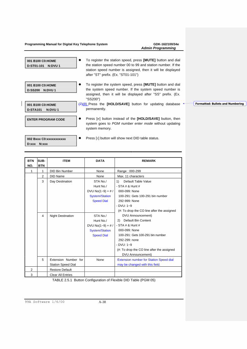
001 B100 C0:HOME
D:ST01-101 N:DVU 1
To register the station speed, press [MUTE] button and dial
the station speed number 00 to 99 and station number. If the
station speed number is assigned, then it will be displayed
after "ST" prefix. (Ex. "ST01-101")
001 B100 C0:HOME
D:SS200 N:DVU 1
To register the system speed, press [MUTE] button and dial
the system speed number. If the system speed number is
assigned, then it will be displayed after "SS" prefix. (Ex.
"SS200")
001 B100 C0:HOME
D:STA101 N:DVU 1
(7)(8) Press the [HOLD/SAVE] button for updating database
permanently.
ENTER PROGRAM CODE
Press [] button instead of the [HOLD/SAVE] button, then
system goes to PGM number enter mode without updating
system memory.
002 Bxxx C0:xxxxxxxxxxx
D:xxx N:xxx
Press [] button will show next DID table status.
BTN
NO.
SUB-
BTN
ITEM DATA REMARK
1 1 DID Bin Number None Range : 000-299
2 DID Name None Max. 11 characters
3 Day Destination STA No./
Hunt No./
DVU No(1~9) + # /
System/Station
Speed Dial
1) Default Table Value
- STA # & Hunt #
000-099: None
100-291: Gets 100-291 bin number
292-999: None
- DVU: 1~9
(#: To drop the CO line after the assigned
DVU Announcement)
2) Default Bin Content
- STA # & Hunt #
000-099: None
100-291: Gets 100-291 bin number
292-299: none
- DVU: 1~9
(#: To drop the CO line after the assigned
DVU Announcement)
4 Night Destination STA No./
Hunt No./
DVU No(1~9) + # /
System/Station
Speed Dial
5 Extension Number for
Station Speed Dial
None Extension number for Station Speed dial
may be changed with this field.
2 Restore Default
3 Clear All Entries
TABLE 2.5.1 Button Configuration of Flexible DID Table (PGM 05)
Formatted: Bullets and Numbering

Programming Manual for Digital Key Telephone System GDK-162/100/34e
Admin Programming
99A Software 1/6/00 A-39
2.6 EMERGENCY CALL (PGM 06)
The table is for emergency call service. A station that has lower COS can dial emergency call. (The
applying priority in ARIA is LCR -> Numbering Plan -> Emergency Call Number.)
PROCEDURE
EMERGENCY SVC CALL
PRESS FLEX KEY BUTTON 1-10
(1) [TRANS/PGM] + 06
EMERGENCY SVC CALL
BIN 01: E
(2) To enter Emergency, enter Flex. Button (1~10)
EMERGENCY SVC CALL
BIN 01: 00119E
(3) To assign emergency call number, dial the digits (Ex. 00119).
EMERGENCY SVC CALL
BIN 01: 00119E
(4) Press the [HOLD/SAVE] button for updating database
permanently.
ENTER PROGRAM CODE
Press [] button instead of the [HOLD/SAVE] button, then
system goes to PGM number enter mode without updating
system memory.
Programming Manual for Digital Key Telephone System GDK-162/100/34e
Admin Programming
99A Software 1/6/00 A-40
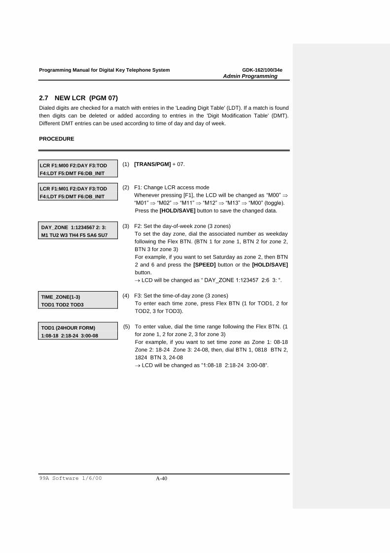
2.7 NEW LCR (PGM 07)
Dialed digits are checked for a match with entries in the 'Leading Digit Table' (LDT). If a match is found
then digits can be deleted or added according to entries in the 'Digit Modification Table' (DMT).
Different DMT entries can be used according to time of day and day of week.
PROCEDURE
LCR F1:M00 F2:DAY F3:TOD
F4:LDT F5:DMT F6:DB_INIT
(1) [TRANS/PGM] + 07.
LCR F1:M01 F2:DAY F3:TOD
F4:LDT F5:DMT F6:DB_INIT
(2) F1: Change LCR access mode
Whenever pressing [F1], the LCD will be changed as “M00”
“M01” “M02” “M11” “M12” “M13” “M00” (toggle).
Press the [HOLD/SAVE] button to save the changed data.
DAY_ZONE 1:1234567 2: 3:
M1 TU2 W3 TH4 F5 SA6 SU7
(3) F2: Set the day-of-week zone (3 zones)
To set the day zone, dial the associated number as weekday
following the Flex BTN. (BTN 1 for zone 1, BTN 2 for zone 2,
BTN 3 for zone 3)
For example, if you want to set Saturday as zone 2, then BTN
2 and 6 and press the [SPEED] button or the [HOLD/SAVE]
button.
LCD will be changed as “ DAY_ZONE 1:123457 2:6 3: “.
TIME_ZONE(1-3)
TOD1 TOD2 TOD3
(4) F3: Set the time-of-day zone (3 zones)
To enter each time zone, press Flex BTN (1 for TOD1, 2 for
TOD2, 3 for TOD3).
TOD1 (24HOUR FORM)
1:08-18 2:18-24 3:00-08
(5) To enter value, dial the time range following the Flex BTN. (1
for zone 1, 2 for zone 2, 3 for zone 3)
For example, if you want to set time zone as Zone 1: 08-18
Zone 2: 18-24 Zone 3: 24-08, then, dial BTN 1, 0818 BTN 2,
1824 BTN 3, 24-08
LCD will be changed as “1:08-18 2:18-24 3:00-08“.
Programming Manual for Digital Key Telephone System GDK-162/100/34e
Admin Programming
99A Software 1/6/00 A-41
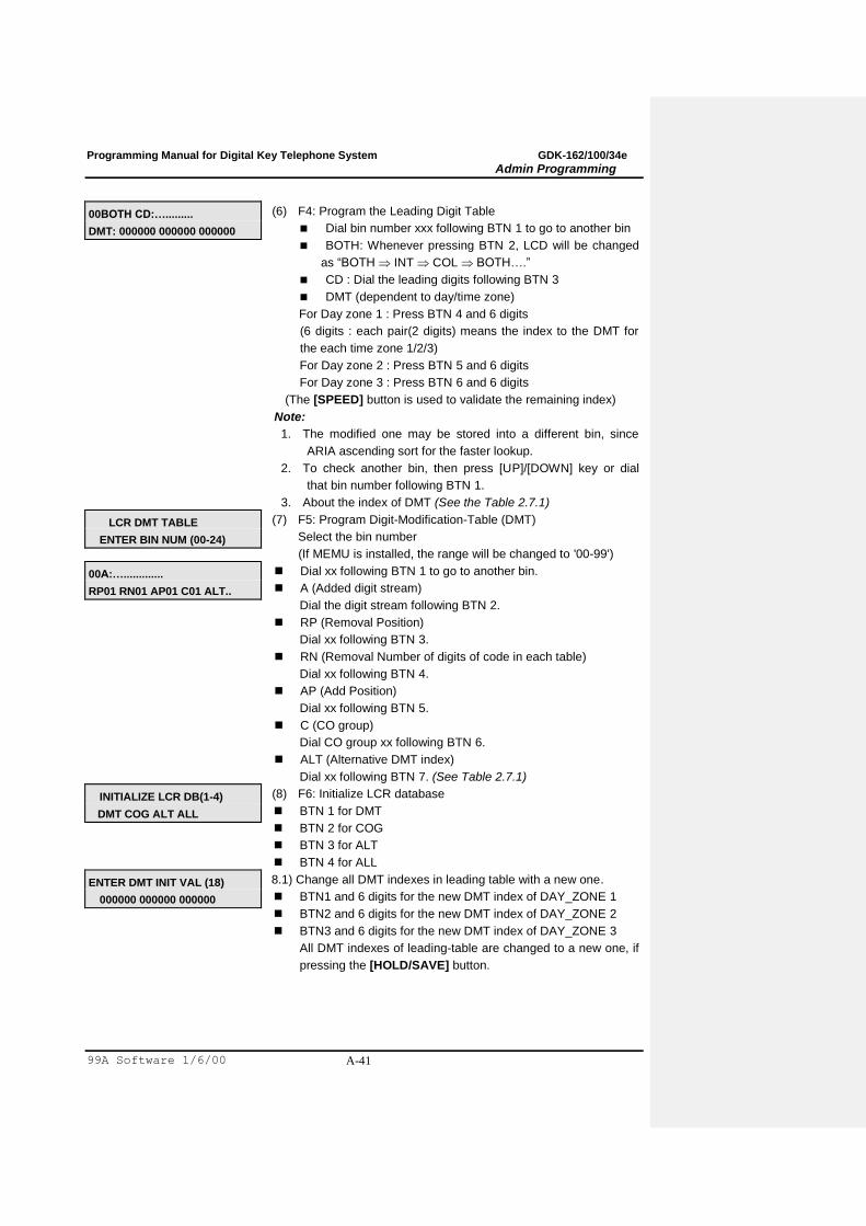
00BOTH CD:….........
DMT: 000000 000000 000000
(6) F4: Program the Leading Digit Table
Dial bin number xxx following BTN 1 to go to another bin
BOTH: Whenever pressing BTN 2, LCD will be changed
as “BOTH INT COL BOTH….”
CD : Dial the leading digits following BTN 3
DMT (dependent to day/time zone)
For Day zone 1 : Press BTN 4 and 6 digits
(6 digits : each pair(2 digits) means the index to the DMT for
the each time zone 1/2/3)
For Day zone 2 : Press BTN 5 and 6 digits
For Day zone 3 : Press BTN 6 and 6 digits
(The [SPEED] button is used to validate the remaining index)
Note:
1. The modified one may be stored into a different bin, since
ARIA ascending sort for the faster lookup.
2. To check another bin, then press [UP]/[DOWN] key or dial
that bin number following BTN 1.
3. About the index of DMT (See the Table 2.7.1)
LCR DMT TABLE
ENTER BIN NUM (00-24)
(7) F5: Program Digit-Modification-Table (DMT)
Select the bin number
(If MEMU is installed, the range will be changed to '00-99')
00A:….............
RP01 RN01 AP01 C01 ALT..
Dial xx following BTN 1 to go to another bin.
A (Added digit stream)
Dial the digit stream following BTN 2.
RP (Removal Position)
Dial xx following BTN 3.
RN (Removal Number of digits of code in each table)
Dial xx following BTN 4.
AP (Add Position)
Dial xx following BTN 5.
C (CO group)
Dial CO group xx following BTN 6.
ALT (Alternative DMT index)
Dial xx following BTN 7. (See Table 2.7.1)
INITIALIZE LCR DB(1-4)
DMT COG ALT ALL
(8) F6: Initialize LCR database
BTN 1 for DMT
BTN 2 for COG
BTN 3 for ALT
BTN 4 for ALL
ENTER DMT INIT VAL (18)
000000 000000 000000
8.1) Change all DMT indexes in leading table with a new one.
BTN1 and 6 digits for the new DMT index of DAY_ZONE 1
BTN2 and 6 digits for the new DMT index of DAY_ZONE 2
BTN3 and 6 digits for the new DMT index of DAY_ZONE 3
All DMT indexes of leading-table are changed to a new one, if
pressing the [HOLD/SAVE] button.
Programming Manual for Digital Key Telephone System GDK-162/100/34e
Admin Programming
99A Software 1/6/00 A-42
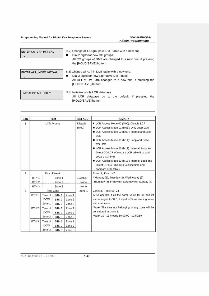
ENTER CO_GRP INIT VAL
..
8.2) Change all CO groups in DMT table with a new one.
Dial 2 digits for new CO groups.
All CO groups of DMT are changed to a new one, if pressing
the [HOLD/SAVE] button.
ENTER ALT_INDEX INIT VAL
..
8.3) Change all ALT in DMT table with a new one.
Dial 2 digits for new alternative DMT index.
All ALT of DMT are changed to a new one, if pressing the
[HOLD/SAVE] button.
INITIALIZE ALL LCR ?
8.4) Initialize whole LCR database
All LCR database go to the default, if pressing the
[HOLD/SAVE] button.
BTN ITEM DEFAULT REMARK
1 LCR Access Disable
(M00)
LCR Access Mode 00 (M00): Disable LCR
LCR Access Mode 01 (M01): Only Loop LCR
LCR Access Mode 02 (M02): Internal and Loop
LCR
LCR Access Mode 11 (M11): Loop and Direct
CO LCR
LCR Access Mode 12 (M12): Internal, Loop and
Direct CO LCR (Compare LCR table first, and
seize a CO line)
LCR Access Mode 13 (M13): Internal, Loop and
Direct CO LCR (Seize a CO line first, and
compare LCR table)
2 Day of Week Zone: 3, Day: 1~7
* Monday (1), Tuesday (2), Wednesday (3)
Thursday (4), Friday (5), Saturday (6), Sunday (7)
BTN 1 Zone 1 1234567
BTN 2 Zone 2 None
BTN 3 Zone 3 None
3 Time Zone Zone 1 Zone: 3, Time: 00~24
ARIA accepts it as the same value for 00 and 24
and changes to “00”, if input is 24 as starting value
and vice versa.
*Note: The time not belonging to any zone will be
considered as zone 1.
*Note: 10 - 13 means 10:00:00 - 12:59:59
BTN 1 Time of
DOW
Zone 1
BTN 1 Zone 1
BTN 2 Zone 2
BTN 3 Zone 3
BTN 2 Time of
DOW
Zone 2
BTN 1 Zone 1
BTN 2 Zone 2
BTN 3 Zone 3
BTN 3 Time of
DOW
Zone 3
BTN 1 Zone 1
BTN 2 Zone 2
BTN 3 Zone 3
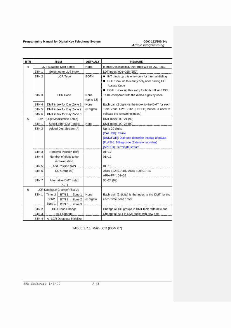
Programming Manual for Digital Key Telephone System GDK-162/100/34e
Admin Programming
99A Software 1/6/00 A-43
BTN ITEM DEFAULT REMARK
4 LDT (Leading Digit Table) None If MEMU is installed, the range will be 001 - 250
BTN 1 Select other LDT Index LDT Index: 001~025 (250)
BTN 2 LCR Type BOTH INT : look up this entry only for internal dialing
COL : look up this entry only after dialing CO
Access Code
BOTH : look up this entry for both INT and COL
BTN 3 LCR Code None
(up to 12)
To be compared with the dialed digits by user.
BTN 4 DMT index for Day Zone 1 None
(6 digits)
Each pair (2 digits) is the index to the DMT for each
Time Zone 1/2/3. (The [SPEED] button is used to
validate the remaining index.)
BTN 5 DMT index for Day Zone 2
BTN 6 DMT index for Day Zone 3
5 DMT (Digit Modification Table) DMT Index: 00~24 (99)
BTN 1 Select other DMT Index None DMT Index: 00~24 (99)
BTN 2 Added Digit Stream (A) Up to 20 digits
[CALLBK]: Pause
[DND/FOR]: Dial tone detection instead of pause
[FLASH]: Billing code (Extension number)
[SPEED]: Terminate stream
BTN 3 Removal Position (RP) 01~12
BTN 4 Number of digits to be
removed (RN)
01~12
BTN 5 Add Position (AP) 01~13
BTN 6 CO Group (C) ARIA-162: 01~48 / ARIA-100: 01~24
ARIA-FPII: 01~09
BTN 7 Alternative DMT Index
(ALT)
00~24 (99)
6 LCR Database Change/Initialize
BTN 1 Time of
DOW
Zone 1
BTN 1 Zone 1 None
(6 digits)
Each pair (2 digits) is the index to the DMT for the
each Time Zone 1/2/3. BTN 2 Zone 2
BTN 3 Zone 3
BTN 2 CO Group Change Change all CO groups in DMT table with new one
BTN 3 ALT Change Change all ALT in DMT table with new one
BTN 4 All LCR Database Initialize
TABLE 2.7.1 Main LCR (PGM 07)
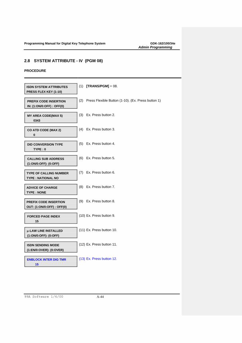
Programming Manual for Digital Key Telephone System GDK-162/100/34e
Admin Programming
99A Software 1/6/00 A-44
2.8 SYSTEM ATTRIBUTE - IV (PGM 08)
PROCEDURE
ISDN SYSTEM ATTRIBUTES
PRESS FLEX KEY (1-10)
(1) [TRANS/PGM] + 08.
PREFIX CODE INSERTION
IN: (1:ON/0:OFF) : OFF(0)
(2) Press Flexible Button (1-10). (Ex. Press button 1)
MY AREA CODE(MAX 5)
0343
(3) Ex. Press button 2.
CO ATD CODE (MAX 2)
0
(4) Ex. Press button 3.
DID CONVERSION TYPE
TYPE : 0
(5) Ex. Press button 4.
CALLING SUB ADDRESS
(1:ON/0:OFF): (0:OFF)
(6) Ex. Press button 5.
TYPE OF CALLING NUMBER
TYPE : NATIONAL NO
(7) Ex. Press button 6.
ADVICE OF CHARGE
TYPE : NONE
(8) Ex. Press button 7.
PREFIX CODE INSERTION
OUT: (1:ON/0:OFF) : OFF(0)
(9) Ex. Press button 8.
FORCED PAGE INDEX
15
(10) Ex. Press button 9.
-LAW LINE INSTALLED
(1:ON/0:OFF): (0:OFF)
(11) Ex. Press button 10.
ISDN SENDING MODE
(1:EN/0:OVER): (0:OVER)
(12) Ex. Press button 11.
ENBLOCK INTER DIG TMR
15
(13) Ex. Press button 12.
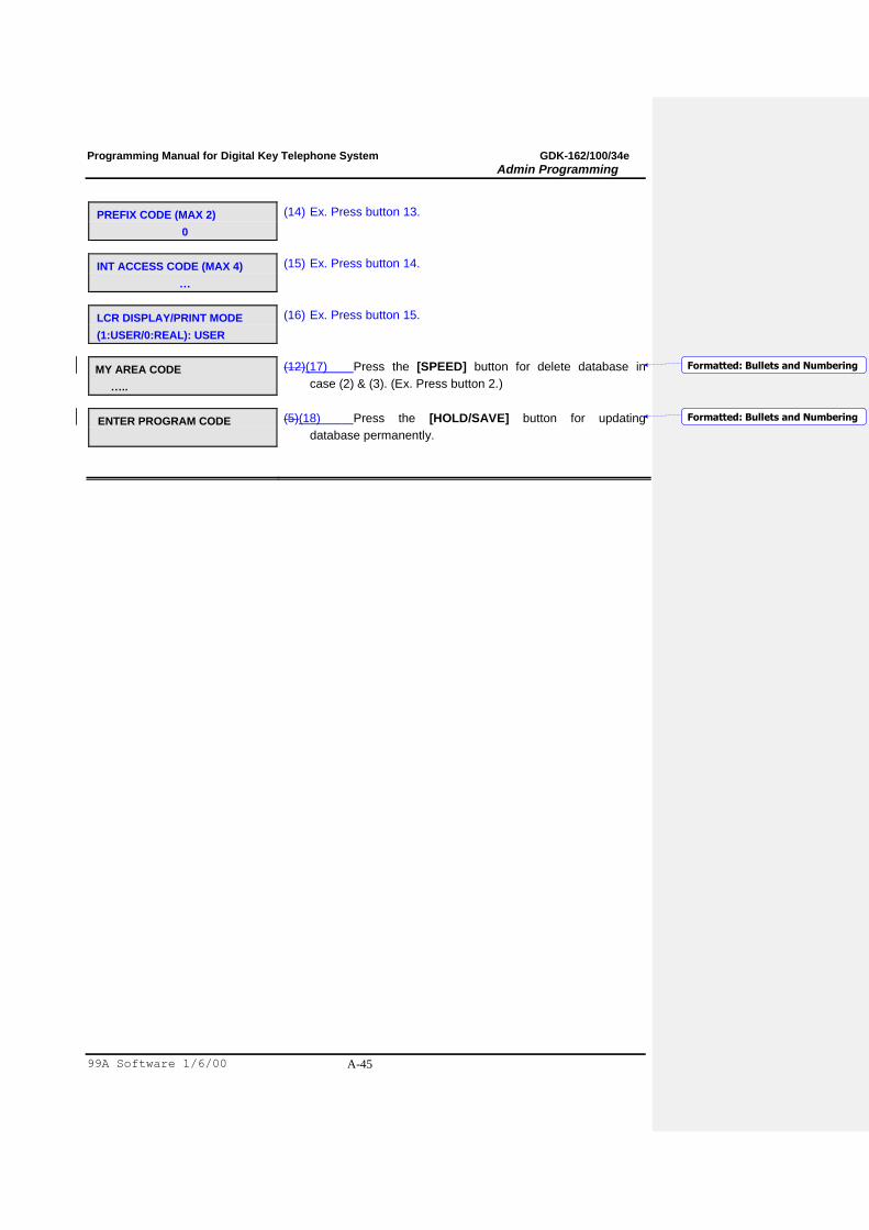
Programming Manual for Digital Key Telephone System GDK-162/100/34e
Admin Programming
99A Software 1/6/00 A-45
PREFIX CODE (MAX 2)
0
(14) Ex. Press button 13.
INT ACCESS CODE (MAX 4)
…
(15) Ex. Press button 14.
LCR DISPLAY/PRINT MODE
(1:USER/0:REAL): USER
(16) Ex. Press button 15.
MY AREA CODE
…..
(12)(17) Press the [SPEED] button for delete database in
case (2) & (3). (Ex. Press button 2.)
ENTER PROGRAM CODE
(5)(18) Press the [HOLD/SAVE] button for updating
database permanently.
Formatted: Bullets and Numbering
Formatted: Bullets and Numbering
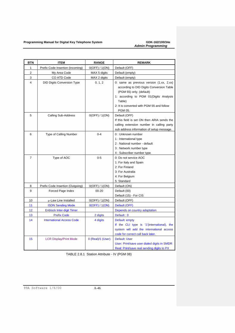
Programming Manual for Digital Key Telephone System GDK-162/100/34e
Admin Programming
99A Software 1/6/00 A-46
BTN ITEM RANGE REMARK
1 Prefix Code Insertion (incoming) 0(OFF) / 1(ON) Default (OFF)
2 My Area Code MAX 5 digits Default (empty)
3 CO ATD Code MAX 2 digits Default (empty)
4 DID Digits Conversion Type 0, 1, 2 0: same as previous version (1.xx, 2.xx)
according to DID Digits Conversion Table
(PGM 55) only. (default)
1: according to PGM 01(Digits Analysis
Table)
2: It is converted with PGM 55 and follow
PGM 05.
5 Calling Sub-Address 0(OFF) / 1(ON) Default (OFF)
If this field is set ON then ARIA sends the
calling extension number in calling party
sub address information of setup message.
6 Type of Calling Number 0-4 0 : Unknown number
1 : International type
2 : National number - default
3 : Network number type
4 : Subscriber number type
7 Type of AOC 0-5 0: Do not service AOC
1: For Italy and Spain
2: For Finland
3: For Australia
4: For Belgium
5: Standard
8 Prefix Code Insertion (Outgoing) 0(OFF) / 1(ON) Default (ON)
9 Forced Page Index 00-20 Default (00)
Default (15) - For CIS
10 -Law Line Installed 0(OFF) / 1(ON) Default (OFF)
11 ISDN Sending Mode 0(OFF) / 1(ON) Default (OFF)
12 Enblock Inter-digit Timer Depends on country adaptation
13 Prefix Code 2 digits Default : 0
14 International Access Code 4 digits Default: empty
If the CLI type is „1‟(international), the
system will add the international access
code for correct call back later.
15 LCR Display/Print Mode 0 (Real)/1 (User) Default: User
User: Print/save user dialed digits in SMDR
Real: Print/save real sending digits to PX
TABLE 2.8.1 Station Attribute - IV (PGM 08)
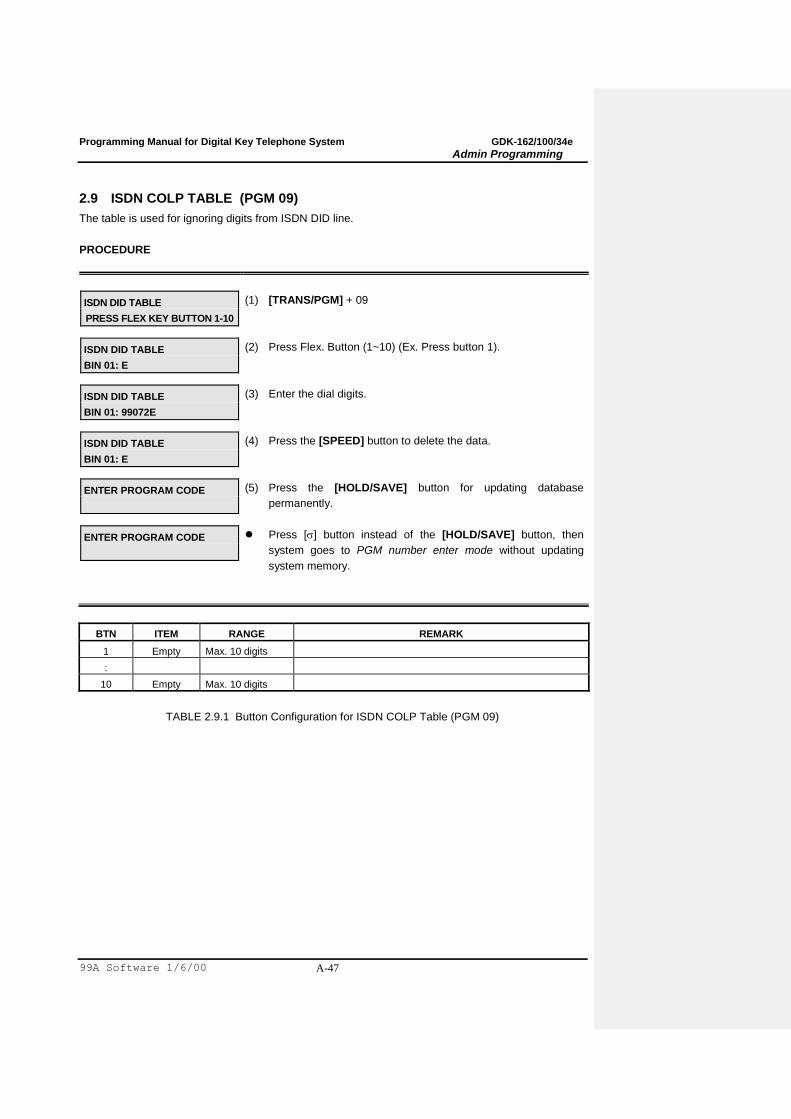
Programming Manual for Digital Key Telephone System GDK-162/100/34e
Admin Programming
99A Software 1/6/00 A-47
2.9 ISDN COLP TABLE (PGM 09)
The table is used for ignoring digits from ISDN DID line.
PROCEDURE
ISDN DID TABLE
PRESS FLEX KEY BUTTON 1-10
(1) [TRANS/PGM] + 09
ISDN DID TABLE
BIN 01: E
(2) Press Flex. Button (1~10) (Ex. Press button 1).
ISDN DID TABLE
BIN 01: 99072E
(3) Enter the dial digits.
ISDN DID TABLE
BIN 01: E
(4) Press the [SPEED] button to delete the data.
ENTER PROGRAM CODE
(5) Press the [HOLD/SAVE] button for updating database
permanently.
ENTER PROGRAM CODE
Press [] button instead of the [HOLD/SAVE] button, then
system goes to PGM number enter mode without updating
system memory.
BTN ITEM RANGE REMARK
1 Empty Max. 10 digits
:
10 Empty Max. 10 digits
TABLE 2.9.1 Button Configuration for ISDN COLP Table (PGM 09)
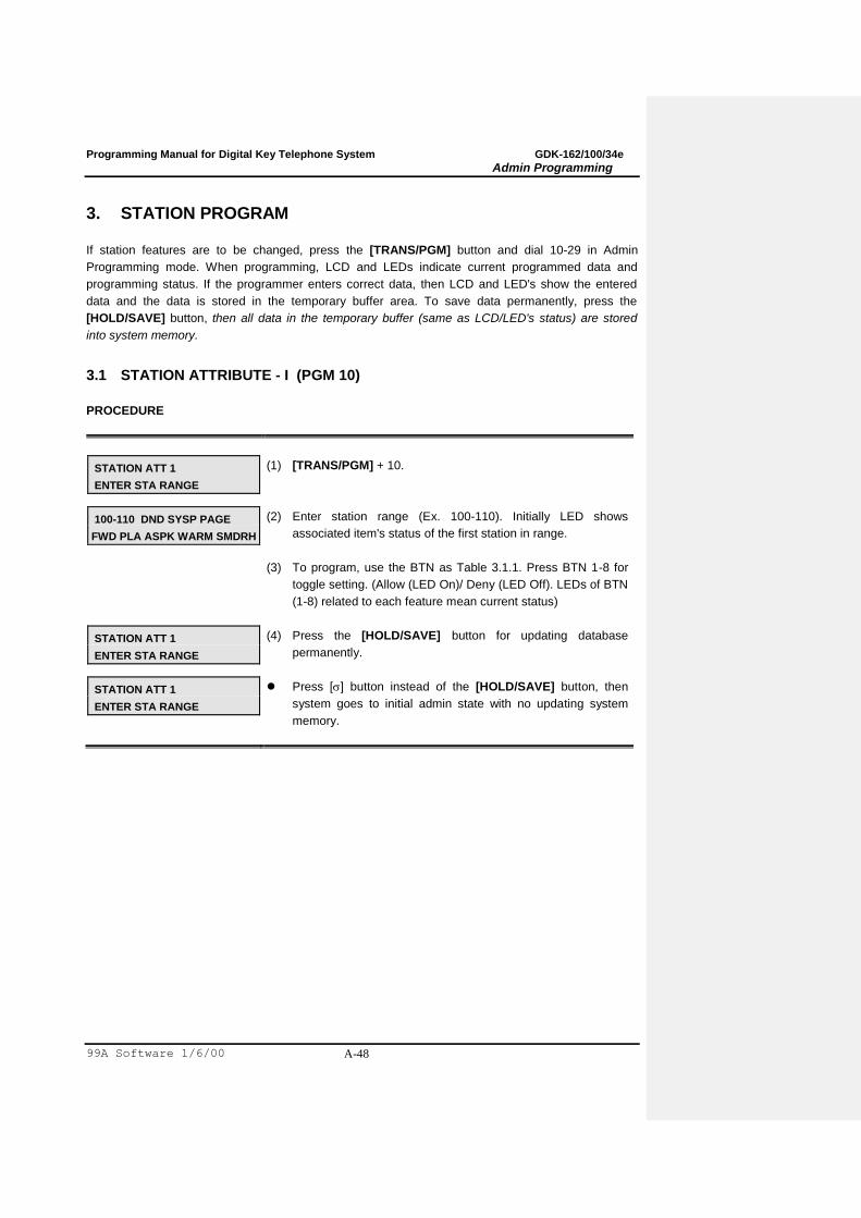
Programming Manual for Digital Key Telephone System GDK-162/100/34e
Admin Programming
99A Software 1/6/00 A-48
3. STATION PROGRAM
If station features are to be changed, press the [TRANS/PGM] button and dial 10-29 in Admin
Programming mode. When programming, LCD and LEDs indicate current programmed data and
programming status. If the programmer enters correct data, then LCD and LED's show the entered
data and the data is stored in the temporary buffer area. To save data permanently, press the
[HOLD/SAVE] button, then all data in the temporary buffer (same as LCD/LED's status) are stored
into system memory.
3.1 STATION ATTRIBUTE - I (PGM 10)
PROCEDURE
STATION ATT 1
ENTER STA RANGE
(1) [TRANS/PGM] + 10.
100-110 DND SYSP PAGE
FWD PLA ASPK WARM SMDRH
(2) Enter station range (Ex. 100-110). Initially LED shows
associated item's status of the first station in range.
(3) To program, use the BTN as Table 3.1.1. Press BTN 1-8 for
toggle setting. (Allow (LED On)/ Deny (LED Off). LEDs of BTN
(1-8) related to each feature mean current status)
STATION ATT 1
ENTER STA RANGE
(4) Press the [HOLD/SAVE] button for updating database
permanently.
STATION ATT 1
ENTER STA RANGE
Press [] button instead of the [HOLD/SAVE] button, then
system goes to initial admin state with no updating system
memory.

Programming Manual for Digital Key Telephone System GDK-162/100/34e
Admin Programming
99A Software 1/6/00 A-49
BTN ITEM DEFAULT (LED) REMARK
1 DND YES (ON) Enables DND to be activated by the station.
2 Speed Dial Access YES (ON) Allows access to system and station speed dial by the station.
3 Page Access YES (ON) Allows access to paging by the station.
4 Call Forward NO (OFF) Enables Call Forward to be activated by the station.
5 PLA YES (ON) The allowance to answer calls by simply lifting handset or
pressing the [MON] button with the answering priority.
6 Auto Speaker YES (ON) The allowance to access a CO line or place a DSS call by
pressing appropriate {CO} or {DSS} button without lifting
handset or pressing the [MON] button.
7 Warm Line NO (OFF) The allowance that the user lifts handset or presses [MON]
button, and user takes no further action for warm line timer,
then idle line selection for warm line is activated.
8 SMDR Hidden
Dialed Digits
NO (OFF) The allowance to hide CO dialing number on SMDR printing.
TABLE 3.1.1 Button Configuration (PGM 10)
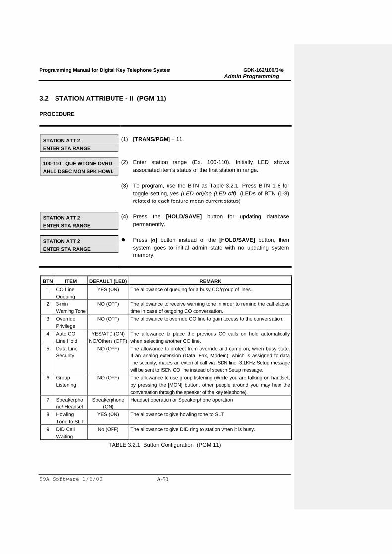
Programming Manual for Digital Key Telephone System GDK-162/100/34e
Admin Programming
99A Software 1/6/00 A-50
3.2 STATION ATTRIBUTE - II (PGM 11)
PROCEDURE
STATION ATT 2
ENTER STA RANGE
(1) [TRANS/PGM] + 11.
100-110 QUE WTONE OVRD
AHLD DSEC MON SPK HOWL
(2) Enter station range (Ex. 100-110). Initially LED shows
associated item's status of the first station in range.
(3) To program, use the BTN as Table 3.2.1. Press BTN 1-8 for
toggle setting, yes (LED on)/no (LED off). (LEDs of BTN (1-8)
related to each feature mean current status)
STATION ATT 2
ENTER STA RANGE
(4) Press the [HOLD/SAVE] button for updating database
permanently.
STATION ATT 2
ENTER STA RANGE
Press [] button instead of the [HOLD/SAVE] button, then
system goes to initial admin state with no updating system
memory.
BTN ITEM DEFAULT (LED) REMARK
1 CO Line
Queuing
YES (ON) The allowance of queuing for a busy CO/group of lines.
2 3-min
Warning Tone
NO (OFF) The allowance to receive warning tone in order to remind the call elapse
time in case of outgoing CO conversation.
3 Override
Privilege
NO (OFF) The allowance to override CO line to gain access to the conversation.
4 Auto CO
Line Hold
YES/ATD (ON)
NO/Others (OFF)
The allowance to place the previous CO calls on hold automatically
when selecting another CO line.
5 Data Line
Security
NO (OFF) The allowance to protect from override and camp-on, when busy state.
If an analog extension (Data, Fax, Modem), which is assigned to data
line security, makes an external call via ISDN line, 3.1KHz Setup message
will be sent to ISDN CO line instead of speech Setup message.
6 Group
Listening
NO (OFF) The allowance to use group listening (While you are talking on handset,
by pressing the [MON] button, other people around you may hear the
conversation through the speaker of the key telephone).
7 Speakerpho
ne/ Headset
Speakerphone
(ON)
Headset operation or Speakerphone operation
8 Howling
Tone to SLT
YES (ON) The allowance to give howling tone to SLT
9 DID Call
Waiting
No (OFF) The allowance to give DID ring to station when it is busy.
TABLE 3.2.1 Button Configuration (PGM 11)
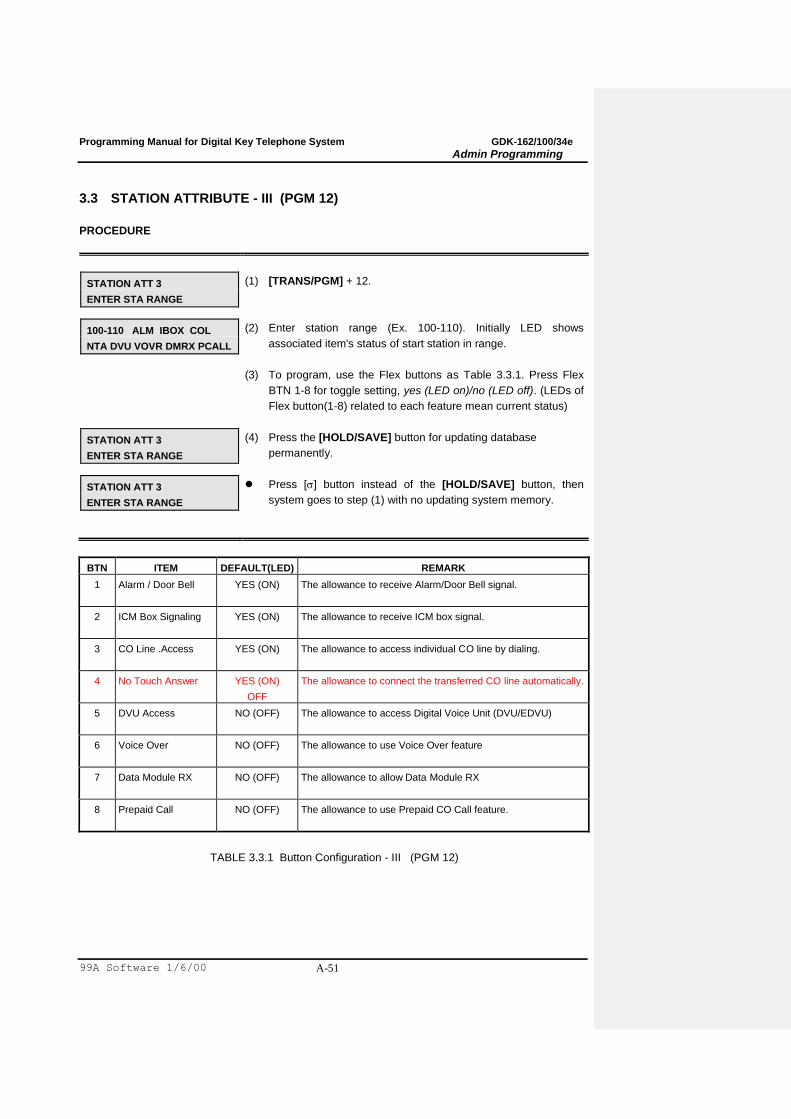
Programming Manual for Digital Key Telephone System GDK-162/100/34e
Admin Programming
99A Software 1/6/00 A-51
3.3 STATION ATTRIBUTE - III (PGM 12)
PROCEDURE
STATION ATT 3
ENTER STA RANGE
(1) [TRANS/PGM] + 12.
100-110 ALM IBOX COL
NTA DVU VOVR DMRX PCALL
(2) Enter station range (Ex. 100-110). Initially LED shows
associated item's status of start station in range.
(3) To program, use the Flex buttons as Table 3.3.1. Press Flex
BTN 1-8 for toggle setting, yes (LED on)/no (LED off). (LEDs of
Flex button(1-8) related to each feature mean current status)
STATION ATT 3
ENTER STA RANGE
(4) Press the [HOLD/SAVE] button for updating database
permanently.
STATION ATT 3
ENTER STA RANGE
Press [] button instead of the [HOLD/SAVE] button, then
system goes to step (1) with no updating system memory.
BTN ITEM DEFAULT(LED) REMARK
1 Alarm / Door Bell YES (ON) The allowance to receive Alarm/Door Bell signal.
2 ICM Box Signaling YES (ON) The allowance to receive ICM box signal.
3 CO Line .Access YES (ON) The allowance to access individual CO line by dialing.
4 No Touch Answer YES (ON)
OFF
The allowance to connect the transferred CO line automatically.
5 DVU Access NO (OFF) The allowance to access Digital Voice Unit (DVU/EDVU)
6 Voice Over NO (OFF) The allowance to use Voice Over feature
7 Data Module RX NO (OFF) The allowance to allow Data Module RX
8 Prepaid Call NO (OFF) The allowance to use Prepaid CO Call feature.
TABLE 3.3.1 Button Configuration - III (PGM 12)
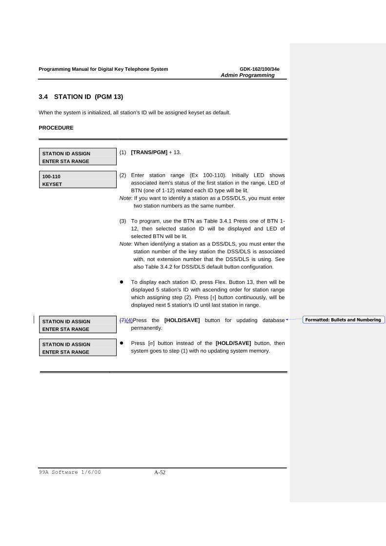
Programming Manual for Digital Key Telephone System GDK-162/100/34e
Admin Programming
99A Software 1/6/00 A-52
3.4 STATION ID (PGM 13)
When the system is initialized, all station's ID will be assigned keyset as default.
PROCEDURE
STATION ID ASSIGN
ENTER STA RANGE
(1) [TRANS/PGM] + 13.
100-110
KEYSET
(2) Enter station range (Ex 100-110). Initially LED shows
associated item's status of the first station in the range. LED of
BTN (one of 1-12) related each ID type will be lit.
Note: If you want to identify a station as a DSS/DLS, you must enter
two station numbers as the same number.
(3) To program, use the BTN as Table 3.4.1 Press one of BTN 1-
12, then selected station ID will be displayed and LED of
selected BTN will be lit.
Note: When identifying a station as a DSS/DLS, you must enter the
station number of the key station the DSS/DLS is associated
with, not extension number that the DSS/DLS is using. See
also Table 3.4.2 for DSS/DLS default button configuration.
To display each station ID, press Flex. Button 13, then will be
displayed 5 station's ID with ascending order for station range
which assigning step (2). Press [] button continuously, will be
displayed next 5 station's ID until last station in range.
STATION ID ASSIGN
ENTER STA RANGE
(7)(4)Press the [HOLD/SAVE] button for updating database
permanently.
STATION ID ASSIGN
ENTER STA RANGE
Press [] button instead of the [HOLD/SAVE] button, then
system goes to step (1) with no updating system memory.
Formatted: Bullets and Numbering
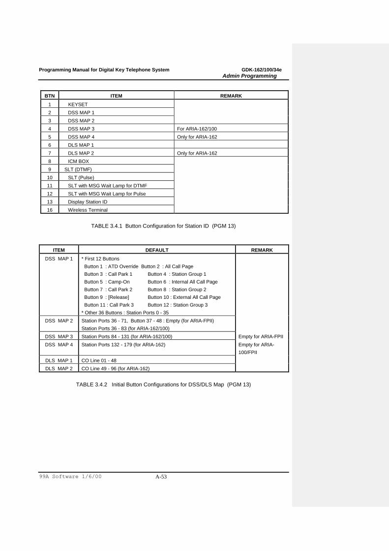
Programming Manual for Digital Key Telephone System GDK-162/100/34e
Admin Programming
99A Software 1/6/00 A-53
BTN ITEM REMARK
1 KEYSET
2 DSS MAP 1
3 DSS MAP 2
4 DSS MAP 3 For ARIA-162/100
5 DSS MAP 4 Only for ARIA-162
6 DLS MAP 1
7 DLS MAP 2 Only for ARIA-162
8 ICM BOX
9 SLT (DTMF)
10 SLT (Pulse)
11 SLT with MSG Wait Lamp for DTMF
12 SLT with MSG Wait Lamp for Pulse
13 Display Station ID
16 Wireless Terminal
TABLE 3.4.1 Button Configuration for Station ID (PGM 13)
ITEM DEFAULT REMARK
DSS MAP 1 * First 12 Buttons
Button 1 : ATD Override Button 2 : All Call Page
Button 3 : Call Park 1 Button 4 : Station Group 1
Button 5 : Camp-On Button 6 : Internal All Call Page
Button 7 : Call Park 2 Button 8 : Station Group 2
Button 9 : [Release] Button 10 : External All Call Page
Button 11 : Call Park 3 Button 12 : Station Group 3
* Other 36 Buttons : Station Ports 0 - 35
DSS MAP 2 Station Ports 36 - 71, Button 37 - 48 : Empty (for ARIA-FPII)
Station Ports 36 - 83 (for ARIA-162/100)
DSS MAP 3 Station Ports 84 - 131 (for ARIA-162/100) Empty for ARIA-FPII
DSS MAP 4 Station Ports 132 - 179 (for ARIA-162) Empty for ARIA-
100/FPII
DLS MAP 1 CO Line 01 - 48
DLS MAP 2 CO Line 49 - 96 (for ARIA-162)
TABLE 3.4.2 Initial Button Configurations for DSS/DLS Map (PGM 13)

Programming Manual for Digital Key Telephone System GDK-162/100/34e
Admin Programming
99A Software 1/6/00 A-54
3.5 STATION COS (PGM 14)
All stations COS for day and night operation 1 as default. For a particular call, the CO COS is
combined with station COS to determine restriction. Each station must be assigned a class of service
which governs that station's toll restriction for the day and night operation by entries in PGM 70. (Table
3.5.1 and Table 3.5.2)
STA COS 1 No restrictions are placed at the station for dialing.
STA COS 2 The assignments in the Allow/Deny Table A are monitored for allow and deny numbers.
STA COS 3 The assignments in the Allow/Deny Table B are monitored for allow and deny numbers.
STA COS 4 The assignments in both Allow/Deny Tables A & B are monitored for allow and deny numbers.
STA COS 5 The leading digit dialed can not be a long distance code. The dialed digits can be longer than 8
digits. There is no restriction for the number in Canned Toll Table.
STA COS 6 The leading digits can not be a Long Distance code. Only eight digits maximum can be dialed.
There is no restriction for the number in Canned Toll Table.
STA COS 7 Intercom and paging calls are allowed. No dialing allowed on CO lines. ICM boxes are assigned
with this COS.
TABLE 3.5.1 Station Class-Of-Service (PGM 14)
CO COS 1 CO COS 2 CO COS 3 CO COS 4 CO COS 5
STA
COS 1
No Restriction
Applied
No Restriction
Applied
No Restriction
Applied
Restricts Long
Distance code. Only
within 8 digits.
Possible to dial the
number in Canned
Toll Table.
No restriction
applied
STA
COS 2
Allow/Deny Table
A governs the
dialing
Allow/Deny Table
A governs the
dialing
No Restriction
Applied
Restricts Long
Distance code. Only
within 8 digits.
Possible to dial the
number in Canned
Toll Table.
No restriction
applied
STA
COS 3
Allow/Deny Table
B governs the
dialing
No Restriction
Applied
Allow/Deny Table
B governs the
dialing
Restricts Long
Distance code. Only
within 8 digits.
Possible to dial the
number in Canned
Toll Table.
No restriction
applied
STA
COS 4
Allow/Deny Table
A&B governs the
dialing
Allow/Deny Table
A governs the
dialing
Allow/Deny Table
B governs the
dialing
Restricts Long
Distance code. Only
within 8 digits.
Possible to dial the
number in Canned
Toll Table.
No restriction
applied

Programming Manual for Digital Key Telephone System GDK-162/100/34e
Admin Programming
99A Software 1/6/00 A-55
STA
COS 5
Restricts Long
Distance code.
Restricts Long
Distance code.
Restricts Long
Distance code.
Restricts Long
Distance code. Only
within 8 digits.
No restriction
applied
STA
COS 6
Restricts Long
Distance code.
Only within 8
digits. Possible to
dial the number in
Canned Toll
Table.
Restricts Long
Distance code.
Only within 8
digits. Possible to
dial the number in
Canned Toll
Table.
Restricts Long
Distance code.
Only within 8 digits.
Possible to dial the
number in Canned
Toll Table.
Restricts Long
Distance code. Only
within 8 digits.
Possible to dial the
number in Canned
Toll Table.
No restriction
applied
STA
COS 7
In-house dialing &
Emergency
entries only
In-house dialing &
Emergency
entries only
In-house dialing &
Emergency entries
only
In-house dialing &
Emergency entries
only
In-house dialing &
Emergency entries
only
TABLE 3.5.2 Toll Checking Table (PGM 14)
PROCEDURE
STATION COS
ENTER STA RANGE
(1) [TRANS/PGM] + 14.
100-110 STATION COS
DAY=1 NIGHT=1
(2) Enter station range (Ex. 100-110). Initially LED shows
associated item's status of the first station in range.
(3) To program, use the BTNs as Table 3.5.3. To change the COS
for day operation, press BTN 1 and dial COS (1 digit) and to
change the COS for night operation, press Flex BTN 2 and dial
COS (1 digit). Then changed COS will be displayed on LCD.
STATION COS
ENTER STA RANGE
(4) Press the [HOLD/SAVE] button for updating database
permanently.
STATION COS
ENTER STA RANGE
Press [] button instead of the [HOLD/SAVE] button, then
system goes to step (1) with no updating system memory.
BTN DEFAULT RANGE REMARK
1 1 1 - 7 Day Class-Of-Service
2 1 1 - 7 Night Class-Of-Service
TABLE 3.5.3 Button Configuration for Station COS (PGM 14)
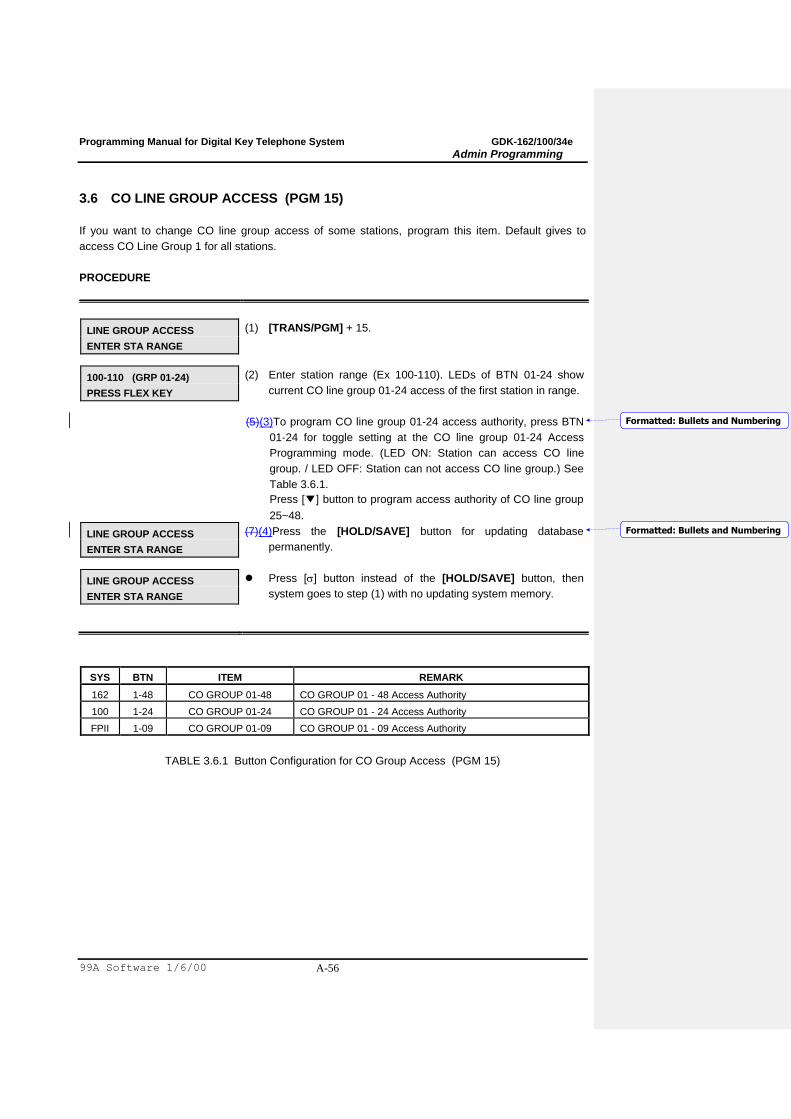
Programming Manual for Digital Key Telephone System GDK-162/100/34e
Admin Programming
99A Software 1/6/00 A-56
3.6 CO LINE GROUP ACCESS (PGM 15)
If you want to change CO line group access of some stations, program this item. Default gives to
access CO Line Group 1 for all stations.
PROCEDURE
LINE GROUP ACCESS
ENTER STA RANGE
(1) [TRANS/PGM] + 15.
100-110 (GRP 01-24)
PRESS FLEX KEY
(2) Enter station range (Ex 100-110). LEDs of BTN 01-24 show
current CO line group 01-24 access of the first station in range.
(5)(3)To program CO line group 01-24 access authority, press BTN
01-24 for toggle setting at the CO line group 01-24 Access
Programming mode. (LED ON: Station can access CO line
group. / LED OFF: Station can not access CO line group.) See
Table 3.6.1.
Press [▼] button to program access authority of CO line group
25~48.
LINE GROUP ACCESS
ENTER STA RANGE
(7)(4)Press the [HOLD/SAVE] button for updating database
permanently.
LINE GROUP ACCESS
ENTER STA RANGE
Press [] button instead of the [HOLD/SAVE] button, then
system goes to step (1) with no updating system memory.
SYS BTN ITEM REMARK
162 1-48 CO GROUP 01-48 CO GROUP 01 - 48 Access Authority
100 1-24 CO GROUP 01-24 CO GROUP 01 - 24 Access Authority
FPII 1-09 CO GROUP 01-09 CO GROUP 01 - 09 Access Authority
TABLE 3.6.1 Button Configuration for CO Group Access (PGM 15)
Formatted: Bullets and Numbering
Formatted: Bullets and Numbering
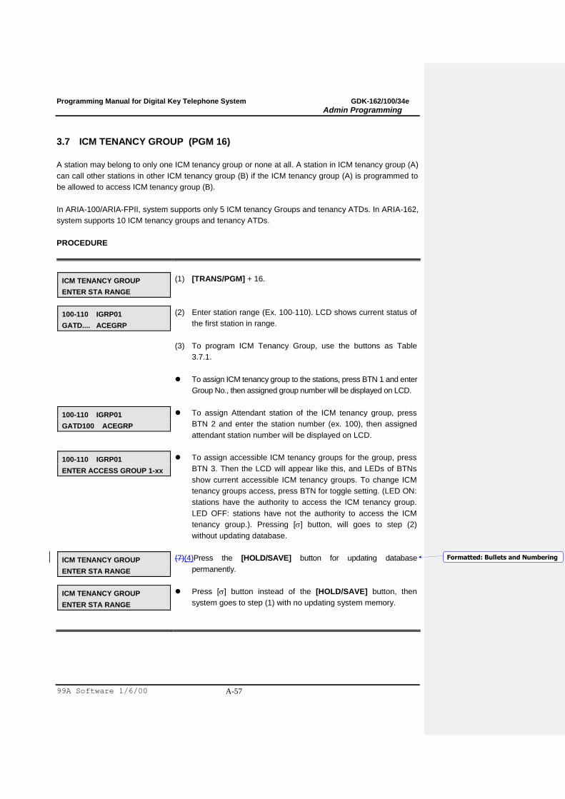
Programming Manual for Digital Key Telephone System GDK-162/100/34e
Admin Programming
99A Software 1/6/00 A-57
3.7 ICM TENANCY GROUP (PGM 16)
A station may belong to only one ICM tenancy group or none at all. A station in ICM tenancy group (A)
can call other stations in other ICM tenancy group (B) if the ICM tenancy group (A) is programmed to
be allowed to access ICM tenancy group (B).
In ARIA-100/ARIA-FPII, system supports only 5 ICM tenancy Groups and tenancy ATDs. In ARIA-162,
system supports 10 ICM tenancy groups and tenancy ATDs.
PROCEDURE
ICM TENANCY GROUP
ENTER STA RANGE
(1) [TRANS/PGM] + 16.
100-110 IGRP01
GATD.... ACEGRP
(2) Enter station range (Ex. 100-110). LCD shows current status of
the first station in range.
(3) To program ICM Tenancy Group, use the buttons as Table
3.7.1.
To assign ICM tenancy group to the stations, press BTN 1 and enter
Group No., then assigned group number will be displayed on LCD.
100-110 IGRP01
GATD100 ACEGRP
To assign Attendant station of the ICM tenancy group, press
BTN 2 and enter the station number (ex. 100), then assigned
attendant station number will be displayed on LCD.
100-110 IGRP01
ENTER ACCESS GROUP 1-xx
To assign accessible ICM tenancy groups for the group, press
BTN 3. Then the LCD will appear like this, and LEDs of BTNs
show current accessible ICM tenancy groups. To change ICM
tenancy groups access, press BTN for toggle setting. (LED ON:
stations have the authority to access the ICM tenancy group.
LED OFF: stations have not the authority to access the ICM
tenancy group.). Pressing [] button, will goes to step (2)
without updating database.
ICM TENANCY GROUP
ENTER STA RANGE
(7)(4)Press the [HOLD/SAVE] button for updating database
permanently.
ICM TENANCY GROUP
ENTER STA RANGE
Press [] button instead of the [HOLD/SAVE] button, then
system goes to step (1) with no updating system memory.
Formatted: Bullets and Numbering
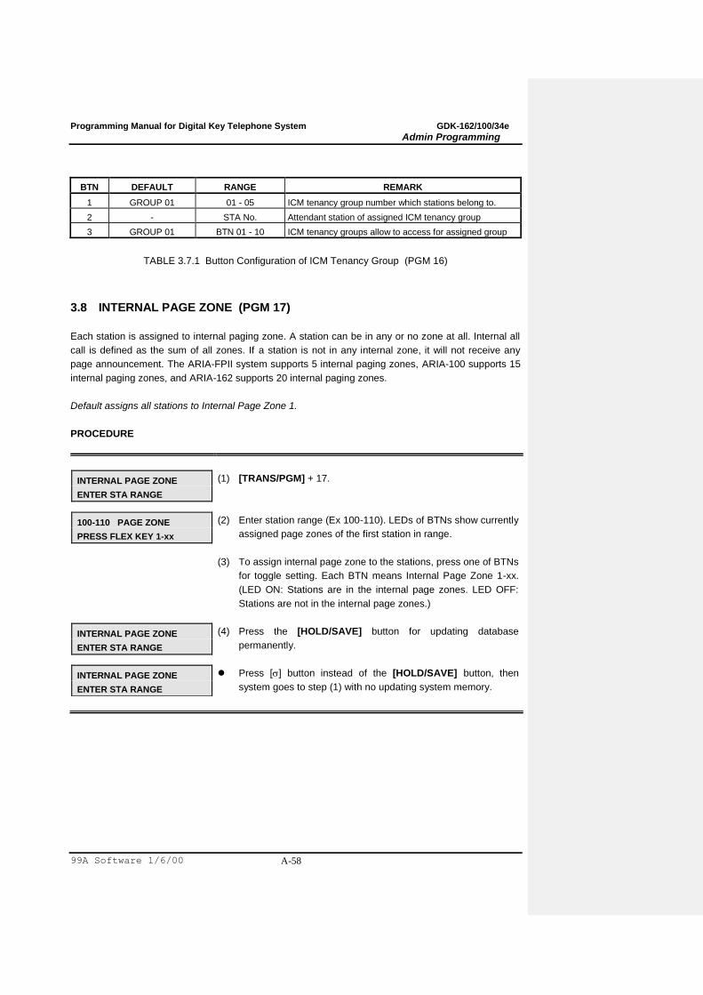
Programming Manual for Digital Key Telephone System GDK-162/100/34e
Admin Programming
99A Software 1/6/00 A-58
BTN DEFAULT RANGE REMARK
1 GROUP 01 01 - 05 ICM tenancy group number which stations belong to.
2 - STA No. Attendant station of assigned ICM tenancy group
3 GROUP 01 BTN 01 - 10 ICM tenancy groups allow to access for assigned group
TABLE 3.7.1 Button Configuration of ICM Tenancy Group (PGM 16)
3.8 INTERNAL PAGE ZONE (PGM 17)
Each station is assigned to internal paging zone. A station can be in any or no zone at all. Internal all
call is defined as the sum of all zones. If a station is not in any internal zone, it will not receive any
page announcement. The ARIA-FPII system supports 5 internal paging zones, ARIA-100 supports 15
internal paging zones, and ARIA-162 supports 20 internal paging zones.
Default assigns all stations to Internal Page Zone 1.
PROCEDURE
INTERNAL PAGE ZONE
ENTER STA RANGE
(1) [TRANS/PGM] + 17.
100-110 PAGE ZONE
PRESS FLEX KEY 1-xx
(2) Enter station range (Ex 100-110). LEDs of BTNs show currently
assigned page zones of the first station in range.
(3) To assign internal page zone to the stations, press one of BTNs
for toggle setting. Each BTN means Internal Page Zone 1-xx.
(LED ON: Stations are in the internal page zones. LED OFF:
Stations are not in the internal page zones.)
INTERNAL PAGE ZONE
ENTER STA RANGE
(4) Press the [HOLD/SAVE] button for updating database
permanently.
INTERNAL PAGE ZONE
ENTER STA RANGE
Press [] button instead of the [HOLD/SAVE] button, then
system goes to step (1) with no updating system memory.

Programming Manual for Digital Key Telephone System GDK-162/100/34e
Admin Programming
99A Software 1/6/00 A-59
3.9 PRESET CALL FORWARD (PGM 18)
A station can be programmed so that incoming CO lines can be forwarded to a presetting station if the
first station does not answer after Preset Call Forward timer. No station is assigned as default.
PROCEDURE
CALL FWD PRESET
ENTER STA NUMBER
(1) [TRANS/PGM] + 18.
CALL FWD PRESET
FROM 101 TO ....
(2) Enter the station number want to forward (Ex.101). LCD shows
current status of the station.
CALL FWD PRESET
FROM 101 TO 102
(3) Enter the preset station number which the first station forward
to. (Ex.102)
CALL FWD PRESET
FROM 101 TO ....
To clear the Preset Call Forward station, press the [SPEED]
button.
CALL FWD PRESET
ENTER STA NUMBER
(7)(4)Press the [HOLD/SAVE] button for updating database
permanently.
CALL FWD PRESET
ENTER STA NUMBER
Press [] button instead of the [HOLD/SAVE] button, then
system goes to step (1) with no updating system memory.
Formatted: Bullets and Numbering
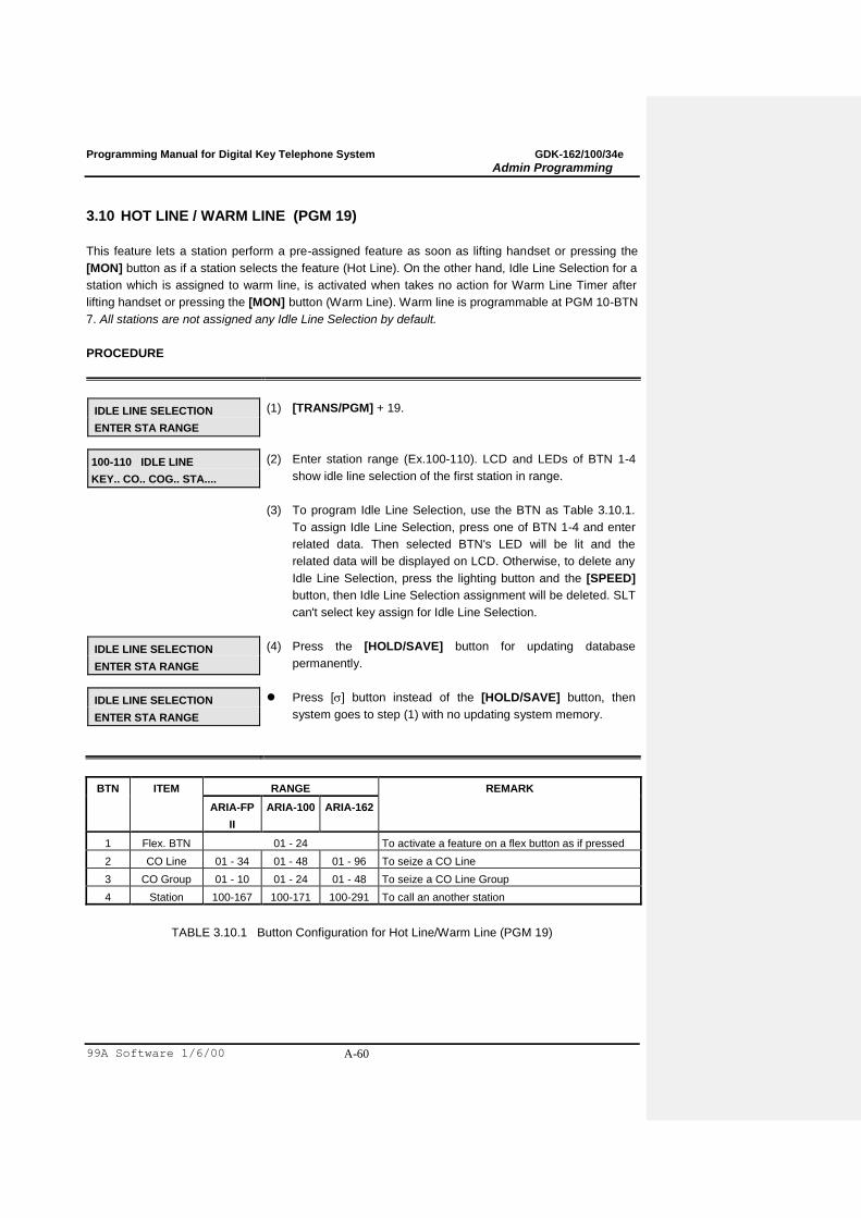
Programming Manual for Digital Key Telephone System GDK-162/100/34e
Admin Programming
99A Software 1/6/00 A-60
3.10 HOT LINE / WARM LINE (PGM 19)
This feature lets a station perform a pre-assigned feature as soon as lifting handset or pressing the
[MON] button as if a station selects the feature (Hot Line). On the other hand, Idle Line Selection for a
station which is assigned to warm line, is activated when takes no action for Warm Line Timer after
lifting handset or pressing the [MON] button (Warm Line). Warm line is programmable at PGM 10-BTN
7. All stations are not assigned any Idle Line Selection by default.
PROCEDURE
IDLE LINE SELECTION
ENTER STA RANGE
(1) [TRANS/PGM] + 19.
100-110 IDLE LINE
KEY.. CO.. COG.. STA....
(2) Enter station range (Ex.100-110). LCD and LEDs of BTN 1-4
show idle line selection of the first station in range.
(3) To program Idle Line Selection, use the BTN as Table 3.10.1.
To assign Idle Line Selection, press one of BTN 1-4 and enter
related data. Then selected BTN's LED will be lit and the
related data will be displayed on LCD. Otherwise, to delete any
Idle Line Selection, press the lighting button and the [SPEED]
button, then Idle Line Selection assignment will be deleted. SLT
can't select key assign for Idle Line Selection.
IDLE LINE SELECTION
ENTER STA RANGE
(4) Press the [HOLD/SAVE] button for updating database
permanently.
IDLE LINE SELECTION
ENTER STA RANGE
Press [] button instead of the [HOLD/SAVE] button, then
system goes to step (1) with no updating system memory.
BTN ITEM RANGE REMARK
ARIA-FP
II
ARIA-100 ARIA-162
1 Flex. BTN 01 - 24 To activate a feature on a flex button as if pressed
2 CO Line 01 - 34 01 - 48 01 - 96 To seize a CO Line
3 CO Group 01 - 10 01 - 24 01 - 48 To seize a CO Line Group
4 Station 100-167 100-171 100-291 To call an another station
TABLE 3.10.1 Button Configuration for Hot Line/Warm Line (PGM 19)
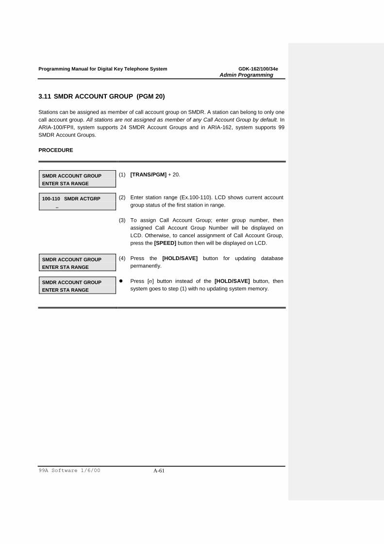
Programming Manual for Digital Key Telephone System GDK-162/100/34e
Admin Programming
99A Software 1/6/00 A-61
3.11 SMDR ACCOUNT GROUP (PGM 20)
Stations can be assigned as member of call account group on SMDR. A station can belong to only one
call account group. All stations are not assigned as member of any Call Account Group by default. In
ARIA-100/FPII, system supports 24 SMDR Account Groups and in ARIA-162, system supports 99
SMDR Account Groups.
PROCEDURE
SMDR ACCOUNT GROUP
ENTER STA RANGE
(1) [TRANS/PGM] + 20.
100-110 SMDR ACTGRP
..
(2) Enter station range (Ex.100-110). LCD shows current account
group status of the first station in range.
(3) To assign Call Account Group; enter group number, then
assigned Call Account Group Number will be displayed on
LCD. Otherwise, to cancel assignment of Call Account Group,
press the [SPEED] button then will be displayed on LCD.
SMDR ACCOUNT GROUP
ENTER STA RANGE
(4) Press the [HOLD/SAVE] button for updating database
permanently.
SMDR ACCOUNT GROUP
ENTER STA RANGE
Press [] button instead of the [HOLD/SAVE] button, then
system goes to step (1) with no updating system memory.
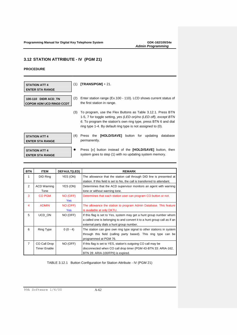
Programming Manual for Digital Key Telephone System GDK-162/100/34e
Admin Programming
99A Software 1/6/00 A-62
3.12 STATION ATTRIBUTE - IV (PGM 21)
PROCEDURE
STATION ATT 4
ENTER STA RANGE
(1) [TRANS/PGM] + 21.
100-110 DIDR ACD_TN
COPGM ADM UCD RING0 CCDT
(2) Enter station range (Ex.100 - 110). LCD shows current status of
the first station in range.
(3) To program, use the Flex Buttons as Table 3.12.1. Press BTN
1-5, 7 for toggle setting, yes (LED on)/no (LED off), except BTN
6. To program the station's own ring type, press BTN 6 and dial
ring type 1-4. By default ring type is not assigned to (0).
STATION ATT 4
ENTER STA RANGE
(4) Press the [HOLD/SAVE] button for updating database
permanently.
STATION ATT 4
ENTER STA RANGE
Press [] button instead of the [HOLD/SAVE] button, then
system goes to step (1) with no updating system memory.
BTN ITEM DEFAULT(LED) REMARK
1 DID Ring YES (ON) The allowance that the station call through DID line is presented at
station. If this field is set to No, the call is transferred to attendant.
2 ACD Warning
Tone
YES (ON) Determines that the ACD supervisor monitors an agent with warning
tone or without warning tone.
3 CO PGM NO (OFF)
Yes
Determines that each station user can program CO button or not.
4 ADMIN NO (OFF)
Yes
The allowance the station to program Admin Database. This feature
is available at only DKTU.
5 UCD_ON NO (OFF) If this flag is set to Yes, system may get a hunt group number whom
a called one is belonging to and convert it to a hunt group call as if an
external party dials a hunt group number.
6 Ring Type 0 (0 - 4) The station can give own ring type signal to other stations in system
through this field (calling party based). This ring type can be
programmed at PGM 76.
7 CO Call Drop
Timer Enable
NO (OFF) If this flag is set to YES, station's outgoing CO call may be
disconnected when CO call drop timer (PGM 43-BTN 33: ARIA-162,
BTN 28: ARIA-100/FPII) is expired.
TABLE 3.12.1 Button Configuration for Station Attribute - IV (PGM 21)
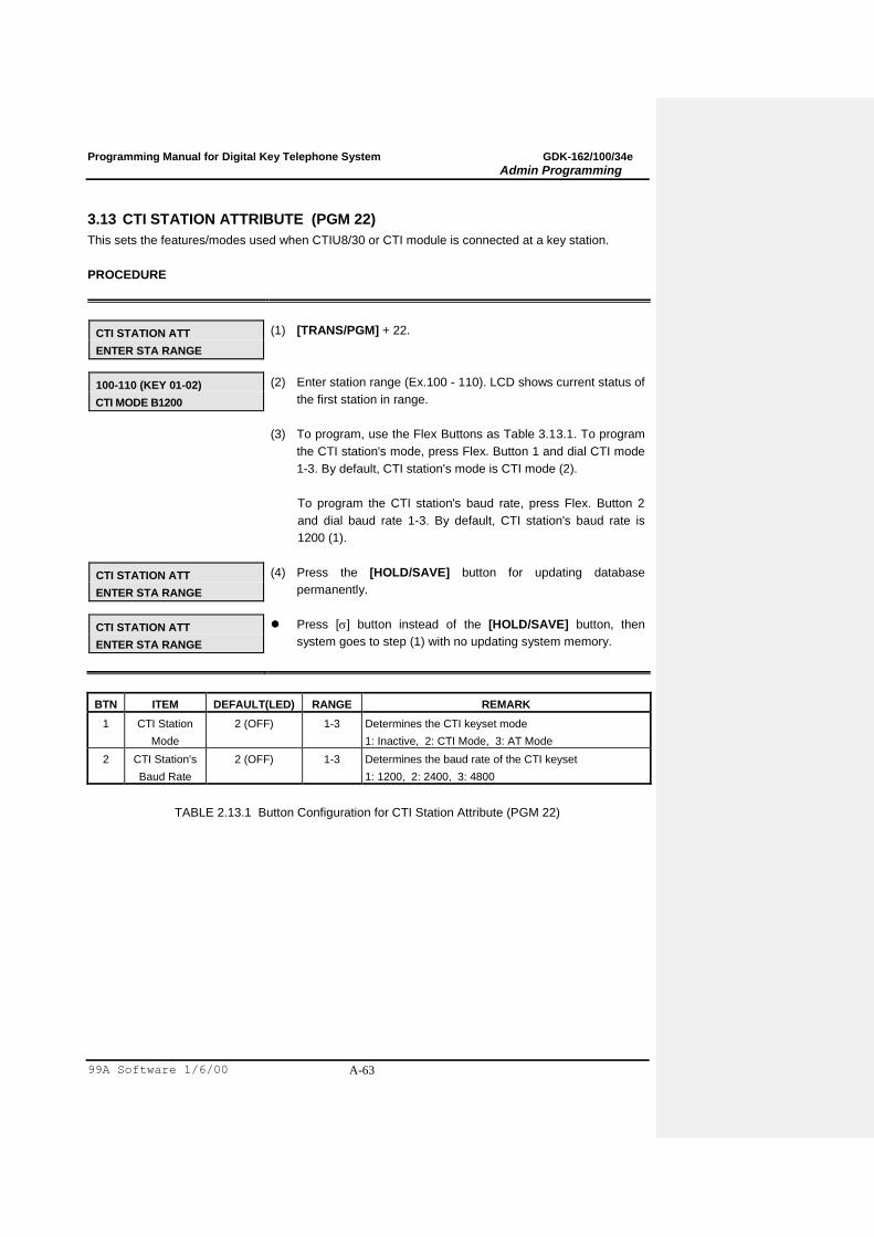
Programming Manual for Digital Key Telephone System GDK-162/100/34e
Admin Programming
99A Software 1/6/00 A-63
3.13 CTI STATION ATTRIBUTE (PGM 22)
This sets the features/modes used when CTIU8/30 or CTI module is connected at a key station.
PROCEDURE
CTI STATION ATT
ENTER STA RANGE
(1) [TRANS/PGM] + 22.
100-110 (KEY 01-02)
CTI MODE B1200
(2) Enter station range (Ex.100 - 110). LCD shows current status of
the first station in range.
(3) To program, use the Flex Buttons as Table 3.13.1. To program
the CTI station's mode, press Flex. Button 1 and dial CTI mode
1-3. By default, CTI station's mode is CTI mode (2).
To program the CTI station's baud rate, press Flex. Button 2
and dial baud rate 1-3. By default, CTI station's baud rate is
1200 (1).
CTI STATION ATT
ENTER STA RANGE
(4) Press the [HOLD/SAVE] button for updating database
permanently.
CTI STATION ATT
ENTER STA RANGE
Press [] button instead of the [HOLD/SAVE] button, then
system goes to step (1) with no updating system memory.
BTN ITEM DEFAULT(LED) RANGE REMARK
1 CTI Station
Mode
2 (OFF) 1-3 Determines the CTI keyset mode
1: Inactive, 2: CTI Mode, 3: AT Mode
2 CTI Station's
Baud Rate
2 (OFF) 1-3 Determines the baud rate of the CTI keyset
1: 1200, 2: 2400, 3: 4800
TABLE 2.13.1 Button Configuration for CTI Station Attribute (PGM 22)
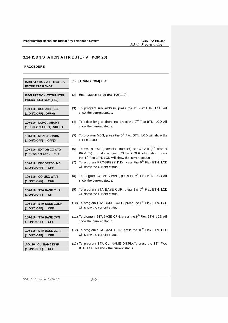
Programming Manual for Digital Key Telephone System GDK-162/100/34e
Admin Programming
99A Software 1/6/00 A-64
3.14 ISDN STATION ATTRIBUTE - V (PGM 23)
PROCEDURE
ISDN STATION ATTRIBUTES
ENTER STA RANGE
(1) [TRANS/PGM] + 23.
ISDN STATION ATTRIBUTES
PRESS FLEX KEY (1-10)
(2) Enter station range (Ex. 100-110).
100-110 : SUB ADDRESS
(1:ON/0:OFF) : OFF(0)
(3) To program sub address, press the 1st Flex BTN. LCD will
show the current status.
100-110 : LONG / SHORT
(1:LONG/0:SHORT): SHORT
(4) To select long or short line, press the 2nd
Flex BTN. LCD will
show the current status.
100-110 : MSN FOR ISDN
(1:ON/0:OFF) : OFF(0)
(5) To program MSN, press the 3rd
Flex BTN. LCD will show the
current status.
100-110 : EXT OR CO ATD
(1:EXT/0:CO ATD) : EXT
(6) To select EXT (extension number) or CO ATD(3rd
field of
PGM 08) to make outgoing CLI or COLP information, press
the 4th Flex BTN. LCD will show the current status.
100-110 : PROGRESS IND
(1:ON/0:OFF) : OFF
(7) To program PROGRESS IND, press the 5th Flex BTN. LCD
will show the current status.
100-110 : CO MSG WAIT
(1:ON/0:OFF) : OFF
(8) To program CO MSG WAIT, press the 6th Flex BTN. LCD will
show the current status.
100-110 : STA BASE CLIP
(1:ON/0:OFF) : ON
(9) To program STA BASE CLIP, press the 7th Flex BTN. LCD
will show the current status.
100-110 : STA BASE COLP
(1:ON/0:OFF) : OFF
(10) To program STA BASE COLP, press the 8th Flex BTN. LCD
will show the current status.
100-110 : STA BASE CPN
(1:ON/0:OFF) : OFF
(11) To program STA BASE CPN, press the 9th Flex BTN. LCD will
show the current status.
100-110 : STA BASE CLIR
(1:ON/0:OFF) : OFF
(12) To program STA BASE CLIR, press the 10th Flex BTN. LCD
will show the current status.
100-110 : CLI NAME DISP
(1:ON/0:OFF) : OFF
(13) To program STA CLI NAME DISPLAY, press the 11th Flex.
BTN. LCD will show the current status.
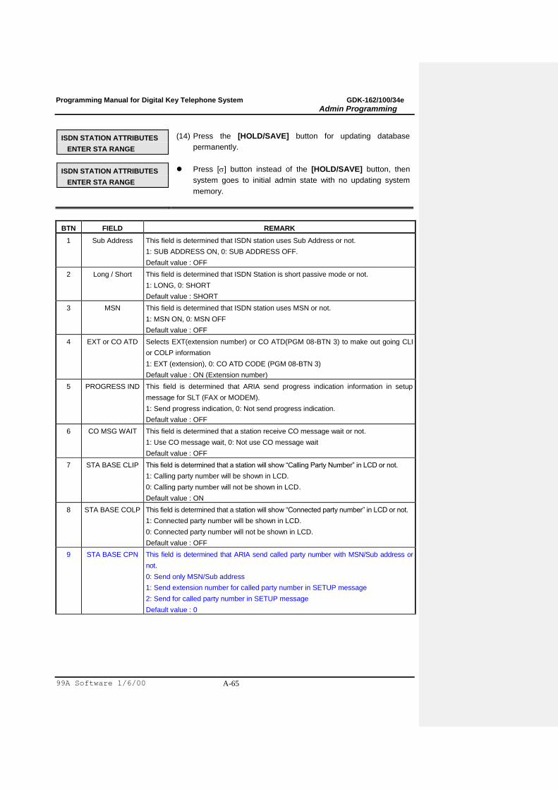
Programming Manual for Digital Key Telephone System GDK-162/100/34e
Admin Programming
99A Software 1/6/00 A-65
ISDN STATION ATTRIBUTES
ENTER STA RANGE
(14) Press the [HOLD/SAVE] button for updating database
permanently.
ISDN STATION ATTRIBUTES
ENTER STA RANGE
Press [] button instead of the [HOLD/SAVE] button, then
system goes to initial admin state with no updating system
memory.
BTN FIELD REMARK
1 Sub Address This field is determined that ISDN station uses Sub Address or not.
1: SUB ADDRESS ON, 0: SUB ADDRESS OFF.
Default value : OFF
2 Long / Short This field is determined that ISDN Station is short passive mode or not.
1: LONG, 0: SHORT
Default value : SHORT
3 MSN This field is determined that ISDN station uses MSN or not.
1: MSN ON, 0: MSN OFF
Default value : OFF
4 EXT or CO ATD Selects EXT(extension number) or CO ATD(PGM 08-BTN 3) to make out going CLI
or COLP information
1: EXT (extension), 0: CO ATD CODE (PGM 08-BTN 3)
Default value : ON (Extension number)
5 PROGRESS IND This field is determined that ARIA send progress indication information in setup
message for SLT (FAX or MODEM).
1: Send progress indication, 0: Not send progress indication.
Default value : OFF
6 CO MSG WAIT This field is determined that a station receive CO message wait or not.
1: Use CO message wait, 0: Not use CO message wait
Default value : OFF
7 STA BASE CLIP This field is determined that a station will show “Calling Party Number” in LCD or not.
1: Calling party number will be shown in LCD.
0: Calling party number will not be shown in LCD.
Default value : ON
8 STA BASE COLP This field is determined that a station will show “Connected party number” in LCD or not.
1: Connected party number will be shown in LCD.
0: Connected party number will not be shown in LCD.
Default value : OFF
9 STA BASE CPN This field is determined that ARIA send called party number with MSN/Sub address or
not.
0: Send only MSN/Sub address
1: Send extension number for called party number in SETUP message
2: Send for called party number in SETUP message
Default value : 0
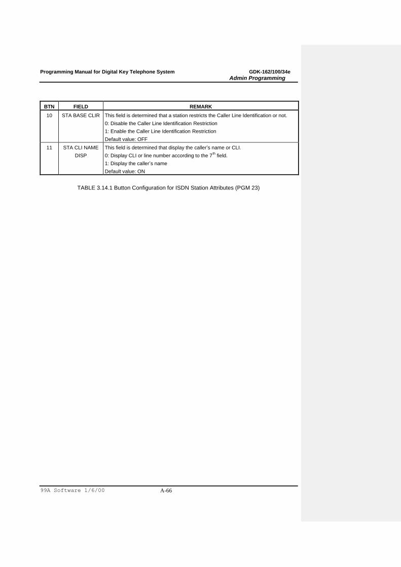
Programming Manual for Digital Key Telephone System GDK-162/100/34e
Admin Programming
99A Software 1/6/00 A-66
BTN FIELD REMARK
10 STA BASE CLIR This field is determined that a station restricts the Caller Line Identification or not.
0: Disable the Caller Line Identification Restriction
1: Enable the Caller Line Identification Restriction
Default value: OFF
11 STA CLI NAME
DISP
This field is determined that display the caller‟s name or CLI.
0: Display CLI or line number according to the 7th field.
1: Display the caller‟s name
Default value: ON
TABLE 3.14.1 Button Configuration for ISDN Station Attributes (PGM 23)
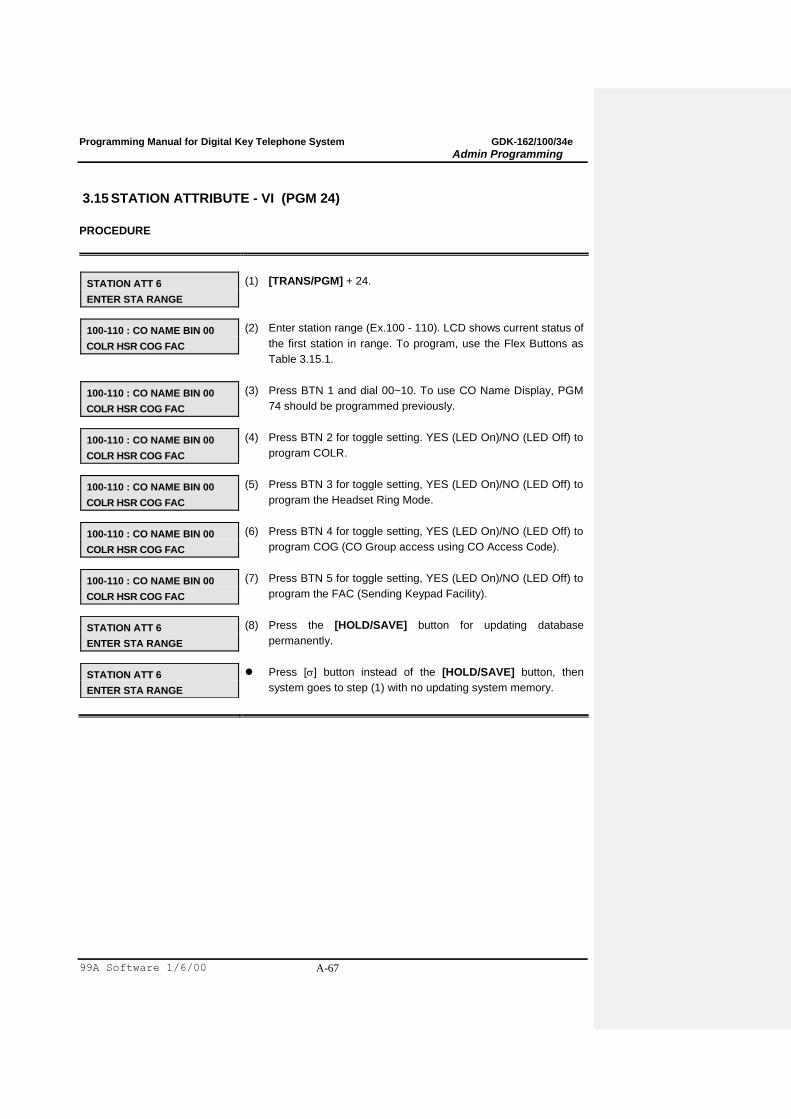
Programming Manual for Digital Key Telephone System GDK-162/100/34e
Admin Programming
99A Software 1/6/00 A-67
3.15 STATION ATTRIBUTE - VI (PGM 24)
PROCEDURE
STATION ATT 6
ENTER STA RANGE
(1) [TRANS/PGM] + 24.
100-110 : CO NAME BIN 00
COLR HSR COG FAC
(2) Enter station range (Ex.100 - 110). LCD shows current status of
the first station in range. To program, use the Flex Buttons as
Table 3.15.1.
100-110 : CO NAME BIN 00
COLR HSR COG FAC
(3) Press BTN 1 and dial 00~10. To use CO Name Display, PGM
74 should be programmed previously.
100-110 : CO NAME BIN 00
COLR HSR COG FAC
(4) Press BTN 2 for toggle setting. YES (LED On)/NO (LED Off) to
program COLR.
100-110 : CO NAME BIN 00
COLR HSR COG FAC
(5) Press BTN 3 for toggle setting, YES (LED On)/NO (LED Off) to
program the Headset Ring Mode.
100-110 : CO NAME BIN 00
COLR HSR COG FAC
(6) Press BTN 4 for toggle setting, YES (LED On)/NO (LED Off) to
program COG (CO Group access using CO Access Code).
100-110 : CO NAME BIN 00
COLR HSR COG FAC
(7) Press BTN 5 for toggle setting, YES (LED On)/NO (LED Off) to
program the FAC (Sending Keypad Facility).
STATION ATT 6
ENTER STA RANGE
(8) Press the [HOLD/SAVE] button for updating database
permanently.
STATION ATT 6
ENTER STA RANGE
Press [] button instead of the [HOLD/SAVE] button, then
system goes to step (1) with no updating system memory.
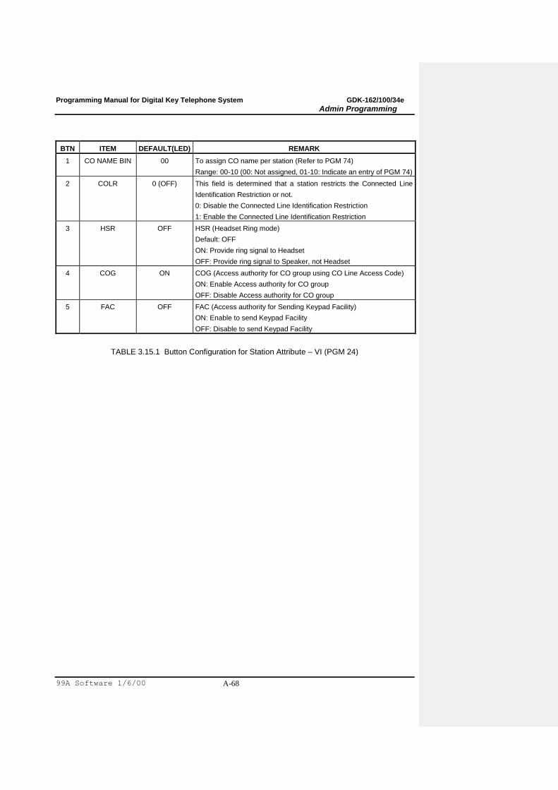
Programming Manual for Digital Key Telephone System GDK-162/100/34e
Admin Programming
99A Software 1/6/00 A-68
BTN ITEM DEFAULT(LED) REMARK
1 CO NAME BIN 00 To assign CO name per station (Refer to PGM 74)
Range: 00-10 (00: Not assigned, 01-10: Indicate an entry of PGM 74)
2 COLR 0 (OFF) This field is determined that a station restricts the Connected Line
Identification Restriction or not.
0: Disable the Connected Line Identification Restriction
1: Enable the Connected Line Identification Restriction
3 HSR
OFF HSR (Headset Ring mode)
Default: OFF
ON: Provide ring signal to Headset
OFF: Provide ring signal to Speaker, not Headset
4 COG ON COG (Access authority for CO group using CO Line Access Code)
ON: Enable Access authority for CO group
OFF: Disable Access authority for CO group
5 FAC OFF FAC (Access authority for Sending Keypad Facility)
ON: Enable to send Keypad Facility
OFF: Disable to send Keypad Facility
TABLE 3.15.1 Button Configuration for Station Attribute – VI (PGM 24)
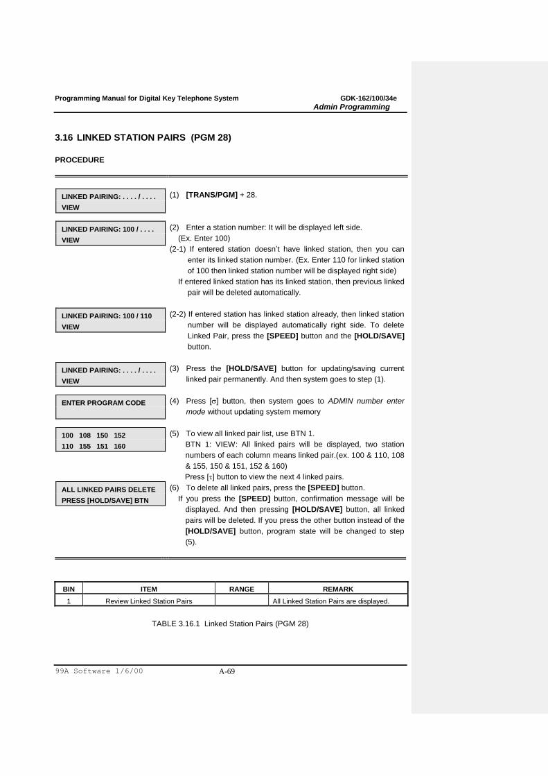
Programming Manual for Digital Key Telephone System GDK-162/100/34e
Admin Programming
99A Software 1/6/00 A-69
3.16 LINKED STATION PAIRS (PGM 28)
PROCEDURE
LINKED PAIRING: . . . . / . . . .
VIEW
(1) [TRANS/PGM] + 28.
LINKED PAIRING: 100 / . . . .
VIEW
(2) Enter a station number: It will be displayed left side.
(Ex. Enter 100)
(2-1) If entered station doesn‟t have linked station, then you can
enter its linked station number. (Ex. Enter 110 for linked station
of 100 then linked station number will be displayed right side)
If entered linked station has its linked station, then previous linked
pair will be deleted automatically.
LINKED PAIRING: 100 / 110
VIEW
(2-2) If entered station has linked station already, then linked station
number will be displayed automatically right side. To delete
Linked Pair, press the [SPEED] button and the [HOLD/SAVE]
button.
LINKED PAIRING: . . . . / . . . .
VIEW
(3) Press the [HOLD/SAVE] button for updating/saving current
linked pair permanently. And then system goes to step (1).
ENTER PROGRAM CODE
(4) Press [] button, then system goes to ADMIN number enter
mode without updating system memory
100 108 150 152
110 155 151 160
(5) To view all linked pair list, use BTN 1.
BTN 1: VIEW: All linked pairs will be displayed, two station
numbers of each column means linked pair.(ex. 100 & 110, 108
& 155, 150 & 151, 152 & 160)
Press [] button to view the next 4 linked pairs.
ALL LINKED PAIRS DELETE
PRESS [HOLD/SAVE] BTN
(6) To delete all linked pairs, press the [SPEED] button.
If you press the [SPEED] button, confirmation message will be
displayed. And then pressing [HOLD/SAVE] button, all linked
pairs will be deleted. If you press the other button instead of the
[HOLD/SAVE] button, program state will be changed to step
(5).
BIN ITEM RANGE REMARK
1 Review Linked Station Pairs All Linked Station Pairs are displayed.
TABLE 3.16.1 Linked Station Pairs (PGM 28)

Programming Manual for Digital Key Telephone System GDK-162/100/34e
Admin Programming
99A Software 1/6/00 A-70
3.17 FLEX BUTTON ASSIGNMENT (PGM 29)
Each Flex. Button of key station can be assigned identified as one of the followings.
No. Type RANGE REMARK
FP II 100 162
1 User Button - User can program by button programming procedure.
2 {CO xx} Button 01 – 34 01 – 48 01 – 96 CO Line
3 {CO Grp xx} 01 – 09 01 – 24 01 – 48 CO Group
4 {LOOP} -
5 {STAxxxx} 100 –
133
100 –
171
100-291 Station No.
6 Sta PGM Button Station Programming Code
7 {SPDxxx} 00 –19 /
200-399
00 –19 /
200-399
00 – 19/
200-999
Speed Bin
TABLE 3.17.1 Button Type for Flexible Button Assignment (PGM 29)
PROCEDURE
FLEX BUTTONS
ENTER STA RANGE
(1) [TRANS/PGM] + 29.
(KEY 01-24)
PRESS FLEX KEY
(2) Enter station range (Ex.100 –110).
(KEY 25-48)
PRESS FLEX KEY
In this status, if you press [] button, then you go to the BTN
25-48 programming mode.
(KEY 01-24)
BUTTON 01 = CO 01
(5)(3)To program Flex. Button, press the BTN which you want to
program (Ex. BTN 1). The LCD will display current BTN
assignment of the first station in range, and LED of the BTN (ex
BTN 1) will be lit. (See Table 3.13.3). Enter data, then entered
data will be displayed on LCD. (See Table 3.13.3)
FLEX BUTTONS
ENTER STA RANGE
(6)(4)Press the [HOLD/SAVE] button for updating database
permanently.
FLEX BUTTONS
ENTER STA RANGE
Press [] button instead of the [HOLD/SAVE] button, then
system goes to step (1) with no updating system memory.
Formatted: Bullets and Numbering
Formatted: Bullets and Numbering

Programming Manual for Digital Key Telephone System GDK-162/100/34e
Admin Programming
99A Software 1/6/00 A-71
BTN 8 Button (Analog) 12 Button (Analog/Digital) 24 Button (Analog/Digital)
1 {LOOP} {CO 1} {CO 1}
2 [SPEED] {CO 2} {CO 2}
3 {CO 1} {CO 3} {CO 3}
4 [FLASH] {CO 4} {CO 4}
5 {CO 2} {CO 5} {CO 5}
6 [MON] {CO 6} {CO 6}
7 {CO 7} {CO 7}
8 {CO 8} {CO 8}
9 {CO 9} {CO 9}
10 {CO 10} {CO 10}
11 {CO 11} {CO 11}
12 {LOOP} {LOOP}
13 – 24 - Empty
TABLE 3.17.2 Initial Button Configuration (PGM 29)
BTN TYPE DATA
Button 01 – 24 1 – 24 1 : User Button
2 : {Coxx}
-
CO Line
Button 25 – 48 1 – 24 3 : {COGRPxx}
4 : {LOOP}
5 : {STAxxx}
6 : STA PGM Button
7 : {SPDxxx}
CO Group
-
Station No
Station Programming Code *
Speed Bin No.
*) List of Station Programming Code is at Table 1.4.2 (P.7).
TABLE 3.17.3 Button Configuration for Flexible Button Assignments (PGM 29)
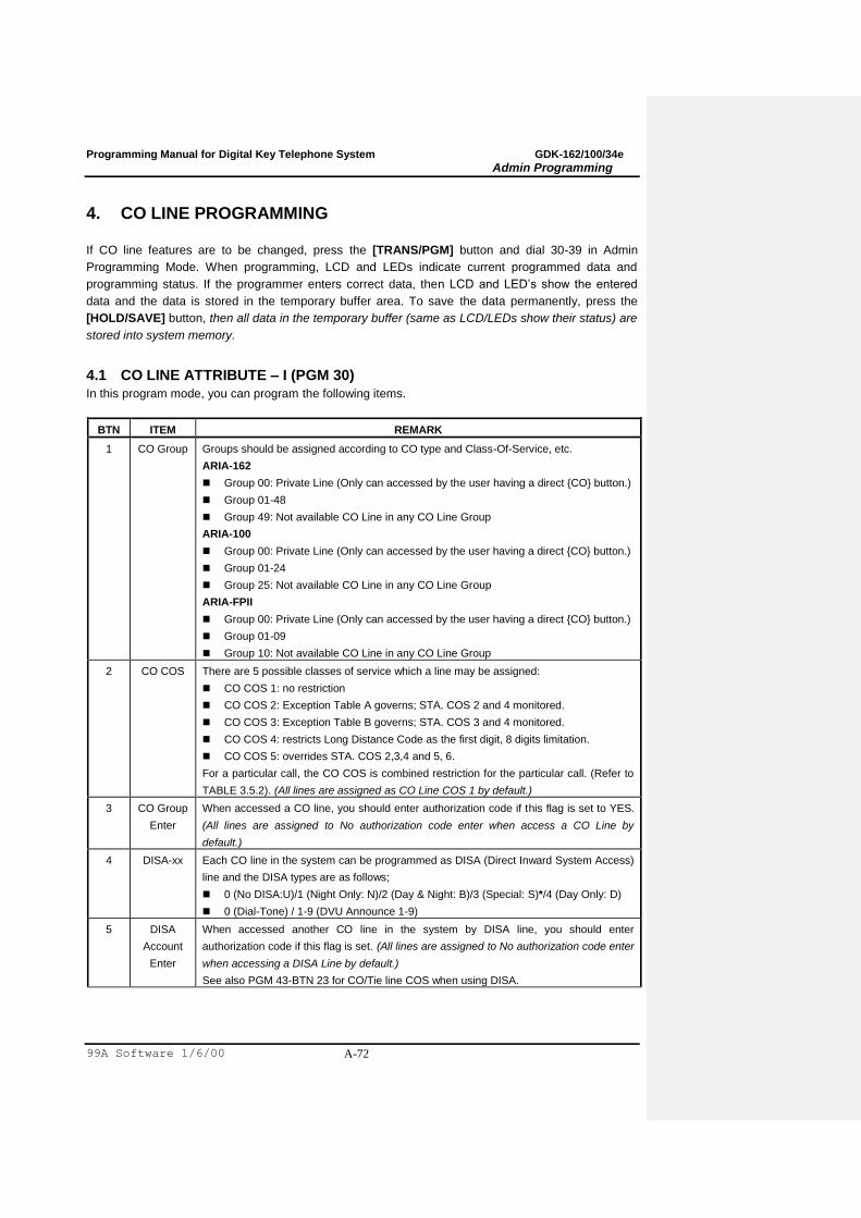
Programming Manual for Digital Key Telephone System GDK-162/100/34e
Admin Programming
99A Software 1/6/00 A-72
4. CO LINE PROGRAMMING
If CO line features are to be changed, press the [TRANS/PGM] button and dial 30-39 in Admin
Programming Mode. When programming, LCD and LEDs indicate current programmed data and
programming status. If the programmer enters correct data, then LCD and LED‟s show the entered
data and the data is stored in the temporary buffer area. To save the data permanently, press the
[HOLD/SAVE] button, then all data in the temporary buffer (same as LCD/LEDs show their status) are
stored into system memory.
4.1 CO LINE ATTRIBUTE – I (PGM 30)
In this program mode, you can program the following items.
BTN ITEM REMARK
1 CO Group Groups should be assigned according to CO type and Class-Of-Service, etc.
ARIA-162
Group 00: Private Line (Only can accessed by the user having a direct {CO} button.)
Group 01-48
Group 49: Not available CO Line in any CO Line Group
ARIA-100
Group 00: Private Line (Only can accessed by the user having a direct {CO} button.)
Group 01-24
Group 25: Not available CO Line in any CO Line Group
ARIA-FPII
Group 00: Private Line (Only can accessed by the user having a direct {CO} button.)
Group 01-09
Group 10: Not available CO Line in any CO Line Group
2 CO COS There are 5 possible classes of service which a line may be assigned:
CO COS 1: no restriction
CO COS 2: Exception Table A governs; STA. COS 2 and 4 monitored.
CO COS 3: Exception Table B governs; STA. COS 3 and 4 monitored.
CO COS 4: restricts Long Distance Code as the first digit, 8 digits limitation.
CO COS 5: overrides STA. COS 2,3,4 and 5, 6.
For a particular call, the CO COS is combined restriction for the particular call. (Refer to
TABLE 3.5.2). (All lines are assigned as CO Line COS 1 by default.)
3 CO Group
Enter
When accessed a CO line, you should enter authorization code if this flag is set to YES.
(All lines are assigned to No authorization code enter when access a CO Line by
default.)
4 DISA-xx Each CO line in the system can be programmed as DISA (Direct Inward System Access)
line and the DISA types are as follows;
0 (No DISA:U)/1 (Night Only: N)/2 (Day & Night: B)/3 (Special: S)*/4 (Day Only: D)
0 (Dial-Tone) / 1-9 (DVU Announce 1-9)
5 DISA
Account
Enter
When accessed another CO line in the system by DISA line, you should enter
authorization code if this flag is set. (All lines are assigned to No authorization code enter
when accessing a DISA Line by default.)
See also PGM 43-BTN 23 for CO/Tie line COS when using DISA.
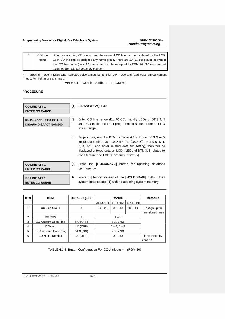
Programming Manual for Digital Key Telephone System GDK-162/100/34e
Admin Programming
99A Software 1/6/00 A-73
6 CO Line
Name
When an incoming CO line occurs, the name of CO line can be displayed on the LCD.
Each CO line can be assigned any name group. There are 10 (01-10) groups in system
and CO line name (max. 12 characters) can be assigned by PGM 74. (All lines are not
assigned with CO line name by default.)
*) In “Special” mode in DISA type; selected voice announcement for Day mode and fixed voice announcement
no.2 for Night mode are heard.
TABLE 4.1.1 CO Line Attribute – I (PGM 30)
PROCEDURE
CO LINE ATT 1
ENTER CO RANGE
(1) [TRANS/PGM] + 30.
01-05 GRP01 COS1 COACT
DISA:U0 DISAACT NAME00
(2) Enter CO line range (Ex. 01-05). Initially LEDs of BTN 3, 5
and LCD indicate current programming status of the first CO
line in range.
(3) To program, use the BTN as Table 4.1.2. Press BTN 3 or 5
for toggle setting, yes (LED on) /no (LED off). Press BTN 1,
2, 4, or 6 and enter related data for setting, then will be
displayed entered data on LCD. (LEDs of BTN 3, 5 related to
each feature and LCD show current status)
CO LINE ATT 1
ENTER CO RANGE
(4) Press the [HOLD/SAVE] button for updating database
permanently.
CO LINE ATT 1
ENTER CO RANGE
Press [] button instead of the [HOLD/SAVE] button, then
system goes to step (1) with no updating system memory.
BTN ITEM DEFAULT (LED) RANGE REMARK
ARIA-100 ARIA-162 ARIA-FPII
1 CO Line Group 1 00 – 25 00 – 49 00 – 10 Last group for
unassigned lines
2 CO COS 1 1 – 5
3 CO Account Code Flag NO (OFF) YES / NO
4 DISA-xx U0 (OFF) 0 – 4, 0 – 9
5 DISA Account Code Flag YES (ON) YES / NO
6 CO Name Number 00 (OFF) 00 – 10 It is assigned by
PGM 74.
TABLE 4.1.2 Button Configuration For CO Attribute – I (PGM 30)

Programming Manual for Digital Key Telephone System GDK-162/100/34e
Admin Programming
99A Software 1/6/00 A-74
4.2 CO LINE ATTRIBUTE – II (PGM 31)
PROCEDURE
CO LINE ATT 2
ENTER CO RANGE
(1) [TRANS/PGM] + 31.
01-05 CO DTMF UNA GRND
MTR:NO VOC DROP N-DVU
(2) Enter CO line range (Ex. 01-05). Initially LEDs of BTN 1-4, 6, 8
and LCD indicate current programming status of the first CO
line in range.
(3) To program, use the BTN as Table 4.2.2. BTN 1-4, 6-8 toggle
on and off. Press BTN 5 and enter related data for setting
metering signal, then it will be displayed entered data on LCD.
Note. Private lines should not be programmed for UNA operations.
CO LINE ATT 2
ENTER CO RANGE
(4) Press the [HOLD/SAVE] button for updating database
permanently.
CO LINE ATT 2
ENTER CO RANGE
Press [] button instead of the [HOLD/SAVE] button, then
system goes to step (1) with no updating system memory.
BTN ITEM RANGE DEFAULT
(LED)
REMARK
1 CO Type CO/PBX CO (ON) When marked PBX, a 1 or 2 digit dial code may be
entered after which toll restriction is applied.
2 CO Dial Type DTMF/Pulse DTMF (ON) Each CO line can be programmed to be either DTMF
(tone) or dial pulse.
3 UNA YES/NO NO (OFF) The allowance of Universal Night Answer service
4 CO Flash
Type
Ground/
Loop
Loop (OFF) Flash types of CO line are Loop Flash (timed-break) and
Ground Flash
5 Metering Type 0 – 6 0 (OFF) There are 7 metering signal types;
0 : None
1 : 50Hz
2 : 12KHz
3 : 16KHz
4 : Singular Polarity Reverse (SPR)
5 : Plural Polarity Reverse (PPR)
6 : No Polarity Reverse (NPR)
6 Voice/Data Voice/Data Voice (ON)
Determines that the CO line use for voice or data. (Only
for cept)
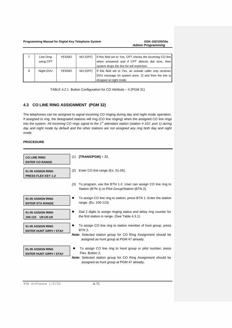
Programming Manual for Digital Key Telephone System GDK-162/100/34e
Admin Programming
99A Software 1/6/00 A-75
7 Line Drop
using CPT
YES/NO NO (OFF) If this field set to Yes, CPT checks the incoming CO line
when answered and if CPT detects dial tone, then
system drops the line for toll restriction.
8 Night DVU YES/NO NO (OFF) If this field set to Yes, an outside caller only receives
DVU message (in system annc. 2) and then the line is
dropped at night mode.
TABLE 4.2.1 Button Configuration for CO Attribute – II (PGM 31)
4.3 CO LINE RING ASSIGNMENT (PGM 32)
The telephones can be assigned to signal incoming CO ringing during day and night mode operation.
If assigned to ring, the designated stations will ring (CO line ringing) when the assigned CO line rings
into the system. All incoming CO rings signal to the 1st attendant station (station # 101: port 1) during
day and night mode by default and the other stations are not assigned any ring both day and night
mode.
PROCEDURE
CO LINE RING
ENTER CO RANGE
(1) [TRANS/PGM] + 32.
01-05 ASSIGN RING
PRESS FLEX KEY 1-2
(2) Enter CO line range (Ex. 01-05).
(3) To program, use the BTN 1-2. User can assign CO line ring to
Station (BTN 1) or Pilot Group/Station (BTN 2).
01-05 ASSIGN RING
ENTER STA RANGE
To assign CO line ring to station, press BTN 1. Enter the station
range. (Ex. 100-110)
01-05 ASSIGN RING
100-110 U0:U0:U0
Dial 2 digits to assign ringing status and delay ring counter for
the first station in range. (See Table 4.3.1)
01-05 ASSIGN RING
ENTER HUNT GRP# / STA#
To assign CO line ring to station member of hunt group, press
BTN 2.
Note: Selected station group for CO Ring Assignment should be
assigned as hunt group at PGM 47 already.
01-05 ASSIGN RING
ENTER HUNT GRP# / STA#
To assign CO line ring to Hunt group or pilot number, press
Flex. Button 2.
Note: Selected station group for CO Ring Assignment should be
assigned as hunt group at PGM 47 already.

Programming Manual for Digital Key Telephone System GDK-162/100/34e
Admin Programming
99A Software 1/6/00 A-76
01-05 ASSIGN RING
HUNT 620 U:U:U
To assign CO ring to the Hunt group, dial “y” to assign ringing
mode for the selected hunt group. (See Table 4.3.1)
(There is no delay ring available in this case.)
01-05 ASSIGN RING
STA 120 U:U:U
To assign CO ring to any station of hunt group, enter a station
number. Dial “y” to assign ringing mode for the selected
station. (See Table 4.3.1)
CO LINE RING
ENTER CO RANGE
(4) Press the [HOLD/SAVE] button for updating database
permanently. System goes to Step 1).
01-05 ASSIGN RING
PRESS FLEX KEY 1-2
(5) Press [] button instead of the [HOLD/SAVE] button, then
system goes to step 2) with no updating system memory.
UD ITEM RANGE REMARK LCD DISPLAY FORMAT
U Ringing Status 0-4
0: Unassigned
1: Day Ring assignment
2: Night Ring assignment
3: Day & Night Ring assignment
4: On-demand Ring assignment
U : Unassigned
D : Day Ring
N : Night Ring
O : On-Demand Ring
H : Ring assigned to Hunt group
S : Ring assigned to Station
D Delay Ring
Counter
0-9 about 3sec./counter Note: for station only, not hunt group
TABLE 4.3.1 Description of Data „y‟ & „d‟ (PGM 32)

Programming Manual for Digital Key Telephone System GDK-162/100/34e
Admin Programming
99A Software 1/6/00 A-77
4.4 CO FLASH TIMER (PGM 33)
User can initiate an open loop or ground flash across a CO line for receiving CO dial tone or
transferring a PABX. In this case, flash maintains for CO Flash Timer.
PROCEDURE
CO FLASH TIMER
ENTER CO RANGE
(1) [TRANS/PGM] + 33.
CO FLASH TIMER 00-30
01-05 : 05 (100MS)
(2) Enter CO line range (Ex.01-05). LCD shows current flash times.
(3) Enter CO Flash Timer value (00-30), then entered data will be
displayed on LCD. (Default: 05 (100ms base))
CO FLASH TIMER
ENTER CO RANGE
(4) Press the [HOLD/SAVE] button for updating database
permanently.
CO FLASH TIMER
ENTER CO RANGE
Press [] button instead of the [HOLD/SAVE] button, then
system goes to step (1) with no updating system memory.
4.5 OPEN LOOP DETECT TIMER (PGM 34)
The system can recognize the status of a CO line (normally open or closed) by open loop detect timer.
It will be operated when open loop signal is received from PX. (Ex. disconnecting a line)
PROCEDURE
OPEN LOOP DETECT
ENTER CO RANGE
(1) [TRANS/PGM] + 34.
OPEN LOOP DETECT 00-20
01-05 : 00 (100MS)
(2) Enter CO line range (Ex. 01-05). LCD shows current open loop
detect time.
(3) Enter Open Loop Detect Timer value (00-20), then entered data
will be displayed on LCD. (Default : 00 (100ms base))
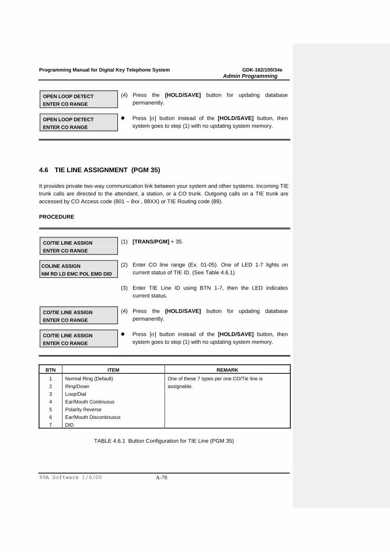
Programming Manual for Digital Key Telephone System GDK-162/100/34e
Admin Programming
99A Software 1/6/00 A-78
OPEN LOOP DETECT
ENTER CO RANGE
(4) Press the [HOLD/SAVE] button for updating database
permanently.
OPEN LOOP DETECT
ENTER CO RANGE
Press [] button instead of the [HOLD/SAVE] button, then
system goes to step (1) with no updating system memory.
4.6 TIE LINE ASSIGNMENT (PGM 35)
It provides private two-way communication link between your system and other systems. Incoming TIE
trunk calls are directed to the attendant, a station, or a CO trunk. Outgoing calls on a TIE trunk are
accessed by CO Access code (801 – 8xx , 88XX) or TIE Routing code (89).
PROCEDURE
CO/TIE LINE ASSIGN
ENTER CO RANGE
(1) [TRANS/PGM] + 35.
COLINE ASSIGN
NM RD LD EMC POL EMD DID
(2) Enter CO line range (Ex. 01-05). One of LED 1-7 lights on
current status of TIE ID. (See Table 4.6.1)
(3) Enter TIE Line ID using BTN 1-7, then the LED indicates
current status.
CO/TIE LINE ASSIGN
ENTER CO RANGE
(4) Press the [HOLD/SAVE] button for updating database
permanently.
CO/TIE LINE ASSIGN
ENTER CO RANGE
Press [] button instead of the [HOLD/SAVE] button, then
system goes to step (1) with no updating system memory.
BTN ITEM REMARK
1
2
3
4
5
6
7
Normal Ring (Default)
Ring/Down
Loop/Dial
Ear/Mouth Continuous
Polarity Reverse
Ear/Mouth Discontinuous
DID
One of these 7 types per one CO/Tie line is
assignable.
TABLE 4.6.1 Button Configuration for TIE Line (PGM 35)
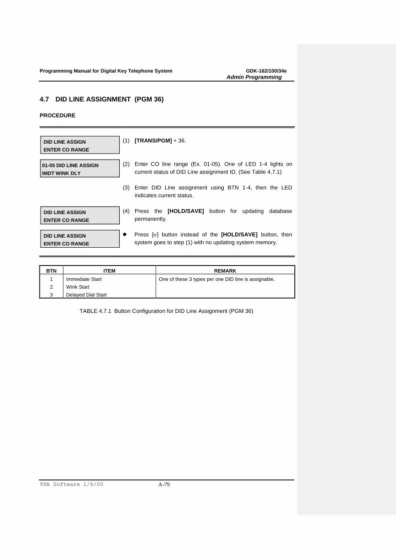
Programming Manual for Digital Key Telephone System GDK-162/100/34e
Admin Programming
99A Software 1/6/00 A-79
4.7 DID LINE ASSIGNMENT (PGM 36)
PROCEDURE
DID LINE ASSIGN
ENTER CO RANGE
(1) [TRANS/PGM] + 36.
01-05 DID LINE ASSIGN
IMDT WINK DLY
(2) Enter CO line range (Ex. 01-05). One of LED 1-4 lights on
current status of DID Line assignment ID. (See Table 4.7.1)
(3) Enter DID Line assignment using BTN 1-4, then the LED
indicates current status.
DID LINE ASSIGN
ENTER CO RANGE
(4) Press the [HOLD/SAVE] button for updating database
permanently.
DID LINE ASSIGN
ENTER CO RANGE
Press [] button instead of the [HOLD/SAVE] button, then
system goes to step (1) with no updating system memory.
BTN ITEM REMARK
1
2
3
Immediate Start
Wink Start
Delayed Dial Start
One of these 3 types per one DID line is assignable.
TABLE 4.7.1 Button Configuration for DID Line Assignment (PGM 36)

Programming Manual for Digital Key Telephone System GDK-162/100/34e
Admin Programming
99A Software 1/6/00 A-80
4.8 ISDN CO LINE ATTRIBUTES (PGM 37)
PROCEDURE
ISDN CO LINE ATTRIBUTES
ENTER CO RANGE
(1) [TRANS/PGM] + 37.
ISDN CO LINE ATTRIBUTES
PRESS FLEX KEY (1-2)
(2) Enter CO line range (Ex. 01-05).
01-05: COLP FOR ISDN CO
COLP : NOT ASSIGN
(3) To program COLP, press BTN 1 and enter related data for
setting COLP, then entered data will be displayed on LCD.
01-05: IGNORED DGT NO
DID_RN : 00
(4) To program number of DID digits that will be ignored, press
BTN 2 and enter related data, then it will be displayed entered
data on LCD.
ISDN CO LINE ATTRIBUTES
ENTER CO RANGE
(5) Press the [HOLD/SAVE] button for updating database
permanently.
ISDN CO LINE ATTRIBUTES
ENTER CO RANGE
Press [] button instead of the [HOLD/SAVE] button, then
system goes to step (1) with no updating system memory.
BTN ITEM RANGE DEFAULT REMARK
1 COLP 00-11 00 00: Not assigned
01-10 indicate an entry of Outgoing CLIP table (PGM 09)
11: Extension number
2 DID_RN
00-99 00 00: Do not ignore
01-99 indicate a ignored called party number
(DID_RN: DID Remove number from called party
information)
TABLE 4.8.1 ISDN CO Line Attribute (PGM 37)

Programming Manual for Digital Key Telephone System GDK-162/100/34e
Admin Programming
99A Software 1/6/00 A-81
4.9 CO LINE ATTRIBUTE – IV (PGM 38)
PROCEDURE
CO LINE ATT 4
ENTER CO RANGE
(1) [TRANS/PGM] + 38.
CO LINE ATTRIBUTES 4
PRESS FLEX KEY (1-8)
(2) Enter CO line range (Ex. 01-05). LCD prompts to press Flex.
BTN (1-8).
01-05 : CO RING TYPE
RING: 0
(3) To program the CO Line ring type, press BTN 1 and dial ring
type 1-4. By default ring type is not assigned (0).
To program the CO Line MOH, press BTN 2 and enter MOH
number (0) then entered data will be displayed on LCD. (MOH
0 – MOH 9)
To program the DTONE, press the 3rd
button. And press 0 or 1.
01-05 : RING BACK CAUSE
HANDLING: DISABLE
(3)(4)To provide tone (Busy/Error/Ring Back/Announce) in R2/ISDN
PX which does not give tone, press Flexible BTN 4~7. It
determines tone type. (Ex. When the Cause is ring back)
01-05 : ERR CAUSE
HANDLING: DISABLE
(3)(5)Ex. When the Cause is error, press Flex. BTN 5.
01-05 : BUSY CAUSE
HANDLING: DISABLE
(3)(6)Ex. When the Cause is busy, press Flex. BTN 6.
01-05 : ANNC CAUSE
HANDLING: DISABLE
(3)(7)Ex. When the Cause us announcement, press Flex. BTN 7.
01-05 : CO PAGE ENABLE
ON (1)/OFF(0): 1
(3)(8)To enable/disable CO page, press Flex. BTN 8.
CO LINE ATT 4
ENTER CO RANGE
(4)(9)Press the [HOLD/SAVE] button for updating database
permanently.
CO LINE ATT 4
ENTER CO RANGE
Press [] button instead of the [HOLD/SAVE] button, then
system goes to PGM number enter mode without updating
system memory. Enter new PGM number for programming
another parameters.
Formatted: Bullets and Numbering
Formatted: Bullets and Numbering
Formatted: Bullets and Numbering
Formatted: Bullets and Numbering
Formatted: Bullets and Numbering
Formatted: Bullets and Numbering
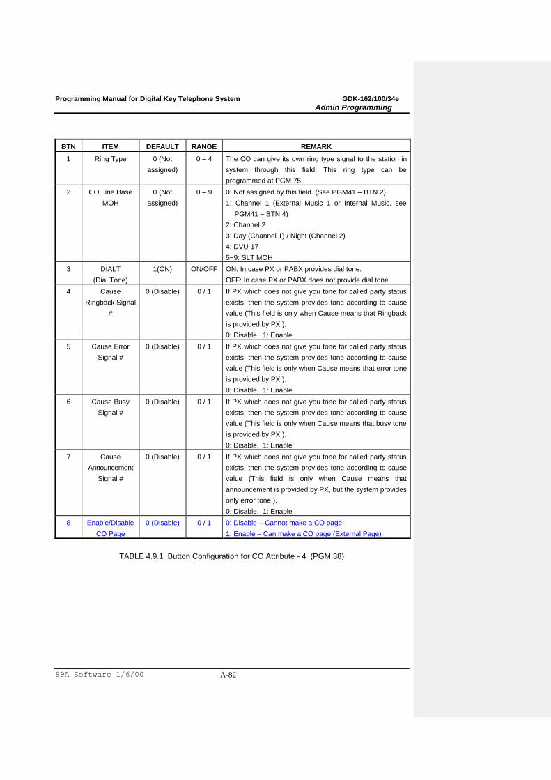
Programming Manual for Digital Key Telephone System GDK-162/100/34e
Admin Programming
99A Software 1/6/00 A-82
BTN ITEM DEFAULT RANGE REMARK
1 Ring Type 0 (Not
assigned)
0 – 4 The CO can give its own ring type signal to the station in
system through this field. This ring type can be
programmed at PGM 75.
2 CO Line Base
MOH
0 (Not
assigned)
0 – 9 0: Not assigned by this field. (See PGM41 – BTN 2)
1: Channel 1 (External Music 1 or Internal Music, see
PGM41 – BTN 4)
2: Channel 2
3: Day (Channel 1) / Night (Channel 2)
4: DVU-17
5~9: SLT MOH
3 DIALT
(Dial Tone)
1(ON) ON/OFF ON: In case PX or PABX provides dial tone.
OFF: In case PX or PABX does not provide dial tone.
4 Cause
Ringback Signal
#
0 (Disable) 0 / 1 If PX which does not give you tone for called party status
exists, then the system provides tone according to cause
value (This field is only when Cause means that Ringback
is provided by PX.).
0: Disable, 1: Enable
5 Cause Error
Signal #
0 (Disable) 0 / 1 If PX which does not give you tone for called party status
exists, then the system provides tone according to cause
value (This field is only when Cause means that error tone
is provided by PX.).
0: Disable, 1: Enable
6 Cause Busy
Signal #
0 (Disable) 0 / 1 If PX which does not give you tone for called party status
exists, then the system provides tone according to cause
value (This field is only when Cause means that busy tone
is provided by PX.).
0: Disable, 1: Enable
7 Cause
Announcement
Signal #
0 (Disable) 0 / 1 If PX which does not give you tone for called party status
exists, then the system provides tone according to cause
value (This field is only when Cause means that
announcement is provided by PX, but the system provides
only error tone.).
0: Disable, 1: Enable
8 Enable/Disable
CO Page
0 (Disable) 0 / 1 0: Disable – Cannot make a CO page
1: Enable – Can make a CO page (External Page)
TABLE 4.9.1 Button Configuration for CO Attribute - 4 (PGM 38)
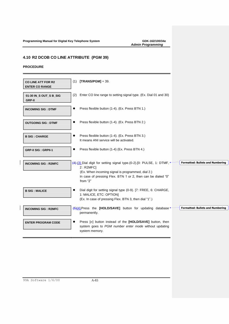
Programming Manual for Digital Key Telephone System GDK-162/100/34e
Admin Programming
99A Software 1/6/00 A-83
4.10 R2 DCOB CO LINE ATTRIBUTE (PGM 39)
PROCEDURE
CO LINE ATT FOR R2
ENTER CO RANGE
(1) [TRANS/PGM] + 39.
01-30 IN_S OUT_S B_SIG
GRP-II
(2) Enter CO line range to setting signal type. (Ex. Dial 01 and 30)
INCOMING SIG : DTMF
Press flexible button (1-4). (Ex. Press BTN 1.)
OUTGOING SIG : DTMF
Press flexible button (1-4). (Ex. Press BTN 2.)
B SIG : CHARGE
Press flexible button (1-4). (Ex. Press BTN 3.)
It means ANI service will be activated.
GRP-II SIG : GRPII-1
Press flexible button (1-4) (Ex. Press BTN 4.)
INCOMING SIG : R2MFC
(4) (3) Dial digit for setting signal type.(0-2).[0: PULSE, 1: DTMF,
2 : R2MFC]
(Ex. When incoming signal is programmed, dial 2.)
In case of pressing Flex. BTN 1 or 2, then can be dialed “0”
from “2”
B SIG : MALICE
Dial digit for setting signal type (0-9). [7: FREE, 6: CHARGE,
1: MALICE, ETC: OPTION]
(Ex. In case of pressing Flex. BTN 3, then dial “1”.)
INCOMING SIG : R2MFC
(5)(4) Press the [HOLD/SAVE] button for updating database
permanently.
ENTER PROGRAM CODE
Press [] button instead of the [HOLD/SAVE] button, then
system goes to PGM number enter mode without updating
system memory.
Formatted: Bullets and Numbering
Formatted: Bullets and Numbering
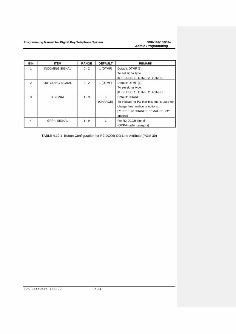
Programming Manual for Digital Key Telephone System GDK-162/100/34e
Admin Programming
99A Software 1/6/00 A-84
BIN ITEM RANGE DEFAULT REMARK
1 INCOMING SIGNAL 0 - 2 1 (DTMF) Default: DTMF (1)
To set signal type.
[0 : PULSE, 1 : DTMF, 2 : R2MFC]
2 OUTGOING SIGNAL 0 - 2 1 (DTMF) Default: DTMF (1)
To set signal type.
[0 : PULSE, 1 : DTMF, 2 : R2MFC]
3 B SIGNAL 1 - 9 6
(CHARGE)
Default: CHARGE
To indicate to PX that this line is used for
charge, free, malice or options.
[7: FREE, 6: CHARGE, 1: MALICE, etc:
options]
4 GRP-II SIGNAL 1 - 9 1 For R2 DCOB signal
(GRP-II caller category)
TABLE 4.10.1 Button Configuration for R2 DCOB CO Line Attribute (PGM 39)
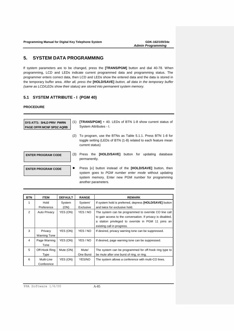
Programming Manual for Digital Key Telephone System GDK-162/100/34e
Admin Programming
99A Software 1/6/00 A-85
5. SYSTEM DATA PROGRAMMING
If system parameters are to be changed, press the [TRANS/PGM] button and dial 40-78. When
programming, LCD and LEDs indicate current programmed data and programming status. The
programmer enters correct data, then LCD and LEDs show the entered data and the data is stored in
the temporary buffer area. After all, press the [HOLD/SAVE] button, all data in the temporary buffer
(same as LCD/LEDs show their status) are stored into permanent system memory.
5.1 SYSTEM ATTRIBUTE - I (PGM 40)
PROCEDURE
SYS ATT1: SHLD PRIV PWRN
PAGE OFFR MCNF SPDZ AQRB
(1) [TRANS/PGM] + 40. LEDs of BTN 1-8 show current status of
System Attributes - I.
(2) To program, use the BTNs as Table 5.1.1. Press BTN 1-8 for
toggle setting (LEDs of BTN (1-8) related to each feature mean
current status)
ENTER PROGRAM CODE
(3) Press the [HOLD/SAVE] button for updating database
permanently.
ENTER PROGRAM CODE
Press [] button instead of the [HOLD/SAVE] button, then
system goes to PGM number enter mode without updating
system memory. Enter new PGM number for programming
another parameters.
BTN ITEM DEFAULT RANGE REMARK
1 Hold
Preference
System
(ON)
System/
Exclusive
If system hold is preferred, depress [HOLD/SAVE] button
and twice for exclusive hold.
2 Auto Privacy YES (ON) YES / NO The system can be programmed to override CO line call
to gain access to the conversation. If privacy is disabled,
a station privileged to override in PGM 11 joins an
existing call in progress.
3 Privacy
Warning Tone
YES (ON) YES / NO If desired, privacy warning tone can be suppressed.
4 Page Warning
Tone
YES (ON) YES / NO If desired, page warning tone can be suppressed.
5 Off-Hook Ring
Type
Mute (ON) Mute/
One Burst
The system can be programmed for off-hook ring type to
be mute after one burst of ring, or ring.
6 Multi-Line
Conference
YES (ON) YES/NO The system allows a conference with multi-CO lines.

Programming Manual for Digital Key Telephone System GDK-162/100/34e
Admin Programming
99A Software 1/6/00 A-86
7 System Speed
Toll Check
YES (ON) YES/NO The system can be programmed common speed zone
(bin 300-399) toll check to free or restrict.
8 Attendant
Queuing Ring
Back Tone
NO (OFF) YES/NO YES: The station will be present ring back tone when
calling busy attendant station.
NO : The station will be present MOH, hold tone or DVU-
17 by system database (PGM 41-BTN 2)
TABLE 5.1.1 Button Configuration for System Attribute - I (PGM 40)
5.2 SYSTEM ATTRIBUTE - II (PGM 41)
PROCEDURE
SYS ATT2: BGM1 MOH1 BOX1
IMUSIC LG(KOR) CLIP CAMP
(1) [TRANS/PGM] + 41. LCD and LED of BTN 4, 6~7 show
current status of that attribute.
(2) To program, use the BTNs as Table 5.2.1. Press BTN 1-3, 5
and enter related data then entered data will be displayed on
LCD. Press BTN 4, 6~7 for toggle setting. (LED of BTN 4, 6~7
means current status)
ENTER PROGRAM CODE
(3) Press the [HOLD/SAVE] button for updating database
permanently.
ENTER PROGRAM CODE
Press [] button instead of the [HOLD/SAVE] button, then
system goes to PGM number enter mode without updating
system memory.

Programming Manual for Digital Key Telephone System GDK-162/100/34e
Admin Programming
99A Software 1/6/00 A-87
BTN NO. ITEM DEFAULT DATA REMARK
1 No. of BGM Channel 1
2
0-9 0 : No BGM,
1 : Music 1, 2 : Music 2
3 : Day – Music 1, Night - Music 2
4 : DVU BGM
5~9 : SLT BGM
2 Music on Hold Port 1
2
0-9 0 : Hold Tone
1 : Music 1, 2 : Music 2
3 : Day - Music 1, Night - Music 2
4 : DVU MOH
5~9 : SLT MOH (*)
3 ICM Box Music Port 1 0-9 0: No music,
1 : Music 1, 2 : Music 2
3 : Day - Music 1, Night - Music 2
4 : DVU Music
5~9 : SLT Music (*)
4 Music Source Assign Internal (LED On) Internal / External
5 LCD Display Language 01
(Korean)
00-24 00: English, 01: Korean,
02: Italian, 04:Swedish,
05 : Norwegian, 06: Finnish,
07: Dutch, 08: Spanish,
10: Danish
11: Invalid (162), Germany (100/FPII)
13: Estonia, 20: Russian
22(162), 24(100/FPII) : Portuguese
- Condition: Following codes should
be not registered; 03, 09, 12, 14, 15,
16, 17, 18, 19, 21
6 Calling Number
Identification
No (LED Off)
7 Camp-On Tone Assign No (LED Off) 0/1 0: Ringback tone is heard in camp-on.
1: MOH is heard in camp-on.
8
(Only
100/FPII)
SMDR 0 0 – 4 Determines the number of digits to be
hidden in SMDR from the last digit.
(*) Note: Hardware device (MOHU) is required. (See also PGM #1)
TABLE 5.2.1 Button Configuration for System Attribute - II (PGM 41)
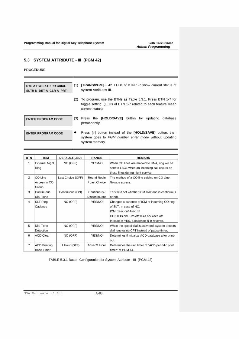
Programming Manual for Digital Key Telephone System GDK-162/100/34e
Admin Programming
99A Software 1/6/00 A-88
5.3 SYSTEM ATTRIBUTE - III (PGM 42)
PROCEDURE
SYS ATT3: EXTR RR CDIAL
SLTR D_DET A_CLR A_PRT
(1) [TRANS/PGM] + 42. LEDs of BTN 1-7 show current status of
system Attributes-III.
(2) To program, use the BTNs as Table 5.3.1. Press BTN 1-7 for
toggle setting. (LEDs of BTN 1-7 related to each feature mean
current status)
ENTER PROGRAM CODE
(3) Press the [HOLD/SAVE] button for updating database
permanently.
ENTER PROGRAM CODE
Press [] button instead of the [HOLD/SAVE] button, then
system goes to PGM number enter mode without updating
system memory.
BTN ITEM DEFAULT(LED) RANGE REMARK
1 External Night
Ring
NO (OFF) YES/NO When CO lines are marked to UNA, ring will be
sent to LBC1 when an incoming call occurs on
those lines during night service.
2 CO Line
Access in CO
Group
Last Choice (OFF) Round Robin
/ Last Choice
The method of a CO line seizing on CO Line
Groups access.
3 Continuous
Dial-Tone
Continuous (ON) Continuous /
Discontinuous
This field set whether ICM dial tone is continuous
or not.
4 SLT Ring
Cadence
NO (OFF) YES/NO Changes a cadence of ICM or incoming CO ring
of SLT. In case of NO,
ICM: 1sec on/ 4sec off
CO : 0.4s on/ 0.2s off/ 0.4s on/ 4sec off
In case of YES, a cadence is in reverse.
5 Dial Tone
Detection
NO (OFF) YES/NO When the speed dial is activated, system detects
dial tone using CPT instead of pause timer.
6 ACD Clear NO (OFF) YES/NO Determines if initialize ACD database after print-
out.
7 ACD Printing
Base Timer
1 Hour (OFF) 10sec/1 Hour Determines the unit timer of "ACD periodic print
timer" at PGM 44.
TABLE 5.3.1 Button Configuration for System Attribute - III (PGM 42)

Programming Manual for Digital Key Telephone System GDK-162/100/34e
Admin Programming
99A Software 1/6/00 A-89
5.4 SYSTEM TIMERS - I (PGM 43)
PROCEDURE
SYSTEM TIMER 1
PRESS FLEX KEY (1-24)
(1) [TRANS/PGM] + 43.
(2) To program, use the BTNs as Table 5.4.1. Press one of BTN 1-
24 and related data. (LED of selected Flex. Button will be lit.)
SYSTEM TIMER 1
PRESS FLEX KEY (1-24)
(3) Press the [HOLD/SAVE] button for updating database
permanently.
SYSTEM TIMER 1
PRESS FLEX KEY (1-24)
Press [] button instead of the [HOLD/SAVE] button, then
system goes to step (1) without updating system memory.
BTN ITEM DEFAULT RANGE REMARK
1 Exc. Hold Recall Timer 060 000 - 300
(3 Digits)
Determines the amount of time before a call placed on
exclusive hold will recall the station placing the hold.
2 Sys Hold Recall Timer 030 000 - 300
(3 Digits)
Determines the amount of time before a call placed on
system hold will recall the station placing the hold.
3 Transfer Recall Timer 030 000 - 300
(3 Digits)
Determines the amount of time a transferred call will
ring at the station receiving the transfer and how long it
will recall the station transferring the call.
4 I-Recall Timer 030 000 - 300
(3 Digits)
Determines the amount of time before a call recalls the
attendant.
5 Attendant Recall Timer 01 00 - 60
(2 Digits)
Determines the amount of time before system
disconnects the call.
6 CO Ring Detect Timer 2 1 - 9
(1 Digit)
The CO Ring Detect Timer controls the time necessary
to detect an outside line as ringing into the system.
7 Pause Timer 3 1 - 9
(1 Digit)
Determines the length of the pause for use with
automatically sent digits or other speed dialing.
8 CO Release Guard
Timer
020 010 - 150
(3 Digits)
The CO Release Guard Timer controls the time
necessary to guarantee idle loop state when the line is
released.
9 CO Warning Tone
Timer
180 060 - 900
(3 Digits)
Determines the amount of time before receiving
warning tone in order to remind the call elapsed time in
case of outgoing CO conversations (Only for Korea).
10 CO Dial Delay Timer 01 00 - 99
(2 Digits)
Voice connection to the outside party will be made after
this timer. This can be used to prevent illegal dialing in
case of slow response from the Central Office Line or
PBX.
11 Call Park Recall Timer 120 000 - 600
(3 Digits)
Determines the amount of time before a call placed in a
call park location will recall the station placing the park.
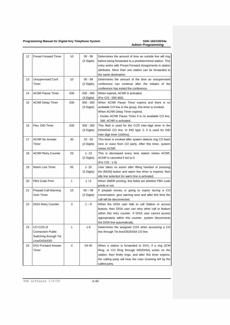
Programming Manual for Digital Key Telephone System GDK-162/100/34e
Admin Programming
99A Software 1/6/00 A-90
12 Preset Forward Timer 10 00 - 99
(2 Digits)
Determines the amount of time an outside line will ring
before being forwarded to a predetermined station. This
entry works with Preset Forward Assignments in station
attributes. More than one station can be forwarded to
the same destination.
13 Unsupervised Conf.
Timer
10 00 - 99
(2 Digits)
Determines the amount of the time an unsupervised
conference can continue after the initiator of the
conference has exited the conference.
14 ACNR Pause Timer 030 030 - 300
(3 Digits)
When expired, ACNR is activated.
(For CIS : 050-300)
15 ACNR Delay Timer 030 000 - 300
(3 Digits)
When ACNR Pause Timer expires and there is no
available CO line in the group, this timer is invoked.
When ACNR Delay Timer expired,
- Invoke ACNR Pause Timer if is no available CO line.
Still, ACNR is activated.
16 Flex. DID Timer 030 000 - 300
(3 Digits)
This field is used for the CCR inter-digit timer in the
DISA/DID CO line. In DID type 2, it is used for DID
inter-digit timer (100ms).
17 ACNR No Answer
Timer
30 10 - 50
(2 Digits)
This timer is invoked after system detects ring CO back
tone or voice from CO party. After this timer, system
retries ACNR.
18 ACNR Retry Counter 03 1- 13
(2 Digits)
This is decreased every time station retries ACNR,
ACNR is canceled if set to 0.
(For CIS : 1-9)
19 Warm Line Timer 05 1- 20
(2 Digits)
User takes no action after lifting handset or pressing
the [MON] button and warm line timer is expired, then
idle line selection for warm line is activated.
20 PBX-Code Print 1 1 / 0 When SMDR printing, this fields set whether PBX code
prints or not.
21 Prepaid Call Warning
Over Timer
15 00 – 99
(2 Digits)
If prepaid money is going to expire during a CO
conversation, give warning tone and after this time the
call will be disconnected.
22 DISA Retry Counter 3 1 – 9 When the DISA user fails to call Station or access
feature, then DISA user can retry other call or feature
within this retry counter. If DISA user cannot access
appropriately within this counter, system disconnects
the DISA line automatically.
23 CO COS of
Connection Public
Switching through Tie
Line/DISA/DID
1 1-6 Determines the assigned COS when accessing a CO
line through Tie line/DID/DISA CO line.
24 DVU Forward Answer
Timer
4 04-40 When a station is forwarded to DVU, if a ring (ICM
Ring, or CO Ring through DID/DISA) exists on the
station, then firstly rings, and after this timer expires,
the calling party will hear the User Greeting left by the
called party.
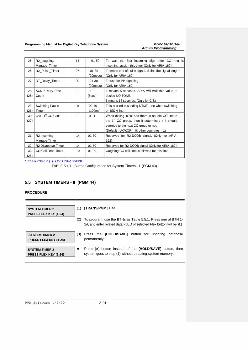
Programming Manual for Digital Key Telephone System GDK-162/100/34e
Admin Programming
99A Software 1/6/00 A-91
25 R2_outgoing
Manage_Timer
14 01-50 To wait the first incoming digit after CO ring is
incoming, assign this timer (Only for ARIA-162)
26 R2_Pulse_Timer 07 01-30
(20msec)
To make end of pulse signal, define the signal length.
(Only for ARIA-162)
27 DT_Delay_Timer 20 01-30
(20msec)
To use for PP signaling
(Only for ARIA-162)
28
(25)
ACNR Retry Time
Count
1 1-9
(5sec)
1 means 5 seconds, ARIA will wait this value to
decide NO TONE.
3 means 15 seconds. (Only for CIS)
29
(26)
Switching Pause
Timer
0 00-40
(100ms)
This is used in sending DTMF tone when switching
on ISDN line.
30
(27)
OVR 1st CO GRP 1 0 - 1 When dialing „9‟/„0‟ and there is no idle CO line in
the 1st CO group, then it determines if it should
override to the next CO group or not.
(Default : UK/KOR = 0, other countries = 1)
31 R2 Incoming
Manage Timer
14 01-50 Reserved for R2-DCOB signal. (Only for ARIA-
162)
32 R2 Disappear Timer 14 01-50 Reserved for R2-DCOB signal (Only for ARIA-162)
33
(28)
CO Call Drop Timer 10 01-99 Outgoing CO call time is allowed for this time.
*. The number in ( ) is for ARIA-100/FPII.
TABLE 5.4.1 Button Configuration for System Timers - I (PGM 43)
5.5 SYSTEM TIMERS - II (PGM 44)
PROCEDURE
SYSTEM TIMER 2
PRESS FLEX KEY (1-24)
(1) [TRANS/PGM] + 44.
(2) To program, use the BTNs as Table 5.5.1. Press one of BTN 1-
24, and enter related data. (LED of selected Flex button will be lit.)
SYSTEM TIMER 2
PRESS FLEX KEY (1-24)
(3) Press the [HOLD/SAVE] button for updating database
permanently.
SYSTEM TIMER 2
PRESS FLEX KEY (1-24)
Press [] button instead of the [HOLD/SAVE] button, then
system goes to step (1) without updating system memory.
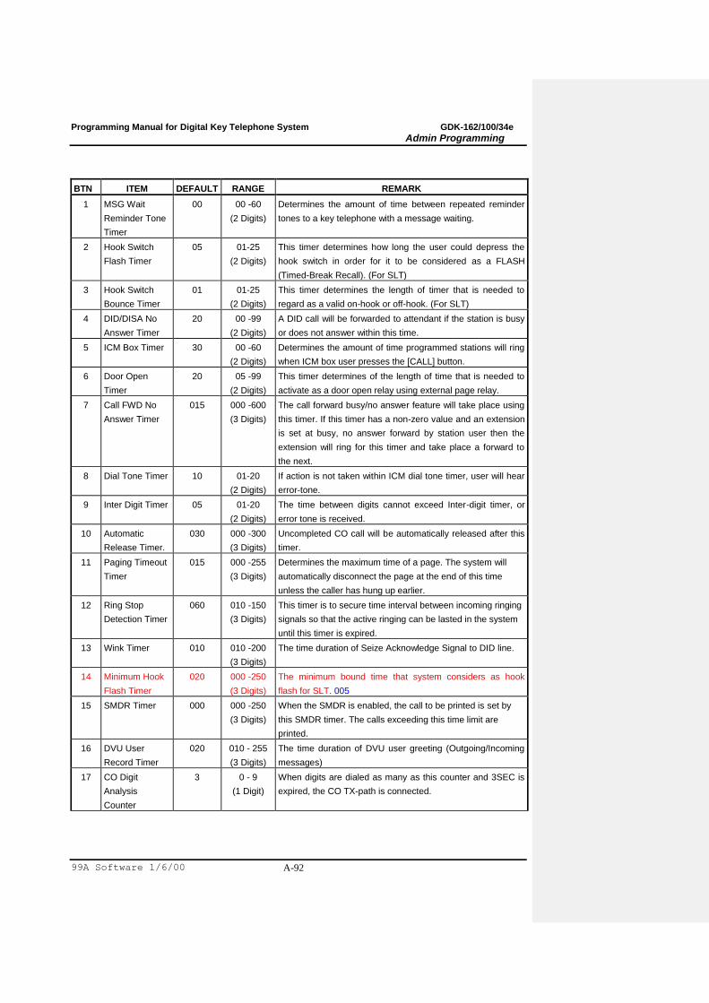
Programming Manual for Digital Key Telephone System GDK-162/100/34e
Admin Programming
99A Software 1/6/00 A-92
BTN ITEM DEFAULT RANGE REMARK
1 MSG Wait
Reminder Tone
Timer
00 00 -60
(2 Digits)
Determines the amount of time between repeated reminder
tones to a key telephone with a message waiting.
2 Hook Switch
Flash Timer
05 01-25
(2 Digits)
This timer determines how long the user could depress the
hook switch in order for it to be considered as a FLASH
(Timed-Break Recall). (For SLT)
3 Hook Switch
Bounce Timer
01 01-25
(2 Digits)
This timer determines the length of timer that is needed to
regard as a valid on-hook or off-hook. (For SLT)
4 DID/DISA No
Answer Timer
20 00 -99
(2 Digits)
A DID call will be forwarded to attendant if the station is busy
or does not answer within this time.
5 ICM Box Timer 30 00 -60
(2 Digits)
Determines the amount of time programmed stations will ring
when ICM box user presses the [CALL] button.
6 Door Open
Timer
20 05 -99
(2 Digits)
This timer determines of the length of time that is needed to
activate as a door open relay using external page relay.
7 Call FWD No
Answer Timer
015 000 -600
(3 Digits)
The call forward busy/no answer feature will take place using
this timer. If this timer has a non-zero value and an extension
is set at busy, no answer forward by station user then the
extension will ring for this timer and take place a forward to
the next.
8 Dial Tone Timer 10 01-20
(2 Digits)
If action is not taken within ICM dial tone timer, user will hear
error-tone.
9 Inter Digit Timer 05 01-20
(2 Digits)
The time between digits cannot exceed Inter-digit timer, or
error tone is received.
10 Automatic
Release Timer.
030 000 -300
(3 Digits)
Uncompleted CO call will be automatically released after this
timer.
11 Paging Timeout
Timer
015 000 -255
(3 Digits)
Determines the maximum time of a page. The system will
automatically disconnect the page at the end of this time
unless the caller has hung up earlier.
12 Ring Stop
Detection Timer
060 010 -150
(3 Digits)
This timer is to secure time interval between incoming ringing
signals so that the active ringing can be lasted in the system
until this timer is expired.
13 Wink Timer 010 010 -200
(3 Digits)
The time duration of Seize Acknowledge Signal to DID line.
14 Minimum Hook
Flash Timer
020 000 -250
(3 Digits)
The minimum bound time that system considers as hook
flash for SLT. 005
15 SMDR Timer 000 000 -250
(3 Digits)
When the SMDR is enabled, the call to be printed is set by
this SMDR timer. The calls exceeding this time limit are
printed.
16 DVU User
Record Timer
020 010 - 255
(3 Digits)
The time duration of DVU user greeting (Outgoing/Incoming
messages)
17 CO Digit
Analysis
Counter
3 0 - 9
(1 Digit)
When digits are dialed as many as this counter and 3SEC is
expired, the CO TX-path is connected.

Programming Manual for Digital Key Telephone System GDK-162/100/34e
Admin Programming
99A Software 1/6/00 A-93
BTN ITEM DEFAULT RANGE REMARK
18 ACD Print Timer 000 000 - 255
(3 Digits)
Determines the amount of time between repeated ACD
database prints. Zero means no print out.
19 Ring Phase
Timer
5 2 - 5
(1 Digit)
Determines the ring phase of SLT.
(5 SEC : 1SEC ON / 4SEC OFF)
20 Camp-on Recall
Timer
050 000 - 200
(3 Digits)
If a station transfers to busy station and hang up, this recall
timer is assigned.
21 Station Auto
Release Timer
060 000 - 200
(3 Digits)
If a station hears ring back tone and no action is taken, this
timer is assigned. When this timer is expired the station is
released.
22 DCOB Type 2 0 - 2 0 : Sweden/Cyprus 1: Italy 2: Korea/Australia
23 Ready Signal
timer
007 000 - 255 For DCOB Signal Timer (used at DCOB)
24 Erase Wake-Up
Fail Ring Timer
20 0-99 After a Wake-up fail ring invokes on the System Attendant,
the alarm ring exists during this timer. Then if this timer
expires, the alarm ring will be disappeared.
TABLE 5.5.1 Button Configuration for System Timers - II (PGM 44)
5.6 ADMIN PASSWORD (PGM 45)
Admin Password can be assigned to enter Admin Programming mode for only Administrator who
knows the Admin Password. It is not assigned by default.
PROCEDURE
ADMIN PASSWORD
....
(1) [TRANS/PGM] + 45.
ADMIN PASSWORD
1234
(2) To assign Admin Password, enter 4 digits number, then
entered admin password will be displayed on LCD. Otherwise
to delete the admin password, press the [SPEED] button. (Ex
1234)
ENTER PROGRAM CODE
(3) Press the [HOLD/SAVE] button for updating database
permanently.
ENTER PROGRAM CODE
Press [] button instead of the [HOLD/SAVE] button, then
system goes to PGM number enter mode without updating
system memory.
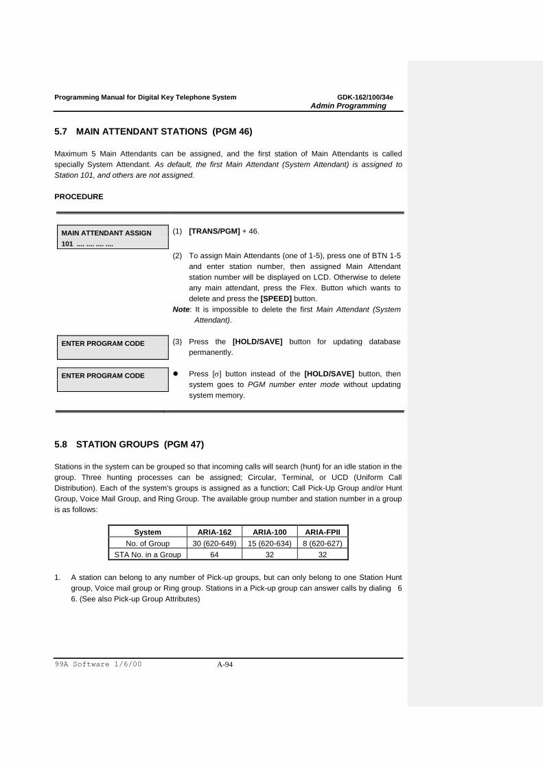
Programming Manual for Digital Key Telephone System GDK-162/100/34e
Admin Programming
99A Software 1/6/00 A-94
5.7 MAIN ATTENDANT STATIONS (PGM 46)
Maximum 5 Main Attendants can be assigned, and the first station of Main Attendants is called
specially System Attendant. As default, the first Main Attendant (System Attendant) is assigned to
Station 101, and others are not assigned.
PROCEDURE
MAIN ATTENDANT ASSIGN
101 .... .... .... ....
(1) [TRANS/PGM] + 46.
(2) To assign Main Attendants (one of 1-5), press one of BTN 1-5
and enter station number, then assigned Main Attendant
station number will be displayed on LCD. Otherwise to delete
any main attendant, press the Flex. Button which wants to
delete and press the [SPEED] button.
Note: It is impossible to delete the first Main Attendant (System
Attendant).
ENTER PROGRAM CODE
(3) Press the [HOLD/SAVE] button for updating database
permanently.
ENTER PROGRAM CODE
Press [] button instead of the [HOLD/SAVE] button, then
system goes to PGM number enter mode without updating
system memory.
5.8 STATION GROUPS (PGM 47)
Stations in the system can be grouped so that incoming calls will search (hunt) for an idle station in the
group. Three hunting processes can be assigned; Circular, Terminal, or UCD (Uniform Call
Distribution). Each of the system's groups is assigned as a function; Call Pick-Up Group and/or Hunt
Group, Voice Mail Group, and Ring Group. The available group number and station number in a group
is as follows:
System ARIA-162 ARIA-100 ARIA-FPII
No. of Group 30 (620-649) 15 (620-634) 8 (620-627)
STA No. in a Group 64 32 32
1. A station can belong to any number of Pick-up groups, but can only belong to one Station Hunt
group, Voice mail group or Ring group. Stations in a Pick-up group can answer calls by dialing 6
6. (See also Pick-up Group Attributes)
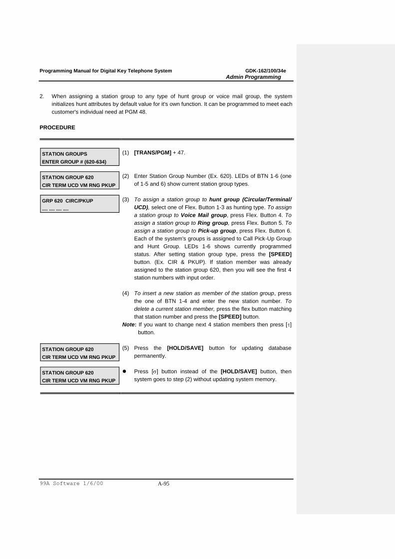
Programming Manual for Digital Key Telephone System GDK-162/100/34e
Admin Programming
99A Software 1/6/00 A-95
2. When assigning a station group to any type of hunt group or voice mail group, the system
initializes hunt attributes by default value for it's own function. It can be programmed to meet each
customer's individual need at PGM 48.
PROCEDURE
STATION GROUPS
ENTER GROUP # (620-634)
(1) [TRANS/PGM] + 47.
STATION GROUP 620
CIR TERM UCD VM RNG PKUP
(2) Enter Station Group Number (Ex. 620). LEDs of BTN 1-6 (one
of 1-5 and 6) show current station group types.
GRP 620 CIRC/PKUP
.... .... .... ....
(3) To assign a station group to hunt group (Circular/Terminal/
UCD), select one of Flex. Button 1-3 as hunting type. To assign
a station group to Voice Mail group, press Flex. Button 4. To
assign a station group to Ring group, press Flex. Button 5. To
assign a station group to Pick-up group, press Flex. Button 6.
Each of the system's groups is assigned to Call Pick-Up Group
and Hunt Group. LEDs 1-6 shows currently programmed
status. After setting station group type, press the [SPEED]
button. (Ex. CIR & PKUP). If station member was already
assigned to the station group 620, then you will see the first 4
station numbers with input order.
(4) To insert a new station as member of the station group, press
the one of BTN 1-4 and enter the new station number. To
delete a current station member, press the flex button matching
that station number and press the [SPEED] button.
Note: If you want to change next 4 station members then press []
button.
STATION GROUP 620
CIR TERM UCD VM RNG PKUP
(5) Press the [HOLD/SAVE] button for updating database
permanently.
STATION GROUP 620
CIR TERM UCD VM RNG PKUP
Press [] button instead of the [HOLD/SAVE] button, then
system goes to step (2) without updating system memory.
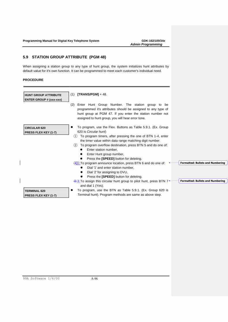
Programming Manual for Digital Key Telephone System GDK-162/100/34e
Admin Programming
99A Software 1/6/00 A-96
5.9 STATION GROUP ATTRIBUTE (PGM 48)
When assigning a station group to any type of hunt group, the system initializes hunt attributes by
default value for it's own function. It can be programmed to meet each customer's individual need.
PROCEDURE
HUNT GROUP ATTRIBUTE
ENTER GROUP # (xxx-xxx)
(1) [TRANS/PGM] + 48.
(2) Enter Hunt Group Number. The station group to be
programmed it's attributes should be assigned to any type of
hunt group at PGM 47. If you enter the station number not
assigned to hunt group, you will hear error tone.
CIRCULAR 620
PRESS FLEX KEY (1-7)
To program, use the Flex. Buttons as Table 5.9.1. (Ex. Group
620 is Circular hunt)
① To program timers, after pressing the one of BTN 1-4, enter
the timer value within data range matching digit number.
② To program overflow destination, press BTN 5 and do one of:
Enter station number,
Enter Hunt group number,
Press the [SPEED] button for deleting.
⑤③ To program announce location, press BTN 6 and do one of:
Dial '1' and enter station number,
Dial '2' for assigning to DVU,
Press the [SPEED] button for deleting.
⑥④ To assign this circular hunt group to pilot hunt, press BTN 7
and dial 1 (Yes).
TERMINAL 620
PRESS FLEX KEY (1-7)
To program, use the BTN as Table 5.9.1. (Ex. Group 620 is
Terminal hunt). Program methods are same as above step.
Formatted: Bullets and Numbering
Formatted: Bullets and Numbering
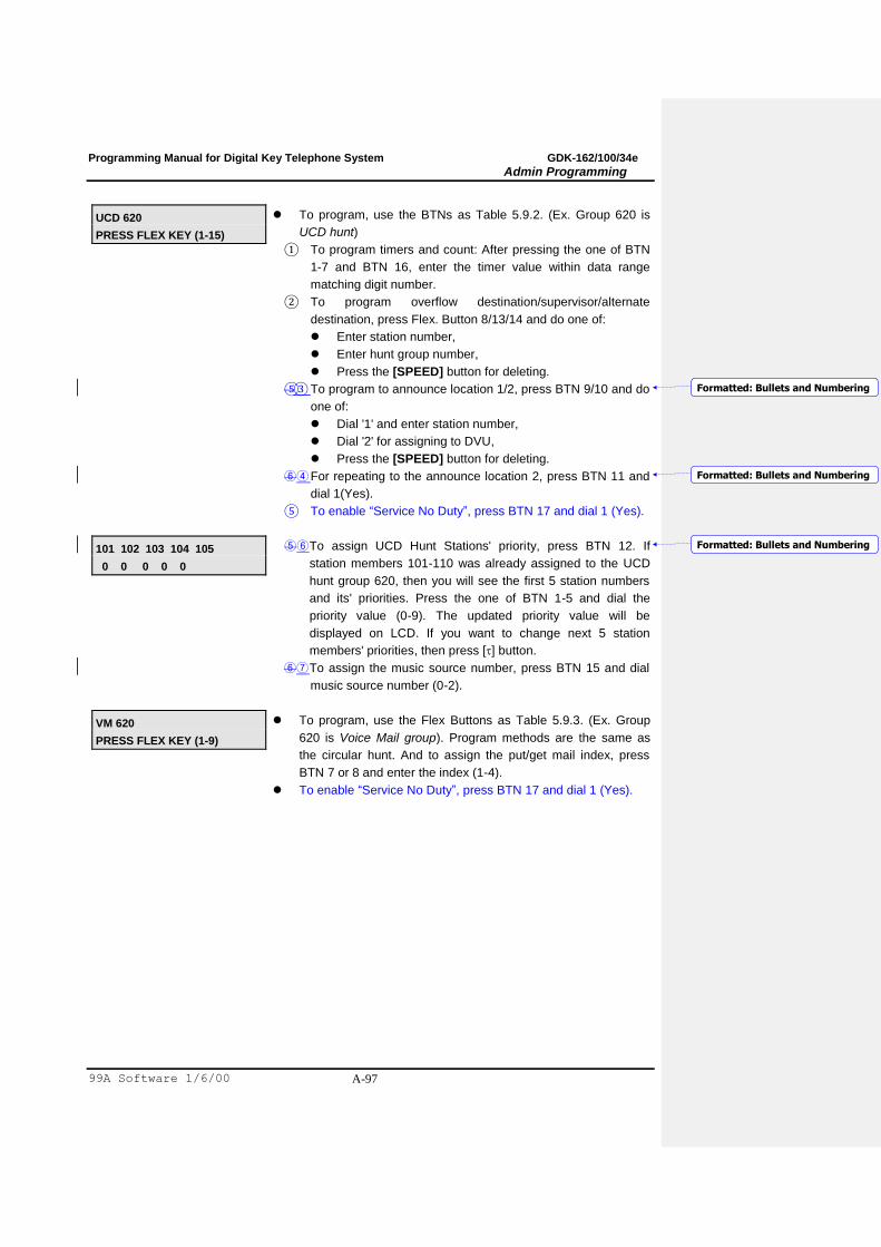
Programming Manual for Digital Key Telephone System GDK-162/100/34e
Admin Programming
99A Software 1/6/00 A-97
UCD 620
PRESS FLEX KEY (1-15)
To program, use the BTNs as Table 5.9.2. (Ex. Group 620 is
UCD hunt)
① To program timers and count: After pressing the one of BTN
1-7 and BTN 16, enter the timer value within data range
matching digit number.
② To program overflow destination/supervisor/alternate
destination, press Flex. Button 8/13/14 and do one of:
Enter station number,
Enter hunt group number,
Press the [SPEED] button for deleting.
⑤③ To program to announce location 1/2, press BTN 9/10 and do
one of:
Dial '1' and enter station number,
Dial '2' for assigning to DVU,
Press the [SPEED] button for deleting.
⑥④ For repeating to the announce location 2, press BTN 11 and
dial 1(Yes).
⑤ To enable “Service No Duty”, press BTN 17 and dial 1 (Yes).
101 102 103 104 105
0 0 0 0 0
⑤⑥ To assign UCD Hunt Stations' priority, press BTN 12. If
station members 101-110 was already assigned to the UCD
hunt group 620, then you will see the first 5 station numbers
and its' priorities. Press the one of BTN 1-5 and dial the
priority value (0-9). The updated priority value will be
displayed on LCD. If you want to change next 5 station
members' priorities, then press [] button.
⑥⑦ To assign the music source number, press BTN 15 and dial
music source number (0-2).
VM 620
PRESS FLEX KEY (1-9)
To program, use the Flex Buttons as Table 5.9.3. (Ex. Group
620 is Voice Mail group). Program methods are the same as
the circular hunt. And to assign the put/get mail index, press
BTN 7 or 8 and enter the index (1-4).
To enable “Service No Duty”, press BTN 17 and dial 1 (Yes).
Formatted: Bullets and Numbering
Formatted: Bullets and Numbering
Formatted: Bullets and Numbering

Programming Manual for Digital Key Telephone System GDK-162/100/34e
Admin Programming
99A Software 1/6/00 A-98
RING 620
PRESS FLEX KEY (1-5)
To program, use the Flex. Buttons as Table 5.9.4. (Ex. Group
620 is Ring group)
(1) To program the overflow timer, after pressing the BTN 1,
enter the timer value within data range matching digit
number.
(2) To program overflow destination press BTN 5 and do one of:
Enter station number,
Enter Hunt group number,
Press the [SPEED] button for deleting.
(5)(3)To assign the music source number, press BTN 15 and
dial music source number (0-2).
(4) To program DVU announcement time, press BTN 4 and
enter time value.
(5) To program DVU announcement location, press BTN 5 and
dial DVU announcement number (1~9).
(6) To enable “Service No Duty”, press BTN 17 and dial 1
(Yes).
STA PICKUP GROUP 620
AUTO_PCKP ALL_RING
To program branch group, first, assign pickup group at PGM 47
and program using the Flex Buttons as Table 5.9.5.
Flex. Button 1 Flex. Button 2
off don't care -> Normal Pickup Group
on off -> Auto pickup group
on on -> Auto pickup + All Ring
(3) Press the [HOLD/SAVE] button for updating database
permanently.
HUNT GROUP ATTRIBUTE
ENTER GROUP # (xxx-xxx)
Press [] button instead of the [HOLD/SAVE] button, then
system goes to one of step (2)s without updating system
memory.
BTN ITEM DEFAULT RANGE REMARK
1 No Answer
Timer
15 00 -99
(2 Digits)
In circular hunt, calls to a station in the group will go to the station,
if unavailable or unanswered in this no answer time, the call is
directed to the next station in the group.
2 Ring Timer 999 000 -999
(3 Digits)
If this timer expires after call come in the group, the system
announces the greeting if exists.
3 Wrap-up
Timer
002 002 -999
(3 Digits)
A station in a hunt group is maintained in a busy state for a
minimum of six seconds after any call and for hunt group calls for
the assigned wrap-up time.
4 Overflow
Timer
180 000 -600
(3 Digits)
If this timer expires after a call comes in the group, the call is
routed to the overflow destination.
Formatted: Bullets and Numbering
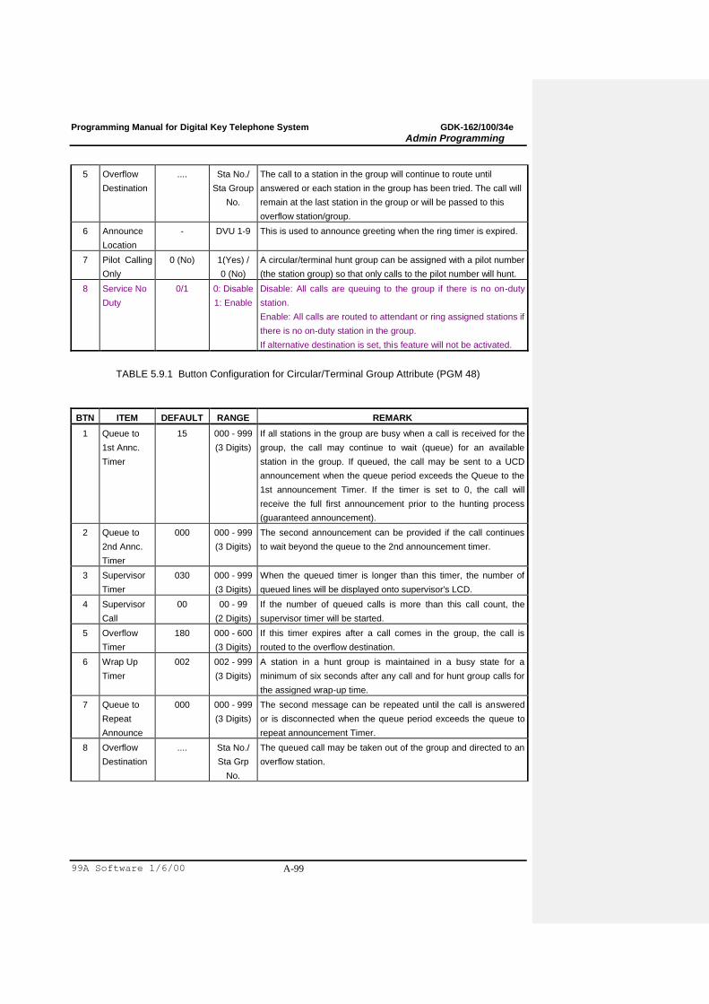
Programming Manual for Digital Key Telephone System GDK-162/100/34e
Admin Programming
99A Software 1/6/00 A-99
5 Overflow
Destination
.... Sta No./
Sta Group
No.
The call to a station in the group will continue to route until
answered or each station in the group has been tried. The call will
remain at the last station in the group or will be passed to this
overflow station/group.
6 Announce
Location
- DVU 1-9 This is used to announce greeting when the ring timer is expired.
7 Pilot Calling
Only
0 (No) 1(Yes) /
0 (No)
A circular/terminal hunt group can be assigned with a pilot number
(the station group) so that only calls to the pilot number will hunt.
8 Service No
Duty
0/1 0: Disable
1: Enable
Disable: All calls are queuing to the group if there is no on-duty
station.
Enable: All calls are routed to attendant or ring assigned stations if
there is no on-duty station in the group.
If alternative destination is set, this feature will not be activated.
TABLE 5.9.1 Button Configuration for Circular/Terminal Group Attribute (PGM 48)
BTN ITEM DEFAULT RANGE REMARK
1 Queue to
1st Annc.
Timer
15 000 - 999
(3 Digits)
If all stations in the group are busy when a call is received for the
group, the call may continue to wait (queue) for an available
station in the group. If queued, the call may be sent to a UCD
announcement when the queue period exceeds the Queue to the
1st announcement Timer. If the timer is set to 0, the call will
receive the full first announcement prior to the hunting process
(guaranteed announcement).
2 Queue to
2nd Annc.
Timer
000 000 - 999
(3 Digits)
The second announcement can be provided if the call continues
to wait beyond the queue to the 2nd announcement timer.
3 Supervisor
Timer
030 000 - 999
(3 Digits)
When the queued timer is longer than this timer, the number of
queued lines will be displayed onto supervisor's LCD.
4 Supervisor
Call
00
00 - 99
(2 Digits)
If the number of queued calls is more than this call count, the
supervisor timer will be started.
5 Overflow
Timer
180 000 - 600
(3 Digits)
If this timer expires after a call comes in the group, the call is
routed to the overflow destination.
6 Wrap Up
Timer
002 002 - 999
(3 Digits)
A station in a hunt group is maintained in a busy state for a
minimum of six seconds after any call and for hunt group calls for
the assigned wrap-up time.
7 Queue to
Repeat
Announce
000 000 - 999
(3 Digits)
The second message can be repeated until the call is answered
or is disconnected when the queue period exceeds the queue to
repeat announcement Timer.
8 Overflow
Destination
.... Sta No./
Sta Grp
No.
The queued call may be taken out of the group and directed to an
overflow station.
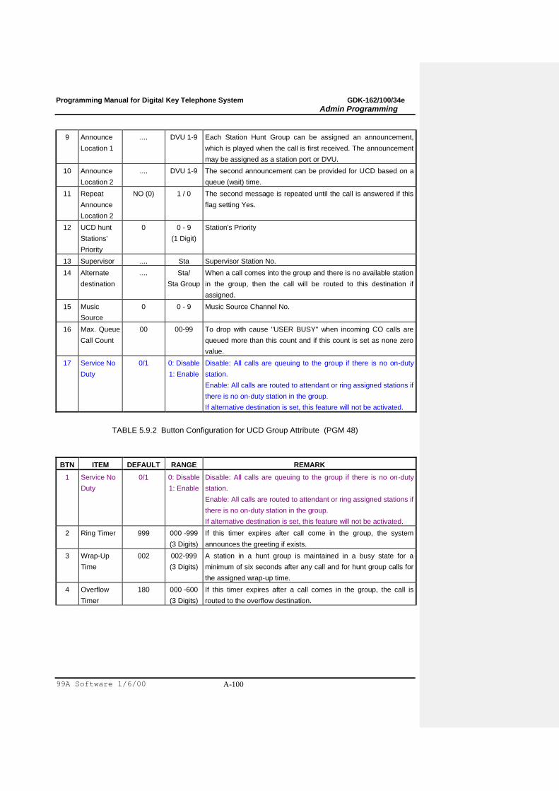
Programming Manual for Digital Key Telephone System GDK-162/100/34e
Admin Programming
99A Software 1/6/00 A-100
9 Announce
Location 1
.... DVU 1-9 Each Station Hunt Group can be assigned an announcement,
which is played when the call is first received. The announcement
may be assigned as a station port or DVU.
10 Announce
Location 2
.... DVU 1-9 The second announcement can be provided for UCD based on a
queue (wait) time.
11 Repeat
Announce
Location 2
NO (0) 1 / 0 The second message is repeated until the call is answered if this
flag setting Yes.
12 UCD hunt
Stations'
Priority
0 0 - 9
(1 Digit)
Station's Priority
13 Supervisor .... Sta Supervisor Station No.
14 Alternate
destination
.... Sta/
Sta Group
When a call comes into the group and there is no available station
in the group, then the call will be routed to this destination if
assigned.
15 Music
Source
0 0 - 9 Music Source Channel No.
16 Max. Queue
Call Count
00 00-99 To drop with cause "USER BUSY" when incoming CO calls are
queued more than this count and if this count is set as none zero
value.
17 Service No
Duty
0/1 0: Disable
1: Enable
Disable: All calls are queuing to the group if there is no on-duty
station.
Enable: All calls are routed to attendant or ring assigned stations if
there is no on-duty station in the group.
If alternative destination is set, this feature will not be activated.
TABLE 5.9.2 Button Configuration for UCD Group Attribute (PGM 48)
BTN ITEM DEFAULT RANGE REMARK
1 Service No
Duty
0/1 0: Disable
1: Enable
Disable: All calls are queuing to the group if there is no on-duty
station.
Enable: All calls are routed to attendant or ring assigned stations if
there is no on-duty station in the group.
If alternative destination is set, this feature will not be activated.
2 Ring Timer 999 000 -999
(3 Digits)
If this timer expires after call come in the group, the system
announces the greeting if exists.
3 Wrap-Up
Time
002 002-999
(3 Digits)
A station in a hunt group is maintained in a busy state for a
minimum of six seconds after any call and for hunt group calls for
the assigned wrap-up time.
4 Overflow
Timer
180 000 -600
(3 Digits)
If this timer expires after a call comes in the group, the call is
routed to the overflow destination.
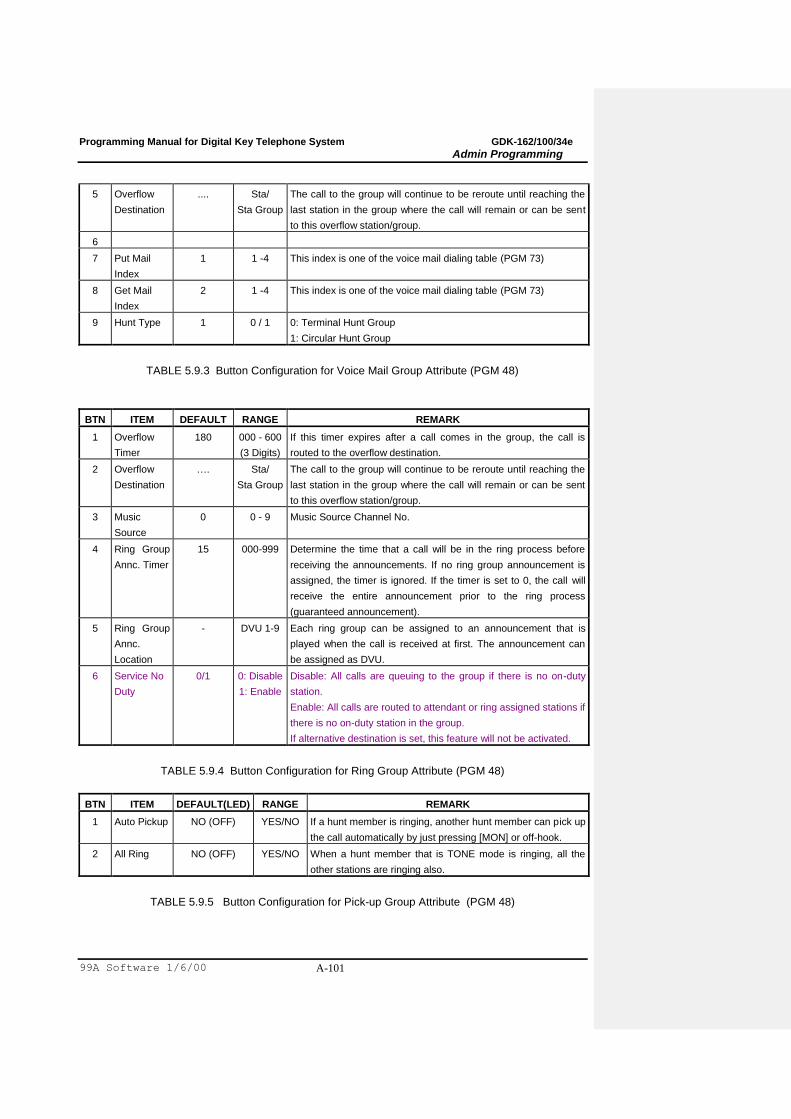
Programming Manual for Digital Key Telephone System GDK-162/100/34e
Admin Programming
99A Software 1/6/00 A-101
5 Overflow
Destination
.... Sta/
Sta Group
The call to the group will continue to be reroute until reaching the
last station in the group where the call will remain or can be sent
to this overflow station/group.
6
7 Put Mail
Index
1 1 -4 This index is one of the voice mail dialing table (PGM 73)
8 Get Mail
Index
2 1 -4 This index is one of the voice mail dialing table (PGM 73)
9 Hunt Type 1 0 / 1 0: Terminal Hunt Group
1: Circular Hunt Group
TABLE 5.9.3 Button Configuration for Voice Mail Group Attribute (PGM 48)
BTN ITEM DEFAULT RANGE REMARK
1 Overflow
Timer
180 000 - 600
(3 Digits)
If this timer expires after a call comes in the group, the call is
routed to the overflow destination.
2 Overflow
Destination
…. Sta/
Sta Group
The call to the group will continue to be reroute until reaching the
last station in the group where the call will remain or can be sent
to this overflow station/group.
3 Music
Source
0 0 - 9 Music Source Channel No.
4 Ring Group
Annc. Timer
15 000-999 Determine the time that a call will be in the ring process before
receiving the announcements. If no ring group announcement is
assigned, the timer is ignored. If the timer is set to 0, the call will
receive the entire announcement prior to the ring process
(guaranteed announcement).
5 Ring Group
Annc.
Location
- DVU 1-9 Each ring group can be assigned to an announcement that is
played when the call is received at first. The announcement can
be assigned as DVU.
6 Service No
Duty
0/1 0: Disable
1: Enable
Disable: All calls are queuing to the group if there is no on-duty
station.
Enable: All calls are routed to attendant or ring assigned stations if
there is no on-duty station in the group.
If alternative destination is set, this feature will not be activated.
TABLE 5.9.4 Button Configuration for Ring Group Attribute (PGM 48)
BTN ITEM DEFAULT(LED) RANGE REMARK
1 Auto Pickup NO (OFF) YES/NO If a hunt member is ringing, another hunt member can pick up
the call automatically by just pressing [MON] or off-hook.
2 All Ring NO (OFF) YES/NO When a hunt member that is TONE mode is ringing, all the
other stations are ringing also.
TABLE 5.9.5 Button Configuration for Pick-up Group Attribute (PGM 48)
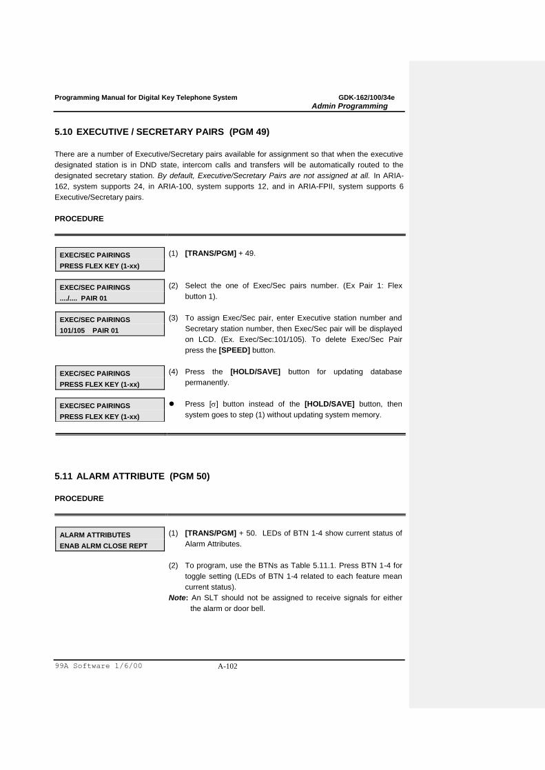
Programming Manual for Digital Key Telephone System GDK-162/100/34e
Admin Programming
99A Software 1/6/00 A-102
5.10 EXECUTIVE / SECRETARY PAIRS (PGM 49)
There are a number of Executive/Secretary pairs available for assignment so that when the executive
designated station is in DND state, intercom calls and transfers will be automatically routed to the
designated secretary station. By default, Executive/Secretary Pairs are not assigned at all. In ARIA-
162, system supports 24, in ARIA-100, system supports 12, and in ARIA-FPII, system supports 6
Executive/Secretary pairs.
PROCEDURE
EXEC/SEC PAIRINGS
PRESS FLEX KEY (1-xx)
(1) [TRANS/PGM] + 49.
EXEC/SEC PAIRINGS
..../.... PAIR 01
(2) Select the one of Exec/Sec pairs number. (Ex Pair 1: Flex
button 1).
EXEC/SEC PAIRINGS
101/105 PAIR 01
(3) To assign Exec/Sec pair, enter Executive station number and
Secretary station number, then Exec/Sec pair will be displayed
on LCD. (Ex. Exec/Sec:101/105). To delete Exec/Sec Pair
press the [SPEED] button.
EXEC/SEC PAIRINGS
PRESS FLEX KEY (1-xx)
(4) Press the [HOLD/SAVE] button for updating database
permanently.
EXEC/SEC PAIRINGS
PRESS FLEX KEY (1-xx)
Press [] button instead of the [HOLD/SAVE] button, then
system goes to step (1) without updating system memory.
5.11 ALARM ATTRIBUTE (PGM 50)
PROCEDURE
ALARM ATTRIBUTES
ENAB ALRM CLOSE REPT
(1) [TRANS/PGM] + 50. LEDs of BTN 1-4 show current status of
Alarm Attributes.
(2) To program, use the BTNs as Table 5.11.1. Press BTN 1-4 for
toggle setting (LEDs of BTN 1-4 related to each feature mean
current status).
Note: An SLT should not be assigned to receive signals for either
the alarm or door bell.
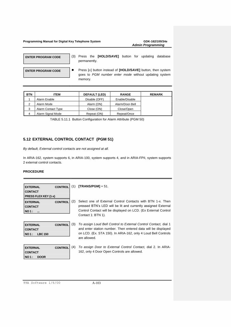
Programming Manual for Digital Key Telephone System GDK-162/100/34e
Admin Programming
99A Software 1/6/00 A-103
ENTER PROGRAM CODE
(3) Press the [HOLD/SAVE] button for updating database
permanently.
ENTER PROGRAM CODE
Press [] button instead of [HOLD/SAVE] button, then system
goes to PGM number enter mode without updating system
memory.
BTN ITEM DEFAULT (LED) RANGE REMARK
1 Alarm Enable Disable (OFF) Enable/Disable
2 Alarm Mode Alarm (ON) Alarm/Door-Bell
3 Alarm Contact Type Close (ON) Close/Open
4 Alarm Signal Mode Repeat (ON) Repeat/Once
TABLE 5.11.1 Button Configuration for Alarm Attribute (PGM 50)
5.12 EXTERNAL CONTROL CONTACT (PGM 51)
By default, External control contacts are not assigned at all.
In ARIA-162, system supports 6, in ARIA-100, system supports 4, and in ARIA-FPII, system supports
2 external control contacts.
PROCEDURE
EXTERNAL CONTROL
CONTACT
PRESS FLEX KEY (1-x)
(1) [TRANS/PGM] + 51.
EXTERNAL CONTROL
CONTACT
NO 1 : ...
(2) Select one of External Control Contacts with BTN 1-x. Then
pressed BTN‟s LED will be lit and currently assigned External
Control Contact will be displayed on LCD. (Ex External Control
Contact 1: BTN 1).
EXTERNAL CONTROL
CONTACT
NO 1 : LBC 150
(3) To assign Loud Bell Control to External Control Contact, dial 1
and enter station number. Then entered data will be displayed
on LCD. (Ex. STA 150). In ARIA-162, only 4 Loud Bell Controls
are allowed.
EXTERNAL CONTROL
CONTACT
NO 1 : DOOR
(4) To assign Door to External Control Contact, dial 2. In ARIA-
162, only 4 Door Open Controls are allowed.
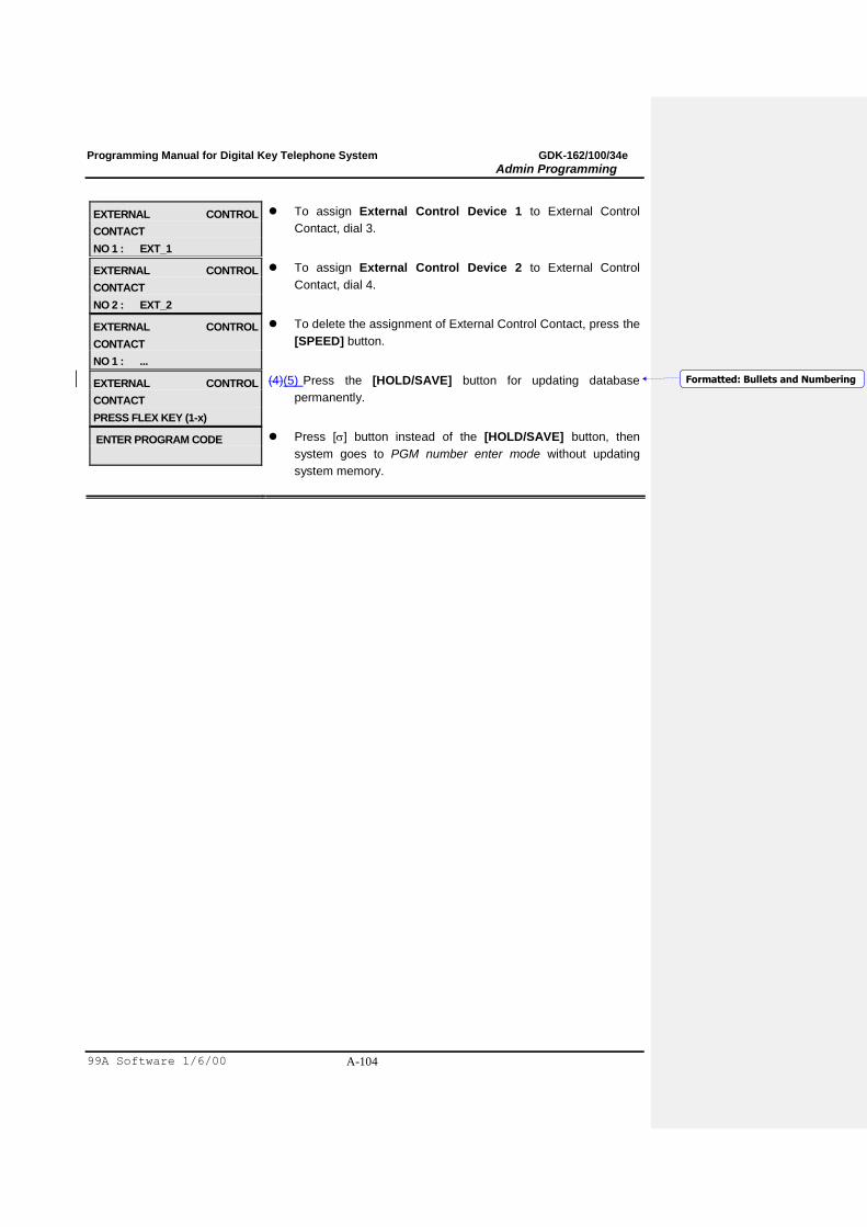
Programming Manual for Digital Key Telephone System GDK-162/100/34e
Admin Programming
99A Software 1/6/00 A-104
EXTERNAL CONTROL
CONTACT
NO 1 : EXT_1
To assign External Control Device 1 to External Control
Contact, dial 3.
EXTERNAL CONTROL
CONTACT
NO 2 : EXT_2
To assign External Control Device 2 to External Control
Contact, dial 4.
EXTERNAL CONTROL
CONTACT
NO 1 : ...
To delete the assignment of External Control Contact, press the
[SPEED] button.
EXTERNAL CONTROL
CONTACT
PRESS FLEX KEY (1-x)
(4)(5) Press the [HOLD/SAVE] button for updating database
permanently.
ENTER PROGRAM CODE
Press [] button instead of the [HOLD/SAVE] button, then
system goes to PGM number enter mode without updating
system memory.
Formatted: Bullets and Numbering

Programming Manual for Digital Key Telephone System GDK-162/100/34e
Admin Programming
99A Software 1/6/00 A-105
5.13 PABX ACCESS CODES (PGM 52)
Maximum 5 PABX Access Codes are assignable. PABX Access Code is 1 or 2-digit number. By
default, PABX Access Codes are not assigned at all.
PROCEDURE
PABX ACCESS CODE
.. .. .. .. ..
(1) [TRANS/PGM] + 52. LCD shows currently assigned PABX
Access codes.
PABX ACCESS CODE
9 .. .. .. ..
(2) To assign PABX Access code, press BTN 1-5 and do one of
followings:
Dial 2 digits number to assign PBX Access Code.
Dial 1 digit number and press the [SPEED] button to assign
1 digit PABX Access Code.
(Ex. Press Flex button 1, dial 9, and press the [SPEED]
button)
Press the [SPEED] button to delete PBX Access Code.
ENTER PROGRAM CODE
(3) Press the [HOLD/SAVE] button for updating database
permanently.
ENTER PROGRAM CODE
Press [] button instead of the [HOLD/SAVE] button, then
system goes to PGM number enter mode without updating
system memory.
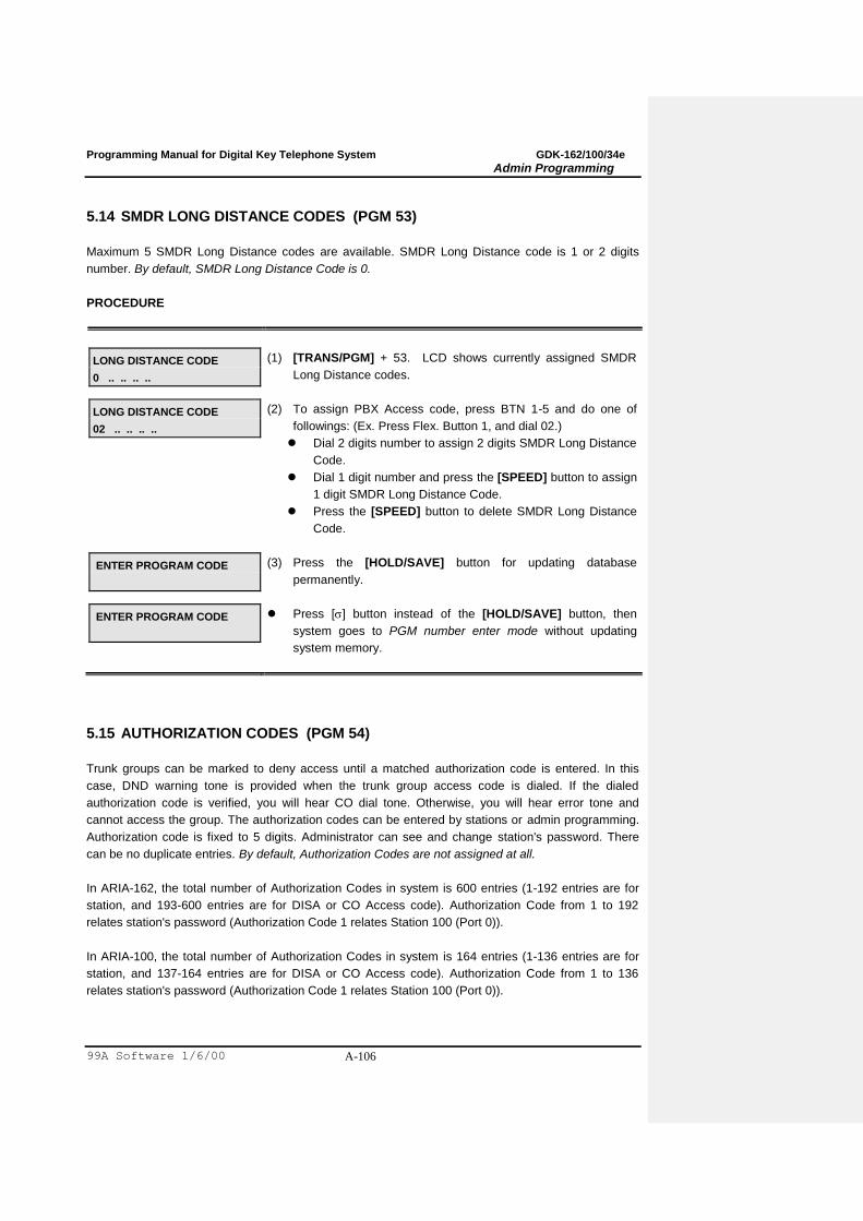
Programming Manual for Digital Key Telephone System GDK-162/100/34e
Admin Programming
99A Software 1/6/00 A-106
5.14 SMDR LONG DISTANCE CODES (PGM 53)
Maximum 5 SMDR Long Distance codes are available. SMDR Long Distance code is 1 or 2 digits
number. By default, SMDR Long Distance Code is 0.
PROCEDURE
LONG DISTANCE CODE
0 .. .. .. ..
(1) [TRANS/PGM] + 53. LCD shows currently assigned SMDR
Long Distance codes.
LONG DISTANCE CODE
02 .. .. .. ..
(2) To assign PBX Access code, press BTN 1-5 and do one of
followings: (Ex. Press Flex. Button 1, and dial 02.)
Dial 2 digits number to assign 2 digits SMDR Long Distance
Code.
Dial 1 digit number and press the [SPEED] button to assign
1 digit SMDR Long Distance Code.
Press the [SPEED] button to delete SMDR Long Distance
Code.
ENTER PROGRAM CODE
(3) Press the [HOLD/SAVE] button for updating database
permanently.
ENTER PROGRAM CODE
Press [] button instead of the [HOLD/SAVE] button, then
system goes to PGM number enter mode without updating
system memory.
5.15 AUTHORIZATION CODES (PGM 54)
Trunk groups can be marked to deny access until a matched authorization code is entered. In this
case, DND warning tone is provided when the trunk group access code is dialed. If the dialed
authorization code is verified, you will hear CO dial tone. Otherwise, you will hear error tone and
cannot access the group. The authorization codes can be entered by stations or admin programming.
Authorization code is fixed to 5 digits. Administrator can see and change station's password. There
can be no duplicate entries. By default, Authorization Codes are not assigned at all.
In ARIA-162, the total number of Authorization Codes in system is 600 entries (1-192 entries are for
station, and 193-600 entries are for DISA or CO Access code). Authorization Code from 1 to 192
relates station's password (Authorization Code 1 relates Station 100 (Port 0)).
In ARIA-100, the total number of Authorization Codes in system is 164 entries (1-136 entries are for
station, and 137-164 entries are for DISA or CO Access code). Authorization Code from 1 to 136
relates station's password (Authorization Code 1 relates Station 100 (Port 0)).
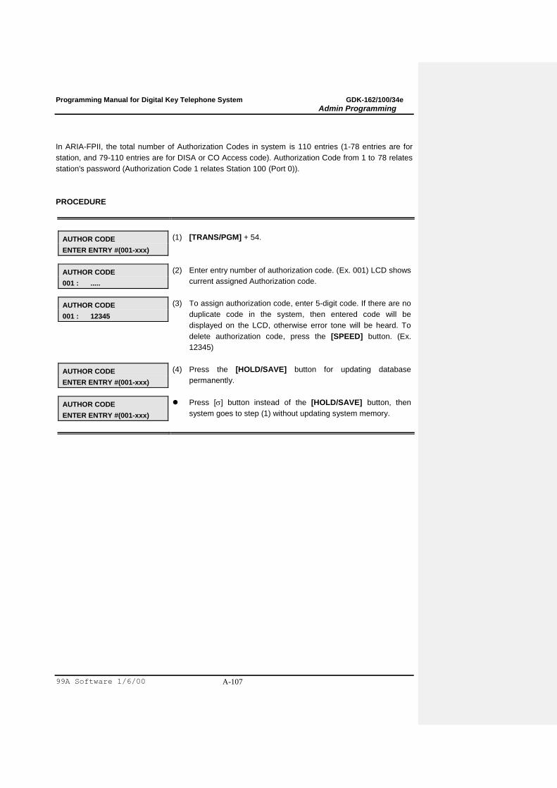
Programming Manual for Digital Key Telephone System GDK-162/100/34e
Admin Programming
99A Software 1/6/00 A-107
In ARIA-FPII, the total number of Authorization Codes in system is 110 entries (1-78 entries are for
station, and 79-110 entries are for DISA or CO Access code). Authorization Code from 1 to 78 relates
station's password (Authorization Code 1 relates Station 100 (Port 0)).
PROCEDURE
AUTHOR CODE
ENTER ENTRY #(001-xxx)
(1) [TRANS/PGM] + 54.
AUTHOR CODE
001 : .....
(2) Enter entry number of authorization code. (Ex. 001) LCD shows
current assigned Authorization code.
AUTHOR CODE
001 : 12345
(3) To assign authorization code, enter 5-digit code. If there are no
duplicate code in the system, then entered code will be
displayed on the LCD, otherwise error tone will be heard. To
delete authorization code, press the [SPEED] button. (Ex.
12345)
AUTHOR CODE
ENTER ENTRY #(001-xxx)
(4) Press the [HOLD/SAVE] button for updating database
permanently.
AUTHOR CODE
ENTER ENTRY #(001-xxx)
Press [] button instead of the [HOLD/SAVE] button, then
system goes to step (1) without updating system memory.
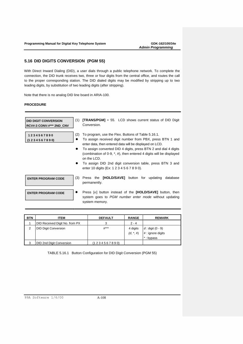
Programming Manual for Digital Key Telephone System GDK-162/100/34e
Admin Programming
99A Software 1/6/00 A-108
5.16 DID DIGITS CONVERSION (PGM 55)
With Direct Inward Dialing (DID), a user dials through a public telephone network. To complete the
connection, the DID trunk receives two, three or four digits from the central office, and routes the call
to the proper corresponding station. The DID dialed digits may be modified by stripping up to two
leading digits, by substitution of two leading digits (after stripping).
Note that there is no analog DID line board in ARIA-100.
PROCEDURE
DID DIGIT CONVERSION
RCV#:3 CONV:#*** 2ND_CNV
(1) [TRANS/PGM] + 55. LCD shows current status of DID Digit
Conversion.
1 2 3 4 5 6 7 8 9 0
(1 2 3 4 5 6 7 8 9 0)
(2) To program, use the Flex. Buttons of Table 5.16.1.
To assign received digit number from PBX, press BTN 1 and
enter data, then entered data will be displayed on LCD.
To assign converted DID 4 digits, press BTN 2 and dial 4 digits
(combination of 0-9, *, #), then entered 4 digits will be displayed
on the LCD.
To assign DID 2nd digit conversion table, press BTN 3 and
enter 10 digits (Ex: 1 2 3 4 5 6 7 8 9 0).
ENTER PROGRAM CODE
(3) Press the [HOLD/SAVE] button for updating database
permanently.
ENTER PROGRAM CODE
Press [] button instead of the [HOLD/SAVE] button, then
system goes to PGM number enter mode without updating
system memory.
BTN ITEM DEFAULT RANGE REMARK
1 DID Received Digit No. from PX 3 2 - 4
2 DID Digit Conversion #*** 4 digits
(d, *, #)
d : digit (0 - 9)
# : ignore digits
* : bypass
3 DID 2nd Digit Conversion (1 2 3 4 5 6 7 8 9 0)
TABLE 5.16.1 Button Configuration for DID Digit Conversion (PGM 55)
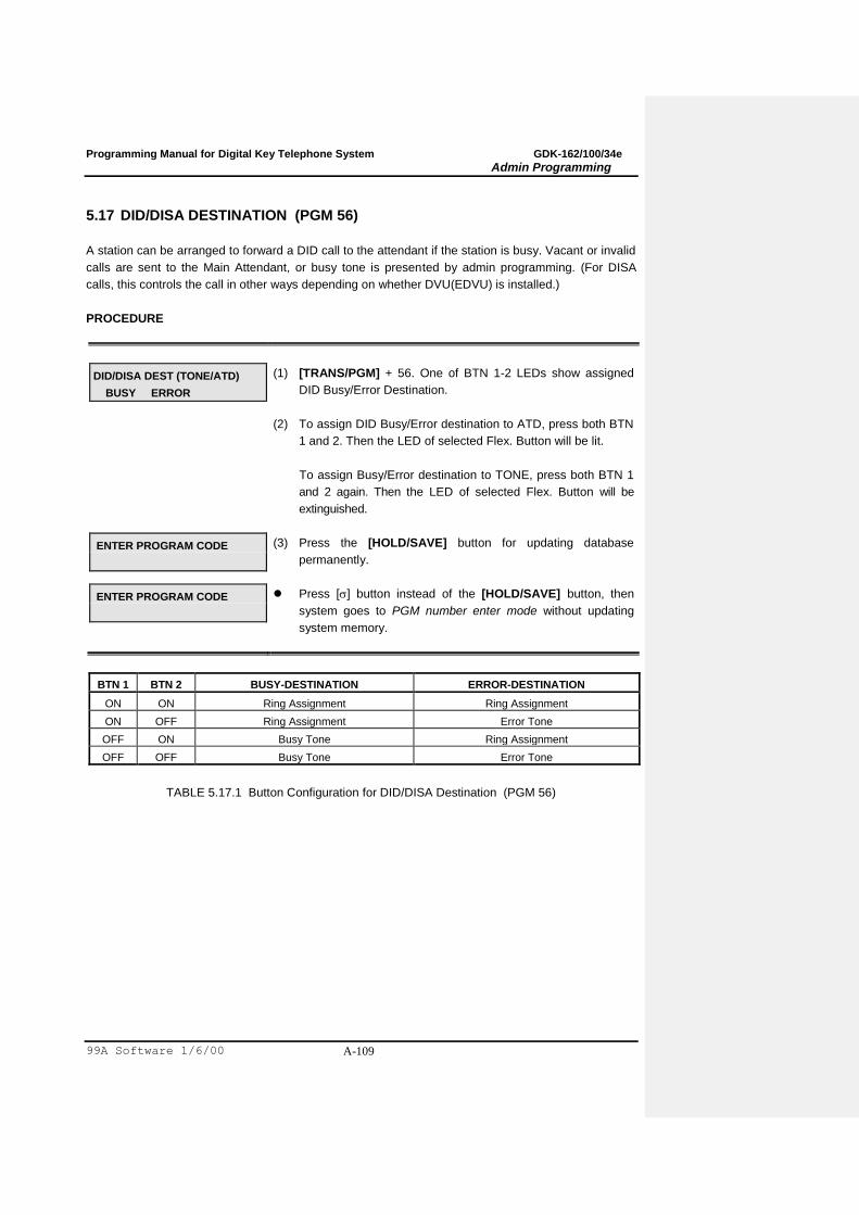
Programming Manual for Digital Key Telephone System GDK-162/100/34e
Admin Programming
99A Software 1/6/00 A-109
5.17 DID/DISA DESTINATION (PGM 56)
A station can be arranged to forward a DID call to the attendant if the station is busy. Vacant or invalid
calls are sent to the Main Attendant, or busy tone is presented by admin programming. (For DISA
calls, this controls the call in other ways depending on whether DVU(EDVU) is installed.)
PROCEDURE
DID/DISA DEST (TONE/ATD)
BUSY ERROR
(1) [TRANS/PGM] + 56. One of BTN 1-2 LEDs show assigned
DID Busy/Error Destination.
(2) To assign DID Busy/Error destination to ATD, press both BTN
1 and 2. Then the LED of selected Flex. Button will be lit.
To assign Busy/Error destination to TONE, press both BTN 1
and 2 again. Then the LED of selected Flex. Button will be
extinguished.
ENTER PROGRAM CODE
(3) Press the [HOLD/SAVE] button for updating database
permanently.
ENTER PROGRAM CODE
Press [] button instead of the [HOLD/SAVE] button, then
system goes to PGM number enter mode without updating
system memory.
BTN 1 BTN 2 BUSY-DESTINATION ERROR-DESTINATION
ON ON Ring Assignment Ring Assignment
ON OFF Ring Assignment Error Tone
OFF ON Busy Tone Ring Assignment
OFF OFF Busy Tone Error Tone
TABLE 5.17.1 Button Configuration for DID/DISA Destination (PGM 56)
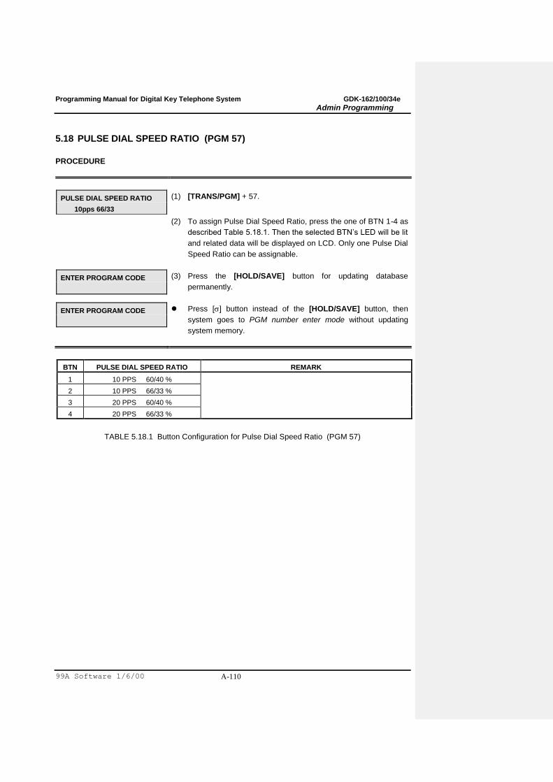
Programming Manual for Digital Key Telephone System GDK-162/100/34e
Admin Programming
99A Software 1/6/00 A-110
5.18 PULSE DIAL SPEED RATIO (PGM 57)
PROCEDURE
PULSE DIAL SPEED RATIO
10pps 66/33
(1) [TRANS/PGM] + 57.
(2) To assign Pulse Dial Speed Ratio, press the one of BTN 1-4 as
described Table 5.18.1. Then the selected BTN‟s LED will be lit
and related data will be displayed on LCD. Only one Pulse Dial
Speed Ratio can be assignable.
ENTER PROGRAM CODE
(3) Press the [HOLD/SAVE] button for updating database
permanently.
ENTER PROGRAM CODE
Press [] button instead of the [HOLD/SAVE] button, then
system goes to PGM number enter mode without updating
system memory.
BTN PULSE DIAL SPEED RATIO REMARK
1 10 PPS 60/40 %
2 10 PPS 66/33 %
3 20 PPS 60/40 %
4 20 PPS 66/33 %
TABLE 5.18.1 Button Configuration for Pulse Dial Speed Ratio (PGM 57)
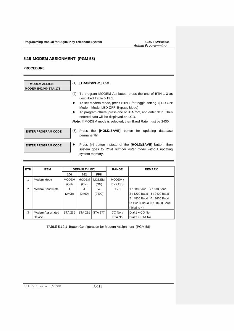
Programming Manual for Digital Key Telephone System GDK-162/100/34e
Admin Programming
99A Software 1/6/00 A-111
5.19 MODEM ASSIGNMENT (PGM 58)
PROCEDURE
MODEM ASSIGN
MODEM B02400 STA:171
(1) [TRANS/PGM] + 58.
(2) To program MODEM Attributes, press the one of BTN 1-3 as
described Table 5.19.1.
To set Modem mode, press BTN 1 for toggle setting. (LED ON:
Modem Mode, LED OFF: Bypass Mode)
To program others, press one of BTN 2-3, and enter data. Then
entered data will be displayed on LCD.
Note: If MODEM mode is selected, then Baud Rate must be 2400.
ENTER PROGRAM CODE
(3) Press the [HOLD/SAVE] button for updating database
permanently.
ENTER PROGRAM CODE
Press [] button instead of the [HOLD/SAVE] button, then
system goes to PGM number enter mode without updating
system memory.
BTN ITEM DEFAULT (LED) RANGE REMARK
100 162 FPII
1 Modem Mode MODEM
(ON)
MODEM
(ON)
MODEM
(ON)
MODEM /
BYPASS
2 Modem Baud Rate 4
(2400)
4
(2400)
4
(2400)
1 - 8 1 : 300 Baud 2 : 600 Baud
3 : 1200 Baud 4 : 2400 Baud
5 : 4800 Baud 6 : 9600 Baud
6: 19200 Baud 8 : 38400 Baud
(fixed to 4)
3 Modem Associated
Device
STA 235 STA 291 STA 177 CO No. /
STA No
Dial 1 + CO No.
Dial 2 + STA No.
TABLE 5.19.1 Button Configuration for Modem Assignment (PGM 58)
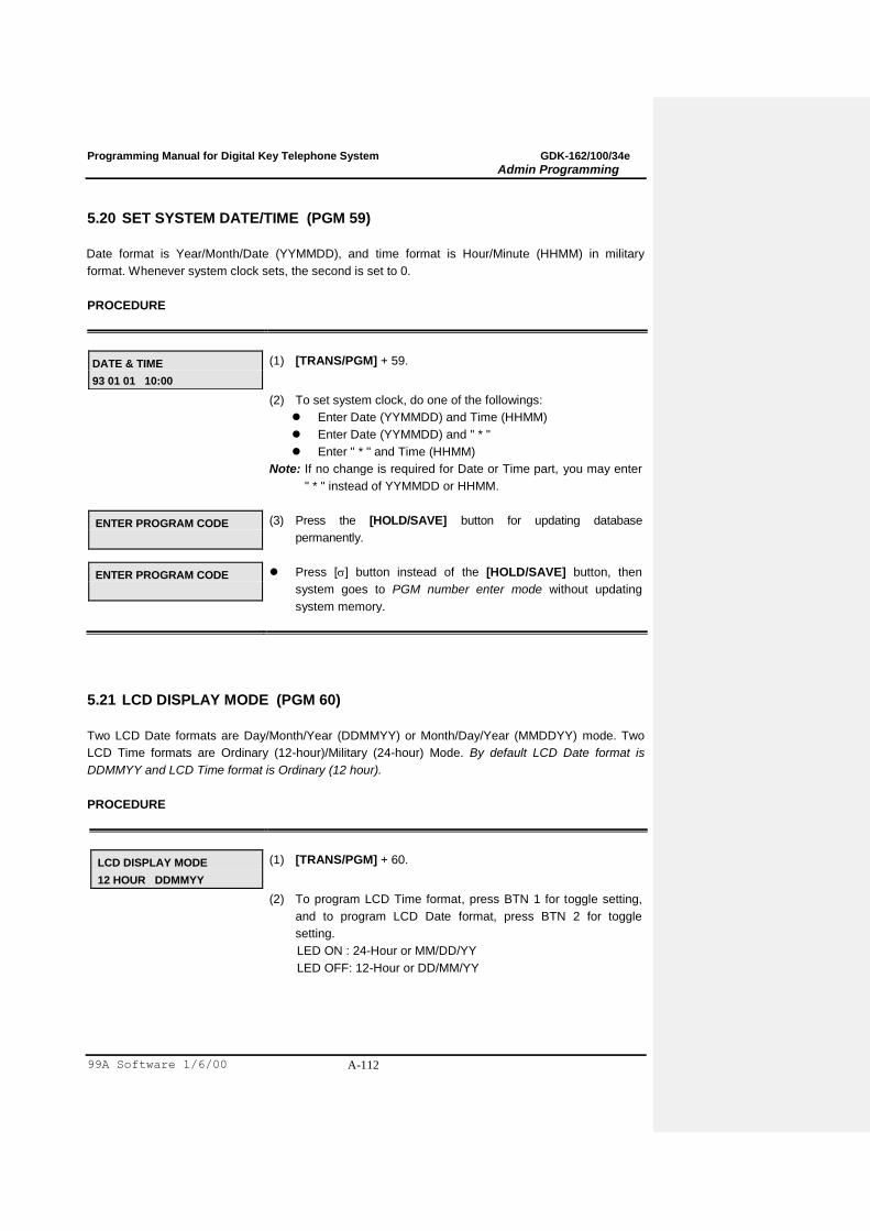
Programming Manual for Digital Key Telephone System GDK-162/100/34e
Admin Programming
99A Software 1/6/00 A-112
5.20 SET SYSTEM DATE/TIME (PGM 59)
Date format is Year/Month/Date (YYMMDD), and time format is Hour/Minute (HHMM) in military
format. Whenever system clock sets, the second is set to 0.
PROCEDURE
DATE & TIME
93 01 01 10:00
(1) [TRANS/PGM] + 59.
(2) To set system clock, do one of the followings:
Enter Date (YYMMDD) and Time (HHMM)
Enter Date (YYMMDD) and " * "
Enter " * " and Time (HHMM)
Note: If no change is required for Date or Time part, you may enter
" * " instead of YYMMDD or HHMM.
ENTER PROGRAM CODE
(3) Press the [HOLD/SAVE] button for updating database
permanently.
ENTER PROGRAM CODE
Press [] button instead of the [HOLD/SAVE] button, then
system goes to PGM number enter mode without updating
system memory.
5.21 LCD DISPLAY MODE (PGM 60)
Two LCD Date formats are Day/Month/Year (DDMMYY) or Month/Day/Year (MMDDYY) mode. Two
LCD Time formats are Ordinary (12-hour)/Military (24-hour) Mode. By default LCD Date format is
DDMMYY and LCD Time format is Ordinary (12 hour).
PROCEDURE
LCD DISPLAY MODE
12 HOUR DDMMYY
(1) [TRANS/PGM] + 60.
(2) To program LCD Time format, press BTN 1 for toggle setting,
and to program LCD Date format, press BTN 2 for toggle
setting.
LED ON : 24-Hour or MM/DD/YY
LED OFF: 12-Hour or DD/MM/YY
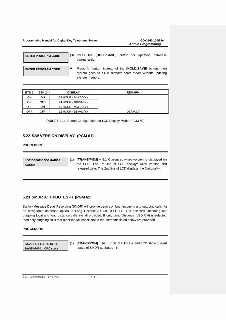
Programming Manual for Digital Key Telephone System GDK-162/100/34e
Admin Programming
99A Software 1/6/00 A-113
ENTER PROGRAM CODE
(3) Press the [HOLD/SAVE] button for updating database
permanently.
ENTER PROGRAM CODE
Press [] button instead of the [HOLD/SAVE] button, then
system goes to PGM number enter mode without updating
system memory.
BTN 1 BTN 2 DISPLAY REMARK
ON ON 24 HOUR - MM/DD/YY
ON OFF 24 HOUR - DD/MM/YY
OFF ON 12 HOUR - MM/DD/YY
OFF OFF 12 HOUR - DD/MM/YY DEFAULT
TABLE 5.21.1 Button Configuration for LCD Display Mode (PGM 60)
5.22 S/W VERSION DISPLAY (PGM 61)
PROCEDURE
LGE/GS86P-5.5Df MAR/00
KOREA
(1) [TRANS/PGM] + 61. Current software version is displayed on
the LCD. The 1st line of LCD displays MPB version and
released date. The 2nd line of LCD displays the Nationality.
5.23 SMDR ATTRIBUTES - I (PGM 62)
Station Message Detail Recording (SMDR) will provide details on both incoming and outgoing calls. As
an assignable database option, if Long Distance/All Call (LED OFF) is selected, incoming and
outgoing local and long distance calls are all provided. If only Long Distance (LED ON) is selected,
then only outgoing calls that meet the toll check status requirements listed below are provided.
PROCEDURE
SAVE PRT LD PIC DETL
BAUD09600 CRCY:xxx
(1) [TRANS/PGM] + 62. LEDs of BTN 1-7 and LCD show current
status of SMDR attributes - I.

Programming Manual for Digital Key Telephone System GDK-162/100/34e
Admin Programming
99A Software 1/6/00 A-114
(2) To program SMDR attributes - I, use the BTNs as Table 5.23.2.
Press BTN 1-5 for toggle setting. (LEDs of BTN 1-5 related to
each feature mean current status)
To program SMDR print baud rate, press BTN 6 and dial one of
1 - 8.
1 - Baud 300 / 2 - Baud 600 / 3 - Baud 1200 / 4 - Baud 2400
5 - Baud 4800 / 6 - Baud 9600 / 7 - Baud 19200 / 8 - Baud 38400
To assign Currency Unit, press BTN 7 and dial 6 digits (3
letters). The letters of the Currency Unit are entered as Table
5.23.1.
ENTER PROGRAM CODE
(3) Press the [HOLD/SAVE] button for updating database
permanently.
ENTER PROGRAM CODE
Press [] button instead of the [HOLD/SAVE] button, then
system goes to PGM number enter mode without updating
system memory.
. – 13 1 – 10
A - 21 B - 22 C - 23 2 - 20
D - 31 E - 32 F - 33 3 - 30
G - 41 H - 42 I - 43 4 - 40
J - 51 K - 52 L - 53 5 - 50
M - 61 N - 62 O - 63 6 - 60
P - 71 R - 72 S - 73 Q - 7* 7 - 70
T - 81 U - 82 V - 83 8 - 80
W - 91 X - 92 Y - 93 Z - 9# 9 - 90
*1 - Blank *2 - : *3 - ,
0-00 #
TABLE 5.23.1 English Character Set
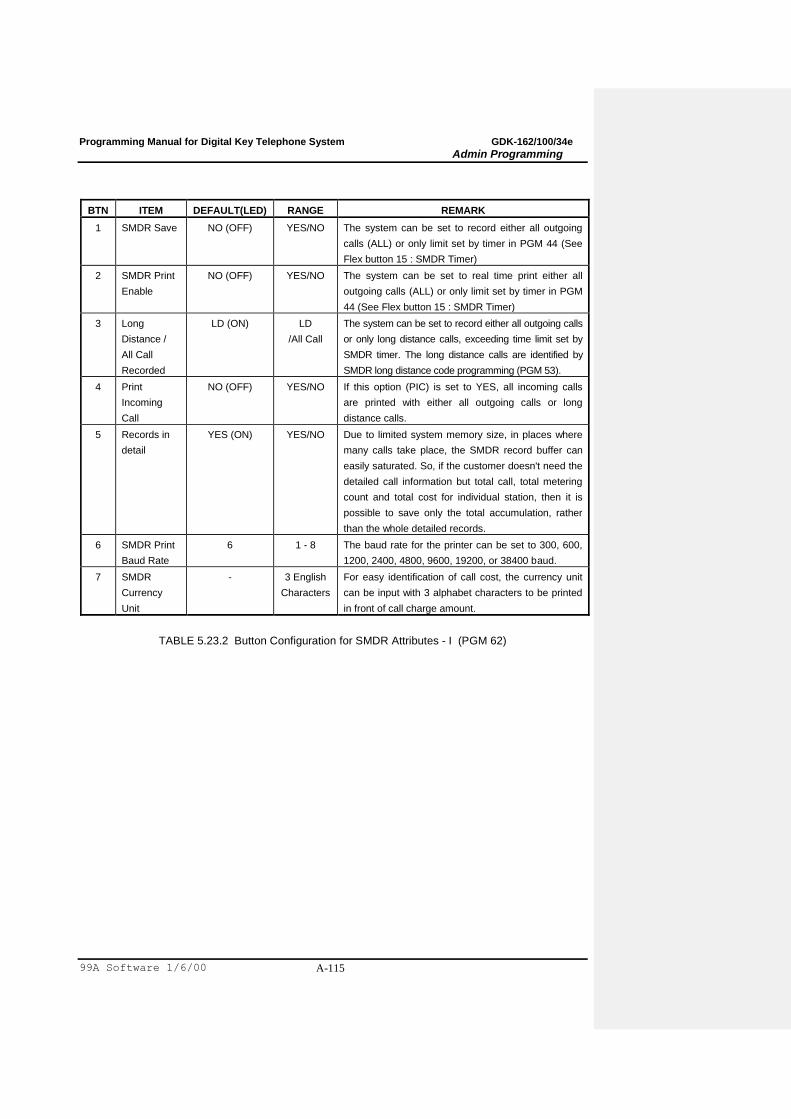
Programming Manual for Digital Key Telephone System GDK-162/100/34e
Admin Programming
99A Software 1/6/00 A-115
BTN ITEM DEFAULT(LED) RANGE REMARK
1 SMDR Save NO (OFF) YES/NO The system can be set to record either all outgoing
calls (ALL) or only limit set by timer in PGM 44 (See
Flex button 15 : SMDR Timer)
2 SMDR Print
Enable
NO (OFF) YES/NO The system can be set to real time print either all
outgoing calls (ALL) or only limit set by timer in PGM
44 (See Flex button 15 : SMDR Timer)
3 Long
Distance /
All Call
Recorded
LD (ON) LD
/All Call
The system can be set to record either all outgoing calls
or only long distance calls, exceeding time limit set by
SMDR timer. The long distance calls are identified by
SMDR long distance code programming (PGM 53).
4 Print
Incoming
Call
NO (OFF) YES/NO If this option (PIC) is set to YES, all incoming calls
are printed with either all outgoing calls or long
distance calls.
5 Records in
detail
YES (ON) YES/NO Due to limited system memory size, in places where
many calls take place, the SMDR record buffer can
easily saturated. So, if the customer doesn't need the
detailed call information but total call, total metering
count and total cost for individual station, then it is
possible to save only the total accumulation, rather
than the whole detailed records.
6 SMDR Print
Baud Rate
6
1 - 8
The baud rate for the printer can be set to 300, 600,
1200, 2400, 4800, 9600, 19200, or 38400 baud.
7 SMDR
Currency
Unit
- 3 English
Characters
For easy identification of call cost, the currency unit
can be input with 3 alphabet characters to be printed
in front of call charge amount.
TABLE 5.23.2 Button Configuration for SMDR Attributes - I (PGM 62)
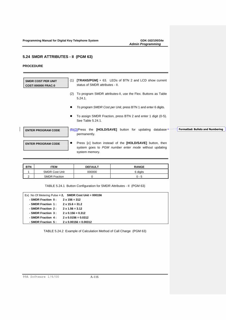
Programming Manual for Digital Key Telephone System GDK-162/100/34e
Admin Programming
99A Software 1/6/00 A-116
5.24 SMDR ATTRIBUTES - II (PGM 63)
PROCEDURE
SMDR COST PER UNIT
COST:000000 FRAC:0
(1) [TRANS/PGM] + 63. LEDs of BTN 2 and LCD show current
status of SMDR attributes - II.
(2) To program SMDR attributes-II, use the Flex. Buttons as Table
5.24.1.
To program SMDR Cost per Unit, press BTN 1 and enter 6 digits.
To assign SMDR Fraction, press BTN 2 and enter 1 digit (0-5).
See Table 5.24.1.
ENTER PROGRAM CODE
(5)(3)Press the [HOLD/SAVE] button for updating database
permanently.
ENTER PROGRAM CODE
Press [] button instead of the [HOLD/SAVE] button, then
system goes to PGM number enter mode without updating
system memory.
BTN ITEM DEFAULT RANGE
1 SMDR Cost Unit 000000 6 digits
2 SMDR Fraction 0 0 - 5
TABLE 5.24.1 Button Configuration for SMDR Attributes - II (PGM 63)
Ex) No Of Metering Pulse = 2, SMDR Cost Unit = 000156
- SMDR Fraction 0 : 2 x 156 = 312
- SMDR Fraction 1 : 2 x 15.6 = 31.2
- SMDR Fraction 2 : 2 x 1.56 = 3.12
- SMDR Fraction 3 : 2 x 0.156 = 0.312
- SMDR Fraction 4 : 2 x 0.0156 = 0.0312
- SMDR Fraction 5 : 2 x 0.00156 = 0.00312
TABLE 5.24.2 Example of Calculation Method of Call Charge (PGM 63)
Formatted: Bullets and Numbering

Programming Manual for Digital Key Telephone System GDK-162/100/34e
Admin Programming
99A Software 1/6/00 A-117
5.25 TIE ROUTING TABLE (PGM 65)
Maximum 30 Tie Line Routings can be programmed. Maximum 6 CO lines are assignable to each
Routing. By default, Tie Line Routings are not assigned at all.
PROCEDURE
TIE LINE ROUTING
DIAL ROUTING NO 01-30
(1) [TRANS/PGM] + 65.
TIE LINE ROUTING
01 : .. .. .. .. .. ..
(2) Enter two digits for routing number (01-30). (Ex. 01)
(3) To assign TIE Line Routing, press BTN 1-6 and enter CO Line
number. See Table 5.25.1.
To delete any of code, press BTN 1 - 6 and press the [SPEED]
button. See Table 5.25.1.
User can press [] button to jump next Tie Line Routing
programming mode.
TIE LINE ROUTING
DIAL ROUTING NO 01-30
(4) Press the [HOLD/SAVE] button for updating database
permanently.
TIE LINE ROUTING
DIAL ROUTING NO 01-30
Press [] button instead of the [HOLD/SAVE] button, then
system goes to Step (1) without updating system memory.
ITEM BTN RANGE DEFAULT REMARK
Tie Routing Table (1-30) 1 - 6 01 - 48
-
TABLE 5.25.1 Tie Routing Table (PGM 65)
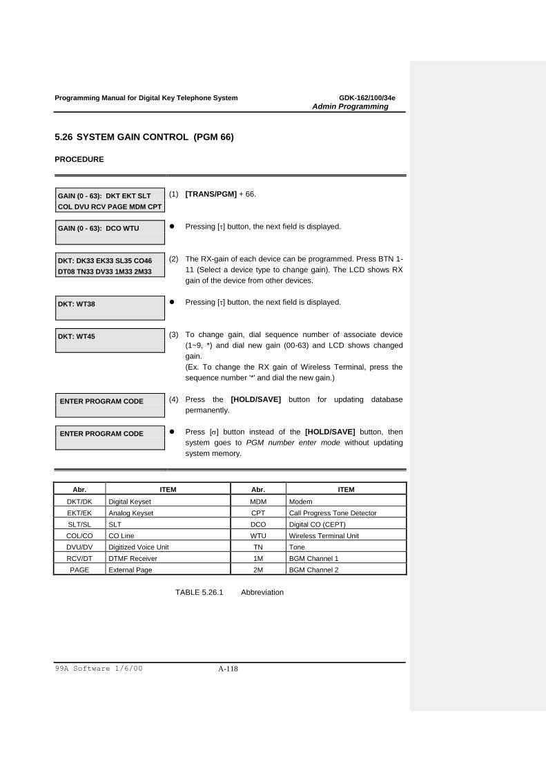
Programming Manual for Digital Key Telephone System GDK-162/100/34e
Admin Programming
99A Software 1/6/00 A-118
5.26 SYSTEM GAIN CONTROL (PGM 66)
PROCEDURE
GAIN (0 - 63): DKT EKT SLT
COL DVU RCV PAGE MDM CPT
(1) [TRANS/PGM] + 66.
GAIN (0 - 63): DCO WTU
Pressing [] button, the next field is displayed.
DKT: DK33 EK33 SL35 CO46
DT08 TN33 DV33 1M33 2M33
(2) The RX-gain of each device can be programmed. Press BTN 1-
11 (Select a device type to change gain). The LCD shows RX
gain of the device from other devices.
DKT: WT38
Pressing [] button, the next field is displayed.
DKT: WT45
(3) To change gain, dial sequence number of associate device
(1~9, *) and dial new gain (00-63) and LCD shows changed
gain.
(Ex. To change the RX gain of Wireless Terminal, press the
sequence number '*' and dial the new gain.)
ENTER PROGRAM CODE
(4) Press the [HOLD/SAVE] button for updating database
permanently.
ENTER PROGRAM CODE
Press [] button instead of the [HOLD/SAVE] button, then
system goes to PGM number enter mode without updating
system memory.
Abr. ITEM Abr. ITEM
DKT/DK Digital Keyset MDM Modem
EKT/EK Analog Keyset CPT Call Progress Tone Detector
SLT/SL SLT DCO Digital CO (CEPT)
COL/CO CO Line WTU Wireless Terminal Unit
DVU/DV Digitized Voice Unit TN Tone
RCV/DT DTMF Receiver 1M BGM Channel 1
PAGE External Page 2M BGM Channel 2
TABLE 5.26.1 Abbreviation
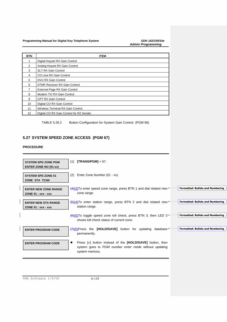
Programming Manual for Digital Key Telephone System GDK-162/100/34e
Admin Programming
99A Software 1/6/00 A-119
BTN ITEM
1 Digital Keyset RX Gain Control
2 Analog Keyset RX Gain Control
3 SLT RX Gain Control
4 CO Line RX Gain Control
5 DVU RX Gain Control
6 DTMF-Receiver RX Gain Control
7 External Page RX Gain Control
8 Modem TX/ RX Gain Control
9 CPT RX Gain Control
10 Digital CO RX Gain Control
11 Wireless Terminal RX Gain Control
12 Digital CO RX Gain Control for R2 Sender
TABLE 5.26.2 Button Configuration for System Gain Control (PGM 66)
5.27 SYSTEM SPEED ZONE ACCESS (PGM 67)
PROCEDURE
SYSTEM SPD ZONE PGM
ENTER ZONE NO (01-xx)
(1) [TRANS/PGM] + 67.
SYSTEM SPD ZONE 01
ZONE STA TCHK
(2) Enter Zone Number (01 - xx).
ENTER NEW ZONE RANGE
ZONE 01 : xxx - xxx
(4)(3)To enter speed zone range, press BTN 1 and dial related new
zone range.
ENTER NEW STA RANGE
ZONE 01 : xxx - xxx
(5)(4)To enter station range, press BTN 2 and dial related new
station range.
(6)(5)To toggle speed zone toll check, press BTN 3, then LED 3
shows toll check status of current zone.
ENTER PROGRAM CODE
(7)(6)Press the [HOLD/SAVE] button for updating database
permanently.
ENTER PROGRAM CODE
Press [] button instead of the [HOLD/SAVE] button, then
system goes to PGM number enter mode without updating
system memory.
Formatted: Bullets and Numbering
Formatted: Bullets and Numbering
Formatted: Bullets and Numbering
Formatted: Bullets and Numbering
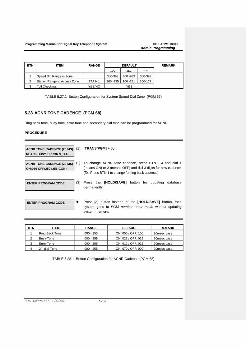
Programming Manual for Digital Key Telephone System GDK-162/100/34e
Admin Programming
99A Software 1/6/00 A-120
BTN ITEM RANGE DEFAULT REMARK
100 162 FPII
1 Speed Bin Range in Zone 300-399 400 -999 300-399
2 Station Range to Access Zone STA No. 100 -235 100 -291 100-177
3 Toll Checking YES/NO YES
TABLE 5.27.1 Button Configuration for System Speed Dial Zone (PGM 67)
5.28 ACNR TONE CADENCE (PGM 68)
Ring back tone, busy tone, error tone and secondary dial tone can be programmed for ACNR.
PROCEDURE
ACNR TONE CADENCE (20 MS)
RBACK BUSY ERROR S_DIAL
(1) [TRANS/PGM] + 68.
ACNR TONE CADENCE (20 MS)
ON:050 OFF:250 (255:CON)
(2) To change ACNR tone cadence, press BTN 1-4 and dial 1
(means ON) or 2 (means OFF) and dial 3 digits for new cadence.
(Ex. Press BTN 1 to change for ring back cadence)
ENTER PROGRAM CODE
(3) Press the [HOLD/SAVE] button for updating database
permanently.
ENTER PROGRAM CODE
Press [] button instead of the [HOLD/SAVE] button, then
system goes to PGM number enter mode without updating
system memory.
BTN ITEM RANGE DEFAULT REMARK
1 Ring-Back Tone 000 - 255 ON: 050 / OFF: 100 20msec base
2 Busy-Tone 000 - 255 ON: 025 / OFF: 025 20msec base
3 Error-Tone 000 - 255 ON: 012 / OFF: 012 20msec base
4 2nd
-dial-Tone 000 - 255 ON: 070 / OFF: 000 20msec base
TABLE 5.28.1 Button Configuration for ACNR Cadence (PGM 68)

Programming Manual for Digital Key Telephone System GDK-162/100/34e
Admin Programming
99A Software 1/6/00 A-121
5.29 SYSTEM TONE FREQUENCY (PGM 69)
Frequency, user entered (dial tone, ring back tone, error tone, busy tone), may be changed to the
closest system frequency that provides.
PROCEDURE
SYS-TONE FREQUENCY
DIAL RBACK BUSY ERROR
(1) [TRANS/PGM] + 69.
SYS-TONE FREQUENCY
T1:0425 T2:0000 (0:NONE)
(2) To change system tone frequency, press BTN 1-4 and dial 1
(T1) or 2 (T2) and dial 4 digits for new frequency (Ex. BTN 1 is
pressed to change for new dial tone frequency).
ENTER PROGRAM CODE
(3) Press the [HOLD/SAVE] button for updating database
permanently.
ENTER PROGRAM CODE
Press [] button instead of the [HOLD/SAVE] button, then
system goes to PGM number enter mode without updating
system memory.
BTN ITEM RANGE DEFAULT REAMRK
1 Dial Tone 0000 - 9999 T1: 0425 T2: 0000 Hz
2 Ring Back Tone 0000 - 9999 T1: 0425 T2: 0000 Hz (Recommend T1: 0425
T2: 0440)
3 Busy Tone 0000 - 9999 T1: 0425 T2: 0000 Hz
4 Error Tone 0000 - 9999 T1: 0620 T2: 0000
TABLE 5.29.1 Button Configuration for System Tone Frequency (PGM 69)

Programming Manual for Digital Key Telephone System GDK-162/100/34e
Admin Programming
99A Software 1/6/00 A-122
5.30 WORLD TIME ATTRIBUTE (PGM 71)
System will display the local time of dialed area instead of related line number when a user tries an
international call.
PROCEDURE
WORLD TIME ATTRIBUTE
DISP C/F LNTH:3 ISD:00
(1) [TRANS/PGM] + 71. LEDs of BTN 1-2 and LCD shows current
status of World Time Attribute.
(2) To program World Time Attribute, use the BTNs as Table
5.30.1.
Press BTN 1-2 for toggle setting. (LEDs of BTN 1-2 related to
each feature mean current status)
To program ISD code length, press BTN 3 and dial one of 1-4.
To assign International Subscriptor Dialing code, press BTN 4
and dial ISD code.
WORLD TIME ATTRIBUTE
DISP C/F LNTH:3 ISD:00
(5)(3)Press the [HOLD/SAVE] button for updating database
permanently.
ENTER PROGRAM CODE
Press [] button instead of the [HOLD/SAVE] button, then
system goes to PGM number enter mode without updating
system memory.
BTN ITEM RANGE DEFAULT(LED) REMARK
1 Display World Time YES/NO NO (OFF) Determines whether system will display a
world time or not.
2 Celsius/Fahrenheit C/F Celsius (ON)
3 ISD Code Length 1 - 4 3
4 ISD Code - 000 3 digits
TABLE 5.30.1 World Time Attribute (PGM 71)
Formatted: Bullets and Numbering

Programming Manual for Digital Key Telephone System GDK-162/100/34e
Admin Programming
99A Software 1/6/00 A-123
5.31 WORLD TIME (PGM 72)
If this time is set and assigned to be displayed at PGM 71, then system will display the local time of
dialed area instead of related line number when a user tries an international call. System allows
maximum 20 nation's local time and temperature.
PROCEDURE
DISPLAY WORLD TIME
ENTER BIN NO (00-19)
(1) [TRANS/PGM] + 72.
BIN 00 : WORLD TIME
NAT AREA TIME TEMP
(2) To enter World Time, dial bin number (00-19) (Ex. Dial bin
number 00)
UN-KNOWN :
ENTER NEW NATION CODE
(3) To assign nation code, press BTN 1 and enter nation code.
(Ex. "82" for KOREA)
KOREA : 82
ENTER NEW NATION CODE
If nation code "82" is already registered then LCD is displayed
as left side.
AREA : 0343
ENTER NEW AREA CODE
(4) To assign area code, press BTN 2 and enter area code. If
area code "0343" is already registered, then LCD is displayed
as left side.
TIME : 00
ENTER TIME (00 - 23)
(5) To assign the equation of time between your and destination
area, press BTN 3 and dial 2 digits.
MONTHLY TEMPERATURE
SELECT MONTH (FLEX 1-12)
(6) To assign monthly average temperature of the area, press
BTN 4.
MONTH : 01 TEMP : 020
ENTER NEW TEMPERATURE
Use the BTN 1-12 for 12 month and dial 3-digit temperature
value. (Ex. Press BTN 1 for January, and dial 020)
BIN 00 : WORLD TIME
NAT AREA TIME TEMP
(7) Press the [HOLD/SAVE] button for updating database
permanently.
ENTER PROGRAM CODE
Press [] button instead of the [HOLD/SAVE] button, then
system goes to PGM number enter mode without updating
system memory.

Programming Manual for Digital Key Telephone System GDK-162/100/34e
Admin Programming
99A Software 1/6/00 A-124
5.32 VM DIALING TABLE (PGM 73)
DTMF (Inband) signal between ARIA and VM equipment.
PROCEDURE
VOICE MAIL DIALING TBL
ENTER FLEX KEY (1-9)
(1) [TRANS/PGM] + 73.
VOICE MAIL 1
PREFIX OR SUFFIX (0-1)
(2) To program each dialing table, press BTN as Table 5.32.1.
VOICE MAIL 1
PRE XXXXXXXXXXXX
(3) Enter digits (0-9, *, #, pause) within 12 characters. To enter the
pause, press the [FLASH] button. (Note: to enter a pause,
press the flash key ).
ENTER PROGRAM CODE
(7)(4)Press the [HOLD/SAVE] button for updating database
permanently.
ENTER PROGRAM CODE
Press [] button instead of the [HOLD/SAVE] button, then
system goes to PGM number enter mode without updating
system memory.
BTN ITEM DEFAULT REMARK
1 VM Table 1 Prefix : P# P##
Suffix : -
Put Mail (default) (change to P)
2 VM Table 2 Prefix : P## P#
Suffix : -
Get Mail (default) (change to P9)
3 VM Table 3 Prefix : - P##
Suffix : -
Assigned by PGM 48
4 VM Table 4 Prefix : P#*0P P##
Suffix : -
Assigned by PGM 48
5 VM Table 5 Prefix : P#*4P P##
Suffix : -
No Answer Table (change to P)
6 VM Table 6 Prefix : P#*5P P##
Suffix : -
Error Table (change to P)
7 VM Table 7 Prefix : P#*3P P##
Suffix : -
Busy Table (change to P)
8 VM Table 8 Prefix : P#*6P P##
Suffix : -
DND Table (change to P)
9 VM Table 9 ***** Disconnect Table
Entrees in BLUE are for the M2 Message Mate
TABLE 5.32.1 Voice Mail Table (PGM 73)
Formatted: Bullets and Numbering
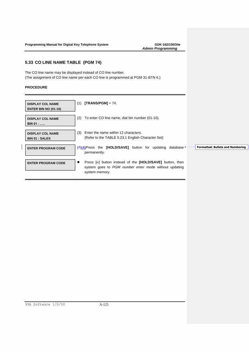
Programming Manual for Digital Key Telephone System GDK-162/100/34e
Admin Programming
99A Software 1/6/00 A-125
5.33 CO LINE NAME TABLE (PGM 74)
The CO line name may be displayed instead of CO line number.
(The assignment of CO line name per each CO line is programmed at PGM 31-BTN 6.)
PROCEDURE
DISPLAY COL NAME
ENTER BIN NO (01-10)
(1) [TRANS/PGM] + 74.
DISPLAY COL NAME
BIN 01 : …..
(2) To enter CO line name, dial bin number (01-10).
DISPLAY COL NAME
BIN 01 : SALES
(3) Enter the name within 12 characters.
(Refer to the TABLE 5.23.1 English Character Set)
ENTER PROGRAM CODE
(7)(4)Press the [HOLD/SAVE] button for updating database
permanently.
ENTER PROGRAM CODE
Press [] button instead of the [HOLD/SAVE] button, then
system goes to PGM number enter mode without updating
system memory.
Formatted: Bullets and Numbering
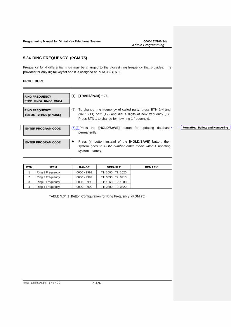
Programming Manual for Digital Key Telephone System GDK-162/100/34e
Admin Programming
99A Software 1/6/00 A-126
5.34 RING FREQUENCY (PGM 75)
Frequency for 4 differential rings may be changed to the closest ring frequency that provides. It is
provided for only digital keyset and it is assigned at PGM 38-BTN 1.
PROCEDURE
RING FREQUENCY
RNG1 RNG2 RNG3 RNG4
(1) [TRANS/PGM] + 75.
RING FREQUENCY
T1:1000 T2:1020 (0:NONE)
(2) To change ring frequency of called party, press BTN 1-4 and
dial 1 (T1) or 2 (T2) and dial 4 digits of new frequency (Ex.
Press BTN 1 to change for new ring 1 frequency).
ENTER PROGRAM CODE
(6)(3)Press the [HOLD/SAVE] button for updating database
permanently.
ENTER PROGRAM CODE
Press [] button instead of the [HOLD/SAVE] button, then
system goes to PGM number enter mode without updating
system memory.
BTN ITEM RANGE DEFAULT REMARK
1 Ring 1 Frequency 0000 - 9999 T1: 1000 T2: 1020
2 Ring 2 Frequency 0000 - 9999 T1: 0890 T2: 0910
3 Ring 3 Frequency 0000 - 9999 T1: 1260 T2: 1280
4 Ring 4 Frequency 0000 - 9999 T1: 0800 T2: 0820
TABLE 5.34.1 Button Configuration for Ring Frequency (PGM 75)
Formatted: Bullets and Numbering

Programming Manual for Digital Key Telephone System GDK-162/100/34e
Admin Programming
99A Software 1/6/00 A-127
5.35 DISTINCT RING FREQUENCY (PGM 76)
Frequency for 4 differential rings can be changed to the closest ring frequency that provides. Station
can give own ring type signal to other station by assigning at PGM 21-BTN 6.
PROCEDURE
DISTINCT RING FREQUENCY
RNG1 RNG2 RNG3 RNG4
(1) [TRANS/PGM] + 76.
RING FREQUENCY
T1:1000 T2:1020 (0:NONE)
(2) To change ring frequency of calling party, press Flex. BTN (1-
4) and dial 1 (T1) or 2 (T2) and dial 4 digits for new frequency
(Ex Press Flex. BTN 1 to change for new ring 1 frequency).
ENTER PROGRAM CODE
(6)(3)Press the [HOLD/SAVE] button for updating database
permanently.
ENTER PROGRAM CODE
Press [] button instead of the [HOLD/SAVE] button, then
system goes to PGM number enter mode without updating
system memory.
BTN ITEM RANGE DEFAULT REMARK
1 Distinct Ring 1 0000 - 9999 T1: 0480 T2: 0000
2 Distinct Ring 2 0000 - 9999 T1: 0400 T2: 0000
3 Distinct Ring 3 0000 - 9999 T1: 0620 T2: 0000
4 Distinct Ring 4 0000 - 9999 T1: 0770 T2: 0000
TABLE 5.35.1 Button Configuration for Distinct Ring Frequency (PGM 76)
Formatted: Bullets and Numbering
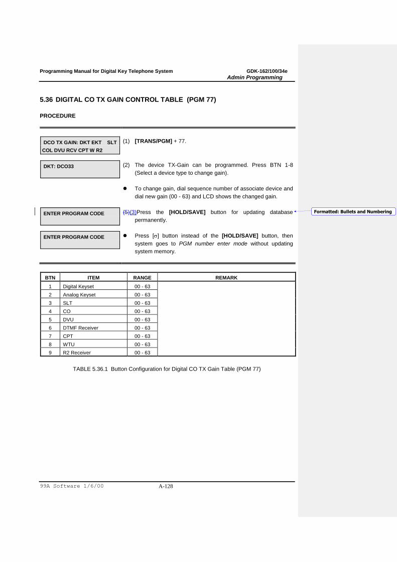
Programming Manual for Digital Key Telephone System GDK-162/100/34e
Admin Programming
99A Software 1/6/00 A-128
5.36 DIGITAL CO TX GAIN CONTROL TABLE (PGM 77)
PROCEDURE
DCO TX GAIN: DKT EKT SLT
COL DVU RCV CPT W R2
(1) [TRANS/PGM] + 77.
DKT: DCO33
(2) The device TX-Gain can be programmed. Press BTN 1-8
(Select a device type to change gain).
To change gain, dial sequence number of associate device and
dial new gain (00 - 63) and LCD shows the changed gain.
ENTER PROGRAM CODE
(5)(3)Press the [HOLD/SAVE] button for updating database
permanently.
ENTER PROGRAM CODE
Press [] button instead of the [HOLD/SAVE] button, then
system goes to PGM number enter mode without updating
system memory.
BTN ITEM RANGE REMARK
1 Digital Keyset 00 - 63
2 Analog Keyset 00 - 63
3 SLT 00 - 63
4 CO 00 - 63
5 DVU 00 - 63
6 DTMF Receiver 00 - 63
7 CPT 00 - 63
8 WTU 00 - 63
9 R2 Receiver 00 - 63
TABLE 5.36.1 Button Configuration for Digital CO TX Gain Table (PGM 77)
Formatted: Bullets and Numbering
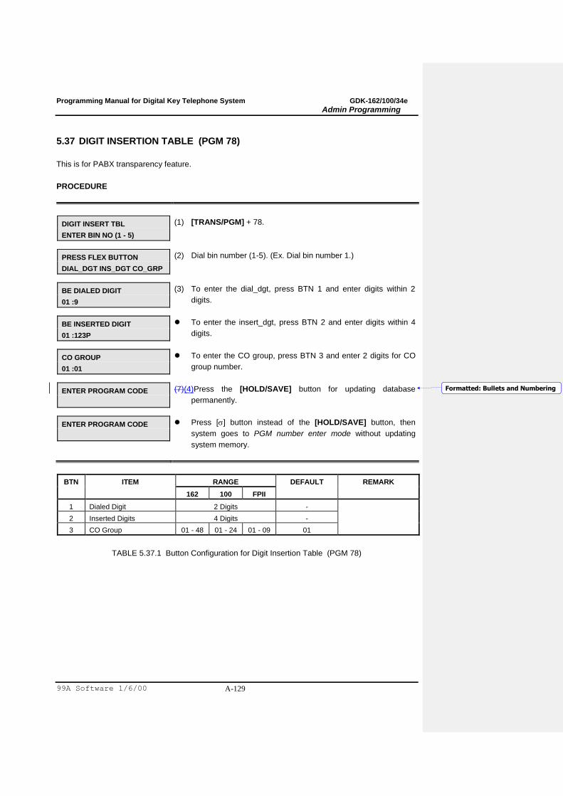
Programming Manual for Digital Key Telephone System GDK-162/100/34e
Admin Programming
99A Software 1/6/00 A-129
5.37 DIGIT INSERTION TABLE (PGM 78)
This is for PABX transparency feature.
PROCEDURE
DIGIT INSERT TBL
ENTER BIN NO (1 - 5)
(1) [TRANS/PGM] + 78.
PRESS FLEX BUTTON
DIAL_DGT INS_DGT CO_GRP
(2) Dial bin number (1-5). (Ex. Dial bin number 1.)
BE DIALED DIGIT
01 :9
(3) To enter the dial_dgt, press BTN 1 and enter digits within 2
digits.
BE INSERTED DIGIT
01 :123P
To enter the insert_dgt, press BTN 2 and enter digits within 4
digits.
CO GROUP
01 :01
To enter the CO group, press BTN 3 and enter 2 digits for CO
group number.
ENTER PROGRAM CODE
(7)(4)Press the [HOLD/SAVE] button for updating database
permanently.
ENTER PROGRAM CODE
Press [] button instead of the [HOLD/SAVE] button, then
system goes to PGM number enter mode without updating
system memory.
BTN ITEM RANGE DEFAULT REMARK
162 100 FPII
1 Dialed Digit 2 Digits -
2 Inserted Digits 4 Digits -
3 CO Group 01 - 48 01 - 24 01 - 09 01
TABLE 5.37.1 Button Configuration for Digit Insertion Table (PGM 78)
Formatted: Bullets and Numbering

Programming Manual for Digital Key Telephone System GDK-162/100/34e
Admin Programming
99A Software 1/6/00 A-130
5.38 CUSTOM CALL ROUTING (PGM 79)
When a call comes into the system through DISA/DID, the external user can route the system by
pressing only one digit. For example, if the station number 100 is recorded in Flex. Button 2 and DISA
external user dials '1', then the call comes to STA 100. To use this feature, DVU (EDVU) must be
installed.
PROCEDURE - 1 (with MEMU in S/W version x.5 or later)
CUSTOM CALL ROUTING
SELECT CCR TABLE (01-09)
(1) [TRANS/PGM] + 79.
To select CCR table number, dial 01~09.
CUSTOM CALL ROUTING : 01
PRESS FLEX KEY (1-10)
To select each entry number of CCR table, press Flex. BTN
1~10, then the entered data will be displayed on the LCD.
CUSTOM CALL ROUTING : 01
DGT 0 : STA 100
(2) To program station number, dial the station number. (Ex. Dial
station number '100')
CUSTOM CALL ROUTING : 01
DGT 0 : HUNT GRP 621
(3) To program Hunt Group, dial a hunt group number. (Ex. Dial
Hunt group 621.)
CUSTOM CALL ROUTING : 01
DGT 0 : DVU ANNC 1
(4) To program system announcement, press the [DND/FOR]
button and dial a DVU system announcement number.
(Ex. Press [DND/FOR] button and dial 1 for Sys. Annc. No.1)
CUSTOM CALL ROUTING : 01
DGT 0 : DVU ANNC 1 (D)
(8)(5)To program system drop the CO line after providing the
announcement, press the [DND/FOR] button, dial a DVU
system announcement number and # button to drop the CO line.
CUSTOM CALL ROUTING : 01
DGT 0 : SPD 10 OF STA 102
(8)(6)To program station speed, press [MUTE] button and dial a
station speed dial number and extension number. (Ex. Pressing
[MUTE] button and dial '10' for station speed number (10) and
extension number '102')
CUSTOM CALL ROUTING : 01
DGT 0 : SYS SPD 399
(8)(7)To program system speed, press [MUTE] button and dial a
system speed number. (Ex. Pressing [MUTE] button and dial
'399' for system speed number )
CUSTOM CALL ROUTING : 01
DGT 0 : INT PAGE 01
(8) To program CO page, dial a page code. (Ex. Dial „401‟ for page
zone 01.)
(8)
CUSTOM CALL ROUTING : 01
DGT 0 : …
(6)(9) To delete the content of entry, press the [SPEED] button.
Formatted: Bullets and Numbering
Formatted: Bullets and Numbering
Formatted: Bullets and Numbering
Formatted: Bullets and Numbering
Formatted: Bullets and Numbering

Programming Manual for Digital Key Telephone System GDK-162/100/34e
Admin Programming
99A Software 1/6/00 A-131
CUSTOM CALL ROUTING : 01
DGT 0 : DVU ANNC 1
(7)(10) Press the [HOLD/SAVE] button for updating database
permanently.
PROCEDURE - 2 (without MEMU)
CUSTOM CALL ROUTING (0-9)
BIN0: ….
(1) [TRANS/PGM] + 79.
CUSTOM CALL ROUTING (0-9)
BIN1: ….
To program, press flex. button 01-10, then it will be displayed
entered data on the LCD. (Ex. Pressing flex. button 2)
CUSTOM CALL ROUTING (0-9)
BIN1: STA 100
(2) To program station number, dial the station number. (Ex. Dial
station number '100')
CUSTOM CALL ROUTING (0-9)
BIN1: HUNT GRP 621
(3) To program Hunt Group, dial a hunt group number. (Ex. Dial
Hunt group 621.)
CUSTOM CALL ROUTING (0-9)
BIN1: DVU ANNC 1
(4) To program system announcement, press '#' key and dial a
DVU system announcement number.
(Ex. Dial '#' key and announcement number 1 for Sys. Annc.
No.1)
CUSTOM CALL ROUTING (0-9)
BIN1: ….
(5) To delete the content of entry, press the [SPEED] button.
CUSTOM CALL ROUTING (0-9)
BIN1: DVU ANNC 1
(6) Press the [HOLD/SAVE] button for updating database
permanently.
Formatted: Bullets and Numbering
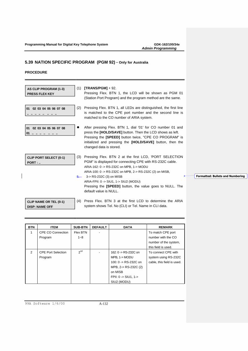
Programming Manual for Digital Key Telephone System GDK-162/100/34e
Admin Programming
99A Software 1/6/00 A-132
5.39 NATION SPECIFIC PROGRAM (PGM 92) - Only for Australia
PROCEDURE
AS CLIP PROGRAM (1-3)
PRESS FLEX KEY
(1) [TRANS/PGM] + 92.
Pressing Flex. BTN 1, the LCD will be shown as PGM 01
(Station Port Program) and the program method are the same.
01 02 03 04 05 06 07 08
.. .. .. .. .. .. .. ..
(2) Pressing Flex. BTN 1, all LEDs are distinguished, the first line
is matched to the CPE port number and the second line is
matched to the CO number of ARIA system.
01 02 03 04 05 06 07 08
01 .. .. .. .. .. .. ..
After pressing Flex. BTN 1, dial '01' for CO number 01 and
press the [HOLD/SAVE] button. Then the LCD shows as left.
Pressing the [SPEED] button twice, "CPE CO PROGRAM" is
initialized and pressing the [HOLD/SAVE] button, then the
changed data is stored.
CLIP PORT SELECT (0-1)
PORT : ..
(3) Pressing Flex. BTN 2 at the first LCD, 'PORT SELECTION
PGM" is displayed for connecting CPE with RS-232C cable.
ARIA-162: 0 -> RS-232C on MPB, 1-> MODU
ARIA-100: 0 -> RS-232C on MPB, 2-> RS-232C (2) on MISB,
5.� 3-> RS-232C (3) on MISB
ARIA-FPII: 0 -> SIU1, 1-> SIU2 (MODU)
Pressing the [SPEED] button, the value goes to NULL. The
default value is NULL.
CLIP NAME OR TEL (0-1)
DISP: NAME OFF
(4) Press Flex. BTN 3 at the first LCD to determine the ARIA
system shows Tel. No (CLI) or Tel. Name in CLI data.
BTN ITEM SUB-BTN DEFAULT DATA REMARK
1 CPE CO Connection
Program
Flex BTN
1~8
- To match CPE port
number with the CO
number of the system,
this field is used.
2 CPE Port Selection
Program
2nd
- 162: 0 -> RS-232C on
MPB, 1-> MODU
100: 0 -> RS-232C on
MPB, 2-> RS-232C (2)
on MISB
FPII: 0 -> SIU1, 1->
SIU2 (MODU)
To connect CPE with
system using RS-232C
cable, this field is used.
Formatted: Bullets and Numbering
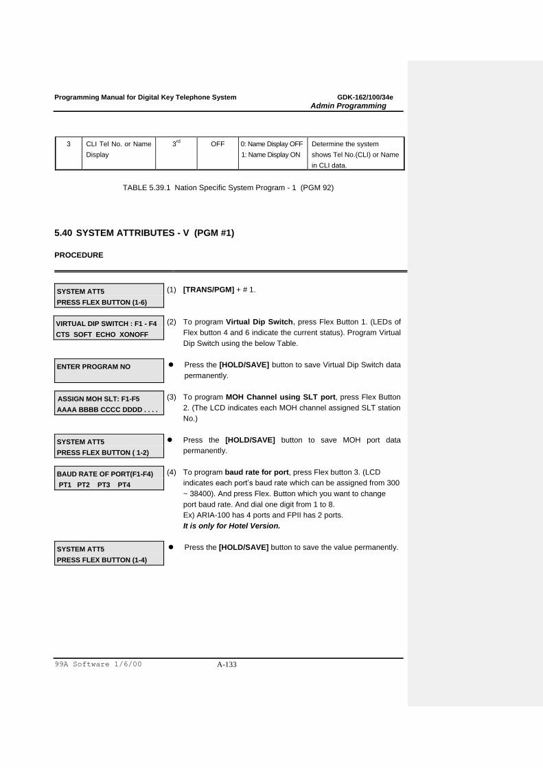
Programming Manual for Digital Key Telephone System GDK-162/100/34e
Admin Programming
99A Software 1/6/00 A-133
3 CLI Tel No. or Name
Display
3rd
OFF 0: Name Display OFF
1: Name Display ON
Determine the system
shows Tel No.(CLI) or Name
in CLI data.
TABLE 5.39.1 Nation Specific System Program - 1 (PGM 92)
5.40 SYSTEM ATTRIBUTES - V (PGM #1)
PROCEDURE
SYSTEM ATT5
PRESS FLEX BUTTON (1-6)
(1) [TRANS/PGM] + # 1.
VIRTUAL DIP SWITCH : F1 - F4
CTS SOFT ECHO XONOFF
(2) To program Virtual Dip Switch, press Flex Button 1. (LEDs of
Flex button 4 and 6 indicate the current status). Program Virtual
Dip Switch using the below Table.
ENTER PROGRAM NO
Press the [HOLD/SAVE] button to save Virtual Dip Switch data
permanently.
ASSIGN MOH SLT: F1-F5
AAAA BBBB CCCC DDDD . . . .
(3) To program MOH Channel using SLT port, press Flex Button
2. (The LCD indicates each MOH channel assigned SLT station
No.)
SYSTEM ATT5
PRESS FLEX BUTTON ( 1-2)
Press the [HOLD/SAVE] button to save MOH port data
permanently.
BAUD RATE OF PORT(F1-F4)
PT1 PT2 PT3 PT4
(4) To program baud rate for port, press Flex button 3. (LCD
indicates each port‟s baud rate which can be assigned from 300
~ 38400). And press Flex. Button which you want to change
port baud rate. And dial one digit from 1 to 8.
Ex) ARIA-100 has 4 ports and FPII has 2 ports.
It is only for Hotel Version.
SYSTEM ATT5
PRESS FLEX BUTTON (1-4)
Press the [HOLD/SAVE] button to save the value permanently.
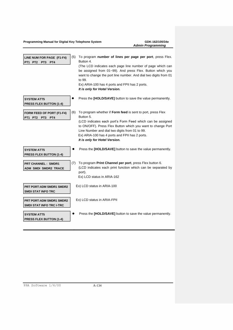
Programming Manual for Digital Key Telephone System GDK-162/100/34e
Admin Programming
99A Software 1/6/00 A-134
LINE NUM FOR PAGE (F1-F4)
PT1 PT2 PT3 PT4
(5) To program number of lines per page per port, press Flex.
Button 4.
(The LCD indicates each page line number of page which can
be assigned from 01~99). And press Flex. Button which you
want to change the port line number. And dial two digits from 01
to 99.
Ex) ARIA-100 has 4 ports and FPII has 2 ports.
It is only for Hotel Version.
SYSTEM ATT5
PRESS FLEX BUTTON (1-4)
Press the [HOLD/SAVE] button to save the value permanently.
FORM FEED OF PORT (F1-F4)
PT1 PT2 PT3 PT4
(6) To program whether if Form feed is sent to port, press Flex
Button 5.
(LCD indicates each port‟s Form Feed which can be assigned
to ON/OFF). Press Flex Button which you want to change Port
Line Number and dial two digits from 01 to 99.
Ex) ARIA-100 has 4 ports and FPII has 2 ports.
It is only for Hotel Version.
SYSTEM ATT5
PRESS FLEX BUTTON (1-4)
Press the [HOLD/SAVE] button to save the value permanently.
PRT CHANNEL : SMDR1
ADM SMDI SMDR2 TRACE
(7) To program Print Channel per port, press Flex button 6.
(LCD indicates each print function which can be separated by
port).
Ex) LCD status in ARIA-162
PRT PORT:ADM SMDR1 SMDR2
SMDI STAT INFO TRC
Ex) LCD status in ARIA-100
PRT PORT:ADM SMDR1 SMDR2
SMDI STAT INFO TRC I-TRC
Ex) LCD status in ARIA-FPII
SYSTEM ATT5
PRESS FLEX BUTTON (1-4)
Press the [HOLD/SAVE] button to save the value permanently.
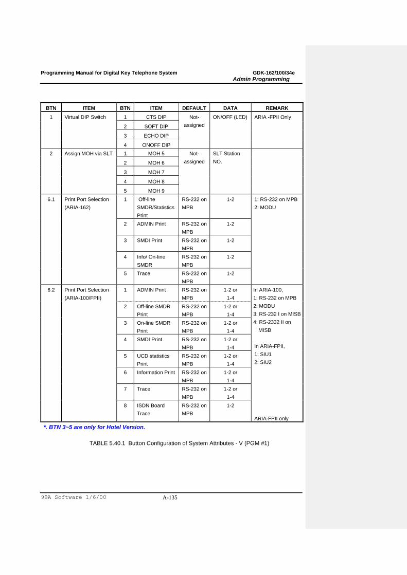
Programming Manual for Digital Key Telephone System GDK-162/100/34e
Admin Programming
99A Software 1/6/00 A-135
BTN ITEM BTN ITEM DEFAULT DATA REMARK
1 Virtual DIP Switch 1 CTS DIP Not-
assigned
ON/OFF (LED) ARIA -FPII Only
2 SOFT DIP
3 ECHO DIP
4 ONOFF DIP
2 Assign MOH via SLT 1 MOH 5 Not-
assigned
SLT Station
NO.
2 MOH 6
3 MOH 7
4 MOH 8
5 MOH 9
6.1
Print Port Selection
(ARIA-162)
1 Off-line
SMDR/Statistics
RS-232 on
MPB
1-2
1: RS-232 on MPB
2: MODU
2 ADMIN Print RS-232 on
MPB
1-2
3 SMDI Print RS-232 on
MPB
1-2
4 Info/ On-line
SMDR
RS-232 on
MPB
1-2
5 Trace RS-232 on
MPB
1-2
6.2
Print Port Selection
(ARIA-100/FPII)
1 ADMIN Print RS-232 on
MPB
1-2 or
1-4
In ARIA-100,
1: RS-232 on MPB
2: MODU
3: RS-232 I on MISB
4: RS-2332 II on
MISB
In ARIA-FPII,
1: SIU1
2: SIU2
ARIA-FPII only
2 Off-line SMDR
RS-232 on
MPB
1-2 or
1-4
3 On-line SMDR
RS-232 on
MPB
1-2 or
1-4
4 SMDI Print RS-232 on
MPB
1-2 or
1-4
5 UCD statistics
RS-232 on
MPB
1-2 or
1-4
6 Information Print RS-232 on
MPB
1-2 or
1-4
7 Trace RS-232 on
MPB
1-2 or
1-4
8 ISDN Board
Trace
RS-232 on
MPB
1-2
*. BTN 3~5 are only for Hotel Version.
TABLE 5.40.1 Button Configuration of System Attributes - V (PGM #1)
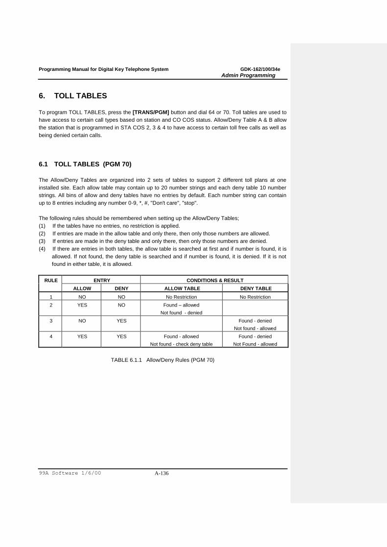
Programming Manual for Digital Key Telephone System GDK-162/100/34e
Admin Programming
99A Software 1/6/00 A-136
6. TOLL TABLES
To program TOLL TABLES, press the [TRANS/PGM] button and dial 64 or 70. Toll tables are used to
have access to certain call types based on station and CO COS status. Allow/Deny Table A & B allow
the station that is programmed in STA COS 2, 3 & 4 to have access to certain toll free calls as well as
being denied certain calls.
6.1 TOLL TABLES (PGM 70)
The Allow/Deny Tables are organized into 2 sets of tables to support 2 different toll plans at one
installed site. Each allow table may contain up to 20 number strings and each deny table 10 number
strings. All bins of allow and deny tables have no entries by default. Each number string can contain
up to 8 entries including any number 0-9, *, #, "Don't care", "stop".
The following rules should be remembered when setting up the Allow/Deny Tables;
(1) If the tables have no entries, no restriction is applied.
(2) If entries are made in the allow table and only there, then only those numbers are allowed.
(3) If entries are made in the deny table and only there, then only those numbers are denied.
(4) If there are entries in both tables, the allow table is searched at first and if number is found, it is
allowed. If not found, the deny table is searched and if number is found, it is denied. If it is not
found in either table, it is allowed.
RULE ENTRY CONDITIONS & RESULT
ALLOW DENY ALLOW TABLE DENY TABLE
1 NO NO No Restriction No Restriction
2 YES NO Found – allowed
Not found - denied
3 NO YES Found - denied
Not found - allowed
4 YES YES Found - allowed
Not found - check deny table
Found - denied
Not Found - allowed
TABLE 6.1.1 Allow/Deny Rules (PGM 70)
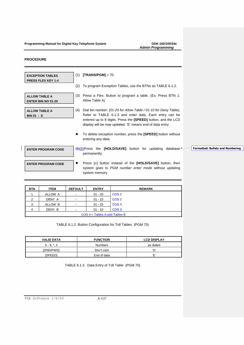
Programming Manual for Digital Key Telephone System GDK-162/100/34e
Admin Programming
99A Software 1/6/00 A-137
PROCEDURE
EXCEPTION TABLES
PRESS FLEX KEY 1-4
(1) [TRANS/PGM] + 70.
(2) To program Exception Tables, use the BTNs as TABLE 6.1.2.
ALLOW TABLE A
ENTER BIN NO 01-20
(3) Press a Flex. Button to program a table. (Ex. Press BTN 1:
Allow Table A)
ALLOW TABLE A
BIN 01 : E
(4) Dial bin number: (01-20 for Allow Table / 01-10 for Deny Table).
Refer to TABLE 6.1.3 and enter data. Each entry can be
entered up to 8 digits. Press the [SPEED] button, and the LCD
display will be now updated. „E‟ means end of data entry.
To delete exception number, press the [SPEED] button without
entering any data.
ENTER PROGRAM CODE
(9)(5)Press the [HOLD/SAVE] button for updating database
permanently.
ENTER PROGRAM CODE
Press [] button instead of the [HOLD/SAVE] button, then
system goes to PGM number enter mode without updating
system memory.
BTN ITEM DEFAULT ENTRY REMARK
1 ALLOW A - 01 - 20 COS 2
2 DENY A - 01 - 10 COS 2
3 ALLOW B - 01 - 20 COS 3
4 DENY B - 01 - 10 COS 3
COS 4 = Tables A and Tables B
TABLE 6.1.2 Button Configuration for Toll Tables (PGM 70)
VALID DATA FUNCTION LCD DISPLAY
0 - 9, *, # Numbers as dialed
[DND/FWD] Don‟t care 'D'
[SPEED] End of data 'E'
TABLE 6.1.3 Data Entry of Toll Table (PGM 70)
Formatted: Bullets and Numbering

Programming Manual for Digital Key Telephone System GDK-162/100/34e
Admin Programming
99A Software 1/6/00 A-138
6.2 CANNED TOLL TABLES (PGM 64)
In addition to the basic toll restrictions, stations with a COS 5 or 6 are subject to dial restrictions based
on the “Canned” Allow and Deny tables. This program permits entries in the Canned Toll Tables. Both
the Allow and Deny Table have 10 bins, each up to 8 digits.
PROCEDURE
CANNED TOLL TABLES
PRESS FLEX KEY 1-2
(1) [TRANS/PGM] + 64.
(2) To program Canned Toll Tables, use the BTNs as TABLE 6.2.1.
ALLOW TABLE
ENTER BIN NO 01-10
(3) Press a Flex. Button to program a table. Press BTN 1: Allow
Tables or press BTN 2: Deny Tables.
ALLOW TABLE
BIN 01 : E
(4) Dial Bin number: (01-10 for Allow Table / 01-10 for Deny
Table). Refer to Table 6.2.2 and enter data. Each entry can be
up to 8 digits. Press the [SPEED] button, and the LCD display
will be now updated. „E‟ means end of data entry.
To delete table entry, press the [SPEED] button without
entering any data.
ENTER PROGRAM CODE
(9)(5)Press the [HOLD/SAVE] button for updating database
permanently.
ENTER PROGRAM CODE
Press [] button instead of the [HOLD/SAVE] button, then
system goes to PGM number enter mode without updating
system memory.
BTN ITEM DEFAULT ENTRY REMARK
1 ALLOW - 01 - 10 COS 5
2 DENY - 01 - 10 COS 6
TABLE 6.2.1 Button Configuration for Canned Toll Table (PGM 64)
VALID DATA FUNCTION LCD DISPLAY
0 - 9, *, # NUMBER as dialed
[DND/FWD] Don‟t Care 'D'
[SPEED] End Of Data 'E'
TABLE 6.2.2 Data Entry of Canned Toll Table (PGM 64)
Formatted: Bullets and Numbering
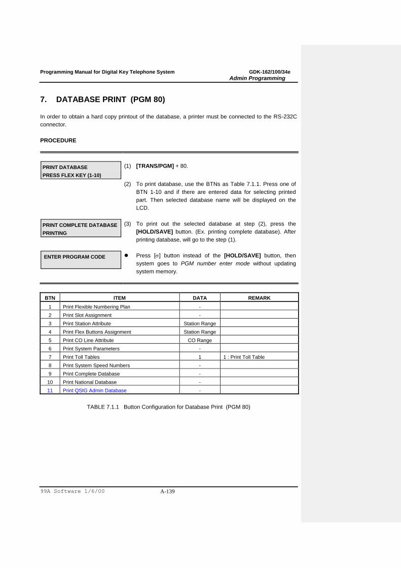
Programming Manual for Digital Key Telephone System GDK-162/100/34e
Admin Programming
99A Software 1/6/00 A-139
7. DATABASE PRINT (PGM 80)
In order to obtain a hard copy printout of the database, a printer must be connected to the RS-232C
connector.
PROCEDURE
PRINT DATABASE
PRESS FLEX KEY (1-10)
(1) [TRANS/PGM] + 80.
(2) To print database, use the BTNs as Table 7.1.1. Press one of
BTN 1-10 and if there are entered data for selecting printed
part. Then selected database name will be displayed on the
LCD.
PRINT COMPLETE DATABASE
PRINTING
(3) To print out the selected database at step (2), press the
[HOLD/SAVE] button. (Ex. printing complete database). After
printing database, will go to the step (1).
ENTER PROGRAM CODE
Press [] button instead of the [HOLD/SAVE] button, then
system goes to PGM number enter mode without updating
system memory.
BTN ITEM DATA REMARK
1 Print Flexible Numbering Plan -
2 Print Slot Assignment -
3 Print Station Attribute Station Range
4 Print Flex Buttons Assignment Station Range
5 Print CO Line Attribute CO Range
6 Print System Parameters -
7 Print Toll Tables 1 1 : Print Toll Table
8 Print System Speed Numbers -
9 Print Complete Database -
10 Print National Database -
11 Print QSIG Admin Database -
TABLE 7.1.1 Button Configuration for Database Print (PGM 80)

Programming Manual for Digital Key Telephone System GDK-162/100/34e
Admin Programming
99A Software 1/6/00 A-140
(Printing Example)
This printing example is in case of ARIA-162 system. In ARIA-100/ARIA-FPII systems, printing
format is the same as ARIA-162 except the system size capacities.
Flexible Numbering Plan B T N 1
FLEXIBLE NUMBERING PLAN ----------------------- FLEX STATION NUMBER 0 1 2 3 4 5 6 7 8 100 101 102 103 104 105 106 107 108 9 10 11 12 13 14 15 16 17 109 110 111 112 113 114 115 116 117 : : : 180 181 182 183 184 185 186 187 188 280 281 282 283 284 285 286 287 288 189 190 191 289 290 291
STATION GROUP PILOT NUMBER : 620 - 649 SLT PGM MODE SELECT NUMBER : 3 INTERNAL PAGE ZONES NUMBER : 401 – 420 INTERNAL ALL CALL PAGE : 43 MEET ME PAGE : 44 EXTERNAL PAGE ZONE 1 : 46 EXTERNAL PAGE ZONE 2 : 47 EXTERNAL ALL CALL PAGE : 48 ALL CALL PAGE : 49 SMDR ACCOUNT CODE ENTER : 50 FLASH COMMAND TO CO LINE : 51 SLT LAST SPD_DIAL : 52 DND : 53 CALL FORWARD : 54 SPEED DIAL PROGRAM : 55 MESSAGE WAIT ENABLE : 56 MESSAGE WAIT RETURN : 57 SPEED DIAL ACCESS : 58 DND/FWD CANCEL : 59 CALL PARK LOCATIONS : 601 - 619 ALARM RESET : 65 GROUP CALL PICK UP : 66 STATION DVU : 67 NIGHT ANSWER : 69 DIRECTED CALL PICK UP : 7 CO GROUP ACCESS : 801 - 848 INDIVIDUAL CO ACCESS : 8801 - 8896 TIE ROUTING : 89 ACCESS CO IN 1ST CO GROUP : 9 ATTENDANT CALL : 0 PRINT SMDR : *0 PRINT SMDR ACCOUNT GROUP : *1 DELETE SMDR : *2 DELETE SMDR ACCOUNT G BASE : *3 DISPLAY CALL CHARGE : *4 ABORT PRINTING : ** RETRIEVE HELD CO 4 BTN : 8## RETRIEVE IND HELD CO 4 BTN : 8#01 - 8#96 DOOR PHONE RELAY 1 : #*1 DOOR PHONE RELAY 2 : #*2 DOOR PHONE RELAY 3 : #*3 DOOR PHONE RELAY 4 : #*4
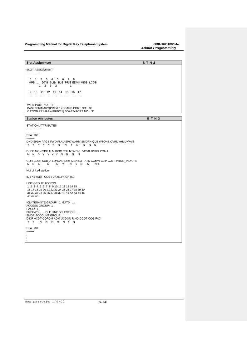
Programming Manual for Digital Key Telephone System GDK-162/100/34e
Admin Programming
99A Software 1/6/00 A-141
Slot Assignment B T N 2
SLOT ASSIGNMENT --------------- 0 1 2 3 4 5 6 7 8 MPB .... DTIB SLIB SLIB PRIB EDVU MISB LCOB 1 2 3 2 1 9 10 11 12 13 14 15 16 17 .... .... .... .... .... .... .... .... .... WTIB PORT NO: 8 BASIC PRIMARY(PRIB/E1) BOARD PORT NO: 30 OPTION PRIMARY(PRIB/E1) BOARD PORT NO: 30
Station Attributes B T N 3
STATION ATTRIBUTES ------------------ STA 100 -------- DND SPDA PAGE FWD PLA ASPK WARM SMDRH QUE WTONE OVRD AHLD WAIT Y Y Y Y Y Y N N Y N N N N DSEC MON SPK ALM IBOX COL NTA DVU VOVR DMRX PCALL N N Y Y Y Y Y N N N N CLIR COLR SUB_A LONG/SHORT MSN EXT/ATD COMW CLIP COLP PROG_IND CPN N N N N N Y N Y N N NO Not Linked station. ID : KEYSET COS : DAY(1)/NIGHT(1) LINE GROUP ACCESS : 1 2 3 4 5 6 7 8 9 10 11 12 13 14 15 16 17 18 19 20 21 22 23 24 25 26 27 28 29 30 31 32 33 34 35 36 37 38 39 40 41 42 43 44 45 46 47 48 ICM TENANCE GROUP: 1 GATD : .... ACCESS GROUP: 1 PAGE: 1 PREFWD: .... IDLE LINE SELECTION: .... SMDR ACCOUNT GROUP: .. DIDR ACDT COPGM ADM UCDON RING CCDT COG FAC Y Y N N N 0 N Y N STA 101 -------- : : :
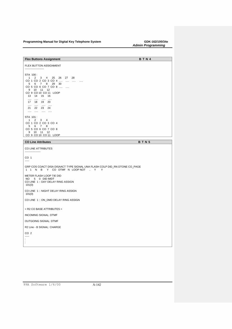
Programming Manual for Digital Key Telephone System GDK-162/100/34e
Admin Programming
99A Software 1/6/00 A-142
Flex Buttons Assignment B T N 4
FLEX BUTTON ASSIGNMENT ---------------------- STA 100 : 1 2 3 4 25 26 27 28 CO 1 CO 2 CO 3 CO 4 ..... ..... ..... ..... 5 6 7 8 29 30 CO 5 CO 6 CO 7 CO 8 ..... ..... 9 10 11 12 CO 9 CO 10 CO 11 LOOP 13 14 15 16 ..... ..... ..... ..... 17 18 19 20 ..... ..... ..... ..... 21 22 23 24 ..... ..... ..... ..... STA 101 : 1 2 3 4 CO 1 CO 2 CO 3 CO 4 5 6 7 8 CO 5 CO 6 CO 7 CO 8 9 10 11 12 CO 9 CO 10 CO 11 LOOP
CO Line Attributes B T N 5
CO LINE ATTRIBUTES ------------------ CO 1 ----- GRP COS COACT DISA DISAACT TYPE SIGNAL UNA FLASH COLP DID_RN DTONE CO_PAGE 1 1 N B Y CO DTMF N LOOP NOT .. Y Y METER FLASH LOOP TIE DID NO 5 0 DID IMDT CO LINE 1 :: DAY DELAY RING ASSIGN 101(0) CO LINE 1 :: NIGHT DELAY RING ASSIGN 101(0) CO LINE 1 :: ON_DMD DELAY RING ASSIGN < R2 CO BASE ATTRIBUTES > INCOMING SIGNAL: DTMF OUTGOING SIGNAL: DTMF R2 Line - B SIGNAL: CHARGE CO 2 ----- : :
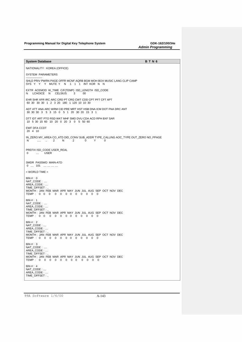
Programming Manual for Digital Key Telephone System GDK-162/100/34e
Admin Programming
99A Software 1/6/00 A-143
System Database B T N 6
NATIONALITY : KOREA (OFFICE) SYSTEM PARAMETERS ------------------ SHLD PRIV PWRN PAGE OFFR MCNF AQRB BGM MOH BOX MUSIC LANG CLIP CAMP SYS Y Y Y MUTE Y N 1 1 1 INT KOR N N EXTR ACEMOD W_TIME C/F(TEMP) ISD_LENGTH ISD_CODE N LCHOICE N CELSIUS 3 00 EHR SHR XFR IRC ARC CRD PT CRG CWT CDD CPT PFT CFT APT 60 30 30 30 1 2 3 20 180 1 120 10 10 30 ADT ATT ANA ARC WRM CID PRE MRT HST HSB DNA ICM DOT FNA DRC ANT 30 30 30 3 5 3 15 0 5 1 20 30 20 15 3 1 DTT IDT ART PTO RSD WKT MHF SMD DVU CDA ACD RPH BXF SAR 10 5 30 15 60 10 20 0 20 3 0 5 50 60 EWF DFA CCDT 20 4 10 IN_ZERO MY_AREA CO_ATD DID_CONV SUB_ADDR TYPE_CALLING AOC_TYPE OUT_ZERO NO_FPAGE N ..... .. 2 N 2 0 Y 0 PREFIX ISD_CODE USER_REAL 0 .... USER SMDR PASSWD MAIN-ATD 0 .... 101 .... .... .... .... < WORLD TIME > BIN # : 0 NAT_CODE : .... AREA_CODE : .... TIME_OFFSET : .. MONTH : JAN FEB MAR APR MAY JUN JUL AUG SEP OCT NOV DEC TEMP : 0 0 0 0 0 0 0 0 0 0 0 0 BIN # : 1 NAT_CODE : .... AREA_CODE : .... TIME_OFFSET : .. MONTH : JAN FEB MAR APR MAY JUN JUL AUG SEP OCT NOV DEC TEMP : 0 0 0 0 0 0 0 0 0 0 0 0 BIN # : 2 NAT_CODE : .... AREA_CODE : .... TIME_OFFSET : .. MONTH : JAN FEB MAR APR MAY JUN JUL AUG SEP OCT NOV DEC TEMP : 0 0 0 0 0 0 0 0 0 0 0 0 BIN # : 3 NAT_CODE : .... AREA_CODE : .... TIME_OFFSET : .. MONTH : JAN FEB MAR APR MAY JUN JUL AUG SEP OCT NOV DEC TEMP : 0 0 0 0 0 0 0 0 0 0 0 0 BIN # : 4 NAT_CODE : .... AREA_CODE : .... TIME_OFFSET : ..
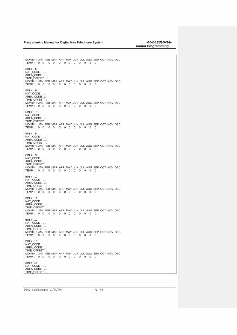
Programming Manual for Digital Key Telephone System GDK-162/100/34e
Admin Programming
99A Software 1/6/00 A-144
MONTH : JAN FEB MAR APR MAY JUN JUL AUG SEP OCT NOV DEC TEMP : 0 0 0 0 0 0 0 0 0 0 0 0 BIN # : 5 NAT_CODE : .... AREA_CODE : .... TIME_OFFSET : .. MONTH : JAN FEB MAR APR MAY JUN JUL AUG SEP OCT NOV DEC TEMP : 0 0 0 0 0 0 0 0 0 0 0 0 BIN # : 6 NAT_CODE : .... AREA_CODE : .... TIME_OFFSET : .. MONTH : JAN FEB MAR APR MAY JUN JUL AUG SEP OCT NOV DEC TEMP : 0 0 0 0 0 0 0 0 0 0 0 0 BIN # : 7 NAT_CODE : .... AREA_CODE : .... TIME_OFFSET : .. MONTH : JAN FEB MAR APR MAY JUN JUL AUG SEP OCT NOV DEC TEMP : 0 0 0 0 0 0 0 0 0 0 0 0 BIN # : 8 NAT_CODE : .... AREA_CODE : .... TIME_OFFSET : .. MONTH : JAN FEB MAR APR MAY JUN JUL AUG SEP OCT NOV DEC TEMP : 0 0 0 0 0 0 0 0 0 0 0 0 BIN # : 9 NAT_CODE : .... AREA_CODE : .... TIME_OFFSET : .. MONTH : JAN FEB MAR APR MAY JUN JUL AUG SEP OCT NOV DEC TEMP : 0 0 0 0 0 0 0 0 0 0 0 0 BIN # : 10 NAT_CODE : .... AREA_CODE : .... TIME_OFFSET : .. MONTH : JAN FEB MAR APR MAY JUN JUL AUG SEP OCT NOV DEC TEMP : 0 0 0 0 0 0 0 0 0 0 0 0 BIN # : 11 NAT_CODE : .... AREA_CODE : .... TIME_OFFSET : .. MONTH : JAN FEB MAR APR MAY JUN JUL AUG SEP OCT NOV DEC TEMP : 0 0 0 0 0 0 0 0 0 0 0 0 BIN # : 12 NAT_CODE : .... AREA_CODE : .... TIME_OFFSET : .. MONTH : JAN FEB MAR APR MAY JUN JUL AUG SEP OCT NOV DEC TEMP : 0 0 0 0 0 0 0 0 0 0 0 0 BIN # : 13 NAT_CODE : .... AREA_CODE : .... TIME_OFFSET : .. MONTH : JAN FEB MAR APR MAY JUN JUL AUG SEP OCT NOV DEC TEMP : 0 0 0 0 0 0 0 0 0 0 0 0 BIN # : 14 NAT_CODE : .... AREA_CODE : .... TIME_OFFSET : ..
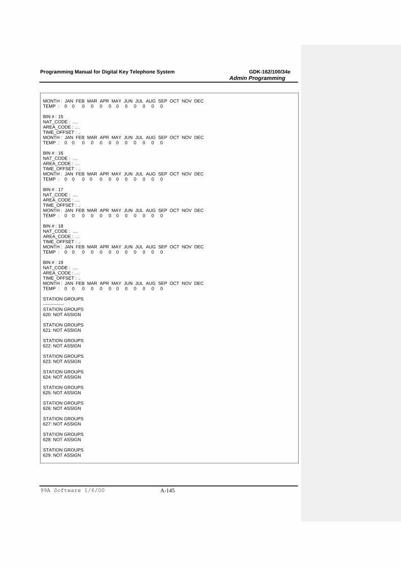
Programming Manual for Digital Key Telephone System GDK-162/100/34e
Admin Programming
99A Software 1/6/00 A-145
MONTH : JAN FEB MAR APR MAY JUN JUL AUG SEP OCT NOV DEC TEMP : 0 0 0 0 0 0 0 0 0 0 0 0 BIN # : 15 NAT_CODE : .... AREA_CODE : .... TIME_OFFSET : .. MONTH : JAN FEB MAR APR MAY JUN JUL AUG SEP OCT NOV DEC TEMP : 0 0 0 0 0 0 0 0 0 0 0 0 BIN # : 16 NAT_CODE : .... AREA_CODE : .... TIME_OFFSET : .. MONTH : JAN FEB MAR APR MAY JUN JUL AUG SEP OCT NOV DEC TEMP : 0 0 0 0 0 0 0 0 0 0 0 0 BIN # : 17 NAT_CODE : .... AREA_CODE : .... TIME_OFFSET : .. MONTH : JAN FEB MAR APR MAY JUN JUL AUG SEP OCT NOV DEC TEMP : 0 0 0 0 0 0 0 0 0 0 0 0 BIN # : 18 NAT_CODE : .... AREA_CODE : .... TIME_OFFSET : .. MONTH : JAN FEB MAR APR MAY JUN JUL AUG SEP OCT NOV DEC TEMP : 0 0 0 0 0 0 0 0 0 0 0 0 BIN # : 19 NAT_CODE : .... AREA_CODE : .... TIME_OFFSET : .. MONTH : JAN FEB MAR APR MAY JUN JUL AUG SEP OCT NOV DEC TEMP : 0 0 0 0 0 0 0 0 0 0 0 0 STATION GROUPS -------------- STATION GROUPS 620: NOT ASSIGN STATION GROUPS 621: NOT ASSIGN STATION GROUPS 622: NOT ASSIGN STATION GROUPS 623: NOT ASSIGN STATION GROUPS 624: NOT ASSIGN STATION GROUPS 625: NOT ASSIGN STATION GROUPS 626: NOT ASSIGN STATION GROUPS 627: NOT ASSIGN STATION GROUPS 628: NOT ASSIGN STATION GROUPS 629: NOT ASSIGN
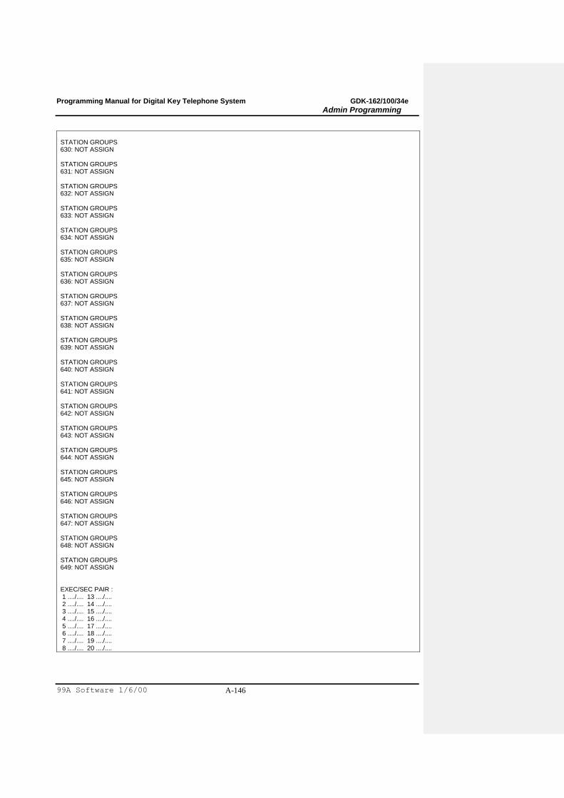
Programming Manual for Digital Key Telephone System GDK-162/100/34e
Admin Programming
99A Software 1/6/00 A-146
STATION GROUPS 630: NOT ASSIGN STATION GROUPS 631: NOT ASSIGN STATION GROUPS 632: NOT ASSIGN STATION GROUPS 633: NOT ASSIGN STATION GROUPS 634: NOT ASSIGN STATION GROUPS 635: NOT ASSIGN STATION GROUPS 636: NOT ASSIGN STATION GROUPS 637: NOT ASSIGN STATION GROUPS 638: NOT ASSIGN STATION GROUPS 639: NOT ASSIGN STATION GROUPS 640: NOT ASSIGN STATION GROUPS 641: NOT ASSIGN STATION GROUPS 642: NOT ASSIGN STATION GROUPS 643: NOT ASSIGN STATION GROUPS 644: NOT ASSIGN STATION GROUPS 645: NOT ASSIGN STATION GROUPS 646: NOT ASSIGN STATION GROUPS 647: NOT ASSIGN STATION GROUPS 648: NOT ASSIGN STATION GROUPS 649: NOT ASSIGN EXEC/SEC PAIR : 1 ..../.... 13 ..../.... 2 ..../.... 14 ..../.... 3 ..../.... 15 ..../.... 4 ..../.... 16 ..../.... 5 ..../.... 17 ..../.... 6 ..../.... 18 ..../.... 7 ..../.... 19 ..../.... 8 ..../.... 20 ..../....
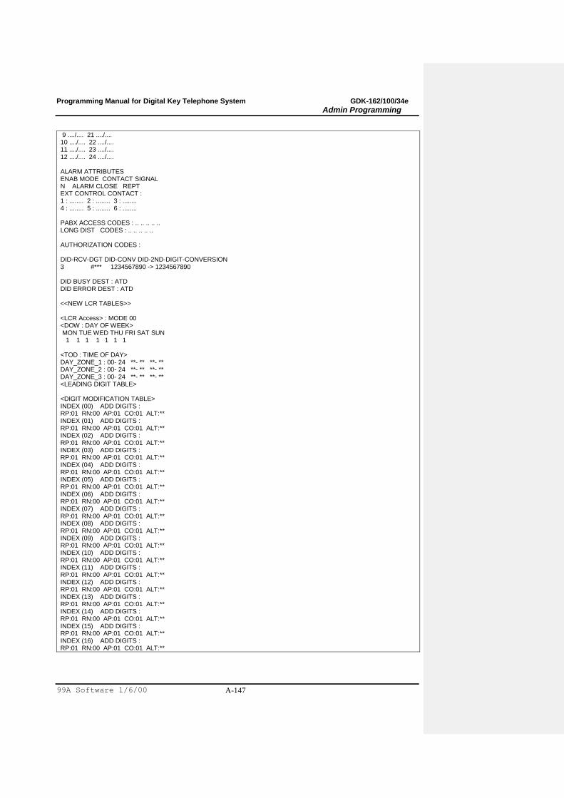
Programming Manual for Digital Key Telephone System GDK-162/100/34e
Admin Programming
99A Software 1/6/00 A-147
9 ..../.... 21 ..../.... 10 ..../.... 22 ..../.... 11 ..../.... 23 ..../.... 12 ..../.... 24 ..../.... ALARM ATTRIBUTES ENAB MODE CONTACT SIGNAL N ALARM CLOSE REPT EXT CONTROL CONTACT : 1 : ........ 2 : ........ 3 : ........ 4 : ........ 5 : ........ 6 : ........ PABX ACCESS CODES : .. .. .. .. .. LONG DIST CODES : .. .. .. .. .. AUTHORIZATION CODES : DID-RCV-DGT DID-CONV DID-2ND-DIGIT-CONVERSION 3 #*** 1234567890 -> 1234567890 DID BUSY DEST : ATD DID ERROR DEST : ATD <<NEW LCR TABLES>> <LCR Access> : MODE 00 <DOW : DAY OF WEEK> MON TUE WED THU FRI SAT SUN 1 1 1 1 1 1 1 <TOD : TIME OF DAY> DAY_ZONE_1 : 00- 24 **- ** **- ** DAY_ZONE_2 : 00- 24 **- ** **- ** DAY_ZONE_3 : 00- 24 **- ** **- ** <LEADING DIGIT TABLE> <DIGIT MODIFICATION TABLE> INDEX (00) ADD DIGITS : RP:01 RN:00 AP:01 CO:01 ALT:** INDEX (01) ADD DIGITS : RP:01 RN:00 AP:01 CO:01 ALT:** INDEX (02) ADD DIGITS : RP:01 RN:00 AP:01 CO:01 ALT:** INDEX (03) ADD DIGITS : RP:01 RN:00 AP:01 CO:01 ALT:** INDEX (04) ADD DIGITS : RP:01 RN:00 AP:01 CO:01 ALT:** INDEX (05) ADD DIGITS : RP:01 RN:00 AP:01 CO:01 ALT:** INDEX (06) ADD DIGITS : RP:01 RN:00 AP:01 CO:01 ALT:** INDEX (07) ADD DIGITS : RP:01 RN:00 AP:01 CO:01 ALT:** INDEX (08) ADD DIGITS : RP:01 RN:00 AP:01 CO:01 ALT:** INDEX (09) ADD DIGITS : RP:01 RN:00 AP:01 CO:01 ALT:** INDEX (10) ADD DIGITS : RP:01 RN:00 AP:01 CO:01 ALT:** INDEX (11) ADD DIGITS : RP:01 RN:00 AP:01 CO:01 ALT:** INDEX (12) ADD DIGITS : RP:01 RN:00 AP:01 CO:01 ALT:** INDEX (13) ADD DIGITS : RP:01 RN:00 AP:01 CO:01 ALT:** INDEX (14) ADD DIGITS : RP:01 RN:00 AP:01 CO:01 ALT:** INDEX (15) ADD DIGITS : RP:01 RN:00 AP:01 CO:01 ALT:** INDEX (16) ADD DIGITS : RP:01 RN:00 AP:01 CO:01 ALT:**
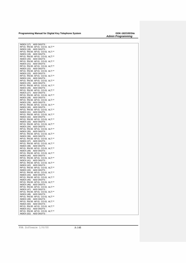
Programming Manual for Digital Key Telephone System GDK-162/100/34e
Admin Programming
99A Software 1/6/00 A-148
INDEX (17) ADD DIGITS : RP:01 RN:00 AP:01 CO:01 ALT:** INDEX (18) ADD DIGITS : RP:01 RN:00 AP:01 CO:01 ALT:** INDEX (19) ADD DIGITS : RP:01 RN:00 AP:01 CO:01 ALT:** INDEX (20) ADD DIGITS : RP:01 RN:00 AP:01 CO:01 ALT:** INDEX (21) ADD DIGITS : RP:01 RN:00 AP:01 CO:01 ALT:** INDEX (22) ADD DIGITS : RP:01 RN:00 AP:01 CO:01 ALT:** INDEX (23) ADD DIGITS : RP:01 RN:00 AP:01 CO:01 ALT:** INDEX (24) ADD DIGITS : RP:01 RN:00 AP:01 CO:01 ALT:** INDEX (25) ADD DIGITS : RP:01 RN:00 AP:01 CO:01 ALT:** INDEX (26) ADD DIGITS : RP:01 RN:00 AP:01 CO:01 ALT:** INDEX (27) ADD DIGITS : RP:01 RN:00 AP:01 CO:01 ALT:** INDEX (28) ADD DIGITS : RP:01 RN:00 AP:01 CO:01 ALT:** INDEX (29) ADD DIGITS : RP:01 RN:00 AP:01 CO:01 ALT:** INDEX (30) ADD DIGITS : RP:01 RN:00 AP:01 CO:01 ALT:** INDEX (31) ADD DIGITS : RP:01 RN:00 AP:01 CO:01 ALT:** INDEX (32) ADD DIGITS : RP:01 RN:00 AP:01 CO:01 ALT:** INDEX (33) ADD DIGITS : RP:01 RN:00 AP:01 CO:01 ALT:** INDEX (34) ADD DIGITS : RP:01 RN:00 AP:01 CO:01 ALT:** INDEX (35) ADD DIGITS : RP:01 RN:00 AP:01 CO:01 ALT:** INDEX (36) ADD DIGITS : RP:01 RN:00 AP:01 CO:01 ALT:** INDEX (37) ADD DIGITS : RP:01 RN:00 AP:01 CO:01 ALT:** INDEX (38) ADD DIGITS : RP:01 RN:00 AP:01 CO:01 ALT:** INDEX (39) ADD DIGITS : RP:01 RN:00 AP:01 CO:01 ALT:** INDEX (40) ADD DIGITS : RP:01 RN:00 AP:01 CO:01 ALT:** INDEX (41) ADD DIGITS : RP:01 RN:00 AP:01 CO:01 ALT:** INDEX (42) ADD DIGITS : RP:01 RN:00 AP:01 CO:01 ALT:** INDEX (43) ADD DIGITS : RP:01 RN:00 AP:01 CO:01 ALT:** INDEX (44) ADD DIGITS : RP:01 RN:00 AP:01 CO:01 ALT:** INDEX (45) ADD DIGITS : RP:01 RN:00 AP:01 CO:01 ALT:** INDEX (46) ADD DIGITS : RP:01 RN:00 AP:01 CO:01 ALT:** INDEX (47) ADD DIGITS : RP:01 RN:00 AP:01 CO:01 ALT:** INDEX (48) ADD DIGITS : RP:01 RN:00 AP:01 CO:01 ALT:** INDEX (49) ADD DIGITS : RP:01 RN:00 AP:01 CO:01 ALT:** INDEX (50) ADD DIGITS : RP:01 RN:00 AP:01 CO:01 ALT:** INDEX (51) ADD DIGITS : RP:01 RN:00 AP:01 CO:01 ALT:** INDEX (52) ADD DIGITS :

Programming Manual for Digital Key Telephone System GDK-162/100/34e
Admin Programming
99A Software 1/6/00 A-149
RP:01 RN:00 AP:01 CO:01 ALT:** INDEX (53) ADD DIGITS : RP:01 RN:00 AP:01 CO:01 ALT:** INDEX (54) ADD DIGITS : RP:01 RN:00 AP:01 CO:01 ALT:** INDEX (55) ADD DIGITS : RP:01 RN:00 AP:01 CO:01 ALT:** INDEX (56) ADD DIGITS : RP:01 RN:00 AP:01 CO:01 ALT:** INDEX (57) ADD DIGITS : RP:01 RN:00 AP:01 CO:01 ALT:** INDEX (58) ADD DIGITS : RP:01 RN:00 AP:01 CO:01 ALT:** INDEX (59) ADD DIGITS : RP:01 RN:00 AP:01 CO:01 ALT:** INDEX (60) ADD DIGITS : RP:01 RN:00 AP:01 CO:01 ALT:** INDEX (61) ADD DIGITS : RP:01 RN:00 AP:01 CO:01 ALT:** INDEX (62) ADD DIGITS : RP:01 RN:00 AP:01 CO:01 ALT:** INDEX (63) ADD DIGITS : RP:01 RN:00 AP:01 CO:01 ALT:** INDEX (64) ADD DIGITS : RP:01 RN:00 AP:01 CO:01 ALT:** INDEX (65) ADD DIGITS : RP:01 RN:00 AP:01 CO:01 ALT:** INDEX (66) ADD DIGITS : RP:01 RN:00 AP:01 CO:01 ALT:** INDEX (67) ADD DIGITS : RP:01 RN:00 AP:01 CO:01 ALT:** INDEX (68) ADD DIGITS : RP:01 RN:00 AP:01 CO:01 ALT:** INDEX (69) ADD DIGITS : RP:01 RN:00 AP:01 CO:01 ALT:** INDEX (70) ADD DIGITS : RP:01 RN:00 AP:01 CO:01 ALT:** INDEX (71) ADD DIGITS : RP:01 RN:00 AP:01 CO:01 ALT:** INDEX (72) ADD DIGITS : RP:01 RN:00 AP:01 CO:01 ALT:** INDEX (73) ADD DIGITS : RP:01 RN:00 AP:01 CO:01 ALT:** INDEX (74) ADD DIGITS : RP:01 RN:00 AP:01 CO:01 ALT:** INDEX (75) ADD DIGITS : RP:01 RN:00 AP:01 CO:01 ALT:** INDEX (76) ADD DIGITS : RP:01 RN:00 AP:01 CO:01 ALT:** INDEX (77) ADD DIGITS : RP:01 RN:00 AP:01 CO:01 ALT:** INDEX (78) ADD DIGITS : RP:01 RN:00 AP:01 CO:01 ALT:** INDEX (79) ADD DIGITS : RP:01 RN:00 AP:01 CO:01 ALT:** INDEX (80) ADD DIGITS : RP:01 RN:00 AP:01 CO:01 ALT:** INDEX (81) ADD DIGITS : RP:01 RN:00 AP:01 CO:01 ALT:** INDEX (82) ADD DIGITS : RP:01 RN:00 AP:01 CO:01 ALT:** INDEX (83) ADD DIGITS : RP:01 RN:00 AP:01 CO:01 ALT:** INDEX (84) ADD DIGITS : RP:01 RN:00 AP:01 CO:01 ALT:** INDEX (85) ADD DIGITS : RP:01 RN:00 AP:01 CO:01 ALT:** INDEX (86) ADD DIGITS : RP:01 RN:00 AP:01 CO:01 ALT:** INDEX (87) ADD DIGITS : RP:01 RN:00 AP:01 CO:01 ALT:**
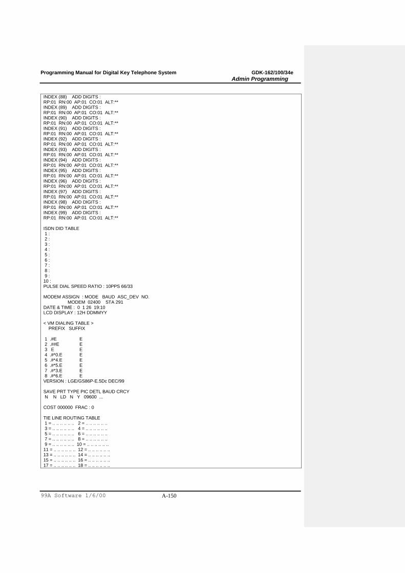
Programming Manual for Digital Key Telephone System GDK-162/100/34e
Admin Programming
99A Software 1/6/00 A-150
INDEX (88) ADD DIGITS : RP:01 RN:00 AP:01 CO:01 ALT:** INDEX (89) ADD DIGITS : RP:01 RN:00 AP:01 CO:01 ALT:** INDEX (90) ADD DIGITS : RP:01 RN:00 AP:01 CO:01 ALT:** INDEX (91) ADD DIGITS : RP:01 RN:00 AP:01 CO:01 ALT:** INDEX (92) ADD DIGITS : RP:01 RN:00 AP:01 CO:01 ALT:** INDEX (93) ADD DIGITS : RP:01 RN:00 AP:01 CO:01 ALT:** INDEX (94) ADD DIGITS : RP:01 RN:00 AP:01 CO:01 ALT:** INDEX (95) ADD DIGITS : RP:01 RN:00 AP:01 CO:01 ALT:** INDEX (96) ADD DIGITS : RP:01 RN:00 AP:01 CO:01 ALT:** INDEX (97) ADD DIGITS : RP:01 RN:00 AP:01 CO:01 ALT:** INDEX (98) ADD DIGITS : RP:01 RN:00 AP:01 CO:01 ALT:** INDEX (99) ADD DIGITS : RP:01 RN:00 AP:01 CO:01 ALT:** ISDN DID TABLE 1 : 2 : 3 : 4 : 5 : 6 : 7 : 8 : 9 : 10 : PULSE DIAL SPEED RATIO : 10PPS 66/33 MODEM ASSIGN : MODE BAUD ASC_DEV NO. MODEM 02400 STA 291 DATE & TIME : 0 1 26 19:10 LCD DISPLAY : 12H DDMMYY < VM DIALING TABLE > PREFIX SUFFIX 1 .#E E 2 .##E E 3 E E 4 .#*0.E E 5 .#*4.E E 6 .#*5.E E 7 .#*3.E E 8 .#*6.E E VERSION : LGE/GS86P-E.5Dc DEC/99 SAVE PRT TYPE PIC DETL BAUD CRCY N N LD N Y 09600 ... COST 000000 FRAC : 0 TIE LINE ROUTING TABLE 1 = .. .. .. .. .. .. 2 = .. .. .. .. .. .. 3 = .. .. .. .. .. .. 4 = .. .. .. .. .. .. 5 = .. .. .. .. .. .. 6 = .. .. .. .. .. .. 7 = .. .. .. .. .. .. 8 = .. .. .. .. .. .. 9 = .. .. .. .. .. .. 10 = .. .. .. .. .. .. 11 = .. .. .. .. .. .. 12 = .. .. .. .. .. .. 13 = .. .. .. .. .. .. 14 = .. .. .. .. .. .. 15 = .. .. .. .. .. .. 16 = .. .. .. .. .. .. 17 = .. .. .. .. .. .. 18 = .. .. .. .. .. ..
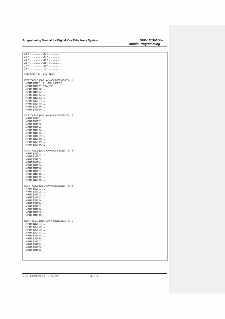
Programming Manual for Digital Key Telephone System GDK-162/100/34e
Admin Programming
99A Software 1/6/00 A-151
19 = .. .. .. .. .. .. 20 = .. .. .. .. .. .. 21 = .. .. .. .. .. .. 22 = .. .. .. .. .. .. 23 = .. .. .. .. .. .. 24 = .. .. .. .. .. .. 25 = .. .. .. .. .. .. 26 = .. .. .. .. .. .. 27 = .. .. .. .. .. .. 28 = .. .. .. .. .. .. 29 = .. .. .. .. .. .. 30 = .. .. .. .. .. .. CUSTOM CALL ROUTING CCR TABLE (DVU ANNOUNCEMENT) : 1 INPUT DGT 1 : ALL CALL PAGE INPUT DGT 2 : STA 102 INPUT DGT 3 : ... INPUT DGT 4 : ... INPUT DGT 5 : ... INPUT DGT 6 : ... INPUT DGT 7 : ... INPUT DGT 8 : ... INPUT DGT 9 : ... INPUT DGT 0 : ... CCR TABLE (DVU ANNOUNCEMENT) : 2 INPUT DGT 1 : ... INPUT DGT 2 : ... INPUT DGT 3 : ... INPUT DGT 4 : ... INPUT DGT 5 : ... INPUT DGT 6 : ... INPUT DGT 7 : ... INPUT DGT 8 : ... INPUT DGT 9 : ... INPUT DGT 0 : ... CCR TABLE (DVU ANNOUNCEMENT) : 3 INPUT DGT 1 : ... INPUT DGT 2 : ... INPUT DGT 3 : ... INPUT DGT 4 : ... INPUT DGT 5 : ... INPUT DGT 6 : ... INPUT DGT 7 : ... INPUT DGT 8 : ... INPUT DGT 9 : ... INPUT DGT 0 : ... CCR TABLE (DVU ANNOUNCEMENT) : 4 INPUT DGT 1 : ... INPUT DGT 2 : ... INPUT DGT 3 : ... INPUT DGT 4 : ... INPUT DGT 5 : ... INPUT DGT 6 : ... INPUT DGT 7 : ... INPUT DGT 8 : ... INPUT DGT 9 : ... INPUT DGT 0 : ... CCR TABLE (DVU ANNOUNCEMENT) : 5 INPUT DGT 1 : ... INPUT DGT 2 : ... INPUT DGT 3 : ... INPUT DGT 4 : ... INPUT DGT 5 : ... INPUT DGT 6 : ... INPUT DGT 7 : ... INPUT DGT 8 : ... INPUT DGT 9 : ... INPUT DGT 0 : ...
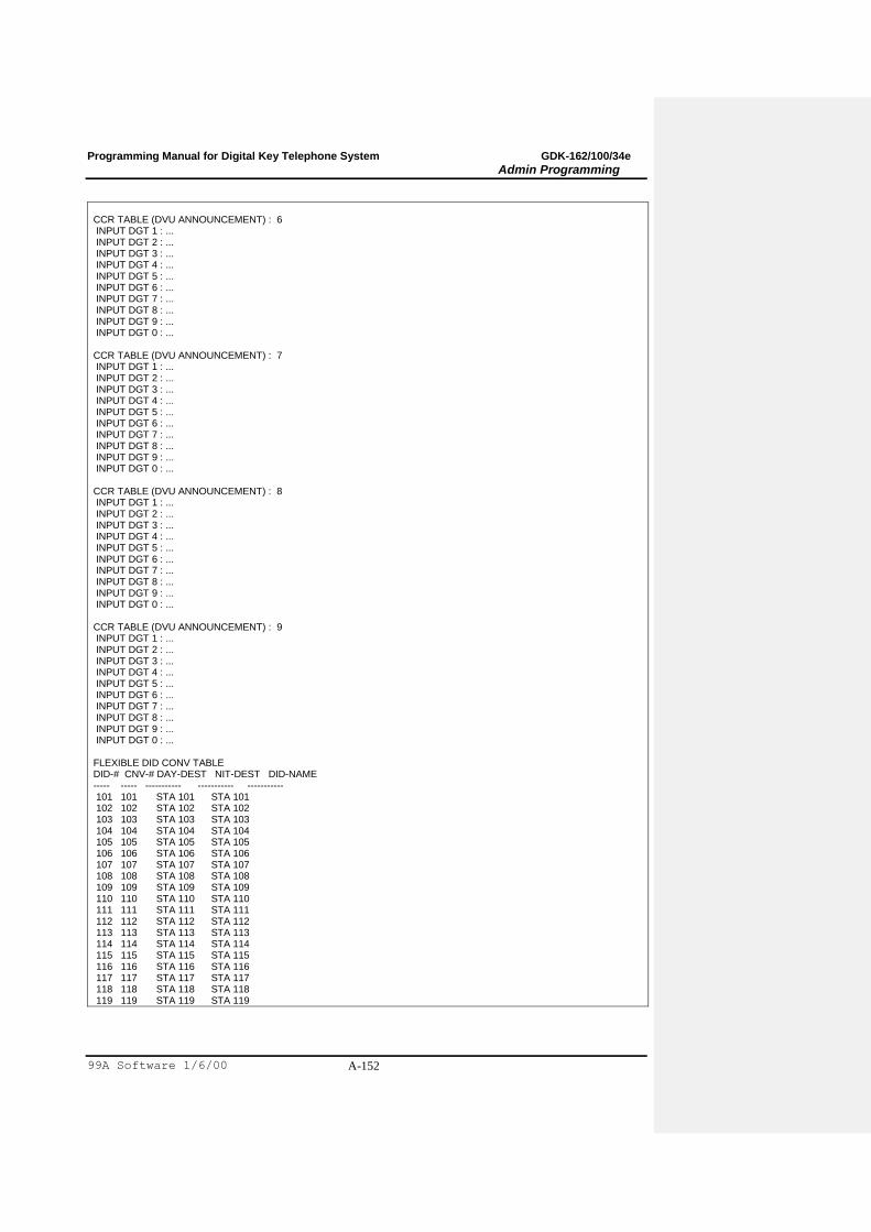
Programming Manual for Digital Key Telephone System GDK-162/100/34e
Admin Programming
99A Software 1/6/00 A-152
CCR TABLE (DVU ANNOUNCEMENT) : 6 INPUT DGT 1 : ... INPUT DGT 2 : ... INPUT DGT 3 : ... INPUT DGT 4 : ... INPUT DGT 5 : ... INPUT DGT 6 : ... INPUT DGT 7 : ... INPUT DGT 8 : ... INPUT DGT 9 : ... INPUT DGT 0 : ... CCR TABLE (DVU ANNOUNCEMENT) : 7 INPUT DGT 1 : ... INPUT DGT 2 : ... INPUT DGT 3 : ... INPUT DGT 4 : ... INPUT DGT 5 : ... INPUT DGT 6 : ... INPUT DGT 7 : ... INPUT DGT 8 : ... INPUT DGT 9 : ... INPUT DGT 0 : ... CCR TABLE (DVU ANNOUNCEMENT) : 8 INPUT DGT 1 : ... INPUT DGT 2 : ... INPUT DGT 3 : ... INPUT DGT 4 : ... INPUT DGT 5 : ... INPUT DGT 6 : ... INPUT DGT 7 : ... INPUT DGT 8 : ... INPUT DGT 9 : ... INPUT DGT 0 : ... CCR TABLE (DVU ANNOUNCEMENT) : 9 INPUT DGT 1 : ... INPUT DGT 2 : ... INPUT DGT 3 : ... INPUT DGT 4 : ... INPUT DGT 5 : ... INPUT DGT 6 : ... INPUT DGT 7 : ... INPUT DGT 8 : ... INPUT DGT 9 : ... INPUT DGT 0 : ... FLEXIBLE DID CONV TABLE DID-# CNV-# DAY-DEST NIT-DEST DID-NAME ----- ----- ----------- ----------- ----------- 101 101 STA 101 STA 101 102 102 STA 102 STA 102 103 103 STA 103 STA 103 104 104 STA 104 STA 104 105 105 STA 105 STA 105 106 106 STA 106 STA 106 107 107 STA 107 STA 107 108 108 STA 108 STA 108 109 109 STA 109 STA 109 110 110 STA 110 STA 110 111 111 STA 111 STA 111 112 112 STA 112 STA 112 113 113 STA 113 STA 113 114 114 STA 114 STA 114 115 115 STA 115 STA 115 116 116 STA 116 STA 116 117 117 STA 117 STA 117 118 118 STA 118 STA 118 119 119 STA 119 STA 119
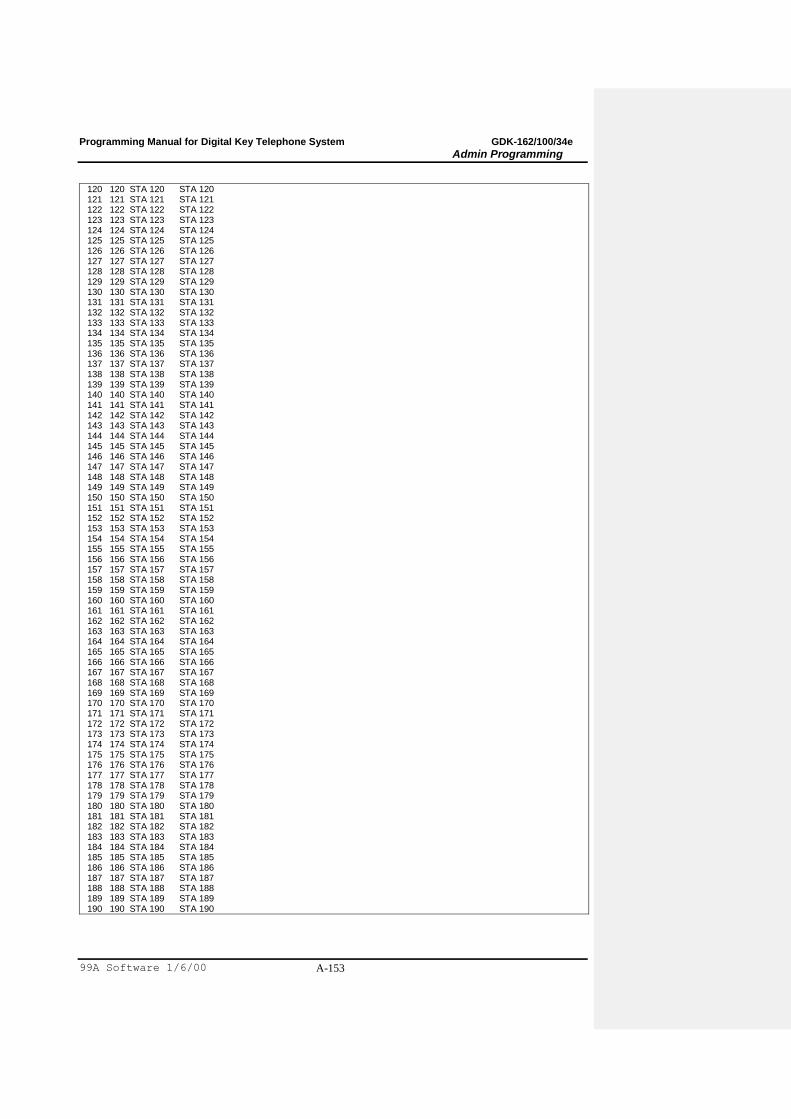
Programming Manual for Digital Key Telephone System GDK-162/100/34e
Admin Programming
99A Software 1/6/00 A-153
120 120 STA 120 STA 120 121 121 STA 121 STA 121 122 122 STA 122 STA 122 123 123 STA 123 STA 123 124 124 STA 124 STA 124 125 125 STA 125 STA 125 126 126 STA 126 STA 126 127 127 STA 127 STA 127 128 128 STA 128 STA 128 129 129 STA 129 STA 129 130 130 STA 130 STA 130 131 131 STA 131 STA 131 132 132 STA 132 STA 132 133 133 STA 133 STA 133 134 134 STA 134 STA 134 135 135 STA 135 STA 135 136 136 STA 136 STA 136 137 137 STA 137 STA 137 138 138 STA 138 STA 138 139 139 STA 139 STA 139 140 140 STA 140 STA 140 141 141 STA 141 STA 141 142 142 STA 142 STA 142 143 143 STA 143 STA 143 144 144 STA 144 STA 144 145 145 STA 145 STA 145 146 146 STA 146 STA 146 147 147 STA 147 STA 147 148 148 STA 148 STA 148 149 149 STA 149 STA 149 150 150 STA 150 STA 150 151 151 STA 151 STA 151 152 152 STA 152 STA 152 153 153 STA 153 STA 153 154 154 STA 154 STA 154 155 155 STA 155 STA 155 156 156 STA 156 STA 156 157 157 STA 157 STA 157 158 158 STA 158 STA 158 159 159 STA 159 STA 159 160 160 STA 160 STA 160 161 161 STA 161 STA 161 162 162 STA 162 STA 162 163 163 STA 163 STA 163 164 164 STA 164 STA 164 165 165 STA 165 STA 165 166 166 STA 166 STA 166 167 167 STA 167 STA 167 168 168 STA 168 STA 168 169 169 STA 169 STA 169 170 170 STA 170 STA 170 171 171 STA 171 STA 171 172 172 STA 172 STA 172 173 173 STA 173 STA 173 174 174 STA 174 STA 174 175 175 STA 175 STA 175 176 176 STA 176 STA 176 177 177 STA 177 STA 177 178 178 STA 178 STA 178 179 179 STA 179 STA 179 180 180 STA 180 STA 180 181 181 STA 181 STA 181 182 182 STA 182 STA 182 183 183 STA 183 STA 183 184 184 STA 184 STA 184 185 185 STA 185 STA 185 186 186 STA 186 STA 186 187 187 STA 187 STA 187 188 188 STA 188 STA 188 189 189 STA 189 STA 189 190 190 STA 190 STA 190
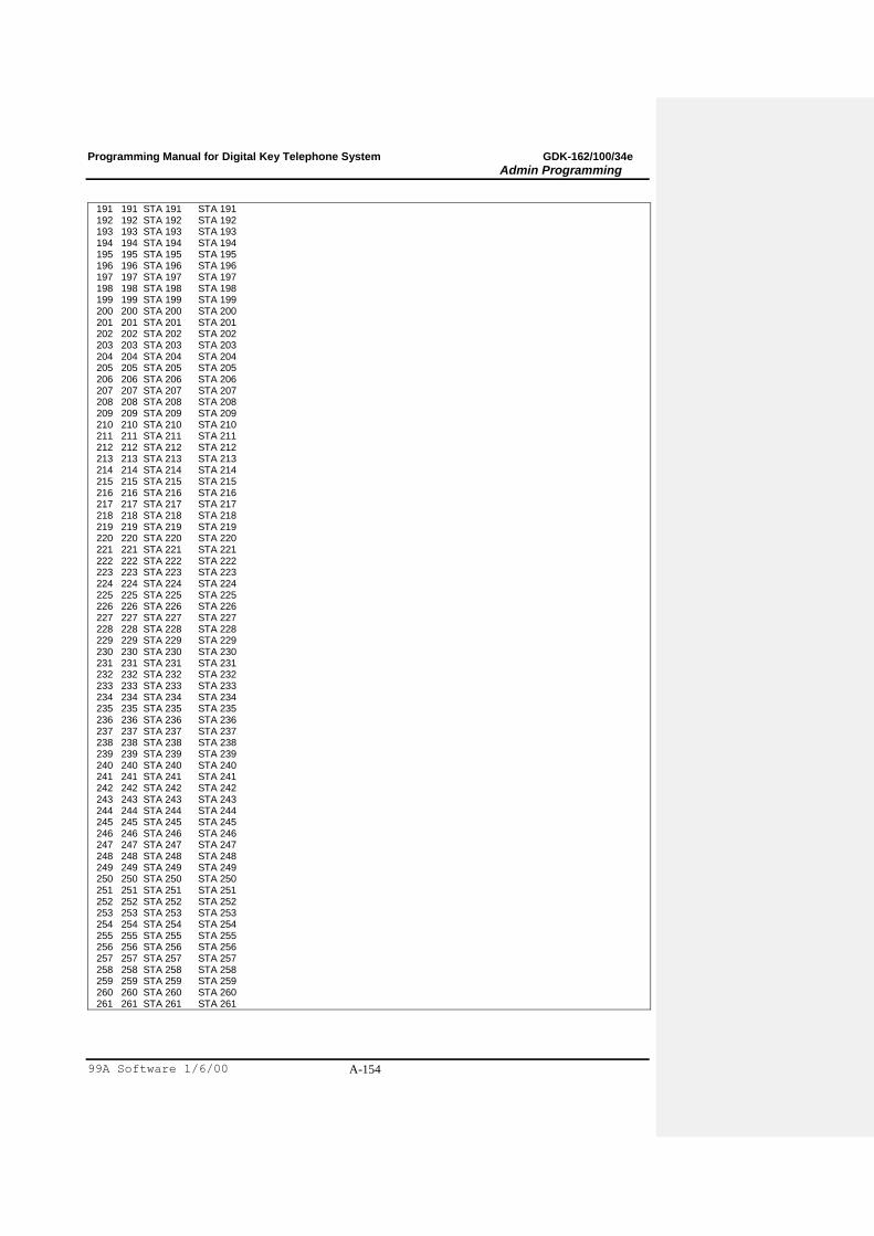
Programming Manual for Digital Key Telephone System GDK-162/100/34e
Admin Programming
99A Software 1/6/00 A-154
191 191 STA 191 STA 191 192 192 STA 192 STA 192 193 193 STA 193 STA 193 194 194 STA 194 STA 194 195 195 STA 195 STA 195 196 196 STA 196 STA 196 197 197 STA 197 STA 197 198 198 STA 198 STA 198 199 199 STA 199 STA 199 200 200 STA 200 STA 200 201 201 STA 201 STA 201 202 202 STA 202 STA 202 203 203 STA 203 STA 203 204 204 STA 204 STA 204 205 205 STA 205 STA 205 206 206 STA 206 STA 206 207 207 STA 207 STA 207 208 208 STA 208 STA 208 209 209 STA 209 STA 209 210 210 STA 210 STA 210 211 211 STA 211 STA 211 212 212 STA 212 STA 212 213 213 STA 213 STA 213 214 214 STA 214 STA 214 215 215 STA 215 STA 215 216 216 STA 216 STA 216 217 217 STA 217 STA 217 218 218 STA 218 STA 218 219 219 STA 219 STA 219 220 220 STA 220 STA 220 221 221 STA 221 STA 221 222 222 STA 222 STA 222 223 223 STA 223 STA 223 224 224 STA 224 STA 224 225 225 STA 225 STA 225 226 226 STA 226 STA 226 227 227 STA 227 STA 227 228 228 STA 228 STA 228 229 229 STA 229 STA 229 230 230 STA 230 STA 230 231 231 STA 231 STA 231 232 232 STA 232 STA 232 233 233 STA 233 STA 233 234 234 STA 234 STA 234 235 235 STA 235 STA 235 236 236 STA 236 STA 236 237 237 STA 237 STA 237 238 238 STA 238 STA 238 239 239 STA 239 STA 239 240 240 STA 240 STA 240 241 241 STA 241 STA 241 242 242 STA 242 STA 242 243 243 STA 243 STA 243 244 244 STA 244 STA 244 245 245 STA 245 STA 245 246 246 STA 246 STA 246 247 247 STA 247 STA 247 248 248 STA 248 STA 248 249 249 STA 249 STA 249 250 250 STA 250 STA 250 251 251 STA 251 STA 251 252 252 STA 252 STA 252 253 253 STA 253 STA 253 254 254 STA 254 STA 254 255 255 STA 255 STA 255 256 256 STA 256 STA 256 257 257 STA 257 STA 257 258 258 STA 258 STA 258 259 259 STA 259 STA 259 260 260 STA 260 STA 260 261 261 STA 261 STA 261

Programming Manual for Digital Key Telephone System GDK-162/100/34e
Admin Programming
99A Software 1/6/00 A-155
262 262 STA 262 STA 262 263 263 STA 263 STA 263 264 264 STA 264 STA 264 265 265 STA 265 STA 265 266 266 STA 266 STA 266 267 267 STA 267 STA 267 268 268 STA 268 STA 268 269 269 STA 269 STA 269 270 270 STA 270 STA 270 271 271 STA 271 STA 271 272 272 STA 272 STA 272 273 273 STA 273 STA 273 274 274 STA 274 STA 274 275 275 STA 275 STA 275 276 276 STA 276 STA 276 277 277 STA 277 STA 277 278 278 STA 278 STA 278 279 279 STA 279 STA 279 280 280 STA 280 STA 280 281 281 STA 281 STA 281 282 282 STA 282 STA 282 283 283 STA 283 STA 283 284 284 STA 284 STA 284 285 285 STA 285 STA 285 286 286 STA 286 STA 286 287 287 STA 287 STA 287 288 288 STA 288 STA 288 289 289 STA 289 STA 289 290 290 STA 290 STA 290 291 291 STA 291 STA 291 EMERGENCY TABLE BinNo EmerCode ----- ----------- 1 2 3 4 5 6 7 8 9 10 ------------------ ------------------------------------ MSN TABLE BinNo CO IDX MSN Telephone No ----- -- --- - --------------- 1 ** *** * 2 ** *** * 3 ** *** * 4 ** *** * 5 ** *** * 6 ** *** * 7 ** *** * 8 ** *** * 9 ** *** * 10 ** *** * 11 ** *** * 12 ** *** * 13 ** *** * 14 ** *** * 15 ** *** * 16 ** *** * 17 ** *** * 18 ** *** * 19 ** *** * 20 ** *** * 21 ** *** *
Programming Manual for Digital Key Telephone System GDK-162/100/34e
Admin Programming
99A Software 1/6/00 A-156
22 ** *** * 23 ** *** * 24 ** *** * 25 ** *** * 26 ** *** * 27 ** *** * 28 ** *** * 29 ** *** * 30 ** *** * 31 ** *** * 32 ** *** * 33 ** *** * 34 ** *** * 35 ** *** * 36 ** *** * 37 ** *** * 38 ** *** * 39 ** *** * 40 ** *** * 41 ** *** * 42 ** *** * 43 ** *** * 44 ** *** * 45 ** *** * 46 ** *** * 47 ** *** * 48 ** *** * 49 ** *** * 50 ** *** * 51 ** *** * 52 ** *** * 53 ** *** * 54 ** *** * 55 ** *** * 56 ** *** * 57 ** *** * 58 ** *** * 59 ** *** * 60 ** *** * 61 ** *** * 62 ** *** * 63 ** *** * 64 ** *** * 65 ** *** * 66 ** *** * 67 ** *** * 68 ** *** * 69 ** *** * 70 ** *** * 71 ** *** * 72 ** *** * 73 ** *** * 74 ** *** * 75 ** *** * 76 ** *** * 77 ** *** * 78 ** *** * 79 ** *** * 80 ** *** * 81 ** *** * 82 ** *** * 83 ** *** * 84 ** *** * 85 ** *** * 86 ** *** * 87 ** *** * 88 ** *** * 89 ** *** * 90 ** *** * 91 ** *** * 92 ** *** *

Programming Manual for Digital Key Telephone System GDK-162/100/34e
Admin Programming
99A Software 1/6/00 A-157
93 ** *** * 94 ** *** * 95 ** *** * 96 ** *** * 97 ** *** * 98 ** *** * 99 ** *** * 100 ** *** * 101 ** *** * 102 ** *** * 103 ** *** * 104 ** *** * 105 ** *** * 106 ** *** * 107 ** *** * 108 ** *** * 109 ** *** * 110 ** *** * 111 ** *** * 112 ** *** * 113 ** *** * 114 ** *** * 115 ** *** * 116 ** *** * 117 ** *** * 118 ** *** * 119 ** *** * 120 ** *** * 121 ** *** * 122 ** *** * 123 ** *** * 124 ** *** * 125 ** *** * 126 ** *** * 127 ** *** * 128 ** *** * ------------------------------------ <<SLT assigned with MOH>> MOH5 MOH6 MOH7 MOH8 MOH9 ----------------------------- *** *** *** *** *** <<PORT Usage>> SMDR1 ADMIN SMDI SMDR2 TRACE RS-232 RS-232 RS-232 RS-232 RS-232 ------------------------------------------
Toll Tables B T N 7
EXCEPTION TABLES ---------------- ALLOW TABLE 1=E 2=E 3=E 4=E 5=E 6=E 7=E 8=E 9=E 10=E 11=E 12=E 13=E 14=E 15=E 16=E 17=E 18=E 19=E 20=E DENY TABLE A 1=E 2=E 3=E 4=E 5=E 6=E 7=E 8=E 9=E 10=E ALLOW TABLE B 1=E 2=E 3=E 4=E 5=E 6=E 7=E 8=E 9=E 10=E 11=E 12=E 13=E 14=E 15=E 16=E
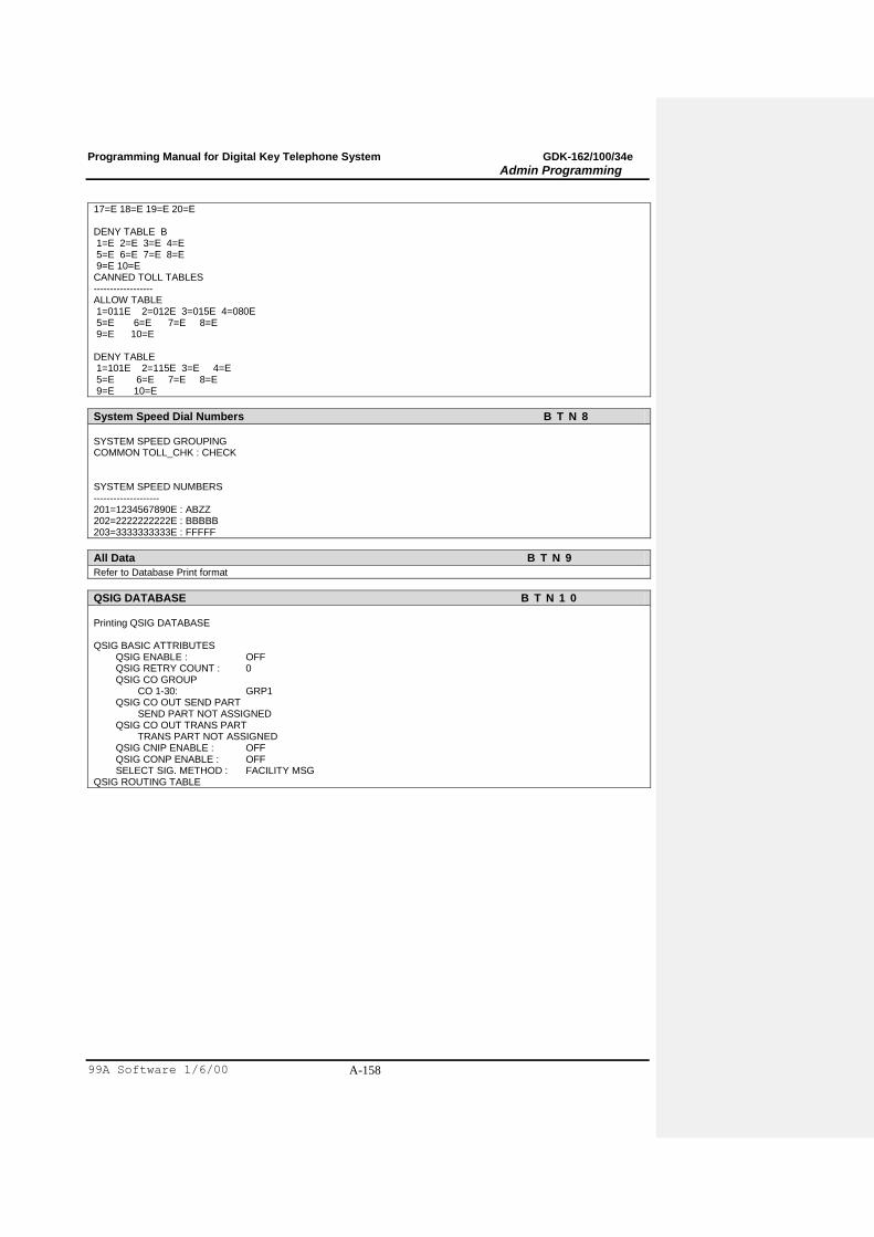
Programming Manual for Digital Key Telephone System GDK-162/100/34e
Admin Programming
99A Software 1/6/00 A-158
17=E 18=E 19=E 20=E DENY TABLE B 1=E 2=E 3=E 4=E 5=E 6=E 7=E 8=E 9=E 10=E CANNED TOLL TABLES ------------------ ALLOW TABLE 1=011E 2=012E 3=015E 4=080E 5=E 6=E 7=E 8=E 9=E 10=E DENY TABLE 1=101E 2=115E 3=E 4=E 5=E 6=E 7=E 8=E 9=E 10=E
System Speed Dial Numbers B T N 8
SYSTEM SPEED GROUPING COMMON TOLL_CHK : CHECK SYSTEM SPEED NUMBERS -------------------- 201=1234567890E : ABZZ 202=2222222222E : BBBBB 203=3333333333E : FFFFF
All Data B T N 9
Refer to Database Print format
QSIG DATABASE B T N 1 0
Printing QSIG DATABASE QSIG BASIC ATTRIBUTES QSIG ENABLE : OFF QSIG RETRY COUNT : 0 QSIG CO GROUP CO 1-30: GRP1 QSIG CO OUT SEND PART SEND PART NOT ASSIGNED QSIG CO OUT TRANS PART TRANS PART NOT ASSIGNED QSIG CNIP ENABLE : OFF QSIG CONP ENABLE : OFF SELECT SIG. METHOD : FACILITY MSG QSIG ROUTING TABLE