digital imaging radar-setup manual
TRANSCRIPT

Introduction This manual provides some instructions and hints for setting up the Si-TEX radar that are not contained in their instruction manual, and which pertain to operation and integration with the ISR data acquisition system. Any suggestions as to improvement of this manual are appreciated.
General Background The ISR Digital Imaging Radar (DIR) system consists of the following components: 1. A Si-TEX radar antenna, pedestal, and MDS control box that interfaces to the controlling laptop computer. The ‘Ethernet’ version of the radar is provided (vs. the USB interface), which allows double-speed rotation rates with periods of 1.25-sec typical. This allows ocean wave frequency spectra coverage up to nearly 0.4Hz in wave frequency, vs. the 0.2 Hz limitation using normal rotation speed typical of most other marine radars. 2. A laptop computer running under Windows XP, with the P-Sea radar control software pre-installed and tested. Charger should always be plugged in and charging the computer during radar operation. For remote sites where battery and/or solar/wind power sources are used, the laptop can be put into a sleep mode to conserve energy, after the radar is up and running. 3. A 28-volt 10-amp DC power supply for the radar, running on 110 volts AC input. For foreign operation at other than 110-volts AC, any alternative that can provide 10 amps of current at 28 volts will suffice. 28 volts is standard shipboard DC power, but the radar will run over the entire range of 10-48 volts, with current requirements determined by power draw (P=I*V), so halving the DC voltage source will double the current draw. (See Koden manual for more detail.)
4. An ISR rack-mountable Data Acquisition Computer (DAC) running under Windows XP, with a Quadrec data acquisition card with on-board processing capabilities.
Each of these is discussed in some detail, with regard to their setup and operation.
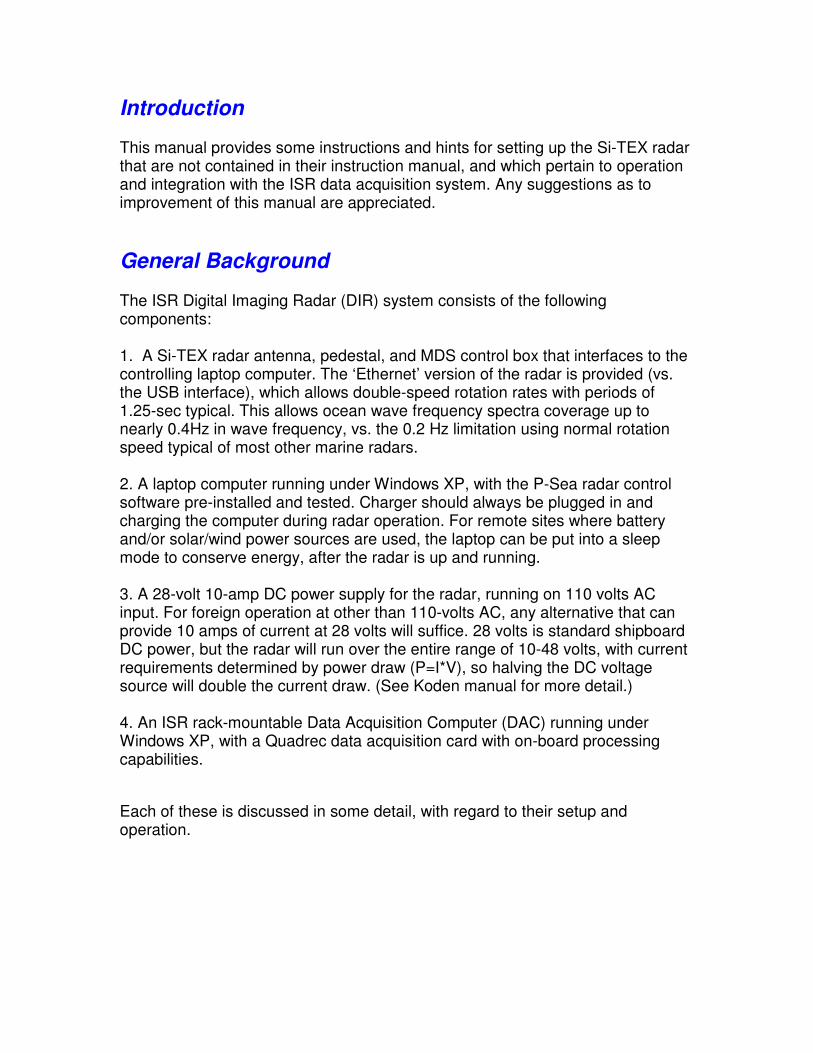
1. Si-TEX Radar Installation The Si-TEX radar is described in their radar manual contained in the PDF file provided. The important installation instruction relating to the operation for coastal or shipboard radar operation in the alignment of the pedestal relative to the area of interest. This is important because this alignment will determine the starting azimuth of the data acquisition system. The pedestal provides a signal pulse once per rotation, known as the “Heading Pulse”. This signal provides one of the inputs to the data acquisition system and is labeled as such on the MDS box and DAC input list. A copy of the last figure of the Si-TEX setup manual is shown below in Figure 1-1. Figure 1-1. Drawing of antennas for DIR X.4, -6, and -.9 radars, showing bulbous cap on the right image, facing to the left. The smaller opposite end contains the heading pulse magnet and should be pointed in the direction of desired starting azimuth for each rotation of the antenna, typically to the left at a coastal site when facing the water Mount forward face of antenna on rotating plate, in the same direction as the two arrows embossed on the surface of this plate, and insert bolts and tighten.. If one is operating at a coastal site, then typically one aligns the non-bulbous cap end of the radar pedestal of the order of 5 deg. or so landward of the coastline or desired starting angle. Final alignment relative to north is selectable in data
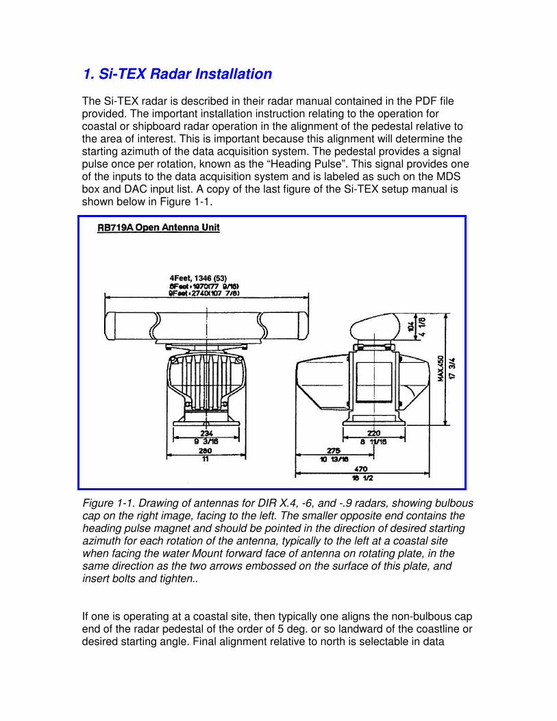
processing later. Figure 1-2 shows a radar sum image showing the coast line to the right, and about 5 degrees of land coverage before the coast interception. Figure 1-2. Radar sum-image collected at the USACE Field Research Facility, Duck, NC, with the radar set about 3.5 deg inland from the coast. Strongest red echoes are houses north of FRF property. The radar was set by eye to assure a start angle inland of the coastline. To set the alignment of the pier at 90 deg in the image, a start angle in TRANS.PAR of 356.5 was used, where 360-deg is assigned to the positive x-axis to the right (See RIPS manual for details on parameter files.) A start angle of 266.5 deg would have set the pier lying facing to the right in the image, rotated counter-clockwise by 90 deg. As the FRF coastline perpendicular is actually 70 deg relative to north, a value of 336.5 deg for the start angle would be required to achieve this true bearing. Note that all processing outputs of azimuthal values, such as wave direction, are determined by this starting angle value in TRANS.PAR. In summary, always align the bulbous end of the radar so that some land will appear in the image in order to reference the coastline onset.
2.Si-TEX Cable Installation The customer is responsible for installation of the radar cable that comes with the radar, and minimal instructions are provided by Koden. The cable has two plastic connectors and a ground wire at the radar end. The simplest way to do the installation is to remove the bulbous end cap, and remove the pair of nuts holding a plate covering the rubber water-proofing grommet from the base of the pedestal.
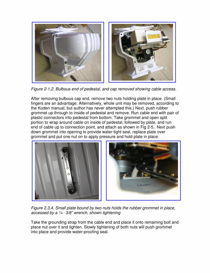
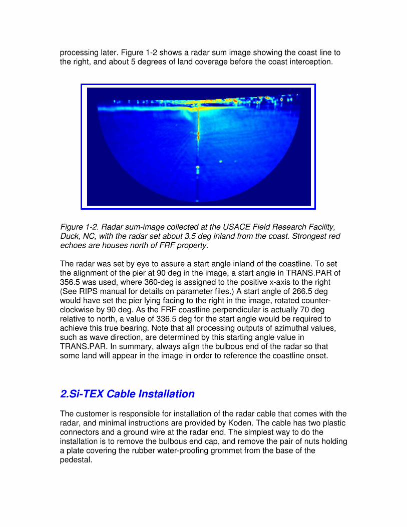
Figure 2-1,2. Bulbous end of pedestal, and cap removed showing cable access. After removing bulbous cap end, remove two nuts holding plate in place. (Small fingers are an advantage. Alternatively, whole unit may be removed, according to the Koden manual, but author has never attempted this.) Next, push rubber grommet up through to inside of pedestal and remove. Run cable end with pair of plastic connectors into pedestal from bottom. Take grommet and open split portion to wrap around cable on inside of pedestal, followed by plate, and run end of cable up to connection point, and attach as shown in Fig 2-5.. Next push down grommet into opening to provide water-tight seal, replace plate over grommet and put one nut on to apply pressure and hold plate in place. Figure 2.3,4. Small plate bound by two nuts holds the rubber grommet in place, accessed by a ¼ - 3/8” wrench, shown tightening Take the grounding strap from the cable end and place it onto remaining bolt and place nut over it and tighten. Slowly tightening of both nuts will push grommet into place and provide water-proofing seal.
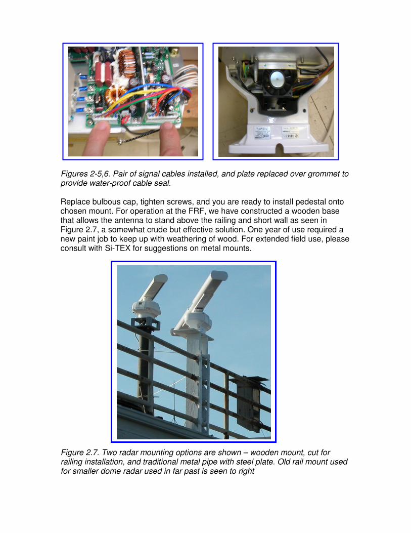
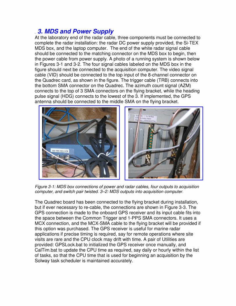
Figures 2-5,6. Pair of signal cables installed, and plate replaced over grommet to provide water-proof cable seal. Replace bulbous cap, tighten screws, and you are ready to install pedestal onto chosen mount. For operation at the FRF, we have constructed a wooden base that allows the antenna to stand above the railing and short wall as seen in Figure 2.7, a somewhat crude but effective solution. One year of use required a new paint job to keep up with weathering of wood. For extended field use, please consult with Si-TEX for suggestions on metal mounts. Figure 2.7. Two radar mounting options are shown – wooden mount, cut for railing installation, and traditional metal pipe with steel plate. Old rail mount used for smaller dome radar used in far past is seen to right
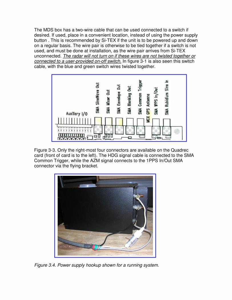
. 3. MDS and Power Supply At the laboratory end of the radar cable, three components must be connected to complete the radar installation: the radar DC power supply provided, the Si-TEX MDS box, and the laptop computer. The end of the white radar signal cable should be connected to the matching connector on the MDS box to begin, then the power cable from power supply. A photo of a running system is shown below in Figures 3-1 and 3-2. The four signal cables labeled on the MDS box in the figure should next be connected to the acquisition computer. The video signal cable (VID) should be connected to the top input of the 8-channel connector on the Quadrec card, as shown in the figure. The trigger cable (TRB) connects into the bottom SMA connector on the Quadrec. The azimuth count signal (AZM) connects to the top of 3 SMA connectors on the flying bracket, while the heading pulse signal (HDG) connects to the lowest of the 3. If implemented, the GPS antenna should be connected to the middle SMA on the flying bracket. Figure 3-1: MDS box connections of power and radar cables, four outputs to acquisition computer, and switch pair twisted. 3–2: MDS outputs into acquisition computer.
The Quadrec board has been connected to the flying bracket during installation, but if ever necessary to re-cable, the connections are shown in Figure 3-3. The GPS connection is made to the onboard GPS receiver and its input cable fits into the space between the Common Trigger and 1-PPS SMA connectors. It uses a MCX connection, and the MCX-SMA cable to the flying bracket will be provided if this option was purchased. The GPS receiver is useful for marine radar applications if precise timing is required, say for remote operations where site visits are rare and the CPU clock may drift with time. A pair of Utilities are provided: GPSLock.bat to initialized the GPS receiver once manually, and CalTim.bat to update the CPU time as required, say daily or hourly within the list of tasks, so that the CPU time that is used for beginning an acquisition by the Solway task scheduler is maintained accurately.
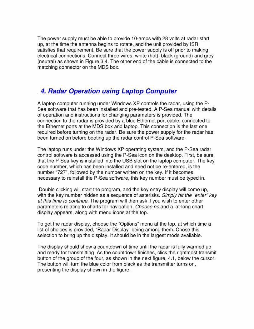
The MDS box has a two-wire cable that can be used connected to a switch if desired. If used, place in a convenient location, instead of using the power supply button . This is recommended by Si-TEX if the unit is to be powered up and down on a regular basis. The wire pair is otherwise to be tied together if a switch is not used, and must be done at installation, as the wire pair arrives from Si-TEX unconnected. The radar will not turn on if these wires are not twisted together or connected to a user-provided on-off switch. In figure 3-1 is also seen this switch cable, with the blue and green switch wires twisted together. Figure 3-3. Only the right-most four connectors are available on the Quadrec card (front of card is to the left). The HDG signal cable is connected to the SMA Common Trigger, while the AZM signal connects to the 1PPS In/Out SMA connector via the flying bracket. Figure 3.4. Power supply hookup shown for a running system.
The power supply must be able to provide 10-amps with 28 volts at radar start up, at the time the antenna begins to rotate, and the unit provided by ISR satisfies that requirement. Be sure that the power supply is off prior to making electrical connections. Connect three wires, white (hot), black (ground) and grey (neutral) as shown in Figure 3.4. The other end of the cable is connected to the matching connector on the MDS box.
. 4. Radar Operation using Laptop Computer A laptop computer running under Windows XP controls the radar, using the P-Sea software that has been installed and pre-tested. A P-Sea manual with details of operation and instructions for changing parameters is provided. The connection to the radar is provided by a blue Ethernet port cable, connected to the Ethernet ports at the MDS box and laptop. This connection is the last one required before turning on the radar. Be sure the power supply for the radar has been turned on before booting up the radar control P-Sea software. The laptop runs under the Windows XP operating system, and the P-Sea radar control software is accessed using the P-Sea icon on the desktop. First, be sure that the P-Sea key is installed into the USB slot on the laptop computer. The key code number, which has been installed and need not be re-entered, is the number “727”, followed by the number written on the key. If it becomes necessary to reinstall the P-Sea software, this key number must be typed in. Double clicking will start the program, and the key entry display will come up, with the key number hidden as a sequence of asterisks. Simply hit the “enter” key at this time to continue. The program will then ask if you wish to enter other parameters relating to charts for navigation. Choose no and a lat-long chart display appears, along with menu icons at the top. To get the radar display, choose the “Options” menu at the top, at which time a list of choices is provided, “Radar Display” being among them. Chose this selection to bring up the display. It should be in the largest mode available. The display should show a countdown of time until the radar is fully warmed up and ready for transmitting. As the countdown finishes, click the rightmost transmit button of the group of the four, as shown in the next figure, 4.1, below the cursor. The button will turn the blue color from black as the transmitter turns on, presenting the display shown in the figure.
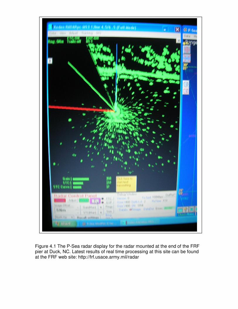
Figure 4.1 The P-Sea radar display for the radar mounted at the end of the FRF pier at Duck, NC. Latest results of real time processing at this site can be found at the FRF web site: http://frf.usace.army.mil/radar