digital actuator technology - technology resources : … inl is a u.s. department of energy national...
TRANSCRIPT
The INL is a U.S. Department of Energy National Laboratory operated by Battelle Energy Alliance
INL/EXT-14-33132
Digital Actuator
Technology
Ted Quinn, Jerry Mauck, Richard Bockhorst; Technology Resources
Ken Thomas; Idaho National Laboratory
September 2014

DISCLAIMER
This information was prepared as an account of work sponsored by
an agency of the U.S. Government. Neither the U.S. Government
nor any agency thereof, nor any of their employees, makes any
warranty, expressed or implied, or assumes any legal liability or
responsibility for the accuracy, completeness, or usefulness, of any
information, apparatus, product, or process disclosed, or represents
that its use would not infringe privately owned rights. References
herein to any specific commercial product, process, or service by
trade name, trade mark, manufacturer, or otherwise, does not
necessarily constitute or imply its endorsement, recommendation, or
favoring by the U.S. Government or any agency thereof. The views
and opinions of authors expressed herein do not necessarily state
or reflect those of the U.S. Government or any agency thereof.

INL/EXT-14-33132
Digital Actuator Technology
Ted Quinn, Jerry Mauck, Richard Bockhorst; Technology Resources
Ken Thomas; Idaho National Laboratory
September 2014
Idaho National Laboratory Idaho Falls, Idaho 83415
http://www.inl.gov
Prepared for the U.S. Department of Energy Office of Nuclear Energy
Under DOE Idaho Operations Office Contract DE-AC07-05ID14517

iii
The U.S. Department of Energy (DOE) Office of Nuclear Energy (NE) established the Advanced Sensors and Instrumentation (ASI) technology area under the Nuclear Energy Enabling Technologies (NEET) Program to coordinate the instrumentation and controls (I&C) research across DOE-NE and to identify and lead efforts to address common needs. As part of the NEET ASI research program, the Digital Technology Qualification project was established based on collaboration between Oak Ridge National Laboratory (ANL) and Idaho National Laboratory (INL). This report was prepared under Work Package CT-13IN070307.

iv
EXECUTIVE SUMMARY
The nuclear industry has been slow to incorporate digital actuator technology into nuclear
plant designs for several reasons, including:
The high cost of design change modifications to implement them, versus simply
replacing them with like-for-like technology when the components fail.
Digital technology qualification issues, particularly in safety related applications that
are susceptible to software common cause failure. This is a concern both for current
operating plants as well as new builds.
General familiarity and comfort with the existing analog technology on the part of the
nuclear plant engineering staff, in spite of the superior performance and reduced
maintenance costs of the digital replacements.
At the same time, the nuclear industry is under significant cost pressure in the electric
marketplace due to the abundance of gas generation. The industry would benefit by investment
in new technologies that could lower future operating costs while addressing current
obsolescence and reliability issues of the current technologies. However, the industry has been
unable to formulate the business cases to take advantage of these labor savings and production
reliability improvements.
This report presents the benefits digital actuator technology for four types of actuators that
account for the vast majority of control applications in a nuclear power plant: pneumatic control,
hydraulic control, motor control, and variable frequency drives. The report describes the
common failure modes of the analog actuators as confirmed by actual component failure
records from an industry failure data base.
The report discusses the benefits of digital actuators, which are generally found in two main
areas. First, the digital technology offers superior operational performance over its analog
counterparts, in terms of accuracy, reliability, and maintainability. Also, actuator setup is
considerably easier with the digital technology. Second, the cost of maintaining the digital
actuators is lower due to simplicity of operation (circuit boards vs. mechanical parts) and on-
board diagnostics that greatly improve troubleshooting and repair.
Notwithstanding the benefits of digital actuators, there are certain qualification and licensing
challenges that are inherent with digital technology, and these are described in the report. One
major qualification impediment for digital sensor implementation is software common cause
failure (SCCF). A typical analysis for SCCF, in the form of a Nuclear Regulatory Commission
(NRC) regulatory submittal, is presented to demonstrate the difficulty in addressing SCCF for
nuclear safety-related designs. It also addresses what options exist to mitigate the SCCF
concerns.
The report concludes with a summary of benefits to be gained and challenges to be
addressed in pursuing the wide-scale application of digital actuator technology. In particular, it
highlights the need for new approaches in digital technology qualification over the only currently-
accepted approach of presenting a coping analysis for an assumed SCCF.

v

vi
CONTENTS
ACRONYMS............................................................................................................... ix
1. Introduction……………………………………………………………………………... 1
1.1 Purpose……………………………………………………………………………. 1
1.2 Scope………………………………………………………………………………. 3
2. Background…………………………………………………………………………...... 4
2.1 Why Digital Actuator Technology is Needed…………………………………… 4
2.2 Barriers to Digital Implementation in Nuclear Power Plants…………………. 4
2.3 Current State of Digital Actuator Implementation……………………………… 7
3. Actuator Technologies………………………………………………………………… 7
3.1 Pneumatic Valve and Damper Control…………………………………………. 8
3.1.1 Analog Pneumatic Control………………………………………………… 8
3.1.2 Instrument Air Systems……………………………………………………. 10
3.1.3 Digital Pneumatic Control…………………………………………………. 12
3.1.4 Industry Experience………………………………………………………... 14
3.2 Hydraulic Actuators……………………………………………………………….. 15
3.2.1 Analog Hydraulic Actuators……………………………………………….. 15
3.2.2 Hydraulic Oil Supply System……………………………………………… 16
3.2.3 Digital Replacements for Hydraulic Actuators………………………….. 17
3.2.4 Industry Experience……………………………………………………….. 19
3.3 Motor Control Centers……………………………………………………………. 20
3.3.1 Motor Control Center Description……………………………………….... 20
3.3.2 Digital Technology for Motor Control Centers…………………………... 22
3.3.3 Industry Experience………………………………………………………... 22
3.4 Variable Frequency Motor Drives……………………………………………….. 23
3.4.1 Variable Frequency Motor Drive Description……………………………. 23
3.4.2 Digital Technology for Variable Frequency Drives……………………… 25
3.4.3 Industry Experience………………………………………………………... 26

vii
4. Actuator Reliability, Availability, and Maintainability……………………………….. 28
4.1 Importance of Actuator Reliability………………………………………………. 29
4.2 Example Reliability Calculation – Valve Actuator…………………………….. 30
4.3 Availability…………………………………………………………………………. 34
4.4 Maintainability…………………………………………………………………….. 36
5. Qualification Considerations………………………………………………………….. 37
5.1 Software……………………………………………………………………………. 38
5.2 Environmental, Seismic, and Electromagnetic Compatibility Qualification…. 38
5.3 Software Common Cause Failure………………………………………………. 39
5.3.1 D3 Regulatory Criteria…………………………………………………….. 41
5.3.2 D3 Analysis Process for Digital Actuator………………………………… 43
5.3.3 Analysis for SCCF within Non-Safety Related Actuators……………… 46
5.4 Communications………………………………………………………………….. 47
5.5 Cyber Security…………………………………………………………………….. 48
6. Licensing Considerations……………………………………………………………… 49
6.1 Nuclear Plant Modifications under Licensee Control…………………………. 49
6.2 Nuclear Plant Modifications under NRC License Amendment………………. 51
6.3 Improvements in Plant Technical Specifications………………………………. 51
6.4 Certification of New Nuclear Plant Designs……………………………………. 52
6.5 Summary of Qualification and Licensing Considerations…………………….. 53
7. Summary………………………………………………………………………………... 54
8. References……………………………………………………………………………… 57
Appendix A Common Actuator Failure Modes…………………………………………. 61
Appendix B Example D3 Evaluation…………………………………………………… 63
viii
FIGURES
Figure 1 Pneumatic Valve and Damper Circuit………………………………………… 8
Figure 2 Typical Control Valve Air Supply Arrangement……………………………… 9
Figure 3 Typical Instrument Air Supply System……………………………………….. 10
Figure 4 Example Digital Valve Positioner Block Diagram…………………………… 13
Figure 5 Exlar Roller Screw Mechanism for Linear Motion…………………………… 18
Figure 6 Variable Frequency Drive……………………………………………………… 24
Figure 7 VFDs in Operation at Millstone………………………………………………… 26
Figure 8 BWR Depicting Recirculation Pump…………………………………………... 27
TABLES
Table 1 Pneumatic Control Valve Failure Modes………………………………………. 11
Table 2 Installed Base of VFDs in Nuclear Plants in the U.S………………………… 28
ix
ACRONYMS
AFS Auxiliary Feedwater System
AFW Auxiliary Feedwater
ANS American Nuclear Society
AOO Anticipated Operational Occurrence
ATWS Anticipated Transient Without Scram
BTP Branch Technical Position
BWR Boiling Water Reactor
CCF Common Cause Failure
CCP Centrifugal Charging Pump
CCW Component Cooling Water
CDA Critical Digital Assets
CFA Cubic feet per minute
COL Combined Operating License
CW Circulating Water
D3 Diversity and Defense-in-Depth
DAS Diverse Actuation Systems
DAC Design Acceptance Criteria
DBA Design Basis Accident
DCD Design Control Document
DCS Digital Control System
DNB Departure from Nuclear Boiling
DNBR Departure from Nuclear Boiling Ratio
ECCS Emergency Core Cooling System
EHC Electrohydraulic Control
EMC Electromagnetic Compatibility
EMI/RFI Electromagnetic and Radio Frequency Interface
EOP Emergency Operating Procedure
EPRI Electric Power Research Institute
ESD Electro Static Discharge
ESF Engineered Safety Function
ESFAS Engineered Safety Function Actuation Systems

x
°F Degrees Fahrenheit
FWCS Feedwater Control System
FMEA Failure Modes and Effects Analysis
HFE Human Factors Engineering
HVAC Heating, Ventilation, and Air Conditioning
I&C Instrumentation and Control
IEEE Institute of Electrical and Electronics Engineers
INPO Institute of Nuclear Power Operations
I/P Current to Pressure Converter
ISA International Society of Automation
ISG Interim Staff Guidance
ITAAC Inspections, Tests, Analysis, and Acceptance Criteria
LBLOCA Large Break LOCA
LOCA Loss of Coolant Accident
LVDT Linear variable differential transformer
mA Milliamp
MCC Motor Control Center
MCCB Molded case circuit breaker
MSLB Main Steam Line Break
MSR Moisture separator reheater
MSSV Main Steam Safety Valve
MTBF Mean-Time-Between-Failure
MTC Moderator Temperature Coefficient
MTTR Mean-Time-To-Repair
MW Megawattt
NEI Nuclear Energy Institute
NGNP Next Generation Nuclear Power Plant
NPP Nuclear Power Plant
NRC Nuclear Regulatory Commission
O&M Operation and Maintenance
PFD Probability of Failure on Demand
PIE Postulated Initiating Event
PLC Programmable Logic Controller
PM Preventive maintenance

xi
PRA Probabilistic Risk Assessment
PSIA Pounds per square inch absolute
PWR Pressurized Water Reactor
RCA Rod Control Assembly
RCS Reactor Coolant System
RIS Regulatory Information Summary
RPS Reactor Protection System
RRS Reactor Recirculation System
RTS Reactor Trip System
SAR Safety Analysis Report
SER Safety Evaluation Report
SFCP Surveillance Frequency Control Program
SG Steam Generator
SIS Safety Injection System
SMR Small Modular Reactors
SSC System, Structure, Component
STG Steam Generator Tube Rupture
SCCF Software Common Cause Failure
TI Test Interval
UFSAR Updated Final Safety Analysis Report
VSD Variable Speed Drive

1
1.0 Introduction
1.1 Purpose
This report presents the benefits of using digital actuators in nuclear power plants for
component positioning and operation, and describes the challenges in digital technology
qualification that are impeding their rate of adoption. The report builds on two previous reports
that dealt with sensors and logic processors. These reports are:
1. Digital Technology Qualification (INL/EXT-12-27215) [1]
2. Digital Sensor Technology (INL/EXT-13-29750) [2]
A major theme of these reports is the identification of barriers in the use of digital in an end-
to-end comprehensive manner or, in other words, from sensor to control system to actuator.
This is an important concept in the achievement of the full benefit of digital technology with its
superior performance and maintainability characteristics. Too often today, nuclear plant
designers implement a modern digital control system capable of high precision control, but then
couple it with less-accurate analog sensors and actuators. This effectively negates the benefits
of the digital control system in that the analog components tend to dominate the overall system
accuracy and reliability.
There are many proven digital actuator product offerings available today and more are being
developed. The process industry has made considerable use of them and has proven the
benefits in actual field experience. In addition, digital actuators have been used very
successfully in conventional power generation. These other industries typically operate on
smaller financial margins than nuclear generation, and so the business cases for their upgrades
must be sound. Nevertheless, they have been able to incorporate these digital actuator
technologies in both new existing facilities. It is also recognized that the qualification
requirements for these other industries might be less stringent than that for nuclear application,
although it can be argued that process industries have many comparable safety-critical designs.
In any event, the nuclear industry has been slow to incorporate digital actuator technology
into nuclear plant designs for several reasons, including:
The high cost of design change modifications to implement them, versus simply
replacing them with like-for-like technology when the components fail.
Digital technology qualification issues, particularly in safety related applications that
are susceptible to software common cause failure. This is a concern both for current
operating plants as well as new builds.
General familiarity and comfort with the existing analog technology on the part of the
nuclear plant engineering staff, in spite of the superior performance and reduced
maintenance costs of the digital replacements.
In nuclear plant design, many of the large and more expensive components are intended to
last for the life of the station, and so the opportunity to replace them occurs only in the case of a
premature failure. However, this is not true for actuators. They typically do not last the life of
the station and are periodically replaced due to reliability concerns and design specification
changes (e.g. more closing force for a valve actuator).

2
The replacement opportunity for these actuators represents a decision point in whether to
invest in more modern technology that would provide superior operational and maintenance
benefits. However, the legacy analog technology remains available at least for the foreseeable
future, although this might not always be true. Therefore, nuclear utilities today have the
option to replace actuators with like-for-like replacements that avoid design change modification
costs and other direct costs such as revising plant testing and maintenance procedures, training
modules, etc.
To help the nuclear industry better understand the opportunity represented by digital
actuator technology, the report discusses the benefits of digital actuators, which are generally
found in two main areas. First, digital technology offers superior operational performance over
its analog counterparts, in terms of accuracy, reliability, and maintainability. Also, actuator
setup is considerably easier with the digital technology. Second, the cost of maintaining the
digital actuators is lower due to simplicity of operation (circuit boards vs. mechanical parts) and
on-board diagnostics that greatly improve troubleshooting and repair.
Yet, the application of digital technology has been problematic for the nuclear industry, due
to qualification and regulatory issues. With some notable exceptions, the result has been a
continuing reluctance to undertake the risks and uncertainties of implementing digital actuator
technology when replacement opportunities present themselves. Rather, utilities would typically
prefer to accept the performance limitations of the legacy analog actuator technologies in order
to avoid potential impacts to project costs and schedules.
To challenge the conventional thinking, this report presents the benefits of digital actuator
technology as significant in terms of plant performance and reduced operating cost, and
proposes that it is worthwhile to address the barriers currently holding back the widespread
implementation of this technology.
In regard to the benefits, this project investigates the advantages of digital actuator
technology as it improves performance in the areas of accuracy, reliability, and maintainability.
It describes the performance improvement with the digital actuators and asserts that it is very
much in the interest of the commercial nuclear industry to find an acceptable solution to the
issue of SCCF for digital actuators.
The barriers to implementation are the subject of a related Oak Ridge National Laboratory
project for which the goal is to resolve the impediments to qualification of digital technology for
nuclear power application to enable more extensive utilization of modern equipment in the full
range of I&C systems at nuclear power plants. [3] More specifically, the project is developing an
objective, scientific basis for determining necessary and sufficient mitigation of software
common cause failure vulnerabilities.
Together, these projects will demonstrate the application of equipment, strategies, and
methodologies to enable more extensive digital technology usage.

3
1.2 Scope
The scope of this report focuses on major component actuators that are typically found in all
control systems of a nuclear power plant. These are actuators are pneumatic control, hydraulic
control, motor control, and variable frequency drives. These types of actuators represent the
majority of plant applications, covering such components as valves, dampers, motors (and other
electrical loads), and pumps.
These actuators are found in all types of nuclear power plants. This includes the current
U.S. light water reactor operating fleet, the new builds that are in the licensing and construction
process now, small modular reactors (SMRs), and the next generation nuclear plants (NGNP).
Even though there are a variety of reactor technologies, the underlying plant systems still
consist of the same types of major active components – valves, pumps, dampers, motors, etc.
The requirements for actuators for these types of active components remain the same across all
of the reactor technologies. In some cases, their qualification criteria differ.
The scope of the qualification and licensing considerations is that set of concerns specific to
digital regardless of reactor technology and plant type. These include both the conventional
qualifications such as seismic, environmental, and EMC, and the qualification considerations
peculiar to digital technology such as cyber security and software common cause failure. In the
licensing area, the scope includes the various regulatory processes that are applicable both in
general and in particular to digital technology implementation in nuclear power plants.
The organization of the major sections of the report is as follows:
Section 2 Provides background information on why digital actuator technology is beneficial,
what the barriers are in implementation, and the current state of digital actuator
usage.
Section 3 Provides an overview of current state analog actuator technologies and the
particular performance limitations that they have.
Section 4 Describes reliability, availability, and maintainability comparisons of analog vs.
digital actuator technologies.
Section 5 Describes certain qualification considerations that are must be addressed for
digital actuators to be used in critical areas of nuclear power plants.
Section 6 Describes certain licensing considerations that are somewhat of a challenge with
digital technology and that must be addressed in order to take advantage of
digital actuators in nuclear power plant (NPP) designs.
Section 7 Presents the conclusions of the project and describes future efforts needed to for
the wide-spread implementation of digital actuators.

4
2.0 Background
2.1 Why Digital Actuator Technology is Needed
Digital actuator technology has been available to the nuclear industry for many years.
During this time, other industries have made extensive use of it to improve the reliability of their
operations and to lower costs. In the face of competitive pressure, these other industries have
been able to derive positive business cases to invest in these technologies. In fact, such
technologies have proven to be a competitive advantage in managing production costs.
Today, the nuclear industry is facing unprecedented cost pressure. On the revenue side,
low-cost gas generation is setting market conditions that are challenging many unregulated
nuclear power plants with financial viability. Indeed, the closing of Kewaunee Nuclear Station in
2013 was due to the inability to compete in the market place [4]. This plant was operating very
well, had no major component issues, and was in good regulatory standing.
On the cost side, nuclear plants today are having to make some major investments to
increase safety margins. There is a series of mandatory plant modifications now in progress to
address issues arising from the Fukushima accident. This has come on the heels of a long
series of previous mandatory plant upgrades related to such issues as security, extensive
damage, flood protection, reactor heads, containment sumps, steam generators, and others.
Many utilities have elected to invest in plant uprates to increase the power output, and thereby
the economic value of their plants. In view of all of these mandatory and elective upgrades,
there is a pressing need to reduce operating costs so that the investments are fully recovered
and the nuclear plants are positioned for long-term operation.
A major impetus for increased use of digital actuators is that it is a means of reducing
operating costs. As discussed in Section 3.0, digital actuators offer performance and
maintainability benefits. They offer significant diagnostic and health reporting capabilities that
can also reduce plant support costs and provide earlier warning of impending failures. The
avoidance of failures that could result in costly plant shutdowns and adverse regulatory actions
is a significant indirect cost benefit.
Ironically, many plants have upgraded their plant control systems to digital, which is
evidence that they value the operational advantages of digital technology. However, for the
most part, these plants continue to use analog actuators on the output side of the digital control
systems for reasons that are described in the next section of this report. This greatly limits the
overall benefits of the modern digital control systems and leaves operating costs higher than
they otherwise would be.
2.2 Barriers to Digital Implementation in Nuclear Power Plants
One of the main barriers to widespread implementation of digital actuators is the design and
implementation costs to change an analog actuator to digital technology. The cost of a design
change modification is relatively high in the nuclear industry due to all of the processes and
documentation that must be completed to ensure that the regulatory requirements of the design
and licensing bases have been met. In addition to the cost, the number of qualified engineering

5
staff is also a limitation. For this reason, most nuclear plants limit the number of modifications
that they are willing to take on in a given period of time.
Moreover, the budgets that are allocated to modifications are mostly consumed by
mandatory modifications driven by regulatory requirements or deteriorating performance of
important plant equipment. In other words, continued operations are in some way threatened.
This typically leaves little budget for elective modifications whose merit is based on future cost
savings. As long as the plants have an option to replace failing components such as actuators
with either the same or like technology, this will be an attractive option. The plants have an
“equivalent change” process (meaning the design and licensing bases are not changed) and
they can execute this process for a fraction of the cost of a design change.
In order to overcome this barrier, nuclear plants will have to derive business cases that
justify the increased modification costs in order to lower the cost of future operations. This will
require a thorough examination of the benefits this technology can have across many plant
organizations and thereby produce an aggregate benefit analysis based on positive impacts on
many plant work activities over the remaining (including extended) life of the plant.
As previously mentioned, the industry has entered an era when comprehensive focus on
reducing operating costs is likely to become an imperative. Much of this is driven by external
factors such as the price of gas generation and whether expensive regulatory-driven upgrades
continue at the present rate. However, digital actuator technology is poised to be a part of the
solution, along with many other technology and process improvements that are available. The
benefits of this technology as presented in Sections 3.0 and 4.0 will constitute the basis of such
a business case.
A second important barrier that must be overcome is the issue of digital technology
qualification. Because digital involves electronic components and software, there are
qualification requirements that go beyond those for their analog predecessors. Some of these
are based on the plant physical environment, such as seismic, environmental (temperature,
pressure, high energy spray impingement, radiation), and electromagnetic interference.
Electronic components tend to be more sensitive to these phenomena compared to their analog
(electro-mechanical) counterparts. In addition, software-based components are susceptible to
other types of hazards, including software faults, cyber-attacks, and software common cause
failure (SCCF).
For non-safety use of digital actuators, these qualification factors are reasonably
manageable as evidenced by a respectable number of implementations (although far short of
the potential beneficial usage). The electronics can usually be located in a mild plant
environment to address those particular concerns. Also, the consequences of the special
software concerns, whether they result in failure or mis-operation, can usually be shown to be
bounded by the plant safety analysis, as long as the plant protections systems are not subject to
a common cause failure. Therefore, there is opportunity for the industry to pursue broader
implementation of non-safety digital actuators based on a plant performance and cost-reduction
business case, without undue concern over the qualification issues.
There is general agreement that digital actuators are more reliable due to more precise
operation (accuracy) and easier to detect imminent and latent failures (due to embedded

6
diagnostic capabilities). Yet, due to the special software concerns, it is very difficult to implement
them in safety-related systems. (This measurable improvement in reliability is presented in
Section 4.0.) The great irony in the implementation of digital actuators is that the plant systems
that need to be the most reliable (i.e. plant protection systems) generally cannot use them due
to the qualification issues, while the systems that are less critical from a nuclear safety
standpoint can.
This is the challenge for the industry and the regulator: to find a way to use this superior
technology where it would do the most good by resolving the qualification barriers to safety-
related usage. It should be noted that the most difficult issue is that of SCCF, which is a
combination of a major technical challenge (determining the reliability of software) and complex
regulatory process known as diversity and defense-in-depth (D3) analysis. This requires the
assumption that a SCCF occurs within the digital technology and then the proof that the nuclear
plant can cope with the failure, considering all applicable events and accidents of the plant
safety analysis. The current regulatory framework for SCCF does not provide a means for
determining how much diversity in a design is sufficient. It is possible that within given
manufacturer’s make and model, there could be sufficient diversity to minimize the probability of
a SCCF due to other factors, including diverse software development. The manufacturers do
not offer these options today because there are no objective criteria for determining how much
diversity is enough, and therefore no objective way to credit this diversity in the analysis (as
sufficient to preclude a SCCF).
As mentioned previously, a related project is being conducted by the Oak Ridge National
Laboratory to address the issue of digital technology qualification, and in particular, the matter of
SCCF, in order to develop objective criteria for how much diversity is sufficient in a digital
design. The hope is that these two projects together can mount a compelling case for
overcoming the barriers to the use of digital actuator technology and encourage plant designers,
plant owners, and actuator suppliers to find practical solutions to the current impediments to
obtaining these performance improvements.
These qualification issues are discussed in more detail in Section 5.0 and implications for
related regulatory processes are discussed in Section 6.0.
Finally, there is the somewhat artificial barrier within the nuclear industry of the tendency to
just stay with the proven analog technology to avoid the cost and effort to overcome the first two
barriers of difficult cost justifications and unresolved qualification issues. Plant engineers are
very busy just keeping the stations running and performing their required activities. Because
plant resources are chronically overcommitted, they have to take advantage of any practical
ways to manage their workloads. This often means forgoing elective work, regardless of how
attractive it might be for the long run. And so, there is very little staff time available to overcome
these large barriers to digital actuator implementation when the option to just continue to use
the existing analog technology remains available. This, then, is really the overall intent of this
report – to make the case that resolving these barriers and providing the basis for compelling
business cases will enable a significant improvement in reliability and cost management for the
current and future nuclear plants.
7
2.3 Current State of Digital Actuator Implementation
There is little usage of digital actuators in the nuclear power plants today. It seems to be
well behind even the rate of adoption of digital sensors, which are somewhat less of a challenge
in the qualification area. In the recent past, there have been several notable implementations of
smart positioners for pneumatic valve control, most often for feedwater regulation valves in
pressurized water reactors. Likewise, there has been some move to digital systems for variable
frequency drives for reactor recirculation pumps in boiling water reactors. There have also been
some successful replacements of hydraulic control valves for turbine-driven feedwater pumps
and similar auxiliary feedwater pumps. Finally, there is some early usage of digital-based motor
control centers and related circuit breakers. All of these examples are discussed in the Industry
Experience subsections for the respective actuator types in Section 3.0.
At the present, the momentum in implementing digital actuators is being affected by
proposed regulatory requirement changes for digital technologies in general. Until recently, the
nuclear industry has operated under certain assumptions on how to address qualification issues
for non-safety modifications under Nuclear Regulatory Commission (NRC) regulation 10 CFR
50.59 (see Section 5.1). For example, in some cases, nuclear utilities have dispositioned the
SCCF issue by concluding that there is “reasonable assurance that the likelihood of failure due
to software is sufficiently low.” The NRC has recently initiated a process to review these
practices and to potentially develop new regulatory guidance, and in some cases new regulatory
requirements. In a related matter, the NRC has issued a draft Regulatory Information Summary
[5] that states requirements for implementation of plant components with embedded digital
devices for safety-related (and important to safety) applications. It is uncertain how long it will
be until these issues are resolved and the industry has a stable regulatory environment for
digital implementation.
The effect of this will likely be a slow-down in the implementation of digital actuators and in
general, any other digital components. Some utilities have said that they will not pursue these
upgrades until the requirements are both settled and determined to be reasonable. This
position has been reinforced by at least two recent regulatory findings on embedded digital
devices that affect multiple utilities. The resolution of the issues regarding digital technology
qualification is of significant importance to the industry if it is to take advantage of the
operational and cost benefits of digital actuators.
3.0 Actuator Technologies
This section addresses the most common types of actuators used in nuclear power plants
that account for the applications that can most benefit from digital technology. They are
pneumatic valve and damper control, hydraulic valve control, motor control, and variable speed
drives for pump control.
Each actuator type is presented as a comparison between the legacy analog technology
and the newer digital technologies. The benefits of the digital technology are found in both the

8
operation of the device (accuracy and reliability) and in the maintenance of the devices (early
detection of impending failures and diagnostic capabilities to improve troubleshooting).
In some cases, support systems are needed, such as instrument air systems and hydraulic
fluid systems. These systems tend to be quite complex and the issues associated with their
maintenance and operation are also described. Some digital replacement technologies
eliminate the need for these systems altogether.
Finally, two common types of actuators are not addressed, in that the advantages of digital
technology replacements are not apparent at this time. They are solenoid actuators and motor
operators for valves, or at least as an integral part of the operation. Both of these actuator types
are typically used in relatively simple open/close type applications and the role of digital might at
best be in providing diagnostics on the health of the devices.
3.1 Pneumatic Valve and Damper Control
Pneumatic actuators are used to position air-operated control valves and dampers. The
motion of the valve or damper arm is provided either by a sliding stem or a piston (Figure 1).
They operate by increasing air pressure on one side of a diaphragm which acts against spring
pressure to move the valve stem. If the air pressure is reduced, the spring moves the valve
stem in the opposite direction. A piston operated valve works in a similar matter, only using an
enclosed piston to push against the spring pressure rather than a diaphragm.
Figure 1. Sliding Stem Pneumatic Actuator
3.1.1 Analog Pneumatic Control
In pneumatic control, compressed air is used to provide motive force for various types of
displacement mechanisms. A series of devices are used to take air from a regulated supply
and then provide the correct amount of air pressure to move the device to the desired
position. These can include an air filter, a pressure regulator, a volume booster, an I/P
converter, a lubricator, a controller, and a positioner. In some safety-related designs, one or
9
two electrically-operated solenoid valves are inserted between the positioner and the control
valve to dump the air and let the valve return to its fail-safe position by the spring motion.
Two valves are used in safety-related applications – one for each safety actuation train.
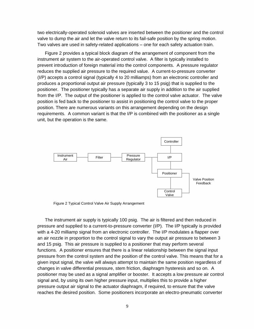
Figure 2 provides a typical block diagram of the arrangement of component from the
instrument air system to the air-operated control valve. A filter is typically installed to
prevent introduction of foreign material into the control components. A pressure regulator
reduces the supplied air pressure to the required value. A current-to-pressure converter
(I/P) accepts a control signal (typically 4 to 20 milliamps) from an electronic controller and
produces a proportional output air pressure (typically 3 to 15 psig) that is supplied to the
positioner. The positioner typically has a separate air supply in addition to the air supplied
from the I/P. The output of the positioner is applied to the control valve actuator. The valve
position is fed back to the positioner to assist in positioning the control valve to the proper
position. There are numerous variants on this arrangement depending on the design
requirements. A common variant is that the I/P is combined with the positioner as a single
unit, but the operation is the same.
Controller
Instrument Air
Filter
Pressure Regulator
I/P
Positioner
Valve Position
Feedback
Control Valve
The instrument air supply is typically 100 psig. The air is filtered and then reduced in
pressure and supplied to a current-to-pressure converter (I/P). The I/P typically is provided
with a 4-20 milliamp signal from an electronic controller. The I/P modulates a flapper over
an air nozzle in proportion to the control signal to vary the output air pressure to between 3
and 15 psig. This air pressure is supplied to a positioner that may perform several
functions. A positioner ensures that there is a linear relationship between the signal input
pressure from the control system and the position of the control valve. This means that for a
given input signal, the valve will always attempt to maintain the same position regardless of
changes in valve differential pressure, stem friction, diaphragm hysteresis and so on. A
positioner may be used as a signal amplifier or booster. It accepts a low pressure air control
signal and, by using its own higher pressure input, multiplies this to provide a higher
pressure output air signal to the actuator diaphragm, if required, to ensure that the valve
reaches the desired position. Some positioners incorporate an electro-pneumatic converter
Figure 2 Typical Control Valve Air Supply Arrangement
10
so that an electrical input (typically 4 - 20 mA) can be used to control a pneumatic valve
eliminating the need for a separate I/P. Positioners have a feedback loop of valve position
back to the positioner.
3.1.2 Instrument Air Systems
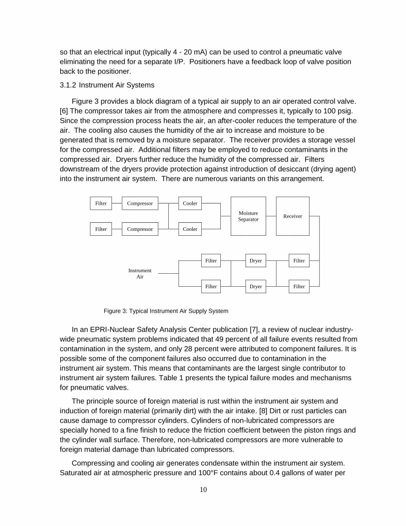
Figure 3 provides a block diagram of a typical air supply to an air operated control valve.
[6] The compressor takes air from the atmosphere and compresses it, typically to 100 psig.
Since the compression process heats the air, an after-cooler reduces the temperature of the
air. The cooling also causes the humidity of the air to increase and moisture to be
generated that is removed by a moisture separator. The receiver provides a storage vessel
for the compressed air. Additional filters may be employed to reduce contaminants in the
compressed air. Dryers further reduce the humidity of the compressed air. Filters
downstream of the dryers provide protection against introduction of desiccant (drying agent)
into the instrument air system. There are numerous variants on this arrangement.
Filter
Compressor
Cooler
Moisture
Separator
Receiver
Filter
Compressor
Cooler
Filter
Dryer
Filter
Instrument
Air
Filter
Dryer
Filter
In an EPRI-Nuclear Safety Analysis Center publication [7], a review of nuclear industry-
wide pneumatic system problems indicated that 49 percent of all failure events resulted from
contamination in the system, and only 28 percent were attributed to component failures. It is
possible some of the component failures also occurred due to contamination in the
instrument air system. This means that contaminants are the largest single contributor to
instrument air system failures. Table 1 presents the typical failure modes and mechanisms
for pneumatic valves.
The principle source of foreign material is rust within the instrument air system and
induction of foreign material (primarily dirt) with the air intake. [8] Dirt or rust particles can
cause damage to compressor cylinders. Cylinders of non-lubricated compressors are
specially honed to a fine finish to reduce the friction coefficient between the piston rings and
the cylinder wall surface. Therefore, non-lubricated compressors are more vulnerable to
foreign material damage than lubricated compressors.
Compressing and cooling air generates condensate within the instrument air system.
Saturated air at atmospheric pressure and 100°F contains about 0.4 gallons of water per
Figure 3: Typical Instrument Air Supply System

11
1000 cubic feet of air. If this air is compressed to 100 psig and cooled to 80°F, the water
content in the air will only be about 0.025 gallons per 1000 cubic feet of air. This is
equivalent to a removal of 22 gallons per hour for a 1000 CFM capacity compressor. If this
water is not consistently removed it can initiate corrosion within the system. Solenoid
valves, pneumatically operated valves, pilot valves, and I/P converters are especially
vulnerable to failure due to foreign particle incursions.
Table 1: Pneumatic Control Valve Failure Modes
Component type
Function Failure Modes
Failure Mechanism
Effect on System
Comments
Filter Regulator
Supply filtered compressed air
High pressure Low pressure Erratic pressure regulation
Air leaks Diaphragm failure Spring failure Foreign material contamination
Consequential failure of downstream components.
Typically between 20 and 50 psig
Electro pneumatic transducer
Convert an electronic control signal to a proportional air pressure.
High pressure Low pressure Erratic pressure regulation
Air leaks Diaphragm failure Spring failure Foreign material contamination Force motor failure
Failure of valve to position correctly
Typically the control signal is 4-20 milliamps corresponding to 3-15 psig
Positioner Provide air pressure to valve actuator to accurately position valve
High pressure Low pressure Erratic pressure regulation
Air leaks Diaphragm failure Spring failure Foreign material contamination
Failure of valve to position correctly
Positioner may incorporate the functions of an electro pneumatic transducer
Actuator Position valve
Valve go to failure position Valve go to position opposite failure position Erratic valve operation
Air leaks Diaphragm failure Spring failure Stem binding
Failure of valve to position correctly
In nuclear facilities, if an air operated valve is used in a nuclear safety-related
application, an accumulator is typically used to back-up the non-safety related air supply.
The accumulator is normally equipped with check valves to assure an air supply is available
for the AOV if the normal air supply fails. Foreign material within the system may become
lodged on the check valve seat potentially allowing excessive leakage from the accumulator.

12
If the service air system is used as a backup to instrument air system gross moisture
contamination of the instrument air system can occur unless the cross connection is made
prior to dryer pre-filters.
I/P converters are susceptible to air-line contamination, particularly dirt and rust. Due to
extremely small ports inside the I/P converter any dirt or rust that enters the device can start
plugging ports and causing sluggish response. Filters are installed in the air line just
upstream of the I/P converter to mitigate the problem. Plugging of the filter can lead to
degradation of the valve performance.
Pneumatic valve operators may have diaphragms made of a neoprene or rubber
compound that deteriorates in the presence of hydrocarbon contamination. They may also
be exposed to dirt and rust inside the actuator causing the valve to stick.
3.1.3 Digital Pneumatic Control
A positioner is a device that accepts a control signal and varies the air pressure applied
to the valve actuator until the control valve achieves the position demanded by the control
signal. A positioner is used for the following reasons.
• Minimize the hysteresis of the control valve due to packing friction
• Offset variations in valve actuator spring rate
• Improve the valve response time
• Compensate for variations in the internal valve pressure applied to the stem
Figure 4 provides a block diagram of an example digital valve positioner. On the front
end, a microprocessor accepts the control signal and adjusts the signal to the I/P based on
the output pressure, the supply pressure and the valve position. The I/P provides a
pressure signal to a pneumatic relay that amplifies the signal and provides the pressure to
the valve actuator.
Digital positioners offer a number of advantages in four fundamental areas.
• High reliability
• Improved operational performance
• Increased productivity and reduce maintenance costs
• On-board diagnostics for early warning of pending failure modes
It should be noted that the use of a digital positioner does not negate the susceptibility to
the instrument air quality issues that are described above, although the on-board
diagnostics can detect some of the instrument air failure modes.
Since the early 1990’s, over a million digital valve positioners have been sold worldwide
adding up to billions of operational hours. [9] The modular design of some of the models
isolates the field terminal compartment from internal positioner components. Many are
designed to function in adverse environmental conditions such as elevated temperatures
and high vibration service.

13
Pressure Sensor
Air Supply
Pressure Sensor
Control Signal
Microprocessor
I/P
Pneumatic Relay
Control Valve
Valve Position
Operational performance is enhanced through improved accuracy of the digital
positioner. The improved accuracy is achieved by enabling consideration of a number of
factors digitally to adjust the positioner output pressure. Self-tuning features improve the
dynamic response of the associated control valve resulting in better process control. The
digital nature of the positioners permit remote diagnostics to be performed routinely or
whenever deemed appropriate. These diagnostics have the capability to detect a variety of
issues related to the control valve functionality such as the following potential problems.
• air leakage
• valve assembly friction and dead band
• instrument air quality
• loose connections
• supply pressure restriction
• valve assembly calibration.
The availability of diagnostics permits early identification of degradation allowing
corrective action to be taken and avoiding an upset condition. The diagnostic capability also
facilitates characterization of the valve performance following maintenance on the valve to
increase the assurance that the valve will function properly when returned to service.
Implementing digital positioners on critical control valves also enables online partial
stroke testing of the control valve without upsetting the normal process control. This testing
provides assurance that the control valve will actually move on demand.
Increased productivity and reduced maintenance costs are possible through the
following factors.
• remote configuration, calibration and diagnostics
• non-contact feedback technology
• valve position information availability
• remote mounting of positioner
• online valve testing
Figure 4 Example Digital Valve Positioner Block Diagram

14
• modular design
• inventory reduction
The ability to remotely configure, calibrate, and diagnose the health of the controls may
simplify maintenance. Digital positioners have the ability to self-calibrate, potentially
eliminating the need to access the valve locally. If the valve is located in a radiological
controlled area, personnel radiation exposure may be reduced. Depending on the specific
valve location, implementing personnel safety measures such as scaffolding may be
avoided if the maintenance can be conducted remotely. If maintenance on a digital valve
positioner is required, the modular design of the positioner simplifies the repair.
Some digital valve positioners can be coupled with non-contact valve position sensing to
eliminate common problems associated with valve position linkage assemblies. Several
designs utilize a magnet assembly to regulate the output of a Hall effect sensor that is
proportional to the valve position. Since the magnet is in proximity to the Hall effect sensor
but does not contact it, the mechanical linkage is eliminated. This also permits locating the
positioner away from the valve if vibration is a problem. With digital valve position indication,
the position information may be transmitted to the control room if this information is useful to
operations personnel.
A single digital valve positioner model can be used in multiple applications and on most
valve assemblies. Using a common positioner may allow a reduction in the spare parts
inventory reducing the spare parts inventory expense. The optional integral valve position
transmitter eliminates the need for a separate valve position transmitter.
3.1.4 Industry Experience
At a Midwestern nuclear unit, digital positioners had been installed on the main
feedwater control valves. [10] Several years after the installation, steam leaks developed on
two of the valves gradually increasing the instability of the valves. It was decided to
implement a common temporary valve packing repair while maintaining the valves in service
and the plant online. The digital valve positioners were vital during this process because of
the information on the condition of the associated valve during and following the temporary
packing repair.
Likewise, a Southern nuclear unit installed digital positioners on the main feedwater and
feedwater bypass valves on both units. [11] They installed redundant positioners on the
main feedwater valves to assure reliability, and used remote mount models so that the
electronic portion of the positioner could be panel mounted with only the feedback device
mounted on the valve. They used single positioners on the main feedwater bypass valves.
Installation of the digital positioners permitted tuning the control of the steam generator
levels to a more stable control. Subsequently, digital positioners were also installed on their
main steam to condenser dump valves. These valves must stroke very quickly during a
turbine load rejection while exhibiting stable pressure control during start up and shut down
operations. Since the digital positioners have higher air volume capability than the previous
analog positioners, the utility was able to remove the volume boosters and simplify the
15
control scheme used on these valves. This has given the utility the ability to monitor and
troubleshoot the valves from a controlled environment while minimizing time out in the field.
At an Eastern nuclear unit, digital positioners have been implemented in a number of
applications. [11] Several years ago, the unit experienced a reactor trip where the root
cause was determined to be inadequate design of the air supply to the main feedwater
bypass valve controls. One of the modifications that were implemented was the installation
of digital valve positioners on these valves. As a result of installing the digital valve
positioners, the higher flow rates of the new positioners allowed elimination of the volume
boosters. The digital positioners are capable of on-line performance diagnostics so that
they can monitor performance of the positioner, the valve, and the process. With fewer
components to maintain, this predictive approach to maintenance should reduce work load
in the future.
At another Eastern nuclear unit, digital positioners were installed on the main feedwater
regulating valves. [12] Some initial problems with valve control were investigated using on
line diagnostics. It was determined that the valve position linkage was the source of the
problem and the valve position was upgraded to a non-contact system. Based on the
positive experience of using digital positioners on the main feedwater regulating valves,
digital positioners were included in an upgrade of the moisture separator and heater drain
controls. These systems have stabilized and the cycling has essentially been eliminated.
The moisture separators and heater drains are now working as designed and have
improved overall plant efficiency. With stable operation the valves are lasting much longer
without having to be maintained. The preventive maintenance (PM’s) intervals have been
extended from the 18 months to 6-8 years.
At another Southern nuclear unit, redundant digital valve positioners have been installed
on the main and bypass feedwater regulating valves, main feedwater pump temperature
control and the main steam bypass valves. [12] Due to the local ambient temperature at the
main feedwater regulating valves, the positioners were mounted remotely and non-contact
valve position monitoring was installed.
All of these modifications are examples of installation of digital valve positioners on
critical control valves. The above discussion also applies to air operated ventilation dampers
where proportional control is employed.
3.2 Hydraulic Actuators
3.2.1 Analog Hydraulic Actuators
Hydraulic actuators are similar to pneumatic actuators and are used where more force
is needed. Electro-hydraulic actuators have an electric motor-pump set to create the
hydraulic pressure, which is then applied to a piston in a cylinder to deliver the actuating
force. Often this force is applied against a spring so that any intermediate position of the
valve or damper can be obtained by providing the amount of hydraulic force needed to
compress the spring to the desired point. The spring also serves to provide a fail-safe

16
mechanism in which the spring returns the valve to a desired position (either open or
closed) on loss of hydraulic pressure.
Typical examples of hydraulic valve actuators are the governor and throttle valves on
the high-pressure section of a large turbine. These valves are used to control the amount
of steam flow into the turbine. The hydraulic valve actuators are able to provide precise
valve position control in order to make fine adjustments to turbine speed or to megawatt
output when the turbine is driving a generator in synchronous conditions. The large
springs are able to close the governor and turbine valves very rapidly for emergency
conditions (such as following a reactor trip) by venting the hydraulic oil to relax the
pressure.
3.2.2 Hydraulic Oil Supply System
The design of hydraulic control systems varies widely. Typical common components
include the following.
• Reservoir
• Hydraulic pumps
• Actuators
• Filters
• Coolers
• Accumulators
• Trip valve
Most hydraulic control systems incorporate two independent motor driven pumps, each
capable of supplying 100% system capacity. Normally, one pump is in operation with the
other in standby. The standby pump starts if there is low pressure in the common discharge
header. The actuators modulate the hydraulic pressure to the control valve to position the
valve based on the electronic control signal. The trip valves bypass the actuators causing
the supplied hydraulic pressure to be relieved allowing the control valve to go to the trip
position. EPRI conducted an investigation into the performance of main turbine electro
performance at nuclear plants. [13] An analysis of the approximately 50 EHC system-
related reactor trips provided the following breakdown by components:
EHC Pumps 8
Trip Devices 10
Piping/Tubing/Fittings 11
Actuator Components 18
As indicated above, actuator components were most often involved in hydraulic control
related reactor trips. A breakdown of the actuator components involved in the reactor trips is
as follows:
• Six servo valves
• Two limit switches
• Two solenoid valves
• Two linear voltage differential transformers (LVDTs)

17
• Six other components
A significant number of piping/tubing, and fitting leaks resulted in reactor trips. Most of
the leaks were at the actuators, and in many cases the root cause was attributed to
vibration. A review of the various root causes reveals several common factors in many of the
reactor trips related to EHC system problems (several events had multiple causes).
• Fluid Contamination 3
• Maintenance/Operations Errors 7
• Testing Involved 11
• Electrical Failure 12
• Vibration Induced 12
O-rings must be of the proper size and made of a material compatible with phosphate
ester fluid. Vibration is a significant factor in many leaks. Vibration at the EHC pump skids
and steam valve actuators stresses tubing and connections, often leading to failure.
Vibration at the actuators is also a significant cause of limit switch adjustment problems.
Steam generator feed pumps typically use hydraulic controls somewhat similar to main
turbine control systems. A significant difference is that the oil is common with the lubricating
oil system. As with pneumatic systems, foreign material contamination of the oil is a primary
problem. Wear at pivot points leads to poor speed control.
Oil fire is a significant hazard. To mitigate this risk, a fire detection and mitigation
system, such as a deluge system, is typically installed to cover the area exposed to the fire
hazard. This is usually a large area in that the oil is pressurized and the spray zone is large.
The fire detection and mitigation system must be continually tested and repaired, further
adding to the cost of using a hydraulic actuator system.
3.2.3 Digital Replacements for Hydraulic Actuators
A viable replacement for analog hydraulic actuators is a digitally-controlled electro-servo
actuator, also known as a electro-mechanical linear actuator. An electro-servo actuator is a
high-speed electric motor that typically uses a roller screw to achieve fast, accurate linear
motion. Due to a number of design features, they are faster than conventional electric
actuators that rely on reduction gears to translate motor speed to valve movement. They
are more accurate than hydraulic actuators, being able to resolve position within a fraction of
a turn of the roller screw using advanced positioning feedback. In addition, the accuracy
and repeatability are exceptionally good due to very low hysteresis in the roller screw drive
system.
With a digital interface, the electro-servo actuator is able to directly translate a position
demand for the plant control system into an actuation signal with no degradation due to loop
drift or other types of signal fidelity loss. It is able to self-calibrate by articulating the entire
range of motion when first initialized. By contrast, the calibration of a hydraulic actuator is
far more complex and time consuming.
Digital communication capability contributes to the overall accuracy of the application
when connected to a digital control system, as is becoming more common as nuclear plants

18
install distributed control systems. In these situations, the demand (position) signal is
communicated in digital form all the way to the electro servo actuator with no signal
degradation. This is not true in an analog communication scheme such as a 4 – 20 mA
current loop. Even though a feedback circuit is used to adjust the signal to the desired
process state, there is hysteresis in these components that limits the precision of the
positioning. This builds up error in the feedback control circuit and often results in
continuous actuator motion or “hunting.”
In addition to the operational benefits, there is considerably less maintenance with an
electro-servo actuator. Foremost is the amount of maintenance on the oil system itself,
which requires filter changes, periodic oil cleaning or replacement, and repair of leaks
around fittings and moving parts. There is also significant maintenance required to keep the
hydraulic system in good working order, including the hydraulic oil pump, oil cylinder or
piston, porting valves, and over-pressure protection devices.
There are a number of operational benefits with electro servo actuators:
• The elimination of hydraulic actuators also removes a significant fire hazard. The
high-pressure oil is also a personnel safety concern, requiring protective clothing and
special precaution when working around these energized systems.
• They are much easier to install, requiring only the connection of electrical cables
rather than hydraulic fluid fittings.
• The footprint of the installation is much smaller. Typically, the entire electro servo
actuator fits into the same space as the hydraulic cylinder and does not require the
additional space needed for a hydraulic pump, filter, and oil reservoir tank.
• The electro servo actuator is more energy efficient, drawing power only when it is
repositioning as opposed to a hydraulic pump, which runs continuously.
• The operation of an electro servo actuator is much quieter than the hydraulic system.
It should be pointed out that electro-servo actuators can also be used as replacements
for pneumatic actuators – both for modulating (control) valves as well as open-close
applications. In this regards, they can be used to eliminate the need for instrument air
usage as described in Section 3.1.
A leading supplier of electro servo actuators for the nuclear power industry is the Exlar
Corporation. These actuators incorporate a high performance brushless servo motor with a
novel mechanism for converting the motor’s rotary power and speed to a highly accurate
and reliable linear or rotary motion. A high
performance closed loop controller yields both the
speed and precise control unachievable by other
electric actuators. These electric servo actuators
were designed for use on full modulating valves and
dampers.
The Exlar design uses a motor wrapped around
an inverted roller screw (Figure 5), which is a
mechanism for converting rotary torque directly into
Figure 5. Exlar Roller Screw
mechanism for linear motion.

19
linear motion. Multiple threaded helical rollers are assembled in a planetary arrangement
which converts a motor's rotary motion into linear movement of the shaft. [14]
• Drive motor turns up to 5000 RPM, translating to linear movement up to 40 inches
per second. This provides extremely fast response time to complete the desired
travel, with little or no overshoot or oscillation. [15]
• Depending on the selected application, one motor revolution is divided into as many
as 3,200,000 incremental positions. The fine resolution of the feedback device
results in a continuous position accuracy of roughly 0.001” when used with a 0.1”
lead roller screw in a linear application. [14]
• Duty cycle is 100% continuous. [16]
• Design life of hundreds of millions of strokes vs. thousands for most types of electric
actuators. [16]
Exlar actuators provides closed loops feedback, eliminating the need for limit switches,
torque switches or any mechanical means of feedback found in typical actuators, further
extending the life. In addition, the feedback mechanism is integral with the motor shaft and
therefore has very little hysteresis. [14]
It accepts a variety of digital communication types, including Ethernet IP, Modbus TCP,
and Profinet. It also accepts 4-20 mA input for analog applications. Using a second
transmitter, it has the ability to provide precise position information back to the control
system or the operator.
Also, there are no limit switches involved as in the case of conventional motor actuators.
These require significant maintenance to set up and maintain. [17] Finally, there are
diagnostic capabilities with these actuators that reduce troubleshooting and maintenance
effort.
Energy consumption is significantly lower for electro-servo actuators as compared to
hydraulic actuators. In one particular side-by-side test by the University of Kassel in
Germany, hydraulic actuators were compared with electro-servo actuators in a test rig to
move a 100 kg load on an identical workload and duty cycle basis. [18] Over a projected
operating time of 6000 hours per year, the energy consumed by the hydraulic operator
system (primarily due to the continuously-operating hydraulic pump) would be 3602 kwh
whereas the energy consumed for an equivalent electro-servo actuator would 816 kwh. In
other words, the electro-servo actuator would consume less than 23% of the energy
required by the hydraulic operator. Extrapolated to larger loads and more applications, the
energy savings become very compelling for reducing plant operational costs.
3.2.4 Industry Experience
There has been limited application of electro servo actuators in the nuclear industry for a
variety of reasons. One notable implementation of Exlar electro servo actuators was the
feed regulation valves for the turbine driven feedwater pumps at McGuire Nuclear Station.
This actuator replaced a hydraulic cylinder that was previously used to modulate a rack and

20
cam arrangement that in turn was used to lift a series of poppet valves to control steam flow.
This has resulted in considerable setup and maintenance savings for these valves. It has
also greatly improved the performance of the feedwater pumps in terms of flow control. [16]
Exlar actuators have also been installed on the main feedwater pump turbines at Calvert
Cliffs, Arkansas Nuclear One, and Columbia Generating Station.
Other installations include a feedwater pump retrofit at a Western nuclear utility and the
application of Exlar actuators for a Terry Turbine application, which is a single stage steam
turbine for emergency feedwater pumps. Many are installed U.S. Navy nuclear ships as
well.
As the nuclear industry continues to face cost pressure in the electric market it place, the
use of electro servo actuators is one example of where ongoing maintenance costs can be
significantly offset by pursuing these component upgrades.
3.3 Motor Control Centers
3.3.1 Motor Control Center Description
A motor control center (MCC) is an assembly of one or more enclosed vertical metal
cabinet sections having a common power bus and principally containing motor control
units. Motor control centers are usually used for low voltage three-phase alternating
current motors from 208 V to 600 V.
Each vertical metal cabinet section (bucket) has a power bus and provision for plug-in
mounting of individual motor controllers. Each motor controller contains a contactor or a
solid-state motor controller, overload relays to protect the motor, fuses or a circuit breaker
to provide short-circuit protection, and a disconnecting switch to isolate the motor circuit.
Three-phase power enters each controller through separable connectors. The motor is
wired to terminals in the controller. Motor control centers provide wire ways for field
control and power cables.
Each motor controller in an MCC can be specified with a range of options such as
separate control transformers, pilot lamps, control switches, extra control terminal blocks,
various types of thermal or solid-state overload protection relays, or various classes of
power fuses or types of circuit breakers. A motor control center can either be supplied
ready to connect all field wiring, or can be an engineered assembly with internal control
and interlocking wiring to a central control terminal panel board or programmable
controller.
The performance characteristics of motor control centers are a function of the
installed components, the age of the equipment and the environment surrounding the
MCC.
Age, adverse environment, and/or vibration can lead to degraded connections within
the motor control center. Degraded connections lead to overheating that creates a higher

21
potential for fires. Periodic inspection particularly when coupled with thermography can
detect degraded connections and enable mitigation of the consequences.
There are several different types of circuit breakers such as magnetic, thermal
magnetic and molded case. Magnetic and thermal magnetic are very similar with the
primary difference is the addition of a thermal trip function to a magnetic circuit breaker.
These breakers are typically capable of remote operation. Molded case circuit breakers
are typically used for small loads. If remote or automatic operation is required, a contactor
is installed. Age and adverse environmental conditions can cause degradation of circuit
breakers and other MCC components. The typical symptom of a degraded circuit breaker
is erratic operation possibly resulting in degradation to the electrical protection scheme or
failure to close on demand.
Thermal overloads in the MCC provide protection for mechanical overload of the
motor and upset electrical supply conditions such as low supply voltage. There are
several different types of thermal overload. Their principal function is to detect a high
current and interrupt power to the motor before damage occurs. Typically other means of
electrical protection are provided for electrical fault conditions. Again, age and adverse
environmental conditions can degrade reliable operation of thermal overloads. High
ambient environmental temperature can lead to premature tripping of a thermal overload.
Many MCC buckets are equipped with control transformers to provide reduced voltage
for the control circuit. Since the transformers are continuously energized. The insulation
may degrade over time and cause the transformer to fail possibly resulting in a failure of
the load to operate and a possible electrical fire.
MCC buckets are frequently equipped with fuses and fuse holders. Imperfections in
the fuse element can cause the fuse to fail over time. Periodic removal and replacement
of the fuses can deteriorate the fuse holder, resulting in a degraded connection, increased
resistance, fuse heating and premature failure of the fuse.
Relays and contactors are very similar with contactors typically having higher current
ratings. Age and foreign material contamination from the environment can cause mis-
operation of these devices.
Motor control centers can be upgraded with industry leading components, without
replacing the structure and bus. Motor control center structures and internal bus work
typically have a long life. Their unit racking systems are simple and most likely, in good
shape. New direct replacement motor control center units are available for many common
vintage and current style MCCs. This approach minimizes outage time and reduces costs
associated with having to match existing footprints for the removal and reinstallation of
cables. Buckets can be replaced one at a time over an extended period, which provides
an overall equipment upgrade on a limited maintenance budget.

22
3.3.2 Digital Technology for Motor Control Centers
Motor control centers that utilize various digital devices are available from a number of
suppliers. Digital motor control centers typically incorporate a digital communication
interface and have a number of options available that can improve performance. The
current and voltage is continuously digitized and capable of transmission. The benefits are
increased reliability, reduced maintenance, remote diagnostics, sequence of events
recording, improved electrical protection of the loads, and reduced personnel hazard.
Increased reliability can result from several different available features of digital motor
control centers, primarily from the ability to easily perform diagnostics. Since the current
and voltage can be monitored for each load trending of these parameters for each load is
facilitated. Changes in these parameters may be indicative of a serious problem that can be
corrected prior to failure. Motor current signature analysis may also be possible that can
broaden the spectrum of problems that may be detected in advance of a failure.
A second feature of digital motor control centers is the ability to perform soft starts of the
connected motors. Soft starts reduce the motor inrush current by ramping up the applied
voltage on a start avoiding the more severe application of full voltage with the motor at rest.
A third available feature is that solid state overload relays may be used to replace
conventional thermal overloads. These relays provide a more accurate assessment of the
thermal condition of the motor potentially avoiding unnecessary thermal trips. Additional
protection of the load is available through detection of a phase loss, current imbalance, a
ground, a stall of the associated motor, or a significant underload condition. Remote
operation of the thermal overload relay is an available feature as well as automatic reset of
the relay following a thermal overload trip.
Arc flash detection and protection is available with digital motor control centers. Flash
detection within the MCC is coupled with incoming current monitoring to determine if a trip of
the incoming circuit breaker is appropriate. This may serve to significantly limit the energy of
the arc flash assisting in protection of personnel.
3.3.3 Industry Experience
A survey of information on digital motor control centers in nuclear power plants resulted
in some identification of experience with them. The Aging Management Guideline for
Commercial Nuclear Power Plants - Motor Control Centers [19] discusses a number of
issues relative to motor control centers that have been identified to be addressed if license
extension is to be considered.
One utility had issues with commercial grade dedication of new digital breakers with
complex software algorithms installed. Their choice was to replace with digital breakers with
much more simple software that could be 100% tested. The choice of digital breakers with
more complexity also brings into play additional issues, such as cyber security.

23
Several electrical fires have occurred in MCCs caused by high resistance connection
within the bus work connections. These fires typically cause extensive damage to the MCC.
Digital MCCs may assist in mitigating problems with bus work connections through internal
temperature monitoring.
Molded case circuit breakers (MCCBs) have not functioned properly attributed to high
internal temperature. Digital MCCs may assist in mitigating problems with MCCBs by
facilitating temperature monitoring within the MCC.
Contactors and relays have failed numerous times, many attributed to prolonged periods
of being energized and/or aging. Certain time delay relays have experienced erratic
performance. Digital MCCs may substantially reduce problems with control relays by
eliminating them from the MCC. Digital MCCs may assist in mitigating problems with
contactors by facilitating temperature monitoring within the MCC.
Although there were no issues with control transformers in the Aging Management
Guideline [19], it may be possible to eliminate many of them and reducing the heat load
within the MCC and mitigating failures of other components within the MCC.
For utilities planning license extension, replacement of buckets with digital MCC
components may be cost effective.
3.4 Variable Frequency Motor Drives
3.4.1 Variable Frequency Drive Description
This section provides an overview and benefits of the use of variable frequency drives
(VFD), also known as variable speed drives (VSD), for controlling large pumps in nuclear
power plants. Section 3.4.3 provides industry experience on how variable speed drives
with digital controls have been incorporated in Boiling Water Reactors (BWR) and
Pressurized Water Reactors (PWR) with significant reliability and cost saving results.
Variable frequency drives (VFD) are equipment used to control the speed of
machinery, ranging from small appliances to the largest of mine mill drives and
compressors. Many industrial processes such as assembly lines must operate at different
speeds for different products. When process conditions demand adjustment of flow from a
pump or fan, varying the speed of the drive may save energy compared with other
techniques for flow control. In this type of control the output speed can be changed
without steps over a range. VFD’s may be purely mechanical (termed variators),
electromechanical, hydraulic, or electronic. The focus of this section will be on the use of
VFD’s to enhance plant performance and also the benefits of digitally controlled VFD’s
versus the earlier analog versions.
Process control and energy conservation are the two primary reasons for using a
variable speed drive. Historically, VFD’s were developed for process control, but energy
conservation has emerged as an equally important objective.

24
A VFD is a type of adjustable-speed drive used in electro-mechanical drive systems to
control AC motor speed and torque by varying motor input frequency and voltage.
For an example, applicable to nuclear plants, a variable speed drive is use to control
the recirculation pumps which change the water flow thru the reactor core.
Changing (increasing or decreasing) the flow of water through the core is the normal
and convenient method for controlling power from approximately 30% to 100% reactor
power. When operating on the so-called "100% rod line," power may be varied from
approximately 30% to 100% of rated power by changing the reactor recirculation system
flow by varying the speed of the recirculation pumps or modulating flow control valves. As
flow of water through the core is increased, steam bubbles ("voids") are more quickly
removed from the core, the amount of liquid water in the core increases, neutron
moderation increases, more neutrons are slowed down to be absorbed by the fuel, and
reactor power increases. As flow of water through the core is decreased, steam voids
remain longer in the core, the amount of liquid water in the core decreases, neutron
moderation decreases, fewer neutrons are slowed down to be absorbed by the fuel, and
reactor power decreases.
A typical VFD is shown in Figure 6. A VFD is an electrical system (i.e. inverter) used to
control AC motor speed and torque. It provides a continuous range of process speeds
compared to a discrete control device such as multiple-speed motors or gearboxes. A
VFD controls motor speed by varying the frequency supplied to the motor. The drive also
regulates the output voltage in proportion to the output frequency to provide a relatively
constant ratio of voltage to frequency (V/Hz), as required by the characteristics of the AC
motor to produce torque.
Many motors in nuclear plants run at outputs that are higher than required by the plant
process:
For example:
• Recirculation pumps and other large pumps have control valves to reduce flow,
resulting in a significant loss of energy
DC-AC Inversion
AC Output; Variable Frequency, Variable Voltage
Trans- former Motor
AC-DC Conversion
AC Input; Fixed Frequency, Fixed Voltage
Figure 6 Variable Frequency Drive

25
• Cooling water pumps that always run at the same speed, independent from the
temperature of the water
• Large air handler fans that have no speed control despite the changing air
temperature.
3.4.2 Digital Technology for Variable Frequency Drives
The advantages of VFD’s in the nuclear industry are many as discussed in a paper
published in IEEE PEDS 2011 [20]. Nuclear plants, especially BWR’s are including VFD’s in
their AC power systems in many cases now to improve the reliability, efficiency and
enhanced compliance with the Clean Water Act.
The benefits of VFD’s can be categorized in the following:
• Higher efficiency and improved power consumption.
VFD’s allow the plant operators to operate motors and pumps at the precise speed
needed for the process. With the ability to vary motor and pump speed, system
efficiency is increased. The enhanced control allows the operators to only consume
the energy required for system needs. Compared to fixed-speed pumps with flow
controlled via valves, VFD’s can provide large savings in power consumption.
Improved motor efficiency up to 96.5% from around 82% in direct power connections.
This can mean 3-4 MW savings across large motors.
• Higher reliability and availability
VFD’s have proven to be more reliable than motor-generator (M-G) sets. One nuclear
plant reported a four-fold increase in system reliability after the installation of VFD’s on
their reactor recirculation pump motors.
Also, there is a major benefit in the implementation of redundancy in the design – both
redundancy in the logic and redundancy in the sensor strings, which supports single
point of failure analyses. New digital VFD’s have redundant power cells – which can
lose 2 and still maintain 100% power. If a power cell fails, it swaps over to a good one
in 8 cycles with minor loss of RPM.
• Reduced maintenance
VFD’s have been shown to reduce maintenance on the motors by reducing parts
requirements, eliminating mechanical linkages, scoop tube adjustments and oil
handling concerns associated with M-G sets.
• Improved flow control in condenser applications
This has the benefit for the 316B, Clean Water Act rule that plants can reduce flow
rate of condenser cooling and not have as much fish impingement. Without VFD’s, the
pumps are in a fixed control mode, which does not allow for efficiency variation based
on inlet temperature changes. Environmental Protection Agency studies have shown
that a reduction in fish intrusion is directly proportional to the reduction in flow rate at
the intake structure.

26
• Soft start
The VFD can be used to ‘soft start” a motor. The controlled startup minimizes current
in rush to motor windings which can extend motor life.
• Elimination of portions of the fire detection and suppression system
As a result of removing M-G sets, this also eliminates the fire detection and
suppression system requirements associated with the oil for the clutch with the M-G
sets.
• Improvements in fill and vent activities.
Rather than “bumping” RCP motors to sweep out voids, the operators can leave a
pump in idle (very low RPM) rather than turning it off. This way, the operators can
reduce the number of starts on these very larger RCP motors and extend the life of
the motors.
• Reduced water hammer
These dangerous conditions can be reduced due to slower pump motor starts with the
VFD.
3.4.3 Industry Experience
Applications of VFD’s (Figure 7) have been made at multiple plants in a number of
systems as follows:
• Reactor Recirculation System (RRS). Replacement of the M-G sets with VFD’s
provide a much higher degree of flow control for meeting reactor safety margins while
optimizing the performance of the plant. Also, the VFD’s provide the benefits
described above in power savings
(Example: 4MW/plant) and extended
life for the motors.
• Circulating Water (CW) pumps, to
provide more flexibility in flow control
based on ultimate heat sink inlet
temperature changes and other
requirements. This allows reduction in
fish kill, enhanced compliance with the
Clean Water Act, power savings and
extended motor life.
• Refueling Machines. VFD’s have
been installed in place of fixed speed
motors in refueling machines to
provide more precise location and moving of fuel rods and extended motor life.
Instead of “bumping” a motor to make sure the location is correct, the VSD allows the
motor location to be brought to an exact spot. This is critical because the work of the
Figure 7. VFDs In Operation at Millstone

27
refueling machine is almost always on a critical path schedule and any time delays,
will be very hard to make up. One plant lost a significant amount of time on the
beginning of an outage because the refueling machine motors burned up and required
replacement on critical path.
This case study will address the application of variable speed drives (VFD) to Boiling
Water Reactors (BWR) and Pressurized Water Reactors (PWR) for improvement in
reliability, energy efficiency and enhanced compliance with the Clean Water Act.
A VFD is a type of adjustable-speed drive used in electro-mechanical drive systems to
control AC motor speed and torque by varying motor input frequency and voltage.
For an example, applicable to nuclear plants, a variable speed drive is use to control the
recirculation pumps which change the water flow thru the reactor core, and also reactor
power (Figure 8).
Changing (increasing or decreasing) the flow of water through the core is the normal and
convenient method for controlling power. As flow of water through the core is decreased,
steam voids remain longer in the core, the amount of liquid water in the core decreases,
neutron moderation decreases, fewer neutrons are slowed down to be absorbed by the fuel,
and reactor power decreases.
The benefits from changing from M-G sets to VFD’s have been shown in the large
number of conversions that have occurred since 1995. Twenty-six reactor recirculation
pump VFD’s are in operation in BWR’s in the U.S. as shown in Table 1 and six VFD’s are
scheduled for installation in reactor recirculation pumps. Also, 10 Condenser Circulation
Water (CCW) VFD’s are currently in operation. The benefits from installation of the VFD’s
are shown in Section 3.4.2 above, resulting in large savings in the annual budget for
Figure 8. BWR Depicting Recirculation Pump
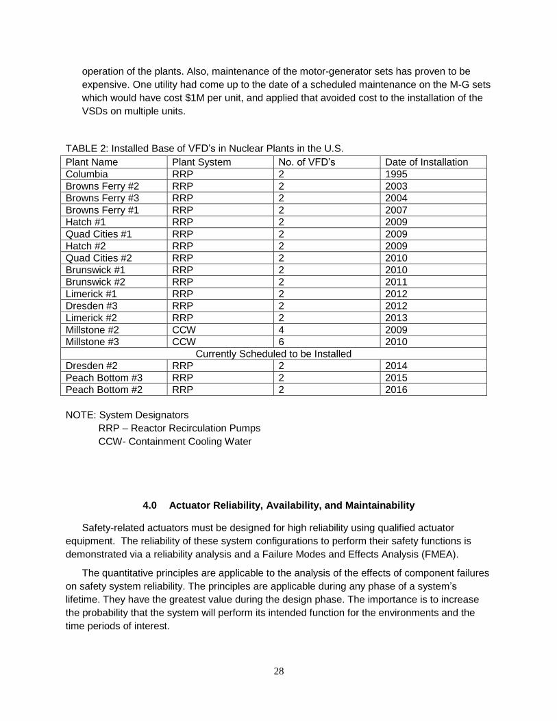
28
operation of the plants. Also, maintenance of the motor-generator sets has proven to be
expensive. One utility had come up to the date of a scheduled maintenance on the M-G sets
which would have cost $1M per unit, and applied that avoided cost to the installation of the
VSDs on multiple units.
TABLE 2: Installed Base of VFD’s in Nuclear Plants in the U.S.
Plant Name Plant System No. of VFD’s Date of Installation
Columbia RRP 2 1995
Browns Ferry #2 RRP 2 2003
Browns Ferry #3 RRP 2 2004
Browns Ferry #1 RRP 2 2007
Hatch #1 RRP 2 2009
Quad Cities #1 RRP 2 2009
Hatch #2 RRP 2 2009
Quad Cities #2 RRP 2 2010
Brunswick #1 RRP 2 2010
Brunswick #2 RRP 2 2011
Limerick #1 RRP 2 2012
Dresden #3 RRP 2 2012
Limerick #2 RRP 2 2013
Millstone #2 CCW 4 2009
Millstone #3 CCW 6 2010
Currently Scheduled to be Installed
Dresden #2 RRP 2 2014
Peach Bottom #3 RRP 2 2015
Peach Bottom #2 RRP 2 2016
NOTE: System Designators
RRP – Reactor Recirculation Pumps
CCW- Containment Cooling Water
4.0 Actuator Reliability, Availability, and Maintainability
Safety-related actuators must be designed for high reliability using qualified actuator
equipment. The reliability of these system configurations to perform their safety functions is
demonstrated via a reliability analysis and a Failure Modes and Effects Analysis (FMEA).
The quantitative principles are applicable to the analysis of the effects of component failures
on safety system reliability. The principles are applicable during any phase of a system’s
lifetime. They have the greatest value during the design phase. The importance is to increase
the probability that the system will perform its intended function for the environments and the
time periods of interest.
29
The reliability analysis and the FMEA are performed for protection systems' actuators in
conjunction with the remaining portions of the control loop, including the bistable/coincidence
and actuating logics.
Nuclear safety is largely dependent on the reliability of the components that make up the
important systems of a nuclear power plant. It is therefore a requirement in the design of a
nuclear plant to conduct reliability analysis for the certain safety-related components in
accordance with IEEE-603 [21] and IEEE-7-4.3.2-2003 [22].
Reliability is defined in IEEE-352 [23] as follows:
The characteristic of an item or system expressed by the probability that it will perform a
required mission under stated conditions for a stated mission time. The reliability principles, as
stated in IEEE-352, are applicable to the analysis of the effects of components failures on safety
system reliability. This is a cornerstone to reactor safety in the regulatory and technical design
principles of reactor design around the world.
4.1 Importance of Actuator Reliability
The reliability of actuators in a nuclear power plant is highly-important to safe operations.
The actuators are the transition devices between the I&C loops and logic solvers and the plant
equipment designed to response to normal, abnormal and emergency events. The actuators
perform a key safety function in each application in which they are applied. Without a high
reliability in actuator performance, the assurance of safety function cannot be met.
In the earlier years of nuclear power and analog systems, alarms were used to identify
system or component level performance degradation. These did not provide indication in all
cases of a problem in a component meeting its safety function. The most viable way for analog
systems to be checked was during the channel check or calibration which is performed on a
refueling interval basis.
Unreliable plant actuators result in excessive maintenance, which is both expensive and can
result in maintenance-induced faults. In other words, frequent maintenance on troublesome
components can induce further problems as these components are excessively handled,
manipulated, and tested. A good example of this is disconnecting instrument tubing over and
over, which leads to fitting wear and future tubing leaks. Therefore, unreliable actuators result
in more frequent maintenance, which becomes a vicious cycle by providing more opportunity for
maintenance-induced faults, due either to component wear or human error.
A search of the Equipment Performance Information Exchange (EPIX) System, maintained
by the Institute of Nuclear Power Operations (INPO), confirms that actuator reliability is a
common plant problem and the cause of many plant disturbances. The results of this search
are found in Appendix A, INPO Common Actuator Failure Modes, which is a sampling of
hundreds of relevant actuator problems related to the most common actuator types in nuclear
plants. This information confirms that actuator reliability remains a huge concern for safe and
productive plant operations. The most common types of failures were:
Limit Switches

30
Valve Position Feedback Mechanisms
Pneumatic Volume Booster Gain Settings
Relays
It is notable that most of these failure causes are related to analog actuators. While current
digital actuators do share some of these subcomponents, digital actuator technology eliminates
many of these failure modes because they become “detected” in the digital case, where they
were “undetected” in the analog case. This underscores the importance of the nuclear industry
transitioning to new digital actuator technologies that are not susceptible to these common,
chronic problems.
The reliability of actuators is also an input to the system and component level reliability
analysis each nuclear plant performs under INPO AP-913, Revision 2. [24] This provides a
basis for both validation of existing surveillance and maintenance frequencies originally
provided by the vendor, and also provides the basis for surveillance extensions if the reliability
of the components can be shown to be adequate. Unreliable actuators thus preclude an
opportunity to reduce maintenance workload, conserve spare parts, and reduce overall plant
operating costs.
4.2 Example Reliability Calculation – Valve Actuator
A quantitative analysis is performed to calculate the predicted reliability or availability (or
both) of the equipment to ensure it performs its safety function over an expected surveillance
period. A key measure of reliability is the Average Probability of Failure on Demand or PFDavg.
The PFDavg is a function of Mean-Time-Between-Failure (MTBF) and the Proof Test (or
Surveillance) Interval.
Typically a component supplier will establish the MTBF value for a component based on
analysis and operating history and usually follows the processes in the following documents.
• Mil-HDBK-217F, "Reliability Prediction of Electronic Equipment” [25]
• ANSI S84.01-1996 “Application of Safety Instrumented Systems for the Process
Industries” [26]
• IEEE 352-1987, IEEE Guide for General Principles of Reliability Analysis of Nuclear
Power Generating Station Safety Systems [23]
• IEEE 577-2004, IEEE Standard Requirements for Reliability Analysis in the
Design and Operation of Safety Systems for Nuclear Facilities [27]
For the owner-operator, this analysis includes pertinent system interactions and sufficient
detail to establish proof testing intervals, which are the same as surveillance testing intervals,
consistent with the goals for the system.
Many suppliers base the predicted MTBF upon MIL-HDBK-217F. [25] The vendor has the
counts of populations of shipped modules. The failure rate should result in a predicted number
of returns of failed modules. Since many vendors track returns and test them for their failure, an
actual failure rate can be established and then the vendor can back-calculate the actual MTBF
for the population. Actual failure rates for commonly-used analog actuators were not available

31
from the suppliers for this purpose. This is not unexpected due suppliers typically not making
this data available publically. However, the reliability benefits that can be approximated with
typical industry data.
A simple reliability analysis of an analog and digital valve actuator is included in the
following. This really shows the increase in reliability that is associated with a distributed control
system network due to the higher diagnostics and online monitoring available to minimize
downtime and troubleshooting of actuator failures.
Digital System Valve Actuator Reliability Example Calculation
The reliability of a specific actuator design can be quantitatively determined in accordance
with IEC 61508 [28] using a Markov Model, including the reliability data for individual
components combined in the manner in which they support performance of the safety function.
This analysis is based on the proof or surveillance test intervals, repair rates of components,
and the plant specific configuration that is performing the safety function. The basic concept in a
Markov model is to identify the state of a system and the transitions that occur between such
states. A sample calculation using full analysis is provided in the Digital Sensor Technology
Report [2]. For this report, a summary analysis is presented with representative numbers
assigned based on engineering judgment.
In traditional analog actuator designs, failures of actuators could go undetected until the next
scheduled testing at the end of the current surveillance interval. Therefore, the device would be
in a latent failure state and it would not operate correctly if called upon for its design basis
function. Since the failure might have happened at any time during the surveillance interval, the
predicted reliability of the actuation system would have to take this into account. Again, the
measure of this is the PFDavg. Surveillance intervals for many safety-critical actuators are often
18 or 24 months, corresponding to a refueling cycle, and therefore the time period over which a
failure could go undetected could be quite
A key consideration in the crediting of monitoring is the treatment of what is termed
dangerous detected and dangerous undetected failure fractions, which are established to
provide input to the Markov reliability model for the device and the associated system. IEC-
61508 [28] defines these as follows:
Dangerous Detected Failure - A detected failure which has the potential to put the safety
actuation system in a hazardous or fail-to-function state. Dangerous detected failures do not
include hardware failures and software faults identified during proof testing, represented by the
plant’s surveillance testing.
Dangerous Undetected Failure - An undetected failure which has the potential to put the safety
actuation system in a hazardous or fail-to-function state. Dangerous undetected failures do not
include hardware failures and software faults identified during proof testing.
The failure fraction refers to the relative proportion of both the detected and undetected
failures, expressed as a fraction of one. Thus, dangerous detected failure fraction of 0.93
means that 93 out of 100 dangerous failures are detected by the monitoring capability. The role
of the monitoring capability is to detect as many of the total possible dangerous failures of the
system and related devices as possible, with the monitoring credit being proportional to the

32
fraction. Note that there are other failures that are designated as safe, meaning they do not
threaten the reliability of the system.
A typical reliability calculation depicts all failures for this particular DCS design, separated
into those that are dangerous from those that are safe. In addition, those that are detected (by
online monitoring) can be separated from those that cannot be detected. Approvals for use of
the monitoring credits are obtained from nuclear power regulatory agencies (such as the
European TUV).
The example digital system reliability calculation, illustrates the case of a Markov model for a
DCS Programmable Logic Controller (PLC) logic solver with an output string using a typical
digital valve actuator. The following steps are performed in this analysis utilizing PLC
spreadsheets as shown in the Digital Sensor Technology Report. [2]
1) Select the most significant safety actuation function for the configuration using
system documentation (Logic Diagrams, I/O Listings and simplified block diagrams).
In this case, it is the referenced safety injection (SI) valve actuator.
2) Select the spreadsheet for the PLC configuration (1 out of 2, 2 out of 3, 2 out of 4,
etc.). Develop new spreadsheets for special cases (For example Dual 2 out of 3 PLC
configuration).
3) Enter I/O module information, proof test interval and mean time to repair into each
spreadsheet.
In this particular example, two safety injection (SI) valve actuators are used as parallel
redundant divisions so that the on-line monitoring capability can conduct cross-channel checks
to verify that the devices are functioning properly. This is just one among many health checks
performed by the monitoring capability.
The actual computation is very complex and is performed by a computer program based on
the data inputs to the various tables that are found in the calculation. In accordance with the
referenced methodology (IEEE-352 and IEC-61508), the reliability values for valve actuator
string values (isolation module and temperature transmitters) are combined with the logic
controller establish the complete reliability values for the output string and to provide a basis for
the required proof testing of the actuator outputs.
As an example of a value for a digital valve actuator, based on experience, the PFDavg of the
digital valve actuator is conservatively set at 1 X 10⁻⁶ based on a surveillance interval of 14
days. In actuality, the surveillance interval is every few minutes, which is the cycle time for the
continuous on-line monitoring. This shows a significant effect on the PFDavg as a result of the
on-line monitoring, because it has a dangerous detected failure fraction of 0.99.
To be clear, the on-line monitoring capability helps in two distinct ways. It detects almost all
of the dangerous failures and it does this check very frequently. Therefore, almost any
dangerous failure would be detected immediately and the plant operators could take
compensatory action before the device might fail to perform in a possible design basis event. In
short, the design is highly reliable.

33
As a separate part in the calculation, the PFDavg of the PLC logic solver is also computed
and found to be 3.5 x 10⁻⁵ over 18 months for a fully integrated DCS (PLC logic solver).
The combined PFDavg of the PLC logic solver and digital valve actuator output string are
found as follows:
PFDAVG-TOTAL = PFDAVG-LOGIC SOLVER + PFDAVG- DIGITAL VALVE ACTUATOR
PFDAVG-TOTAL = 3.50 x 10⁻⁵ + 1 x 10⁻⁶
PFDAVG-TOTAL = 3.60 x 10⁻⁵
It should be noted that the PFDavg for the digital valve actuator is one orders of magnitude
lower than that of the PLC logic solver, meaning that it makes a very small contribution to the
total PFDavg. Again, this is possible only by the use of a digital valve actuator combined with an
effective monitoring capability (very high dangerous detected failure fraction).
Analog Valve Actuator Reliability Example Calculation
For comparison purposes, a reliability calculation for a typical analog valve actuator is
presented. This valve actuator has a Mean Time Between Failure (MTBF) of 62.50 years as
determined by the supplier’s experience and represents a highly reliable device. In this case,
the proof test or surveillance interval (TI) is 18 months or 1.5 years, based on a normalized plant
refueling cycle.
Unlike the digital counterpart, this analog valve actuator does not have the capability to be
monitored on-line. And since there is no monitoring capability to perform an automatic cross-
channel comparison, a single valve actuator is considered. Therefore, the full dangerous
undetected failure fraction must be assumed. Put another way, the dangerous detected failure
fraction is 0.00 compared to 0.99 for the digital counterpart. So for this device, no monitoring
credit can be given.
On this basis, the PFDavg calculation is somewhat simpler as follows:
PFDavg = (1/MTBF)² x TI²
PFDavg = (1/62.50)² x 1.5²
PFDavg = 5.78 x 10⁻⁴
With no on-line monitoring, this is the best PFDavg that can be credited to the actuator based
on industry standards [21]. The result is also consistent with the reliability values of most of the
current analog technology installed in nuclear plants today. In fact, a value of PFDavg in the 10-4
range is representative of a robust design as stated in IEC-61508 and IEEE-352.
Implications for Improved Valve Actuator Reliability
At the valve actuator level, the PFDavg is improved by several orders of magnitude by the
use of digital valve actuators instead of the analog counterpart. Specifically in this example, the
digital valve actuator PFDavg is 1 x 10⁻⁶ versus the analog valve actuator PFDavg of 5.78 x 10⁻⁴.
Even without the addition of the channel checks, the improvement in the reliability of the valve
actuators is dramatic.

34
At a system level, this means for the digital valve actuator design, the contribution of the
valve actuators to the probability that the system will not function properly on demand is
negligible. This is not the case for the analog valve actuator design (with channel checks),
where the valve actuators and the logic solver make nearly co-equal contributions to the
probability that the overall system will not function properly on demand.
Using the combined numbers from both the digital and analog reliability calculations
presented above, the total PFDavg for the SI valve actuator function can be calculated as follows:
PFDAVG-TOTAL = PFDAVG-LOGIC SOLVER (digital) + PFDAVG-ANALOG VALVE ACTUATOR
PFDAVG-TOTAL = 3.6 x 10⁻⁵ + 5.78 x 10⁻⁴
PFDAVG-TOTAL = 6.14 x 10⁻⁴
In this case, the reliability of the total system for this SI function has been degraded to
slightly above the level of the analog valve actuator. In other words, the improved reliability of
the digital logic solver has essentially been lost and the reliability of the total system, for this SI
function, is reduced by over an order of magnitude compared to an all-digital design.
The probability of this SI function failing on demand is roughly twice as high compared to the
all-digital design. This illustrates how the reliability benefits of a modern digital control or
protection system are substantially negated when combined with traditional analog actuators as
the process outputs.
4.3 Availability
Availability is a quantitative evaluation of the operational use estimate for any component.
The opposite is “unavailability.” The concept of availability is related to reliability as presented in
Section 4.2. Obviously, the more reliable a component is, the more it is available. However,
actual availability as measured by utilities would also be adjusted for the time a component is
taken out of service for preventive maintenance and testing when it is actually in good working
order (not having to be repaired).
Availability plays a key role in nuclear plant operations today – from the whole plant
perspective down to individual components. Frequent analysis is done at every nuclear plant to
identify the components with the highest level of “unavailability” so that requests can be made to
management for modifications to improve the availability of the component or system.
Availability is defined in IEEE 352-1987 [23] as follows:
The probability that an item or system will be operational on demand.
(1) steady-state availability is the expected fraction of the time in the long run that an item
(or system) operates satisfactorily.
(2) transient availability (or instantaneous availability) is the probability that an item (or
system) will be operational at a given instant in time. For repairable items, this will
converge to steady-state availability in the long term.

35
Standards such as IEEE-603 [21] and IEEE 7-4.3.2 [22] provide guidance that a reliability
and availability goals should be established. Additionally, availability is analyzed to a high
degree, based on plant specific data, following INPO AP-913 Rev 2. [24] In Section 2 of
Equipment Reliability Process Instructions, the plant staff is to assemble data based on
availability, reliability or condition. Availability is an important performance indicator of system
and component health and is typically used to trigger corrective actions if it is not meeting pre-
established performance targets. This is also important in NRC space in the area called the
NRC’s “maintenance rule” or 10 CFR 50.65.
. This states that license holders will monitor the performance of systems, structures, and
components to ensure that they are capable of fulfilling their intended functions. When
components such as valve actuators have poor availability, they can impact the overall
availability of important safety systems, which at a certain point, would be considered non-
compliance with the regulation. This could lead to adverse regulatory actions.
A quantitative analysis is performed to calculate the predicted availability of the equipment
to ensure it performs its safety function over an expected surveillance period. This is usually
provided by the manufacturer and is developed as a typical in the example below.
For the vendor, the analysis is performed at a component level to establish the Mean Time
Between Failure (MTBF) value for the component based on analysis and operating history and
usually follows the processes referenced in Section 4.2.2. For the owner-operator, this analysis
includes pertinent system interactions and sufficient detail to establish proof testing intervals,
consistent with the goals for the system.
A simple availability analysis of the typical analog valve actuator from Section 4.2 is
provided below. The analog valve actuator has an MTBF of 62.50 years, as noted in
Section 4.2.2. The availability is calculated as follows:
Availability = MTBF
MTBF + MTTR
Where:
MTBF – Mean Time Between Failures
MTTR – Mean Time to Repair (A common value used for MTTR is 4 hrs.)
Therefore:
Availability VA-Analog = 62.50 yrs x 8760 hrs/yr = 547500 = 99.99926%
(62.50 x 8760) + 4 547504
It should be noted that this is just the availability of the valve actuator (output) and not of the
entire actuation loop. The actual loop availability will likely be lower due to the availability of the
other components in the loop.
As noted in Section 4.2.2, the reliability and availability of a digital valve actuator can be
improved due to continuous on-line monitoring of the health of the device. Again, a MTTR of 4
hours is assumed. Using the example of the same typical digital valve actuator that was

36
referenced in Section 4.2.2, the availability can be determined as an inverse relationship of the
previously calculated PFDavg as follows:
Availability TT-Digital = 1 = 99.99999%
(1 + 1 x 10 -6)
The results indicate improvement in availability for the digital valve actuator compared to the
analog valve actuator, although both are obviously very good availability numbers. This is
because both valve actuators are highly reliable as indicated by their MTBF numbers. The
actual availability for an entire actuation loop or string would likely indicate an even greater
advantage for the digital valve actuator because it is often the other components in an analog
actuation loop that are more prone to failure
4.4 Maintainability
Maintainability has a very important role in the operation of nuclear plants today. It is a
measure of the required work to keep systems and components in working order, whether they
are safety or non-safety systems and components.
There is a very structured program of surveillance testing and preventative maintenance for
plant valve actuators. The surveillance testing for safety-related valve actuators consists of
multiple levels as required by the plant’s Technical Specifications.
For non-safety valve actuators that are not subject to the Technical Specifications, similar
surveillances are set up in accordance with good practice and operating experience such that a
sufficient degree of reliability is obtained. The Electric Power Research Institute is one source
of preventative maintenance templates that are based on best industry practice and experience.
Digital actuator technology offers the potential of significant reduction in surveillance testing.
Their self-diagnostic capability may provide justification to eliminate or at least reduce the
frequency of the cross channel comparisons. Likewise, digital actuation technology may permit
longer intervals between channel calibrations due to the improved long term stability.
In addition, there is corrective maintenance when failures of components occur.
Occasionally, modifications to components are required to fix small operational problems or
upgrade the components because parts are no longer available.
There is a considerable effort expended the plant support staff to support the
instrumentation and control and electrical maintenance program. This is typically the largest
technical group in the plant’s maintenance organization. In addition, the volume of this work is a
key driver to the size of the work planning and scheduling organizations. And, it contributes
significantly to the workload of other support functions such as safety tagging, quality control,
nuclear risk management, operations support of maintenance, and engineering.
Another significant advantage to less-frequent testing and maintenance is the avoidance of
maintenance-induced failures. Unfortunately, an appreciable percentage of valve actuator
failures are due to faulty maintenance practices, in spite of all the efforts to control the quality of

37
the work. And, just performing work on the devices can cause wear and damage, such as
disassembling and reassembling instrument tube fittings, which are then prone to leakage.
The level of training has a large bearing on the ability to have a high degree of
maintainability in nuclear plant components. The more complex the new equipment is, the more
training is required to ensure that the engineering and maintenance staff have the necessary
experience and qualifications to maintain the equipment properly.
In summary, digital valve actuators offer significant benefits in regard to the maintainability
of the plant instrumentation and control systems in the areas of plant work reduction, cost
reduction, safer operations, and improved job satisfaction. These benefits go on for the life of
the nuclear plant and should support the business case the make this transition.
5.0 Qualification Considerations
Qualification is the process of demonstrating that a component (actuator) or system meets
its specified requirements. The requirements are derived from the design bases of the various
systems of the nuclear plant, which in turn rest on system performance objectives, regulatory
requirements, consensus standards, and other forms of technical criteria. Certain qualification
topics are either specific to, or have special considerations for digital systems, including digital
actuators.
Additional burden is imposed on the use of digital actuators in the areas of qualification and
licensing due to the fact that they are based on either software or firmware for their processing
logic. Software-based digital systems have long been recognized as having failure
susceptibilities that are not present with analog counterparts. Also, digital systems reside on
electronic components which can be more susceptible to environmental influences than
traditional electro-mechanical technology.
The additional burden over what is required for analog actuators is potentially significant and
can cause increases in the cost and delays in the implementation schedule. Further work would
be helpful in some areas so that the long-term benefits of using digital actuators in nuclear
power plants are reasonably available. The major areas of consideration are:
Qualification Considerations:
Software Quality
Environmental Effects on Electronics
Software Common Cause Failure (SCCF)
Communications
Cyber Security
The sections below provide a discussion of these qualification and licensing considerations
and address issues and concerns that need resolution to encourage greater use of digital
actuators.

38
5.1. Software Quality
Each nuclear plant is required to have a Quality Assurance Program for safety-related
systems and components that conforms to 10 CFR 50 Appendix B. In addition, 10 CFR 50.55
a(h) [29] requires that protection and safety systems comply with IEEE-603-1991. This
standard endorses IEEE 7-4.3.2, IEEE Standard Criteria for Digital Computers in Safety
Systems on Nuclear Power Generating Stations, as the most general statement of requirements
for use of digital in safety-related designs. It, in turn, references a number of other IEEE
standards that are concerned with various stages of the software development and
implementation life-cycle. IEEE 7-4.3.2 requires a software quality program consistent with the
requirements of IEEE/EIA 12207.0-1996 [30] for all software that is resident at run time.
To this end, the nuclear plant’s Quality Assurance Plan, established in accordance with 10
CFR 50 Appendix B, "Quality Assurance Criteria for Nuclear Power, Plants and Fuel
Reprocessing Plants" [31], must include the quality requirements particular to digital systems.
The NRC’s Standard Review Plan, NUREG-0800, Chapter 7, Branch Technical Position
(BTP) – 14, entitled Guidance for Software Reviews for Digital Computer-Based Instrument and
Control Systems [32], provides a description of the software development process for the
programmable based actuators. The software development process is a requirement of the
Quality Assurance Program under Appendix B Criterion III, Design Control. A graded approach
to the software development process is normally used to take into account the complexity of the
software being implemented within the digital based actuator. Simple programs would require
less depth when compared to complex programs. However, this is very difficult to judge and
can lead to regulatory issues. A conservative position should be taken with respect to the
complexity of the software and justification for this decision should be substantial.
5. 2 Environmental, Seismic, and Electromagnetic Compatibility Qualification
Actuator qualification is composed of three major components:
environmental (including radiation)
seismic
electromagnetic compatibility (EMC) qualification
The environmental, seismic and EMC qualification for digital based actuators is basically the
same qualification process as used for the qualification of analog actuators. The objective of
equipment qualification is to demonstrate that the safety actuators are capable of performing
their designated safety-related functions during and following a postulated event. For actuators,
the analysis should determine whether or not they are capable of being used in both normal and
accident environments.
Digital actuators typically have a greater sensitivity to environmental factors compared to
their analog actuators due to the more sensitive electronic components within the actuator. This
can affect where the actuators can be located.
The safety-related actuators must be qualified to the requirements of IEEE Std. 323-2003
[33], as augmented by NRC Regulatory Guide RG 1.209 [34]. When this equipment is to be

39
located in a harsh environment where qualified heating, ventilation, and air conditioning (HVAC)
is not provided, the qualification is performed by a heat rise test and a subsequent analysis
using linear temperature data extrapolation. The analysis must demonstrate, using extrapolated
test data, that individual component and equipment temperature specifications are not
exceeded within the actuator housing when exposed to the environmental conditions as
specified.
In addition, radiation qualification must be performed for actuators located in a harsh
environment. The radiation levels are determined by radiation measurements or historical data
taken for the respective area. Normally radiation qualification is based only on analysis for mild
areas. However, the actuators are typically in areas of the plant that could be exposed to higher
levels of radiation during design basis events and it is expected that radiation testing would be
performed.
For seismic qualification, a safety-related actuator must be qualified by test, analysis or a
combination of both methods in accordance with IEEE Std. 344-2004 [35], as endorsed by NRC
Regulatory Guide RG 1.100 [36]. Functional operability tests must be conducted during seismic
qualification tests with the equipment energized using simulated inputs and interfaces.
The safety I&C system actuators are qualified for EMC in accordance with MIL Std. 461E
[37] and IEC 61000 Part 4 Series [38] as augmented by RG 1.180 [39]. EMC testing of the
equipment is performed for both conducted and radiated signals as follows:
• EMI/RFI emissions
• EMI/RFI susceptibility / immunity
• Surge withstand capability
The tests are performed on each actuator in various modes of operation such that
successful completion of the test demonstrates that the safety system function has not been
compromised and the equipment performs within its design specifications. The selection of the
specific tests and operating envelops (test level, applicable frequency and limitations) is based
on RG 1.180. For digital based actuators this could be a harsher environment.
Other EMC testing that needs to be considered are power stability (i.e., surge) and
electrostatic discharge.
Due to the difficulty of qualifying digital actuators based on sensitive electronic components
for harsh environments, a number of the commercial offerings are available only for mild
environments at this time. At the present, the nuclear plant designers and owners are
apparently satisfied to continue to use analog actuators in safety-related harsh environment
applications rather than pursue this option with the actuator suppliers. This qualification work
must ultimately be undertaken by either the actuator suppliers or the plant owners if the full
value of digital actuators is to be obtained.
5.3 Software Common Cause Failures
The possibility of software common cause failures (SCCFs) of more than one echelon of
defense is the primary concern in considering postulated failures within the echelons including

40
actuators used for defense-in-depth. These failures can be caused by interdependencies
between these echelons. The problem becomes one of specifying the degree of dependencies,
as it is impossible to have four completely independent echelons when certain features must be
shared due to the commonality of the architecture and personnel. Physical and electrical
independence is only one of the dependencies under analysis. The second is the common
cause failure (CCF) caused by shared hardware features such as power supplies, actuators or
other equipment. The third and the one under consideration in the D3 assessment is shared
software between digital based equipment such as actuators that leads to a software common
cause failure (SCCF) between and within the echelons. This is of particular concern where
actuator software is common for multiple actuators which, in effect, could impact train/division
capabilities.
With the use of digital actuators, there is a concern that a SCCF within the actuator could
propagate in such a fashion that the acceptance criteria for the transient and accident analyses is
not be met. The use of digital actuators presents a somewhat unique concern in that previous
diverse designs have all used common (analog) actuators. For the digital actuators, the actuators
could prove to be non-diverse within a system and between systems such that they are not
available given a postulated SCCF. This would entail the use of diverse actuators for common
systems. The selection of digital based actuators with either firmware or programmable software
leads to an analysis of the SCCF concern.
This is considered to be the major licensing difference between analog and digital based
actuators. The difficulty for analyzing this concern is normally there is only one actuator for
each system function which leads to great difficulty in designing a diverse means to counter the
SCCF. The diverse actuators design could prove to be difficult to add to an existing plant design
and also prove to be cost prohibitive. The licensing process for this concern is discussed below.
Because of this, a plant could choose to provide diverse actuators on a per train/division basis
where feasible or only use software for the non-safety functions of the actuator. Another
solution is to ensure that simple software is used leading to total testability of the signal paths in
accordance with NRC guidance. This would eliminate the SCCF concern.
A Diversity and Defense-in-Depth (D3) evaluation must be performed that demonstrates that
there is sufficient defense-in-depth and diversity to cope with a postulated SCCF to the safety
related digital based actuators in the RTS and ESFAS including, if part of the design, the
credited control and Diverse Actuation Systems (DAS). Appendix B of this report is used to
show the highlights of a D3 evaluation when the actuators for the Safety Injection System
injection vales are modified to be digital based with software used for such things as smart valve
positioning, diagnostics, health and overall monitoring of the valve and its actuator. Safety
injection system (SIS) injection valves were chosen for this example as it is deemed to be one
of the most problematic actuation devices to be digitized since it is necessary for the large break
loss-of-coolant accident (LBLOCA) and the required time is much too short to allow for operator
manual actions.

41
5.3.1 D3 Regulatory Criteria
The NRC has established a methodology and acceptance criteria for D3 evaluations that
are to be used when digital based systems including actuators are implemented in the RTS
and ESFAS at operating nuclear power plants and for new plants. The NRC Branch
Technical Position BTP-7-19 [40] and NRC NUREG/CR-6303 [41] document the
methodology and acceptance criteria.
1. The applicant/licensee shall assess the defense-in-depth and diversity of the
proposed instrumentation and control system to demonstrate that vulnerabilities to
common mode failures have adequately been addressed.
2. In performing the assessment, the vendor or applicant/licensee shall analyze each
postulated common mode failure for each event that is evaluated in the accident
analysis section of the safety analysis report (SAR) using best-estimate methods.
The vendor or applicant/licensee shall demonstrate adequate diversity within the
design for each of these events.
3. If a postulated common mode failure could disable a safety function, then a diverse
means, with a documented basis that the diverse means is unlikely to be subject to
the same common mode failure shall be required to perform either the same function
or a different function that provides adequate protection. The diverse or different
function may be performed by a non-safety system if the system is of sufficient
quality to perform the necessary function under the associated event conditions.
4. A set of displays and controls located in the main control room shall be provided for
manual, system-level actuation of critical safety functions and monitoring of
parameters that support the safety functions. The displays and controls shall be
independent and diverse from the safety computer system identified in Items 1 and 3
above.
Items 1, 2, and 3 of the Nuclear Regulatory Commission (NRC) position discussed in
BTP-7-19 apply directly to digital actuator modifications to nuclear plants. Item 4 also
applies considering that display information is transmitted from the digital actuator.
The acceptance criteria as described in BTP 7-19 are as follows:
1) For each anticipated operational occurrence in the design basis occurring in
conjunction with each single postulated CCF, the plant response calculated using
realistic assumptions should not result in radiation release exceeding 10 percent of the
applicable siting dose guideline values or violation of the integrity of the primary coolant
pressure boundary. The applicant should (1) demonstrate that sufficient diversity exists
to achieve these goals, (2) identify the vulnerabilities discovered and the corrective
actions taken, or (3) identify the vulnerabilities discovered and provide a documented
basis that justifies taking no action.
(2) For each postulated accident in the design basis occurring in conjunction with each
single postulated CCF, the plant response calculated using realistic assumptions should
not result in radiation release exceeding the applicable siting dose guideline values,
42
violation of the integrity of the primary coolant pressure boundary, or violation of the
integrity of the containment (i.e., exceeding coolant system or containment design
limits). The applicant should (1) demonstrate that sufficient diversity exists to achieve
these goals, (2) identify the vulnerabilities discovered and the corrective actions taken,
or (3) identify the vulnerabilities discovered and provide a documented basis that justifies
taking no action.
(3) When a failure of a common element or signal source shared by the control system
and RTS is postulated and the CCF results in a plant response for which the safety
analysis credits reactor trip but the failure also impairs the trip function, then diverse
means that are not subject to or failed by the postulated failure should be provided to
perform the RTS function. The diverse means should assure that the plant response
calculated using realistic assumptions and analyses does not result in radiation release
exceeding 10 percent of the applicable siting dose guideline values or violation of the
integrity of the primary coolant pressure boundary.
(4) When a CCF results in a plant response for which the safety analysis credits ESF
actuation and also impairs the ESF function, then a diverse means not subject to or
failed by the postulated failure should be provided to perform the ESF function. The
diverse means should assure that the plant response calculated using realistic
assumptions and analyses does not result in radiation release exceeding 10 percent of
the applicable siting dose guideline values or violation of the integrity of the primary
coolant pressure boundary.
(5) No failure of monitoring or display systems should influence the functioning of the
RTS or ESF. If a plant monitoring system failure induces operators to attempt to operate
the plant outside safety limits or in violation of the limiting conditions of operation, the
analysis should demonstrate that such operator-induced transients will be compensated
by protection system function.
(6) For safety systems to satisfy IEEE Std. 603-1991 Clauses 6.2 and 7.2, a safety-
related means shall be provided in the control room to implement manual initiation of the
automatically initiated protective actions at the system level or division level (depending
on the design) of the RTS and ESF functions. This safety-related manual means shall
minimize the number of discrete operator manual manipulations and shall depend on
operation of a minimum of equipment. If a D3 analysis indicates that the safety-related
manual initiation would be subject to the same potential CCF affecting the automatically
initiated protective action, then under Point 3 of the NRC position on D3, a diverse
manual means of initiating protective action(s) would be needed, (i.e. two manual
initiation means would be needed). If the safety-related system/division level manual
initiation required by IEEE Std. 603-1991 is sufficiently diverse, the diverse (second)
manual means would not be necessary (see Section B.1.5, “Manual Initiation of
Automatically Initiated Protective Actions Subject to CCF”). If credit is taken for a manual
actuation method that meets both the IEEE Std. 603-1991, Clauses 6.2 and 7.2
requirements and a need for a diverse manual means, then the applicant should
demonstrate that the criteria are satisfied and that sufficient diversity exists. Note that if

43
the diverse means is non-safety, then IEEE Std. 603-1991, Clause 5.6, "Independence,"
directs the separation or independence of the safety systems and the diverse means
(7) If the D3 assessment reveals a potential for a CCF, then the method for
accomplishing the diverse means of actuating the protective safety functions can be
achieved via either an automated system (see Section 3.4, “Use of Automation in
Diverse Means” below), or manual operator actions that meet HFE acceptability criteria
(see Section 3.5, “Use of Manual Action as a Diverse Means of Accomplishing Safety
Functions” below).
(8) If the D3 assessment reveals a potential for a CCF, then the method for
accomplishing the diverse means of actuating the protective safety functions should
meet the following criteria: The diverse means should be:
a) at the system or division level (depending on the design);
b) initiated from the control room;
c) capable of responding with sufficient time available for the operators to determine
the need for protective actions even with indicators that may be malfunctioning due to
the CCF if credited in the D3 coping analysis;
d) appropriate for the event;
e) supported by sufficient instrumentation that indicates:
1. the protective function is needed,
2. the safety-related automated system did not perform the protective function, and
3. whether the automated diverse means or manual action is successful in
performing the safety function.
(9) If the D3 assessment reveals a potential for a CCF, then, in accordance with the
augmented quality guidance for the diverse means used to cope with a CCF, the design
of a diverse automated or diverse manual actuation system should address how to
minimize the potential for a spurious actuation of the protective system caused by the
diverse means. Use of design techniques (for example, redundancy, conservative
setpoint selection, coincidence logic, and use of quality components) to mitigate these
concerns is recommended.
5.3.2 D3 Analysis Process for Digital Actuators
A Diversity and Defense-in-Depth (D3) analysis is presented in this report based upon a
five-pronged evaluation approach:
1. I&C architecture review,
2. Diverse Actuator Block establishment,
3. Postulated event analysis concurrent with software common cause failure
(SCCF) to each diverse Block, including event categorization,

44
4. Review of non-safety, manual actions and display availability for certain events
(must not use the digital actuator in question) and
5. Diverse Actuation System (DAS) design or a re-design of the digital actuators. For
this case the DAS would consist of a design modification such as the
implementation of diverse actuators to counter the SCCF concern.
I&C Architecture Review
As the first step in the D3 process, the digital based actuator architecture will be
reviewed/analyzed to determine the quantity and identity of all software based I&C Blocks.
This review includes both safety and non-safety I&C systems. These Blocks will be
assembled by system. For most D3 Analysis cases including digital actuators, the lowest
Blocks are achieved at the system/actuator level.
Diverse Blocks
The second step in the D3 analysis process is the review of actuator blocks to determine
the degree of diversity within the actuator blocks. By the process of making this selection,
the I&C architecture is reviewed for diversity between the digital actuators used in both
safety and non-safety systems and the remainder of the plant software. Diversity is a
principle in instrumentation of sensing different variables, using different technology, using
different logic or algorithms, or using different actuation means to provide different ways of
responding to a postulated event.
The amount of diversity will be determined by using the guidance contained in
NUREG/CR-6303, Section 2.5, NUREG-0493 [42] and NUREG/CR-7007 [43]. The principal
results of the NUREG research effort have identified and developed diversity strategies,
which consist of combinations of diversity attributes and their associated criteria.
Technology, which corresponds to design diversity, is chosen as the principal system
characteristic by which diversity criteria are grouped to form strategies. The rationale for this
classification framework involves consideration of the profound impact that technology-
focused design diversity provides. Consequently, the diversity usage classification scheme
involves three families of strategies: (1) different technologies, (2) different approaches
within the same technology, and (3) different architectures within the same technology.
Types of diversity have been segregated into six areas: functional, signal, design,
equipment, software, and human. These diversity features are intended to be applied to the
different instrumentation and control echelons within the overall I&C architecture.
NUREG/CR-7007 will be used for establishing the final ranking of diversity attributes.
These established blocks/modules are intended to represent diverse software and
equipment/modules. Upon completion of this step, the diverse blocks will be chosen and the
SCCF can be postulated for each set of blocks.
Safety Analysis Concurrent with SCCF
The actuator blocks will be evaluated to ensure that the safety analysis limits will not be
violated given a SCCF to these blocks. The diverse block SCCFs will not be postulated to
occur concurrently. As a result, the proposed D3 analysis will then assume:

45
(1) A complete loss of common blocks and a re-analysis of the thermal-hydraulic
response, the core and fuel response, and the offsite and control room dose
consequences for the spectrum of transients and accidents. The D3 effort will
evaluate each applicable safety analysis event in conjunction with a postulated
SCCF using the guidance provided in BTP 7-19 and its referenced documents. An
important point to note is that realistic assumptions will be used during this entire D3
analysis. Each initiating event (single events only) will be evaluated using qualitative
deterministic methods. Evaluation results will be presented for all initiating events
analyzed
(2) The postulated SCCF that requires the closest attention is the one that will induce a
plant transient for which the Class 1E functions, RTS and ESFAS, are needed. The
resulting analysis will show that any credible failure of this type does not impair the
safety function. The other postulated SCCF is to the non-safety systems where each
digital actuator in the non-safety design is postulated to fail and the resulting event is
analyzed against the plant safety analysis to determine if the analysis remains
enveloped.
(3) If a postulated SCCF to common digital actuators could disable a safety function,
then a diverse means, with a documented basis that the diverse means is unlikely to
be subject to the same common mode failure should be required to perform either
the same function or a different function. The diverse or different function may be
performed by a non-safety system if the system is of sufficient quality to perform the
necessary function under the associated event conditions. This is more of a concern
with actuators in that acceptable diverse means will be more difficult to achieve.
(4) For those events where automatic mitigation (safety or non-safety) is not available,
operator manual action times for mitigation will be determined. The USNRC has set
a 30 minute time before these manual actions can be credited, thus giving the
operator time to recognize the event and the SCCF concern. Times less than 30
minutes will require additional proof of operator capability and, as a result, will be
more difficult to gain NRC acceptance. However, depending on the time and system
availability, lesser times could prove to be the optimum solution. Pre-discussions with
the NRC will aid in this determination. For manual actions, both the manual actuation
path and the indications are required to be diverse from the Safety software and
accessible to the operator. Again, these manual means will require a path different
from the actuators being evaluated.
Review of non-safety, manual actions and display availability for certain events
For those events falling into Category D (see Appendix B, Section 6) where actuator
design features are identified that are susceptible to SCCFs causing events to not be
acceptably mitigated, either 1) the architecture must be modified to remove the design
aspects vulnerable to a digital CCF; 2) compensate for the identified vulnerabilities by
implementing a Diverse Actuation System (DAS); or 3) perform a quantitative analysis to
demonstrate the resultant plant response to specific anticipated operational occurrences
(AOOs) and design basis accidents (DBAs) analyzed in the FSAR meets the applicable
46
acceptance criteria. In addition, manual actuation capability can be used for those events
where the allowed 30 minute time limit exists. For those events where the manual action
time is necessary within the 30 minutes, an individual analysis needs to be performed to
demonstrate acceptability and receive NRC concurrence. Events where the required time is
less than 30 minutes should be addressed on an individual basis with adequate NRC
acceptance in-hand.
For digital actuators, items1 and 2 in the above paragraph could be combined into one
item that would require the installation of diverse actuators on a system/train basis. In
addition, manual actuation would, more than likely, use the same digital actuators. Given
this, the D3 analysis results would require the installation of diverse actuators in some
manner.
DAS Design
Diverse actuators not impaired by the postulated SCCF should be designed to execute
the required RTS and ESFAS actions. In the very unlikely event the Reactor Trip System
(RTS) is unavailable due to the SCCF to its digital actuators, then credit would be given to
the Anticipated Transient Without Scram (ATWS) system. ATWS architecture is carefully
designed to assure that it remains available given an undetermined failure to trip the reactor.
However, for the case of the loss of digital actuators, an analysis should be performed to
ensure that credit can be given for ATWS system operability.
The quality of the diverse actuators will be at a level similar to the ATWS System (NRC
Generic Letter 85-06 [44]. They will be qualified to operate in the projected environment for
the postulated event it is required to operate. The software will be qualified to a lower level
than the safety software.
The simplicity of the software used within the digital based actuator can become a
significant factor in the D3 analysis process. However, to prove simplicity for the D3
analysis, complete testability (all paths used and unused unless terminated) would have to
be achieved. Achieving complete testability is discussed more in BTP 7-19. Total testability
can be difficult to achieve except for the simplest digital actuator designs, but offers a
simpler resolution than the implementation of diverse actuators within multiple systems.
Another possible path is to prove that the software is not necessary for the safety function of
the actuator. If only portions of the software are non-safety, then the analysis reverts to the
safety portions of the software as well as proving the safety and non-safety related software
interfaces meet regulatory criteria.
5.3.3 Analysis Process for SCCF within Non-Safety Related Actuators
For non-safety related digital actuators, a segmentation analysis should be performed to
ensure that the plant Safety Analysis has not been impacted in any manner by a postulated
CCF to this set of non-safety digital actuators. The analysis would include a review of the
Safety Analysis to determine which events were predicated by only a partial loss of a control
system such as the feedwater controls or turbine controls. For this, the upgrade to digital

47
actuators would have to ensure that these event initiators have not been compromised by
this upgrade. If the initiators are compromised, the modification would have to be
redesigned or the event reanalyzed with a different initiator such as a total feedwater loss. In
addition, Chapter 7 of the Updated Final Safety Analysis Report (UFSAR) should be
analyzed to determine if any credit is given for independent actions of control systems. If this
is compromised within Chapter 7, then the modification should be redesigned or the text in
Chapter 7 modified in accordance with existing regulations.
5.4 Communications
Digital based actuators are able to take advantage of advanced digital communication
technology such as HART, Field Bus, ProfiBus, and other such industry standards. However,
such usage raises the question of compliance with the NRC’s Digital Interim Staff Guidance
(ISG) – 04, Communications, because the digital communication links offer certain capabilities
that could come into conflict with requirements specified in 10 CFR 50.55 a(h), namely IEEE
603-1991 and IEEE 7-4.3.2, in regard to the requirements of separation and independence of
redundant instrument channels. This is applicable to safety digital actuators receiving and
transmitting information to monitoring systems regarding status and health for both control and
safety systems.
To clarify, the NRC’s position is that an ISG does not create requirements, but is a summary
of existing requirements and provides guidance to the NRC staff in reviewing licensee designs
and design changes subject to those requirements. More importantly, an ISG can be taken as a
summary of the NRC’s interpretation of those requirements. ISG-04 is composed of four basic
areas of interest:
1. interdivisional communications: communications among different safety divisions or
between a safety division and a non-safety entity
2. command prioritization: selection of a particular command to send to an actuator when
multiple and conflicting commands exist
3. multidivisional control and display stations: use of operator workstations or displays that
are associated with multiple safety divisions and/or with both safety and non-safety
functions
4. digital system network configuration: the network or other interconnection of digital
systems that might affect plant safety or conformance to plant safety analysis
assumptions (interconnections among safety divisions or between safety and non-safety
divisions should also satisfy the guidance provided for interdivisional communications)
The first and fourth areas are the most applicable to the implementation of digital actuators.
Digital actuators are also subject to the requirements stated in the General Design Criteria
of Appendix A to Part 50 of Title 10 of the Code of Federal Regulations [45]. This guidance
specifically addresses issues related to interactions among safety trains and between safety-
related equipment and equipment that is not safety-related. This guidance does address certain
aspects of digital control systems that are not safety-related, but which may affect the plant
conformance to safety analyses (accident analyses, transient analyses, etc.). As stated above,

48
the implementation of digital actuators in non-safety related systems needs to be analyzed to
ensure that the safety analysis results are not impacted in any manner.
To maximize the benefit of digital actuators, they should be implemented with digital
communications technology. However, the use of the digital communications is encumbered
with this additional analysis and potential regulatory review.
5.5 Cyber Security
Unlike their analog counterparts, digital actuators must be protected from cyber-attacks.
Regulatory requirements for cyber security are found in 10 CFR 73.54, which requires a cyber
security program and a cyber security assessment of all digital assets subject to the regulation
to determine if any cyber vulnerabilities exist.
The security assessment consists of two parts; computer security and cyber security.
Computer security is established during the design phase and primarily uses the guidance
provided in NRC Regulatory Guide RG 1.152 [46], which provides guidance for compliance with
cyber security requirements during the development life cycle phases such that the digital
hardware and software are developed in a secure environment. It is better if this is performed by
the digital actuator vendor during the component design and manufacturing process, but could
be verified by the licensee or a third party after the design if the right processes were followed
and adequate quality records were available for audit. In any case, the nuclear plant licensee is
the party that is legally responsible for the accuracy and completeness of this assessment, and
therefore must provide oversight of this process.
NRC Regulatory Guide RG 5.71 [47] addresses cyber security for the testing, operational,
and retirement life cycle phases, which provides guidance on how to protect critical digital
assets (CDA) from cyber-attacks. A CDA is a subcomponent of a critical system that consists of
or contains a digital device, computer or communication system or network. In turn, a critical
system is an analog or digital technology based system in or outside of the plant that performs
or is associated with a safety-related, important-to-safety, security, or emergency preparedness
function. These critical systems include, but are not limited to, plant systems, equipment,
communication systems, networks, offsite communications, or support systems or equipment,
that perform or are associated with a safety-related, important-to-safety, security, or emergency
preparedness function.
The industry has developed a template for an industry standard cyber security program to
comply with the NRC’s cyber security requirements through an effort sponsored and facilitated
by the Nuclear Energy Institute (NEI). This was published in a guidance document, NEI 08-09
[48], which was subsequently endorsed by the NRC. NEI 08-09 provides guidance on the
necessary elements of a cyber-security plan, how to analyze digital computer systems and
networks for cyber-vulnerabilities, and how to establish, implement, and maintain a cyber-
security program.
Safety-related and important-to-safety digital actuators would be categorized as CDAs and
would therefore fall under the requirements of the licensee’s cyber security program. This will
then entail conducting an analysis or potentially-applicable mitigation strategies and

49
implementing those that are determined to be appropriate. This then is yet another reason that
nuclear plant designers and licensees have been reluctant to use digital actuators in
applications that would be subject to these requirements. Therefore, additional efforts are
needed by or on behalf of the industry to resolve these issues in a cost-effective manner.
6.0 Licensing Considerations
The major areas of licensing considerations are:
• Nuclear Plant Modifications under Licensee Control
• Nuclear Plant Modifications under NRC License Amendment
• Improvements in Plant Technical Specifications
• Certification of New Nuclear Plant Designs
The sections below provide a discussion of these licensing considerations and address
issues and concerns that need resolution to encourage greater use of digital actuators.
An NEI/NRC joint task force was recently established to review concerns associated with
digital modifications and the licensing process for operating plants. The NRC has stated that
since the issuance of Information Notice 2010-10, “Implementation of a Digital Control System
under 10 CFR 50.59” [49] was issued, the industry’s guidance on performing 50.59 evaluations
for digital modifications, NEI 01-01[50], should be updated. New concerns were noted by the
NRC with past 50.59 plant reviews and their results. As a result, a series of meetings are being
held to discuss revisions to NEI 01-01 and the industry report on which it is based, EPRI TR-
102348, Revision 1 [51], so that this licensing process can be further clarified. (NEI 01-01 was
the co-publication of the Electric Power Research Institute (EPRI) report TR- 102348, Revision
1, Guideline on Licensing Digital Upgrades.) Since these results are not final at this time, the
discussions below reflect the current licensing process and the current version of the above
documents.
6.1 Nuclear Plant Modifications under Licensee Control
In order to upgrade existing analog actuators to digital, a regulatory analysis must be
performed to determine under which regulatory process the change must be conducted – either
under licensee control or under NRC license amendment (refer to Section 6.2).
The requirements in 10 CFR 50.59 define the criteria that establish when a license
amendment is required before implementing plant changes. The criteria of 10 CFR 50.59 apply
to actuator modifications for both safety and non-safety systems.
If the criteria are met for the change, no license amendment is required. If not, the change
can only be implemented after receiving a license amendment under the requirements and
process specified in 10 CFR 50.90 [52]. NEI 01-01 provides guidance to licensees on
performing 10 CFR 50.59 evaluations for digital upgrades such as digital actuators. NRC
Regulatory Information Summary (RIS) 2002-22 [53] communicates the NRC’s endorsement of
NEI 01-01 for use as guidance in designing and implementing digital upgrades such as digital

50
actuators for instrumentation and control systems. RIS 2002-22 also specifies that statements
in the NRC staff’s evaluation of NEI 01-01 qualify the NRC staff’s endorsement of the report and
provide staff positions on several aspects of the design and licensing processes.
One immediate screening criterion for the change is whether the modification requires a
change to a nuclear plant’s Technical Specifications. Such changes can be made only under a
license amendment. Usually such an upgrade would not require a Technical Specification
change, as long as the change maintained the same design. In other words, it would be the
same design if just the actuators themselves were being upgraded on a like-for-like basis and
there were no changes in how the design was configured or functioned (such as changes to the
set points or number of channels).
However, if a reduction in the surveillance requirements specified in the Technical
Specifications was desired to take advantage of digital actuator capabilities, then a license
amendment would be required. (Refer to Section 6.2)
Consideration of software common cause failure (SCCF) is required regardless of the safety
significance of the digital actuator. This can be a key factor in determining whether the criteria
of 10 CFR 50.59 are met such that a license amendment is not required. Two of the most
applicable criteria to this question are:
Criterion 2: Does the activity result in more than a minimal increase in the likelihood of
occurrence of a malfunction of a SSC (system, structure, or component) important
to safety?
Criterion 6: Does the activity create a possibility of a malfunction of an SSC important to safety
with a different result?
In this context, consideration of SCCF involves the determination that failure due to software
is “sufficiently low,” meaning much lower than other failures that are considered in the nuclear
plant’s Updated Final Safety Analysis Report (UFSAR). And regarding the possibility of a
malfunction with a different result, this is not necessarily a new type of malfunction, but a
malfunction that is not bounded by those already evaluated in the UFSAR.
The NEI 01-01 guidance indicates that, for digital upgrades to systems that are highly
safety-significant, licensees should perform a defense-in-depth and diversity analysis as part of
the design process to ensure that the plant has adequate capability to cope with software
common-cause failure vulnerabilities. As discussed in Section 5 and illustrated in Appendix B,
non-safety related digital actuator implementations should also be reviewed for any new impact
to the safety analysis.
In summary, the guidance of NEI 01-01 must be carefully applied in the upgrade of analog
actuators to digital to ensure that the change is made under the correct regulatory process. Due
to the special considerations of a software-based plant component, there is extra burden on
making this determination and the regulatory consequences of failing to obtain a license
amendment when it is required can be quite high. And so, the additional burden and regulatory
risk to correctly assess these special digital issues is potentially a factor in the decision to either
stay with analog actuator technology or to upgrade to digital replacements.

51
6.2 Nuclear Plant Modifications under NRC License Amendment
For cases where the 10 CFR 50.59 criteria results in the need for NRC review and approval
of the plant change, a license amendment for the nuclear plant must be obtained. The
requirements for this are stated in 10 CFR 50.90. Depending on the scope of the license
amendment, the process can be lengthy and costly, with no certain outcome as to approval. In
fact, there is some risk that the NRC will impose additional design and testing requirements that
were not accounted for in the original project estimate.
To ensure a more consistent and predictable license amendment for digital upgrades, the
NRC issued Interim Staff Guidance ISG - 6 [54] to provide a detailed approach for all phases of
the process. ISG 6 is currently under a pilot project evaluation phase as it is used on a large
highly-safety significant digital upgrade at a U.S. nuclear plant. While this upgrade project is not
yet complete, ISG-6 is currently available for use by any of the domestic nuclear plants and
represents the best regulatory approach for cases where the implementation of digital actuators
requires a license amendment.
The need for a license amendment for the upgrade of analog actuators to digital would be a
formidable barrier for a number of nuclear utilities, due to the cost, time, and risk involved.
Therefore, this is yet another impediment to obtaining the benefits of digital actuators, especially
where improved accuracy and reliability could provide improvements in nuclear safety and
operating margins. This highlights the importance of the Oak Ridge National Laboratory project
to provide objective criteria for how much diversity is sufficient to resolve the SCCF question,
and thereby reduce the number of digital actuator upgrades that would potentially require a
license amendment.
6.3 Improvements in Plant Technical Specifications
One major advantage with the implementation of software-based digital actuators is the
ability to use on-line diagnostics including self-monitoring and self-functional operability checks.
Digital actuators have the capability to perform self-checks by continuously monitoring outputs
and overall health and then automatically annunciating or indicating when actuator problems
arise. As a result, traditional test provisions for analog actuators may not be appropriate for the
digital actuators because of the differences between the designs where digital actuators can
provide the automatic diagnostic design provisions. These diagnostic provisions may be used to
lessen the manual testing actions deemed necessary by the technical specifications. This is of
great benefit when used in plant programs where the intent is to lengthen a testing cycle such
that safety is not impacted but O&M costs are reduced. This could include channel checks,
functional testing and other TS functions.
However, precautions are necessary to ensure that the requirements of the technical
specifications are maintained. Unless granted on a generic basis, the approval for surveillance
extensions must be granted on a plant-specific basis. The critical area for Technical
Specification relief is the crediting of the on-line monitoring feature provided by the digital
actuator. This would involve checking the output of the digital actuator to determine if
performance criteria are being met. This includes whether or not it is operating inside or outside
of acceptable limits and whether or not self-checks are sufficient to replace manual checks of

52
the actuator. This can provide relief on channel check frequency or even a total replacement
and perhaps relief on the frequency of actuator functional operability, saving a considerable
amount of plant personnel time. Of course, this is all dependent on maintaining TS requirements
and meeting regulatory requirements.
There are many advantages to this non-intrusive testing credit, including non-intrusive
testing, testing performed on a continuous basis, development of long-term trends, decrease in
radiation exposure, and a continuous evaluation of the actuator installation and process
conditions. However, there are certain features that have to be analyzed, such as the safety
level of the on-line monitoring capability, the annunciation of fault conditions or out-of-tolerance
conditions either through automatic or manual means, and the bypass and inoperability alarms.
Overall, IEEE 603 requirements must be met by the digital actuator installation and consistency
must be maintained.
Provisions for digital actuator and network diagnostics as well as the measurement of
actuator operability history, is credited in NEI 04-10 Rev 1 [55] to address the extension of
surveillance test intervals for equipment covered by Technical Specifications. The NRC has
authorized in the SER to NEI 04-10, Rev 1 [56], for changes to frequencies listed in the
Technical Specifications to be made in accordance with NEI 04-10, Rev 1. This program
establishes a Surveillance Frequency Control Program (SFCP) which ensures that surveillance
requirements specified in the Technical Specifications are performed at intervals sufficient to
assure the associated Limiting Conditions for Operation are met. The regulatory programs for
Maintenance rule (10 CFR 50.65), as well as corrective action programs identified by 10 CFR
50, Appendix B, require monitoring of test failures and require action to be taken. The approach
for changing surveillance frequencies uses existing Maintenance Rule guidance as well as NRC
Regulatory Guide RG 1.175 [57], to develop risk-informed test intervals for equipment covered
by Technical Specifications. In Section 4 of NEI-04-10 Rev 1, Step 7, credit can be taken for
benefits of early detection of potential mechanisms (as is provided in digital system online
monitoring and diagnostics) and degradations that lead to common cause failures. This and
other potential credits are inputs to the risk analysis and Probabilistic Risk Assessment (PRA)
for each nuclear plant, which can be used to justify the extension of Technical Specification
surveillances.
6.4 Certification of New Nuclear Plant Designs
Finally, in the case of a new nuclear plant, the NRC has provided a more streamlined plant
licensing process as compared with the process that was used in the first generation of plants
which involved first a construction license and then an operating license at the time the plant
was completed. This new process is known as a Combined Operating License (COL), for which
the requirements are found in U.S. Code of Federal Regulations10 CFR 52. [58]
However, for technical requirements, Part 52 refers to many of the same standards and
regulatory guidance that are applicable to the current operating nuclear fleet. This includes the
NRC’s Standard Review Plan, NUREG-0800, and in particular Chapter 7 for I&C concerns.
Therefore, requirements for qualification of digital designs, including SCCF, remain the same.

53
Under Part 52, plant designers apply for approval of a Design Certification Document (DCD),
which can be referenced by any prospective plant owner/operator in their application for a COL.
Recognizing that a number of design details would not be known at the time of DCD submittal,
the NRC provided for concept of Inspections, Tests, Analysis, and Acceptance Criteria (ITAAC),
and a special subset of ITAAC known as Design Acceptance Criteria (DAC). This was
especially important for digital designs in that certain aspects are not yet known at the time of
general plant design certification. This way, the NRC can verify them later in the process to
avoid holding up the general design certification.
This concept under Part 52 reduces regulatory risk in the licensing of new nuclear plants
because it raises questions about new digital actuators that would not necessarily hold up the
overall plant certification, assuming that the outstanding information was granted either DAC or
ITAAC status by the NRC.
6.5 Summary of Qualification and Licensing Considerations
It is evident that there are substantial burdens in implementing digital actuators that must be
overcome if the industry is to obtain the long-term operational benefits of digital actuators. So
far, these factors in various combinations have been a significant impediment to the use of
digital actuators in both operating plants and new reactor designs, especially for safety-related
applications. Non-safety related digital actuators are impacted but to a lesser degree.
The following is a summary of the key areas where the burden needs to be reduced through
the efforts of digital actuator suppliers, nuclear plant designers, and nuclear plant licensees if
there is to be wide-spread adoption of digital actuators
• Methodologies for determining software quality
• Environmental hardening (temperature, pressure, radiation, electro-magnetic)
• Objective criteria for determining how much diversity is sufficient to alleviate SCCF
concerns for both safety and non-safety related digital actuators
• Clear acceptance criteria for special digital concerns such as digital communications
and cyber security
• Enhanced guidance for 10 CFR 50.59 evaluations with respect to SCCF
• Proven process for digital license amendments that is consistent and predictable,
thereby allowing the reasonable management of project cost, schedule, and risk.
Three positive considerations for digital actuator implementation in the licensing area are
noted. There is a proven process under NEI 04-10 for obtaining improvement in Technical
Specification surveillance intervals, thereby providing the means to capture the benefit of digital
actuators in applications governed by the Technical Specifications.
Also, for new plant designs, the DAC and ITAAC processes reduce regulatory risk to the
overall plant certification for qualifying issues that cannot be determined or resolved at the time
of Design Certification application. This factor can make it more attractive to pursue the long-
term benefits of digital actuators without incurring undue risk to the design certification schedule.

54
Thirdly, there is a new NRC/NEI group formed to review and revise NEI 01-01 with the goal
of providing clearer guidance on applying 50.59 criteria to digital modifications including digital
actuators.
7.0 Summary
Digital actuator technologies are available to the nuclear power industry to improve
operating performance, improve safety margins, and to reduce costs. These technologies have
been proven in other industries and amply demonstrated the performance advantages over the
legacy analog counterparts.
The U.S. nuclear power industry is currently under significant cost pressure due to the
abundance of low-cost gas generation. The only practical solution to this is to reduce operating
and maintenance costs. Therefore, the nuclear industry should take advantage actuator
replacement opportunities when they present themselves. These technologies provide benefits
in many different aspects of plant operations and support, and they represent an attractive
option to contribute to the competitiveness of the nuclear plants.
For new nuclear facilities, including small modular reactors, it would be advantageous for
the initial design of the plant systems to use digital actuators, avoiding the cost of later back-fits
and ensuring the long-term cost advantages of lower maintenance are realized from the very
beginning of commercial operation.
It is evident that there are substantial barriers in implementing digital actuators that must be
overcome if the industry is to obtain the long-term operational benefits of digital actuators. So
far, these factors in various combinations have been a significant impediment to the use of
digital actuators in both operating plants and new reactor designs, especially for safety-related
applications. Non-safety related digital actuators are also impacted, but to a lesser degree.
This report outlines the benefits and challenges of introducing digital actuators in the
following:
Benefits:
• Improved reliability as documented in Section 4.0 and as shown in the cases for digital
positioners, digital electro servo actuators, digital MCC’s, and digital variable frequency
drives. In all cases, significant improvements have been shown in component-level and
system-level reliability with the introduction of digital actuators.
• Cost savings as documented in a number of the case studies in this report. In one case
study on introduction of variable speed drives, the savings was estimated at 4 MW
because of the higher efficiency of the variable speed drives over the former motor-
generator set and the use of diagnostics to monitor and address vulnerabilities before
they threaten to shut down the units.

55
• There is a proven process under NEI 04-10 for obtaining improvement in Technical
Specification surveillance intervals, thereby providing the means to capture the benefit of
digital actuators in applications governed by the Technical Specifications.
• Also, for new plant designs, the DAC and ITAAC processes reduce regulatory risk to the
overall plant certification for qualifying issues that cannot be determined or resolved at
the time of Design Certification application. This factor can make it more attractive to
pursue the long-term benefits of digital actuators without incurring undue risk to the
design certification schedule.
Challenges:
• There are certain qualification and licensing considerations that must be addressed in
the implementation of digital actuators, particularly in regard to safety-related
applications, but also for non-safety applications. One significant barrier to the
implementation of digital actuation technology is SCCF under licensing requirements.
This is addressed by demonstrating that there is adequate diversity and defense-in-
depth in the design to accomplish the plant safety functions when SCCF is assumed for
all like digital devices. The present state of this consideration is that there are no
objective criteria for how much diversity is sufficient to preclude a SCCF. This is the
subject of a related project by the Oak Ridge National Laboratory.
• There are some environmental qualification issues with digital actuation technology that
must be addressed. These include electromagnetic compatibility, radiation, and
temperature. Some digital actuation technology cannot match the environmental
qualification of their analog counterparts. The resolution of this problem is somewhat
hampered by the lack of market for the digital actuators, providing low incentive to
suppliers to improve the environmental qualifications of their digital offerings.
• Methodologies for determining software quality.
• Clear acceptance criteria for special digital concerns such as digital communications and
cyber security.
• Enhanced guidance for 10 CFR 50.59 evaluations with respect to SCCF.
• Proven process for digital license amendments that is consistent and predictable,
thereby allowing the reasonable management of project cost, schedule, and risk.
Therefore, further work is needed in several areas to promote the widespread use of digital
actuator technology.
• A reasonable solution to the SCCF must be found such that all actuators of the same
manufacturer and model number do not have to be assumed to fail, and that diverse
actuation capability must be provided. The Digital Technology Qualification project at
Oak Ridge National Laboratory is an important step in providing objective criteria for how
much diversity is enough. There might be an opportunity to collaborate with new nuclear

56
plant designers, especially of a SMR design, to see how the use of digital actuators can
be accommodated in the addressing SCCF at all levels of digital controls and protection.
• Actuator suppliers need to qualify, and harden if necessary, the digital sensor
alternatives, so that they can be used in safety-related applications located in harsh
environments. This is primarily an issue of electronic components, on which digital
designs depend. Other industry sectors have had success in hardening electronics,
notably military and space applications. It is recognized that a market for these
improved digital actuators must develop for this to be attractive to the suppliers.
• The industry would benefit by the development of a formal business case related to
widespread use of digital actuator technology. This study would need to be performed in
the context of an actual nuclear power plant and would capture the plant-wide
performance improvement and cost savings related to accuracy, reliability, availability,
and maintainability. This report has provided representative examples of performance
improvement by digital actuators. The multiplied effect of these performance
improvements across the many plant systems should result in appreciable cost savings
as well as improved plant performance.
In summary, there is considerable performance improvement available to the industry if
digital actuator technology is adopted on a wide-scale. Several barriers must be addressed for
this to be a practical option for the nuclear industry. Further work can address these barriers
and thereby enable the nuclear power industry to incorporate digital actuators when
opportunities are available.

57
8.0 References
1. Quinn, E., Mauck, J., & Thomas, K., (2012) Digital Technology Qualification Task 2 – Suitability of Digital Alternatives to Analog Sensors and Actuators, INL/EXT-12-27215, Idaho Falls, ID: Idaho National Laboratory
2. Quinn, E., Mauck, J., Bockhorst, R., & Thomas, K., Digital Sensor Technology, issued July, 2013, INL/EXT-13-29750
3. Wood, R., Pullam, L., Smith, C., Holcomb, D., Korsah, K., Muhlheim, M., Common Cause Failure Mitigation Practices and Knowledge Gaps, NEET/ASI/ORNL/TR-2012/01, Oak Ridge, TN: Oak Ridge National Laboratory
4. Dominion Resources, Inc. News Release, October 22, 2013, Dominion to Close
Kewaunee Power Station
5. U.S. Nuclear Regulatory Commission, Draft NRC Regulatory Issue Summary (RIS),
Embedded Digital Devices In Safety-Related System, Systems Important to Safety, and
Items Relied on for Safety, Washington, DC, 2013.
6. Compressed Air System Maintenance Guide, EPRI Report TR-1006677, November
2002
7. Pneumatic Systems and Nuclear Plant Safety, EPRI- Nuclear Safety Analysis Center,
NSAC-128, October 1988
8. Instrument Air Systems, A Guide for Power Plant Maintenance Personnel, EPRI NMAC
Report NP-7079, December 1990
9. Emerson Process Management, DVC6200 Brochure D351908X012 / MZ117 / February
2014
10. Digital Devices as Data Collectors, June 2010 edition of Nuclear Power International By
Justin Keim, Supervising Engineer, Wolf Creek Nuclear Power Plant and Bill Fitzgerald,
Vice President, Emerson Process Management, Nuclear Business Unit for Fisher
Control Valves
11. Digital Devices Deliver for Duke and Millstone by Bill Fitzgerald, V.P. Nuclear Services
Business, Fisher Controls; Ryan Printy, AOV Component Engineer, Duke Energy; &
Kevin Cortis, Component Programs, Millstone Station, Valve World, December 2012
12. Digital Field Devices Make Headway and Deliver Results in NPPs By Bill Fitzgerald,
Vice President Nuclear Services Business, Fisher Controls, Tim Prestifilippo, I&C
technician, AOV Subject Matter Expert, Southern Nuclear Plant Vogtle and Charles
Holden, AOV/MOV Engineer, Ginna NPP, Nuclear Exchange, November 2012
13. Steam Turbine Hydraulic Control System Maintenance Guide, EPRI Technical Report
107069, December 1996
14. B. Boynton, “Technology Transfer Brings New Life to Electric Control Valve Actuation”,
Exlar Corporation, 2014.
15. Exlar Corporation, Electric Actuator Product Catalog, Roller Screw Technology, p. 2,
2014
16. Exlar Product Brochure, Revolutionary Electro Servo Actuators for Process Control,
2014.
17. Exlar Technology Presentation, “How Does Exlar Technology Differ?”, 2014

58
18. C. Pohl, C. Becker, J. Hesselbach, Electro Mechanical Alternatives to Increase the
Efficiency of Industrial Systems, University of Kassel, Germany, 2011
19. Aging Management Guideline for Commercial Nuclear Power Plants - Motor Control
Centers, Sandia National Laboratories Report SAND93-7069, Ogden Environmental and
Energy Services Co., Inc, February 1994
20. IEEE PEDS 2011, Singapore, 5-8 December, 2011, “Variable Speed Pumping in
Thermal and Nuclear Power Plants: Frequency Converter versus Hydrodynamic
Coupling,” Page 228-234.
21. Institute of Electrical and Electronics Engineers, “IEEE Standard Criteria for Safety
Systems for Nuclear Power Generating Stations,” IEEE Std. 603-1998, Piscataway, New
Jersey, 1998
22. Institute of Electrical and Electronics Engineers, “IEEE Standard Criteria for Digital
Computers in Safety Systems of Nuclear Power Generating Stations,” IEEE Std. 7-4.3.2,
2003, Piscataway, New Jersey, 2003
23. Institute of Electrical and Electronics Engineers, IEEE Guide for General Principles of
Reliability Analysis of Nuclear Power Generating Station Safety Systems, IEEE 352-
1987, Piscataway, New Jersey, 1987
24. Institute of Nuclear Power Operations (INPO), AP-913 Revision 2, Equipment Reliability
Process Description, Atlanta, Georgia, December 2007
25. U.S. Department of Defense, MIL-HDBK-217F, Reliability Prediction of Electronic
Equipment, Washington, DC, January 1990
26. ANSI S84.01-1996 “Application of Safety Instrumented Systems for the Process
Industries”
27. Institute of Electrical and Electronics Engineers, IEEE 577-2004, IEEE Standard
Requirements for Reliability Analysis in the Design and Operation of Safety Systems for
Nuclear Facilities, Piscataway, New Jersey, 2004
28. International Electrotechnical Commission, IEC 61508 - 2009, Functional Safety of
Electrical/Electronic/Programmable Electronic Safety-related Systems, Parts 1 through 6
29. U.S. Code of Federal Regulations, 10 CFR 50.55 a(h), Codes and Standards (Protection
Systems), Washington, DC
30. Institute of Electrical and Electronic Engineers, IEEE/EIA 12207.0, Standard for
Information Technology- Software Life Cycle Processes, 1996
31. U.S. Code of Federal Regulations, 10 CFR 50 Appendix B, Quality Assurance Criteria
for Nuclear Power Plants and Fuel Reprocessing Plants, Washington, DC
32. U.S. Nuclear Regulatory Commission, Standard Review Plan, NUREG-0800, Chapter 7,
Branch Technical Position (BTP) – 14 Revision 5, Guidance for Software Reviews for
Digital Computer-Based Instrument and Control Systems, Washington, DC, March, 2007
33. Institute of Electrical and Electronics Engineers, “IEEE Standard for Qualifying Class 1E
Equipment for Nuclear Power Generating Stations,” IEEE Std. 323-2003, Piscataway,
New Jersey, 2003
34. U. S. Nuclear Regulatory Commission, Regulatory Guide 1.209, Guidelines for
Environmental Qualification of Safety-Related Computer-Based Instrumentation and
Control Systems in Nuclear Power Plants, Washington, DC, March 2007

59
35. Institute of Electrical and Electronics Engineers, “Seismic Qualification Electric and
Mechanical Equipment for Nuclear Power Generating Stations,” IEEE Std. 344-2003,
Piscataway, New Jersey, 2003
36. U. S. Nuclear Regulatory Commission, Regulatory Guide 1.100, Seismic Qualification of
Electrical and Active Mechanical Equipment and Functional Qualification of Active
Mechanical Equipment of Nuclear power Plants, Washington, DC, May 2008
37. U.S. Department of Defense, MIL-STD-461E, Requirements for the Control of
Electromagnetic Interference Characteristics for Subsystems and Equipment IEC 61000
Part 4, Washington, DC, August 1999
38. International Electrotechnical Commission, IEC 61000 - 2009, Electromagnetic
Compatibility, Part 4
39. U. S. Nuclear Regulatory Commission, Regulatory Guide 1.180, Guidelines for
Evaluating Electromagnetic and Radio-Frequency Interference in Safety-Related
Instrumentation and Control Systems, Washington, DC, October 2003
40. U. S. Nuclear Regulatory Commission, Standard Review Plan, NUREG-0800, Chapter 7,
Branch Technical Position (BTP) – 19 Revision 6, Guidance for Evaluation of Diversity
and Defense-in-Depth in Digital Computer-Based Instrumentation and Control Systems,
Washington, DC, July 2012
41. U. S. Nuclear Regulatory Commission, NUREG/CR 6303, Method for Performing
Diversity and Defense-In-Depth Analyses of Reactor Protection Systems, Washington,
DC, December 1994
42. NUREG-0493, “A Defense-In-Depth and Diversity Assessment of the RESAR-414
Integrated Protection System,” March 1979
43. NUREG/CR-7007, “Diversity Strategies for Nuclear Power Plant Instrumentation and
Control Systems,” February 2010
44. Generic Letter (GL) 85-06, “Quality Assurance Guidance for ATWS Equipment That Is
Not Safety-Related,” January 16, 1985
45. U.S. Code of Federal Regulations, 10 CFR 50 Appendix A, General Design Criteria for
Nuclear Power Plants, Washington, DC
46. U. S. Nuclear Regulatory Commission, Regulatory Guide 1.152 Revision 3, Criteria for
Use of Computers in Safety Systems of Nuclear Power Plants, Washington, DC, July
2011
47. U. S. Nuclear Regulatory Commission, Regulatory Guide 5.71, Cyber Security Programs
for Nuclear Facilities, Washington, DC, January 2010
48. Nuclear Energy Institute (NEI), NEI 08-09 Revision 6, Cyber Security Plan for Nuclear
Power Reactors, Washington, DC, April, 2010
49. Information Notice 2010-10, “Implementation of a Digital Control System under 10 CFR
50.59,” May 2010
50. Nuclear Energy Institute (NEI), NEI 01-01, A Revision of EPRI TR 102348 to Reflect
Changes to the 10 CFR 50.59 Rule, Washington, DC, March 2002
51. Electric Power Research Institute (EPRI), TR 102348 Revision 1, Guideline on Licensing
Digital Upgrades, Washington, DC, March 2002
52. U.S. Code of Federal Regulations, 10 CFR Part 50.90, Application for Amendment of
License or Construction Permit, U.S. Nuclear Regulatory Commission, Washington DC

60
53. U. S. Nuclear Regulatory Commission, Regulatory Issue Summary 2002-22, Use of
NEI/EPRI Joint Task Force Report, “Guideline on Licensing Digital Upgrades: EPRI TR
102348, Revision 1, NEI 01-01: A Revision of EPRI TR 102348 to Reflect Changes to
the 10 CFR 50.59 Rule”, Washington, DC, November 2002
54. U. S. Nuclear Regulatory Commission, Interim Staff Guidance, DI&C-ISG-06, Licensing
Process, Washington, DC, January 2011
55. Nuclear Energy Institute (NEI), NEI 04-10 Rev. 1, Risk-Informed Technical Specification
Initiative 5b, Risk-Informed Method for Control of Surveillance
56. U.S. Nuclear Regulatory Commission Safety Evaluation Report on NEI 04-10, Rev 1,
September 19, 2007
57. U. S. Nuclear Regulatory Commission, Regulatory Guide 1.175, An Approach for Plant-
Specific Risk-Informed Decision-making: In-service Testing, Washington, DC, August
1998
58. 10 CFR Part 52, Licenses, Certifications, and Approvals for Nuclear Power Plants, U.S.
Nuclear Regulatory Commission, Washington DC

61
Appendix A
Common Actuator Failure Modes
During the performance of Maintenance Procedure I-3-L111 it was found that Level Controller (LC) 87 output failed low. Much of the testing had been completed, but following viper testing of LC-111, the LC-87 output failed low. LC-87 was replaced and tested satisfactorily. Cause of the failure was not identified.
While Auxiliary Feedwater (AFW) Level Control Valve, FW-2-LCV-110, was controlling Steam Generator (SG) 2-1 level it failed closed and would not open from the control room or the hot shutdown panel. The cause for the valve closing was the absence of a wire loop assembly which does not allow the bias spring to engage and moves the balance beam to the up position. This blocks the low-pressure orifice and produces hydraulic pressure, which closes the valve.
DURING A REVIEW OF COMPETED WORK ORDER 558077-01 IN WHICH A PIC CABINET POWER SUPPLY ALARM WAS RECEIVED ON THE MCB. OPERATIONS INSPECTED PIC CABINETS AND FOUND THIS CARD WITH THE LED NOT LIT. THIS CARD IS THE CONTROLLER FOR PCV-2150A. THE CONTROLLER CARD (PC-2150A) WAS FOUND FAILED WITH A BLOWN FUSE.
At ~0330, the Unit NSO noticed a slow increase in Reactor water level on the 2-640-26 recorder. Level went from 30-32" to 32-34" over a 4-5 minute period. NSO reduced master fw controller tape setpoint from ~29.5" to ~29". Rx water level decreased and stabilized at ~30-32". About 0430, NSO noticed another change on the recorder from ~30-32" to 28-30" on a decreasing trend. At this time went to single element control per QCOP 600-12. Notified Shift Manager.
At approximately 0800 hours on September 8, 2008, FCV-1424, the A Train Motor Driven Auxiliary Feedwater (AFW) Pump discharge flow control valve, did not respond as expected during activities associated with procedure PIC-403, CALIBRATION OF ITT TYPE NH91, NH92 NUCLEAR HYDRAMOTORS. FCV-1424 should have opened during Step 8.1.4 of PIC-403 while maintenance personnel were to be listening for unusual noise at the valve. The valve did not open as expected. Trouble-shooting concluded that a loose connector (P1) on flow controller FIC-1424 prevented proper operation of the valve and that the connector likely had not been latched properly. The loose connector was corrected and FCV-1424 was subsequently tested satisfactorily and returned to operable status.
The 2B Steam Generator Train A main feedwater isolation valve (MFIV) HCV-09-2A spuriously stroked closed. The MFIV closure was a result of corrosion of two relays (3Y/671 or 20X/671) located inside the relay box caused by internal water intrusion in the conduits.
During the performance of Maintenance Procedure I-3-L111 it was found that Level Controller (LC) 87 output failed low. Much of the testing had been completed, but following viper testing of LC-111, the LC-87 output failed low. LC-87 was replaced and tested satisfactorily. Cause of the failure was not identified.
hile Auxiliary Feedwater (AFW) Level Control Valve, FW-2-LCV-110, was controlling Steam Generator (SG) 2-1 level it failed closed and would not open from the control room or the hot shutdown panel. The cause for the valve closing was the absence of a wire loop assembly which does not allow the bias spring to engage and moves the balance beam to the up position. This blocks the low-pressure orifice and produces hydraulic pressure, which closes the valve.
DURING A REVIEW OF COMPETED WORK ORDER 558077-01 IN WHICH A PIC CABINET POWER SUPPLY ALARM WAS RECEIVED ON THE MCB. OPERATIONS INSPECTED PIC CABINETS AND FOUND THIS CARD WITH THE LED NOT LIT. THIS CARD IS THE CONTROLLER FOR PCV-2150A. THE CONTROLLER CARD (PC-2150A) WAS FOUND FAILED WITH A BLOWN FUSE.
At ~0330, the Unit NSO noticed a slow increase in Reactor water level on the 2-640-26 recorder. Level went from 30-32" to 32-34" over a 4-5 minute period. NSO reduced master fw controller tape setpoint from ~29.5" to ~29". Rx

62
water level decreased and stabilized at ~30-32". About 0430, NSO noticed another change on the recorder from
~30-32" to 28-30" on a decreasing trend. At this time went to single element control per QCOP 600-12. Notified Shift Manager.
At approximately 0800 hours on September 8, 2008, FCV-1424, the A Train Motor Driven Auxiliary Feedwater (AFW) Pump discharge flow control valve, did not respond as expected during activities associated with procedure PIC-403, CALIBRATION OF ITT TYPE NH91, NH92 NUCLEAR HYDRAMOTORS. FCV-1424 should have opened during Step 8.1.4 of PIC-403 while maintenance personnel were to be listening for unusual noise at the valve. The valve did not open as expected. Trouble-shooting concluded that a loose connector (P1) on flow controller FIC-1424 prevented proper operation of the valve and that the connector likely had not been latched properly. The loose connector was corrected and FCV-1424 was subsequently tested satisfactorily and returned to operable status.
The 2B Steam Generator Train A main feedwater isolation valve (MFIV) HCV-09-2A spuriously stroked closed. The MFIV closure was a result of corrosion of two relays (3Y/671 or 20X/671) located inside the relay box caused by internal water intrusion in the conduits.

63
Appendix B
Example D3 Evaluation
SIS Analog to Digital Actuators for NPP
(Note: This example refers to the fictitious Hawke River Nuclear Plant, which is based on a
realistic design and licensing basis for a typical three loop PWR nuclear plant.)
1 Overview
The Hawke River Nuclear Power Plant (NPP) is replacing the Safety Injection System (SIS)
analog actuators used on the injection valves with digital actuators. The plant chosen is a non-
existant three loop pressurized water reactor. The assumption has been made that the digital
actuators are fitted on all of the injection valves. The assumed failure is they do not open when
necessary and the time-frame for the high head injection to function is very short and it is also
assumed that the low-head is inoperable.
A simple diagram for this modification is shown in Figure D-1. This modification was chosen as
an example only to show the degree of difficulty in selecting certain actuators to be replaced
with digital products. Other system choices would not provide this degree of diversity and
defense-in-depth difficulty leading to the conclusion offered later in this appendix. The digital
actuator design and configuration is based on standard digital control products and is intended
to be diverse from other digital products installed at Hawke River. For this example, the software
used with the digital actuators is not designated as “simple” software, is not totally testable and,
as a result, is susceptible to Software Common Cause Failures (SCCFs).
The installation of digital-based actuators as discussed above raises a concern of SCCFs and
potentially increases the vulnerability of the protection system to CCFs due to software errors.
As stated in NUREG/CR-6303:
Common-mode failures (CMFs) are causally related failures of redundant or separate
equipment, for example, (1) CMF of identical subsystems across redundant channels, defeating
the purpose of redundancy, or (2) CMF of different subsystems or echelons of defense,
defeating the use of diversity. CMF embraces all causal relations, including severe
environments, design errors, calibration and maintenance errors, and consequential failures.
The NRC has also stated in Branch Technical Position BTP 7-19 (Reference 3):
… that software design errors are a credible source of common-mode failures. Software cannot
be proven to be error-free, and therefore is considered susceptible to common-mode failures
because identical copies of the software are present in redundant channels of safety-related
systems.
By implementing the Safety Injection System (SIS) actuators with a digital platform; a postulated
SCCF of redundant elements within these systems could occur in such a manner that events

64
discussed in the Hawke River UFSAR Chapter 15 will not meet the applicable acceptance
criteria. This appendix investigates the vulnerability of the proposed Hawke River SIS
architecture to postulated SCCFs.
Monitoring *to MCR
TRAIN A
Train A
Monitoring *to MCR
TRAIN B
Train B
*Monitoring purpose is for valve position, motor current, temperature, actuator health, voltage,
torque, etc.
Figure D-1
2 Scope
Diversity is a principle in instrumentation of sensing different variables, using different
technology, using different logic or algorithms, or using different actuation means to provide
different ways of responding to a postulated event. Types of diversity have been segregated into
six areas (NUREG/CR-6303): functional, signal, design, equipment, software, and human.
These diversity features are intended to be applied to the different instrumentation and control
echelons within the overall I&C architecture. The digital actuators being used for this upgrade
are evaluated for diversity with other digital products installed in the plant. This check is done for
PLC-signal
conditioning,
Setpoint, &
Logic 2/4
SI Digital
Actuator
SI
Injection
Valve
PLC-signal
conditioning,
Setpoint, &
Logic 2/4
SI
Digital
Actuator
SI
Injection
Valve
65
both safety and non-safety related systems. The diversity evaluation reveals that these digital
actuators are diverse from all other digital applications in use at the nuclear plant.
In addition, the actuators are being used in only one echelon, the engineered safety features, so
that echelon diversity and interactions are not compromised within the plant.
However, for certain beyond design basis failures, such as a software common cause failure, an
evaluation should be performed to demonstrate the ability to safely shutdown the plant using the
remaining systems within the echelons of defense. This appendix presents the results of an
assessment using this methodology that examines the vulnerability of the digital I&C
replacement project to withstand a postulated SCCF that results in a plant response that does
not meet the applicable acceptance criteria. The conclusion section presents the modifications
that should be made to the I&C architecture in order to cope with the postulated digital actuator
SCCF.
a. Objectives
The objective of this D3 assessment is to determine the vulnerability of the Hawke River RPS
and ESFAS systems to a postulated actuator SCCF by performing a systematic assessment of
the proposed architecture. If design features are identified that are susceptible to SCCFs, either
1) the architecture must be modified to remove the design aspects vulnerable to a digital CCF;
2) compensate for the identified vulnerabilities by implementing a Diverse Actuation System
(DAS) that includes diverse Anticipated Transient without SCRAM (ATWS) functions or 3)
perform a quantitative analysis to demonstrate the resultant plant response to specific
anticipated operational occurrences (AOOs) and design basis accidents (DBAs) analyzed in the
Updated Final Safety Analysis Report (UFSAR) meets the applicable acceptance criteria.
b. Regulatory Position
The NRC has established a methodology and acceptance criteria for D3 evaluations that are to
be used when digital based systems are implemented in the RTS and ESFAS at operating
nuclear power plants and for new plants. The BTP 7-19 and NUREG/CR-6303 document the
methodology and acceptance criteria. As shown in Section 5.3.1 of this report, Points 1, 2, 3,
and 4 of BTP 7-19 apply to digital system modifications to operating and new plants.
Conclusions that should be drawn as a result of the D3 evaluation are also listed in this section.
c. Block Selection
One of the first steps in the D3 evaluation process is the overview of the I&C architecture and
the selection of diverse blocks. By the process of making this selection, the Hawke River I&C
architecture is reviewed for diversity between the digital platforms used in safety and non-safety
systems. For this case, the analog actuators of the safety injection system are being replaced
by digital actuators with a common software operating system. The design intent is to provide

66
digital actuators that are diverse from all other system plant software such that the the selection
of the blocks will be a simplified process..
The conservative and best approach for this project (usually for all projects) is to assume that all
output functions from the digital actuators are corrupted by a postulated SCCF in the processor
and that the actuators can either fail to energize when needed, energize when not needed
(spurious actuation) or fail-as-is.
The SIS digital actuators are designated as Block 1since their software is diverse, by design,
from all other plant software. The remaining plant systems, both safety and non-safety related,
are designated as Block 2. Therefore, Block 1 will be postulated to fail due to the SCCF and
Block 2 remains operable to aid in mitigating the event concurrent with the Block 1 failure.
3 Overview of Hawke River Digital Control System Architecture
To assist in performing a D3 evaluation, a discussion of the Hawke River I&C architecture is
provided below. The purpose of this description is to gain insight into the four echelons of
defense discussed in NUREG-6303. The four echelons of defense are the control systems, the
reactor trip system; the engineered safety features actuation systems and the manual and
indication systems. Once these placements are made, the postulated software common cause
failure (SCCF) will be made to the systems in Block 1 above along with each of the non-
coincidental safety analyses events. Credit for safe hot shutdown condition will be given to
systems in Block 2 which consists of those systems not affected by the digital actuator SCCF.
Parameters for establishing the echelons and coping systems with the SCCF assumption are
varied and discussed in BTP 7-19 as well as NUREG/CR-6303. In this assessment, each of the
AOOs and DBAs analyzed in the safety analysis report is examined. If the postulated SCCF
could disable a safety function that is required to respond to the event being evaluated, then a
diverse means of effective response is necessary. The diverse means may be a safety or non-
safety system, automatic, or manual, if the system is of sufficient quality to perform the
necessary function under the associated event conditions or the operator has adequate
indications to take manual action within the required time period. In all cases, the digital
actuators are only involved in events where the SIS is required as either a primary or back-up
system.
3.1 Control System – Echelon #1
The control echelon includes control systems that are responsible for maintaining the plant
process variables within the limits assumed in the Hawke River UFSAR Chapter 15 accident
analyses. The main function of these non-safety control systems is to actuate the automatic
control and monitoring task when the power plant is in normal operation. Additionally, the non-
safety control and monitoring systems also actuates the control and monitoring equipment after
an accident to aid in bringing the plant to a safe shutdown condition (hot shutdown and an

67
eventual cold shutdown condition). For the D3 evaluation, non-safety control and monitoring
systems are normally credited to aid in bringing the plant to a hot shutdown condition.
The non-safety systems placed in Block 2 and available for diverse control functions include the
following functions:
1. Pressurizer Pressure Control-Heaters and Sprays 2. Steam Generator Water Level Control (FWCS) 3. Turbine Control 4. Information Display and Control (Echelon 4) 5. Pressurizer Power Operated Relief Valves 6. Main Steam Atmospheric Relief Valves 7. Steam Dump-Condenser 8. Full Length Rod Control System
a. Rod Position Measurement and Indication b. Rod Control
9. Control Rod Drive Mechanism (non-DCS scope) 10. Pressurizer Level Control Component Cooling Water (part) 11. Essential Service Water 12. Heating Ventilation and Control 13. Chemical and Volume Control System 14. Safety Injection System (part) 15. Residual Heat Removal (part) 16. Pressurizer Level Control
Generally, the operator conducts monitoring and control on the system by the computer
information and control system of the Hawke River power plant. When the computer information
and control system is not available, the operator will monitor functions on the main control panel
and can realize safety trip and safety system actuations by using system level manual controls.
These manual controls are diverse and independent from the SI digital actuator software.
However, a system level manual actuation for SIS will not go to completion due to the digital
valve actuator SCCF. Manual control at a local location is available.
The important point to note regarding the control network is that it is diverse from the safety
software used within the digital actuators and, as a result, credit can be given for its continued
operation given a SCCF to the SI digital actuators
3.2 Reactor Trip System – Echelon #2
The Hawke River UFSAR describes the automatic reactor trip functions including the manual
actuation function associated with the RTS. The RTS is Echelon 2 for this D3 assessment and
is placed into Block 2 because the processing and logic software is diverse from the digital
actuator software.
The automatic trip functions are as follows:

68
1. Power Range High Neutron Flux 2. Intermediate Range High Neutron Flux 3. Source Range High Neutron Flux 4. Power Range High Positive Nuclear Power Rate 5. Power Range High Negative Nuclear Power Rate 6. Overtemperature ΔT 7. Overpower ΔT 8. Pressurizer Low Pressure 9. Pressurizer High Pressure 10. Pressurizer High Water Level 11. Reactor Coolant Loop Low Flow 12. Reactor Coolant Pump Circuit Breaker Open 13. Reactor Coolant Pump low-low revolution 14. Containment Spray and Containment Phase B Isolation Signal 15. Low-Low Steam Generator Water Level 16. High-High Steam Generator Water Level 17. Steam/Flow Mismatch 18. Turbine Trip Signal 19. Safety Injection Signal
All of the automatic trip functions noted above are operable given the postulated SCCF to Block
1 as the RPS logic software is diverse from the digital actuator software .The manual trip
function remains operable even with the postulated SCCF and, as a result is also placed in
Block 2.
3.3 ESFAS – Echelon #3
ESFAS is Echelon 3 as discussed in the D3 guidance. The Hawke River UFSAR describes the
ESFAS and its vital support systems as follows:
1. Safety Injection System 2. Turbine Trip 3. Feedwater Line Isolation 4. Steam Line Isolation 5. Auxiliary Feedwater System Actuation 6. Containment Spray 7. Containment Isolation (Stage A and B) 8. Containment Fan Coolers Start 9. Emergency Diesel Generator Start 10. Control Room AC System 11. Containment Atmosphere Monitoring System 12. Component Cooling Water Actuation 13. Pressurizer Safety Valves (passive) 14. Main Steam Safety Valves (passive)
These ESF echelon functions include those protection functions that actuate the ESF that assist
in maintaining the integrity of the fission-product barriers (cladding, reactor coolant system
boundary, and containment boundary). The SIS actuation signals (and the corresponding
process instrument variable inputs) are as follows:

69
1. Safety injection System a. Manual b. Containment high pressure 2 c. High pressure difference among steam lines d. The steam flow in two lines conforms to the one of the following conditions
(bypass allowed if reactor coolant average temperature < 284 °C):
2/3 steam line low pressure
2/3 reactor coolant low-low average temperature e. Pressurizer low pressure 4 (bypass allowed if reactor coolant pressure is lower
than 2000 psi relative pressure)
The SIS digital actuators within the ESFAS echelon will not function properly due to the
postulated SCCF. Therefore, this function is placed in Block 1 with the remaining ESFAS
functions placed in Block 2.
The following systems are ESFAS support systems and are placed into Block 2:
1. Component Cooling Water System 2. Essential Service Water Supply System (heat removal) 3. Electrical Power Distribution Systems (part) 4. Essential HVAC Systems (safety related)
While not classified as ESFAS the following systems are safety shutdown systems or other
necessary systems which are also part of Echelon #3 and are placed into Block 2. These
functions are as follows:
1. Chemical and Volume Control 2. Residual Heat Removal 3. Auxiliary Feedwater with Offsite Power Loss 4. Emergency Diesel Generator Unit 5. Component Cooling Water 6. Service Water (Safety)
From this echelon, the SIS injection function is assumed to fail due to the SCCF to the digital
actuators for the injection valves. It is noted that this failure will prevent both automatic and
manual operation of the SIS. However, it should be noted that the operator is able to manully
close the valves at the local control center for each valve. It is acknowledged that this manual
time would be longer than required for system level manual actuation but can be credited if
adequate time is available for a postulated event.
3.4 Manual and Indication – Echelon #4
A set of Echelon 2 and 3 system level manual actuations are available and can be credited for
acceptable operation given a postulated SCCF to the SI digital actuators. These manual
actuations are listed in the above sections and are placed in Block 2 with the exception of SI

70
manual actuation. These safety manual actuations while listed in Echelon 2 and 3 above
actually comprise part of Echelon 4. In the Hawke River I&C design, the manual initiation of the
reactor trip (Echelon 2) is performed by the scram switches and system level manual initiations.
ESFAS (Echelon 3) system and component level manual actuations are performed by manual
switch controls.
3.5 ATWS System (Diverse Actuation System)
The ATWS condition is the anticipated transient under which the safety rods fail to insert into the
core to realize the trip as a result of an unknown common cause failure to the RTS. The ATWS
system provides the diverse means to cope with the ATWS transient and provides the
necessary mitigation. The SIS digital actuators are not in any ATWS system signal path. The
ATWS system is placed in Block 2 and, therefore, its successful operation can be credited in
this D3 evaluation.
The ATWS system monitors the main feed water flow to the steam generators, and actuates the
auxiliary feedwater system, trips the reactor and provides a turbine trip as well as operating
certain steam valves. This actuation signal is provided when the main feed water flow is lower
than the set value and the reactor operates at a power level above a set intermediate range
level. If the breaker and mechanical parts of the reactor trip system are in an operable condition,
the trip will occur as a result of the turbine trip and as a result of the ATWS trip signal to the
power control cabinet for the Rod Control System. Regardless, the diverse actuation of the
AFW system will aid in bringing the Hawke River plant to a safe shutdown as proven in the
generic ATWS analysis.
4 Diversity Evaluation of the Proposed RPS
If a postulated SCCF can disable a safety function, BTP 7-19 of the Standard Review Plan Point
3 requires a diverse means of actuation, not subject to the same CCF to perform the same
function or an equivalent diverse function. Credit may be taken for any diverse system that
performs the safety function or operator action; however, sufficient time must be available for
the operator to diagnose the event and initiate action to protect the safety function.
Section 3.5 of BTP 7-19 states in part if manual operator actions are used as the diverse means or as part of the diverse means to accomplish a safety function, a suitable HFE analysis should be performed by the applicant to demonstrate that plant conditions can be maintained within recommended acceptance criteria for the particular AOO or postulated accident. The acceptability of such actions is to be reviewed by the NRC staff in accordance with Appendix 18-A of SRP Chapter 18, "Crediting Manual Operator Actions in Diversity and Defense-in-Depth (D3) Analyses."
“Note: As the difference between Time Available and Time Required for operator action
is a measure of the safety margin and as it decreases, uncertainty in the estimate of the
difference between these times should be appropriately considered. This uncertainty
could reduce the level of assurance and potentially invalidate a conclusion that operators
can perform the action reliably within the time available. For complex situations and for

71
actions with limited margin, such as less than 30 minutes between time available and
time required, a more focused staff review will be performed.”
For those events that rely on the subject digital actuator for both primary and backup mitigation
(i.e., required manual action by the operator), independent and diverse automation should be
provided that is not subject to the postulated CCF.
For the following evaluation of the Hawke River UFSAR events, the acceptance criteria are
specified by BTP 7-19:
For realistic assumption analysis of anticipated operational occurrences (ANS Condition II and III events), the resultant dose must be maintained within 10 percent of the 10 CFR 100 limits and violation of the primary coolant pressure boundary is precluded.
For realistic assumption analysis of postulated accidents (ANS Condition IV events), the 10 CFR 100 limits must not be exceeded, the primary coolant pressure boundary cannot be violated and the containment integrity (exceeding containment design limits) cannot be violated.
For events that are determined not to require protective action (either automatic or manual) or
for events that are bounded by other events, direct comparison to the acceptance criteria is not
required. However, for the events that require a realistic assumption analysis to be performed,
specific criteria must be developed to demonstrate that requirements of BTP 7-19, above, are
met. Therefore, the following criteria are proposed:
ANS Condition II events
Reactor Coolant System Overpressure: The primary reactor coolant system must not exceed a pressure of 2750 psia, consistent with the UFSAR Section 15.8 ATWS analysis.
Radiological Dose: Demonstration that fuel failure is precluded through the application of a minimum Departure from Nucleate Boiling ratio (mDNBR) criterion ensures that the primary reactor coolant system activity is maintained within the technical specification limits and subsequently ensures that the limit of 10 percent of the 10 CFR 100 limits are not exceeded.
- The mDNBR must be maintained above the correlation limit value associated with the fuel product implemented in the Hawke River plant and should be consistent with the criteria applied to the UFSAR 15.8 ATWS analysis.
ANS Condition III events
Reactor Coolant System Overpressure: The primary reactor coolant system must not exceed a pressure of 2750 psia, consistent with the UFSAR Section 15.8 ATWS analysis.

72
Radiological Dose: Demonstration that the fuel failure rate associated with the supporting dose analysis is not exceeded based on best estimate analysis ensures that the radiological consequences of the current licensing basis are not exceeded and subsequently ensures that 10% of the 10 CFR 100 limits are not exceeded. The fuel failure rate may be calculated based on the results of a DNB calculation during the realistic assumption analysis process assuming that each pin that experiences DNB fails. For Chapter 15 ANS Condition III events in which the licensing basis analysis does not result in fuel failure, the mDNBR must be maintained above the correlation limit value associated with the fuel product implemented in the Hawke River plant (consistent with the criteria applied to the UFSAR ATWS analysis). Additionally, for events where the dose analysis is dependent on a mass release (e.g., steam generator tube rupture), the results of any supporting realistic assumption analysis should demonstrate that the mass release is bounded by the value used as input to the UFSAR dose analysis.
ANS Condition IV events
Reactor Coolant System Overpressure: The primary reactor coolant system must not exceed a pressure of 2750 psia, consistent with the UFSAR Section 15.8 ATWS analysis.
Radiological Dose: Demonstration that the fuel failure rate associated with the supporting dose analysis is not exceeded based on best estimate analysis ensures that the radiological consequences of the current licensing basis are not exceeded and subsequently ensures that the 10 CFR 100 limits are not exceeded. The fuel failure rate may be calculated based on the results of a DNB calculation during the realistic assumption analysis process assuming that each pin that experiences DNB fails. For Chapter 15 ANS Condition IV events in which the licensing basis analysis does not result in fuel failure, the mDNBR must be maintained above the correlation limit value associated with the fuel product implemented in the Hawke River plant (consistent with the criteria applied to the UFSAR ATWS analysis). Additionally, for events where the dose analysis is dependent on a mass release (e.g., steam generator tube rupture), the results of any supporting realistic assumption analysis should demonstrate that the mass release is bounded by the value used as input to the UFSAR dose analysis.
5 UFSAR Chapter 15 Accidents and Events
The purpose of the following discussion is to demonstrate that in the unlikely event of a SCCF of
the proposed digital actuators designated as Block 1, coincident with initiating events analyzed
as part of the Hawke River NPP Units 1 and 2 licensing basis, sufficient diverse means (Block
2) for mitigating the event are available to bring the reactor to a safe shutdown condition.
The diversity of the proposed RPS I&C architecture together with existing diverse protection
functions, should ensure that all UFSAR Chapter 15 analysis acceptance criteria continue to be
met in the event of credible SIS digital actuator SCCF or design changes should be made. In

73
most cases, if an accident were to occur, the plant initial conditions would be less severe than
those analyzed for the UFSAR.
Primary and backup protection system signals are provided for most of the events comprising
the Hawke River licensing basis. For the purpose of this discussion, a primary protection signal
is one upon which the protection function occurs in the licensing basis analysis. Backup
protection signals are those expected to occur if the primary signal did not occur.
The Table below identifies the primary and backup mitigating functions where SIS is credited for
mitigation in some manner for each initiating event that is analyzed in Chapter 15. These
events represent the full set of events that need to be considered in assessing the impact of the
digital actuator modification on the accidents and transients of UFSAR Chapter 15. It should be
noted that in accordance with relevant guidance, coincident events are not part of the D3
evaluations due to the low probability of their occurrence at the same time coupled with the
postulated SCCF.

74
Table 1 Chapter 15 Events and SIS Protection Action Table
Evaluation
Subsection ANS Condition 2,3,4 Events
Protection and Safeguards
Action Signals
UFSAR 15.1 Increase in heat removal by the secondary system
5.1
Feedwater system malfunction
causing an increase in feedwater
flow (Cond. II)
Safety injection Lo-Lo pressurizer pressure
Containment Isolation Hi-Hi steam generator level
SI (Lo-lo pressurizer level)
AFW Start-up Hi-Hi steam generator level
SI (Lo-lo pressurizer level)
5.2 Accidental main steam system
depressurization
Safety injection Lo-Lo pressurizer pressure
Containment isolation SI (Lo-Lo pressurizer pressure)
AFW start-up SI (Lo-Lo pressurizer pressure)
Steam lines isolation Lo-Lo steam generator pressure
5.3
Steam system piping failure (Cond.
IV for large breaks - Cond. III for
small breaks)
Safety injection
Low compensated steam pressure
and high steam flow
Lo-Lo pressurizer pressure
High containment pressure (MAX2)
Containment isolation
SI (Low compensated steam
pressure + high steam flow)
SI (Lo-Lo pressurizer pressure)
SI (high containment pressure
(MAX2)

75
Evaluation
Subsection ANS Condition 2,3,4 Events
Protection and Safeguards
Action Signals
AFW start-up
SI (Low compensated steam
pressure + high steam flow)
SI (Lo-Lo pressurizer pressure)
SI(High containment pressure
(MAX2)
Steam line isolation Low compensated steam pressure +
high steam flow
Lo-Lo steam generator pressure
High containment pressure (MAX3)
Containment spray High containment pressure (MAX4)
UFSAR 15.2 Decrease in heat removal by the secondary system
5.4 Feedwater system pipe breaks
(Cond. IV)
Reactor trip
SI (low compensated steam
pressure + high steam flow)
Low steam generator level +
steam/feedwater flow mismatch
Lo-lo steam generator level
Safety injection
Low compensated steam pressure +
high steam flow
High steam lines differential
pressure
Motor driven AFW pumps
SI (low compensated steam
pressure + high steam flow)
SI (high steam lines differential
pressure)
Lo-lo steam generator level + low
feedwater flow

76
Evaluation
Subsection ANS Condition 2,3,4 Events
Protection and Safeguards
Action Signals
Turbine driven AFW pumps
Lo-lo steam generator level + low
feedwater flow
Lo-lo steam generator level
(delayed)
Steam line isolation
Low compensated steam pressure +
high steam flow
Low-low steam generator pressure
UFSAR 15.5 Increase in reactor coolant inventory
5.5
Inadvertent operation of safety
injection during power operation
(Cond. II)
Reactor trip
Low pressurizer pressure + P7
High pressurizer pressure
High Pressurizer level + P7
UFSAR 15.6 Decrease in reactor coolant inventory
5.6
Inadvertent opening of a pressurizer
power operated relief or safety valve
(Cond. II)
Reactor trip
Low pressurizer pressure + P7
Overtemperature ΔT
SI (Lo-lo pressurizer pressure)
Safety injection Lo-lo pressurizer pressure
High containment pressure (MAX2)
Containment isolation
SI (lo-lo pressurizer pressure)
SI (high containment
pressure(MAX2)
AFW start-up (Motor)
SI (lo-lo pressurizer pressure)
SI(High containment pressure
(MAX2)
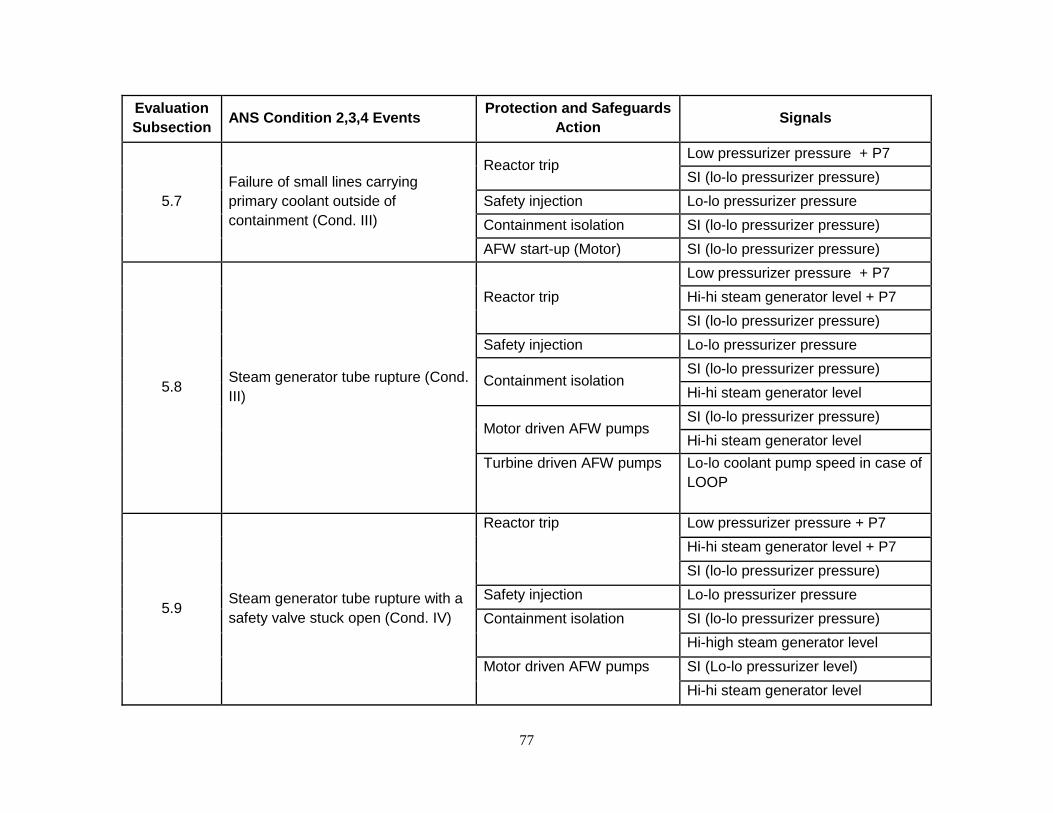
77
Evaluation
Subsection ANS Condition 2,3,4 Events
Protection and Safeguards
Action Signals
5.7
Failure of small lines carrying
primary coolant outside of
containment (Cond. III)
Reactor trip Low pressurizer pressure + P7
SI (lo-lo pressurizer pressure)
Safety injection Lo-lo pressurizer pressure
Containment isolation SI (lo-lo pressurizer pressure)
AFW start-up (Motor) SI (lo-lo pressurizer pressure)
5.8 Steam generator tube rupture (Cond.
III)
Reactor trip
Low pressurizer pressure + P7
Hi-hi steam generator level + P7
SI (lo-lo pressurizer pressure)
Safety injection Lo-lo pressurizer pressure
Containment isolation SI (lo-lo pressurizer pressure)
Hi-hi steam generator level
Motor driven AFW pumps SI (lo-lo pressurizer pressure)
Hi-hi steam generator level
Turbine driven AFW pumps Lo-lo coolant pump speed in case of
LOOP
5.9 Steam generator tube rupture with a
safety valve stuck open (Cond. IV)
Reactor trip Low pressurizer pressure + P7
Hi-hi steam generator level + P7
SI (lo-lo pressurizer pressure)
Safety injection Lo-lo pressurizer pressure
Containment isolation SI (lo-lo pressurizer pressure)
Hi-high steam generator level
Motor driven AFW pumps SI (Lo-lo pressurizer level)
Hi-hi steam generator level

78
Evaluation
Subsection ANS Condition 2,3,4 Events
Protection and Safeguards
Action Signals
Turbine driven AFW pumps Lo-lo coolant pump speed + P7
5.10
Loss of coolant accident (Cond. IV
for large breaks and intermediate
breaks – Cond. III for small breaks)
Reactor trip Low pressurizer pressure + P7
SI (high containment pressure
(MAX2))
SI (Lo-lo pressurizer pressure)
Safety injection High containment pressure (MAX2)
Lo-lo pressurizer pressure
Containment isolation SI (high containment pressure
(MAX2))
SI (Lo-lo pressurizer pressure)
AFW start-up SI (high containment pressure
(MAX2))
SI (Lo-lo pressurizer pressure)
Containment spray
High containment pressure (MAX4)

79
5.1 Feedwater System Malfunction Causing an Increase in Feedwater Flow (ANS Condition II)
Realistic assumption Scenario
Addition of excessive feedwater will result in a decrease in the primary reactor coolant
temperature and cause a subsequent increase in core power similar to the Feedwater
Temperature Decrease event (UFSAR 15.1.1). Such transients are attenuated by the thermal
capacity of the secondary plant and of the reactor coolant system. Overpower (high neutron
flux, Overtemperature T and Overpower T trips) and low pressurizer pressure protection (low
pressurizer pressure) prevent any power increase which could lead to a departure from nucleate
boiling ratio (DNBR) less than the design limit. Continuous addition of excessive feedwater is
prevented by the steam generator hi-hi level trip coincident with the P7 interlock. When the
steam generator water levels in the affected loops reach the hi-hi level setpoint, ESFAS
actuation results in the automatic closure of the main feedwater isolation valves. The feedwater
pump and discharge valves are also closed and the main feedwater pumps are tripped. This
prevents continuous addition of the feedwater.
An example of excessive feedwater flow would be the full opening of a feedwater control valve
due to a feedwater control system malfunction or an operator error. At power this excess flow
causes a greater load demand on the reactor coolant system due to increased subcooling in the
steam generator. With the plant at no-load conditions, the addition of cold feedwater may cause
a decrease in reactor coolant system temperature and thus a reactivity insertion due to the
effects of the negative MTC.
Normal reactor control systems may be credited for functioning and single active failures are not
assumed as part of the SCCF analysis. Also, the assumption that the highest-worth Rod
Control Assembly (RCA) is stuck out coincident with the reactor trip does not have to be made.
Impact of the SCCF
The Safety Injection System is not required for this event and, as a result, the subject digital
actuator is not part of the mitigation path.
5.2 Accidental Main Steam Depressurization (ANS Condition II)
Note that the evaluation of this event is for the zero power condition. The UFSAR provides the
appropriate justification to demonstrate that the at power condition is bounded by the analysis of
the Excess Load Increase event documented in the UFSAR.
Realistic assumption Scenario
This event is defined as an inadvertent opening of a single turbine bypass valve, atmospheric
steam dump valve or main steam safety valve (MSSV). This accident results in an initial
increase in steam flow, which results in an increase in the heat extraction rate and a
80
consequential reduction in primary system temperature and pressure. In the presence of a
negative MTC, the primary system cooldown results in an insertion of positive reactivity and
subsequent decrease in shutdown margin. Since the initial steam generator water inventory is
greatest at no-load, the magnitude and duration of the reactor coolant system cooldown may be
less for steam line release occurring at a just-critical or low power core condition. Additionally,
the steam flow is assumed to decrease during the accident as the steam pressure decreases.
Because the UFSAR event is initiated from the zero power condition, only ESFAS functions are
available to limit the consequence of the main steamline depressurization event by actuation of
the safety injection system, main feedwater isolation and main steamline isolation. Additionally,
the shutdown banks are assumed to be fully inserted in the core in an N-1 configuration (most
reactive rod is stuck in the fully withdrawn position) and the passive accumulators would be
available. Therefore the reactor is assumed to be in the tripped state and the reactor trip
system is not credited for actuation during the event. Additionally, a single active failure in the
ESFAS of one train of the Safety Injection system is assumed.
For the realistic assumption scenario considered here-in, neither the stuck rod nor the single
failure assumptions are required to support the SCCF evaluation. In addition, safety injection
flow rates and boron concentration levels based on realistic assumption plant data may be
assumed. The additional energy stored by various metal structures in the reactor may also be
credited to attenuate the primary reactor coolant system cooldown.
At the zero power condition, protection against an accidental depressurization of the Main
Steam System may be provided by safety injection system actuation, main feedwater isolation
and main steamline isolation. Therefore, the operators may have to manually align by using
local control the safety injection valves impacted by the actuator SCCF or wait for the RCS
pressure to decrease to the passive accumulator injection setpoint.
For an accidental depressurization of the main steam system the DNB design limits are not
exceeded. The radiological consequences of this event are not limiting in comparison to the
steam line break event.
Impact of Postulated SCCF
A review of the results of the safety analysis presented in the UFSAR indicates that the reactor
is not maintained below a critical condition throughout the event. However, the analysis credits
automatic safety injection actuation on lo-lo pressurizer pressure at 170 seconds (2.8 minutes),
which delivers boron to the core and limits the reactivity transient. Based on the use of a
realistic assumption modeling approach to address the SCCF, the elimination of the stuck rod
assumption may provide sufficient margin to prevent a return to critical condition without the
need to rely on boron delivery through actuation of the safety injection system. Further, the
severity of the inadvertent opening of a MSSV is bounded by the results for MSLB. A realistic
assumption quantitative safety analysis approach could demonstrate that acceptable results are
attained without a need for safety injection.
81
5.3 Steam System Piping Failure (ANS Condition IV)
Realistic assumption Scenario
The main steam system piping failure is the consequence of a rupture of a main steam line; the
most conservative assumption is the double ended guillotine break that leads to the greatest
cooldown. The steam release arising from a rupture of a main steam line results in an initial
increase in steam flow, which decreases during the accident as the steam pressure decreases
and the steam generator coolant inventory is depleted. This results in an increase in the
primary-to-secondary heat transfer rate and a consequential reduction in primary reactor coolant
system temperature and pressure. In the presence of a negative MTC, the cooldown results in
an insertion of positive reactivity. Initiated from an at-power condition, a steamline rupture will
result in an increase in core power due to the positive reactivity insertion. The power increase
will continue until either an equilibrium condition is reached or a reactor trip occurs. The UFSAR
Section 15.1.5 analysis assumes that the most reactive Rod Control Assembly (RCA) is stuck in
its fully withdrawn position after reactor trip, which reduces the scram reactivity worth and
increases the possibility of a post-trip return-to-power. Ultimately, the analysis demonstrates
that the event is terminated by the delivery of boric acid through safety injection actuation.
If the reactor were at hot zero power conditions at the time of the break, a continued cooldown
would normally result in safety injection actuation. In the presence of a negative moderator
temperature coefficient, the cooldown results in a reduction of core shutdown margin due to a
positive reactivity insertion from the negative MTC. The cooldown is attenuated by feedwater
isolation initiated through automatic or manual means by the operator. An automatic steamline
isolation signal will either terminate the cooldown, if the break occurs downstream of the main
steamline isolation valve (MSIV), or limit the blowdown to one steam generator if the break is
between the steam generator and the MSIV. In the event that the break occurs between the
steamline exit nozzle and the MSIV, the steam release will eventually be terminated due to the
equalization of the pressure in the faulted steam generator and containment or due to the
depletion of the coolant inventory in the faulted steam generator.
The RTS and ESFAS both function to limit the consequences of a steamline rupture event by
actuation of reactor and turbine trips, the safety injection system, feedwater isolation and
steamline isolation. Additionally, the passive accumulators provide the capability to add coolant
inventory and boron to the reactor coolant system in the event that steamline rupture results in a
large cooldown and depressurization of the reactor coolant system. With respect to the realistic
assumption evaluation, the conservative safety analysis assumptions such as a stuck RCA,
conservative reactivity feedback effects, the worst single failure or minimum safety injection
pump performance do not have to be considered to address the postulated SCCF. This lessens
the concern of achieving an over power condition at full power or a return to power from a zero
power condition.

82
With the postulated SCCF, the guidance of BTP 7-19 allows for the normal operation of control
systems. The feedwater control system may be assumed to be aligned for proper operation and
to be available for Steam Generator level control. Additionally the pressurizer pressure control
system (heaters and spray) is credited to reduce the rate of depressurization. Overall, the
combined response of the feedwater and pressurizer pressure control systems improves the
margin to fuel damage (DNBR) should a return to power be predicted.
Impact of Postulated SCCF
Since the zero power case is initiated from a post-trip condition there is no impact of the SCCF
on RTS actuations. However, safety injection, either automatic or manual, cannot be credited.
Additionally, neither the assumption of a stuck rod nor the conservatism built into the reactivity
feedback parameters have to be considered given the realistic assumption nature of this
evaluation. This lessens the concern of a post-trip return to power following a steam line
rupture. This additional negative reactivity will offset the positive reactivity inserted by the
primary system cooldown so that a return to power after a reactor trip is reduced and high local
power density near the stuck rod is removed. As such, the DNB margin would be greater than
the UFSAR case.
For the steamline rupture initiated from the full power condition, the postulated SCCF will cause
the SIS injection valves to fail. Like the zero power case, the realistic assumption quantitative
safety analysis evaluation can credit the conservatism built into the reactivity feedback
parameters, which may help reduce the magnitude of the resultant overpower condition.
5.4 Feedwater System Pipe Break (ANS Condition IV)
Realistic assumption Scenario
A major feedwater system pipe break is defined as a break in a feedwater line large enough to
prevent the addition of sufficient feedwater to the affected steam generator to maintain shell
side fluid inventory. If the break is postulated in a feedwater line between the check valve and
the steam generator, fluid from the steam generator may also be discharged through the break.
Further, a break in this location could preclude the subsequent addition of auxiliary feedwater to
the affected steam generator. The resulting depressurization induces a reversal of steam flow
from the two unaffected steam generators to the failed one. A fraction of the auxiliary feedwater
spills through the break until the auxiliary feedwater system line to the affected steam generator
is isolated. (A break upstream of the feedwater line check valve would affect the Nuclear Steam
Supply System only as a loss of feedwater to a single steam generator.) Depending upon the
size of the break and the plant operating conditions at the time of the break, the break could
cause either a reactor coolant system cooldown (by excessive energy discharge through the
break) or a reactor coolant system heatup. The maximum potential reactor coolant system
cooldown resulting from feedwater line break is bounded by the secondary pipe rupture and is
evaluated in the UFSAR, steam system piping failure. Therefore, as safety injection would not
be actuated or required to mitigate the postulated heat-up event, no further evaluation is
considered herein.

83
5.5 Inadvertent Operation of the Safety Injection System (ANS Condition II)
An Inadvertent Safety Injection event results in an unplanned or unneeded addition RCS
inventory through operation of the safety injection system. This event is currently discussed in
the UFSAR and is an ANS Condition II event. The application of digital actuators to the Safety
Injection system will not result in a change to the consequences of the event presented therein,
as it assumes a worst case scenario with respect to the RCS inventory increase. Additional
studies associated with the reliability of the proposed digital actuators would have to be
performed to determine whether or not the application of the digital actuators may result in an
increase in event frequency, such that the event may need to be reclassified as an ANS
Condition III event.
5.6 Inadvertent Opening of a Pressurizer Power Operated Relief or Safety Valve (ANS Condition II)
Realistic assumption Scenario
An accidental depressurization of the reactor coolant system could occur as a result of an
inadvertent opening of a pressurizer power operated relief or safety valve. This event results in
a rapidly decreasing reactor coolant system pressure through either the relief or safety valve.
The event is terminated by a reactor trip and stabilization of the RCS through inventory make-up
supplied by the Safety Injection system. The UFSAR event credits automatic rod control to
maintain core power and the chemical and volume control system to maintain the pressurizer
level, as these actions prolong and worsen the consequences of the event due to delaying the
reactor trip.
As the DNB concern is mitigated by a reactor trip on low pressurizer pressure and the reactor
trip setpoint is above safety injection setpoint, a SCCF associated with the safety injection valve
actuators would not impact the primary response of the RTS. Therefore, the DNBR response
would not be expected to be impacted by a failure that resulted in preventing the delivery of
Safety Injection. With respect to stabilization of the RCS pressure, if Safety Injection were not
available, the RCS pressure would decrease to the actuation setpoint of the passive
Accumulators. Once the accumulator setpoint is reached, borated RCS make-up inventory
would be injected that stabilize the RCS pressure decrease.
Impact of SCCF
Because the results of the core response are not impacted by the unavailability of Safety
Injection, the DNBR acceptance criterion would continue to be met. However, with the need to
rely on either manual operator action to align the appropriate SI valves or ensure that the
accumulators can mitigate the pressure transient, it is suggested that a realistic assumption
quantitative safety analysis be performed to demonstrate that the reactor can be placed in a
stable shutdown condition.

84
5.7 Failure of Small Lines Carrying Primary Coolant Outside Containment (ANS Condition II)
Realistic assumption Scenario
There are no instrument lines connected to the reactor coolant system that penetrate
containment. There are however, grab sample lines and one letdown line that penetrates
containment. The grab sample lines are provided with normally closed isolation valves on both
sides of the containment wall and are designed in accordance with the requirements of GDC-55.
Any release rate of these lines is within the capability of the reactor makeup system. It would
not result in ESF system actuation. Furthermore, frequent operation of the automatic makeup
system will provide the operator with some indication of the level of reactor coolant. Other
indication signals are accumulator tank level and pressure indicators, volume control tank low
level indication and alarm, containment sump level indicators, core exit thermocouples (high
reading), and stem leak-off alarms.
Impact of SCCF
The Safety Injection System is not required for this event and, as a result, reliance on the digital
actuator is not part of the mitigation path.
5.8 Steam Generator Tube Rupture (ANS Condition III)
Realistic assumption Scenario
The accident examined is the complete severance of a single steam generator tube. Timely
operator response is required to terminate the primary-to-secondary break flow and to ensure
that the ruptured steam generator does not fill with water and flood the main steam lines. This
criterion is important because the main steam lines and safety valves are not designed for liquid
flow.
The accident is assumed to take place at power with the reactor coolant contaminated with
fission products corresponding to continuous operation with a limited amount of defective fuel
rods corresponding to the Technical Specification limits. The accident leads to an increase in
contamination of the secondary system due to leakage, at the Technical Specification limits, of
radioactive coolant from the reactor coolant system. Discharge of activity can take place
through the atmosphere via the Atmospheric Steam Dump Valves and/or MSSVs. Failure of an
Atmospheric Steam Dump Valve in the open position is not assumed to occur for the realistic
assumption SCCF evaluation discussed below.
It is considered that the assumption of a complete severance of a tube is conservative and
using realistic assumptions, not likely to occur. The more probable mode of tube failure would
be one or more minor leaks of undetermined origin or a longitudinal split. Break sizes less that
the complete severance of a tube would result in lower break flow rates and subsequently
provide the operators with more time to diagnose and mitigate the event. Activity in the Steam
and Power Conversion System is subject to continual surveillance and an accumulation of minor

85
leaks which exceeds the limits established in the Technical Specifications is not permitted
during unit operation.
The major concern associated with the steam generator tube rupture and a concurrent SCCF is
the potential for the overfill condition in the faulted steam generator exceeding that analyzed in
the UFSAR safety analysis. Because the current UFSAR analysis predicts steam generator
overfill, the Atmospheric Steam Dump Valves have been qualified for water relief. Additionally,
it is noted that the MSSVs are not qualified for water relief. Further discussion of the event
assuming a SCCF is presented, below.
The operator is expected to determine that a steam generator tube rupture has occurred, and to
identify and isolate the ruptured steam generator on a restricted time scale in order to minimize
the contamination of the secondary system and to ensure the termination of the radioactive
release to the atmosphere from the ruptured steam generator. Sufficient independent and
diverse indications, alarms, procedures, controls and event specific simulator training are
provided to enable the operator to carry out these functions satisfactorily.
Consideration of the indications provided at the control board, together with the magnitude of
the break flow, leads to the conclusion that the accident diagnostics and isolation procedure can
be completed such that pressure equalization between the primary and secondary can
eventually be achieved and break flow terminated within approximately two hours using the
conservative assumptions presented in the UFSAR.
Operator actions in response to an SGTR are assumed to follow plant specific emergency
procedures and related procedures of any EOPs. Required operator action times modeled in
the plant specific UFSAR Chapter 15 analysis are typically based on plant specific operator
training sessions in the simulator following the EOPs.
Assuming normal operation of the various plant control systems, the following sequence of
events is typically initiated by a tube rupture:
1. Pressurizer low pressure and low level alarms are actuated and charging pump flow is increased to maintain pressurizer level. On the secondary side, there is a steam flow/feedwater flow mismatch prior to reactor trip as the feedwater flow to the faulted steam generator is reduced due to the break flow being supplied to that generator.
2. Decrease in pressurizer pressure due to continued loss of reactor coolant inventory leads to the generation of a reactor trip signal. Following this, the operator terminates normal feedwater supply and manually initiates auxiliary feedwater (AFW).
3. Continued loss of reactor coolant inventory may result in a reactor trip signal being generated by either Low Pressurizer Pressure (with P7 interlock), Hi-Hi Steam Generator level (with P7 interlock) or a Safety Injection signal. The resultant plant cooldown following a reactor trip leads to a rapid decrease in the pressurizer level, and the safety injection actuation signal, initiated on low-low pressurizer pressure, follows soon after the reactor trip. The safety injection system should inject borated water to the reactor coolant system via the two centrifugal charging pumps (CCPs). The safety injection actuation signal automatically causes the termination of the normal feedwater
86
supply and the initiation of the Auxiliary Feedwater System (AFS). While injection of RCS inventory is assumed to not be available due to the SCCF associated with the injection valve actuators, all other mitigating functions generated by the Safety Injection signal are assumed to be available.
4. The reactor trip automatically trips the turbine. Excess steam would be relieved through the Atmospheric Steam Dump Valves. The MSSVs would also lift if required to maintain the secondary system pressure within the acceptance criteria. The MSSVs are not qualified for water relief and would therefore be assumed to fail once the steam generator reached an overfill condition per the UFSAR analysis.
5. Following the reactor trip, the continued action of AFW provides a heat sink, which dissipates the decay heat.
The immediate symptoms of a tube rupture accident, such as falling pressurizer pressure and
level and increased charging pump flow, are also symptoms of small steamline breaks and loss
of coolant accidents. Therefore, it is important for the operator to identify the accident as a
steam generator tube rupture in order to execute the correct recovery procedure. The steam
generator tube rupture event can be uniquely identified by alarms from the condenser off gas,
steam generator blowdown, or main steamline radiation monitors. In addition, following reactor
trip, the narrow range water level will rise more rapidly in the faulted steam generator than in the
other steam generators due to the primary-to-secondary break flow.
Following identification of the event as a steam generator tube rupture, the operator responses
depicted in the UFSAR are required to terminate the primary-to-secondary break flow and to
terminate the event.
Impact of SCCF
The primary concerns for the steam generator tube rupture (SGTR) event are 1) the release of
radioactive contamination from the reactor coolant system to the secondary systems and
ultimately to the environment, and 2) overfill of the ruptured SG beyond that considered in the
UFSAR dose analysis. The primary means of protection is operator response to the symptoms
with manual actions to isolate the ruptured SG and terminate the primary to secondary release.
With the confirmation of the validity of abnormal secondary system radiation levels, the operator
would be required to actuate SI which would not cause injection due to the postulated SCCF to
the digital actuators. The diagnostic charts in the emergency procedures would guide the
operator to the appropriate emergency procedure for a steam generator tube rupture, based on
secondary radiation monitors having abnormal indications. This emergency procedure will
guide the operator through mitigation of the event. Several functions available to provide
indications of this event are steam generator blowdown and main steam line radiation monitors.
Steam generator wide range level indications will also be available to provide the operator with
indication of a steam generator tube rupture event. Other indications that can be used are
pressurizer level; reactor coolant system depressurization, main steam safety valve position,
and/or steam generator blowdown radiation monitor alarms (and indicator lights).
For evaluating the impact of SCCF on this event, the limiting single active failure (manual
termination of auxiliary feedwater from the control room, which delays termination by 15

87
minutes) does not have to be considered given the realistic assumption approach applied to the
SCCF evaluation. From the limiting case shown in the UFSAR Chapter 15 analysis, automatic
reactor/turbine trip, ECCS function, main feedwater isolation, and auxiliary feedwater initiation
are credited on the appropriate protection signals with minimum delay for the auxiliary feedwater
initiation.
ECCS during the SGTR performs two functions. It compensates for the leak flow rate and
maintains reactor coolant system inventory. It also helps to maintain reactor coolant system
subcooling. If the reactor coolant system subcooling criteria in the EOPs are not met, the
operator should proceed into the Emergency Contingency Actions involving a SGTR scenario
which has not been analyzed. It is recognized that the UFSAR analysis applies an assumption
of maximum ECCS performance, which acts to maximize the break flowrate and subsequently
maximize the resultant offsite dose calculations. For the case where ECCS is not available due
to the injection valve actuator SCCF, it is expected that the RCS pressure will naturally drift
down the point where it equalizes with the pressure in the faulted steam generator, ultimately
resulting in terminating the break flow sooner than in the UFSAR analysis. Additionally, hot leg
saturation would be a concern without the delivery of ECCS to help maintain and control RCS
pressure. It is noted that the EOPs directly monitor RCS subcooling and provide mitigating
strategies when hot leg saturation is approached, specifically tripping of the RCPs.
For the low power SGTR event, ample time should be available for the operator to manually
isolate main feedwater and trip the reactor due to the smaller primary-to-secondary pressure
and temperature differences. Additionally, the ability to maintain subcooling in the core is eased
due to the low power level. Diverse indications are available that indicate the need for these
actions. Therefore a realistic assumption quantitative analysis is suggested to ensure that
sufficient time exists for manual operator action, define whether or not the Atmospheric Steam
Dump Valves are required to mitigate a steam generator overfill condition, ensure that the
accumulators can provide a sufficient capability to maintain primary reactor coolant system
inventory and subcooling, and define any required diverse automatic RTS and ESFAS functions
if insufficient time is available to credit operator action.
For the full power SGTR event, ECCS flow is required to be actuated by manual operator
actuation within approximately 10 minutes of identification of the SGTR event. Therefore, a
realistic assumption quantitative analysis should be performed to address the situation where
automatic SIS injection is not available and ensure that the resultant mass release used in the
UFSAR dose analysis remains bounding.
5.9 Steam Generator Tube Rupture with a Safety Valve Stuck Open
Per the guidance provided in BTP 7-19, the limiting failure does not have to be assumed
concurrently with the event and the postulated SCCF for the SCCF evaluation. As a result, the
Steam Generator Tube Rupture event with a Stuck Open Main Steam Safety Valve does not
require evaluation in the Diversity and Defense In-Depth SCCF analysis.

88
5.10 Loss of Coolant Accident (LOCA) (ANS Condition III for Small Breaks, ANS Condition IV for Large Breaks and Intermediate Breaks)
Realistic assumption Scenario
A Loss of Coolant Accident (LOCA) is the result of a pipe rupture of the reactor coolant system
pressure boundary. The UFSAR discusses a spectrum of break sizes. The limiting break
location is in the cold leg piping for all break sizes. The UFSAR discusses large break LOCAs
and small break LOCAs separately, because the phenomena and analysis methods are
different for these break classifications.
The acceptance criteria for this event are from 10CFR50.46 and are:
a. The calculated peak fuel element clad temperature should be below 1204°C. b. The amount of fuel element cladding that reacts chemically with water or steam
should not exceed 1% of the total amount of Zircaloy/Zirlo in the reactor. c. The localized cladding oxidation should be less than 17%. d. The core must remain in a coolable geometry at all times. e. Long term cooling of the core should be ensured.
The analyses described in the UFSAR show that the above criteria are satisfied for Hawke River
for the complete spectrum of break sizes. The limiting large break LOCA is a double-ended
guillotine break in the cold leg. The limiting small break LOCA is in the cold leg. The large
break LOCA results in higher peak cladding temperatures than the small break LOCA. Hence it
is the limiting event supporting the design basis of the ECCS.
The large break LOCA also is the limiting event for the peak pressure analysis in the
containment and supports the design basis for the containment function.
The UFSAR LOCA analyses assume a loss of offsite power concurrent with break initiation and
a single failure of a low head safety injection pump. The analyses also assume conservative
initial and boundary conditions. Qualitatively, the sequence of events for a LOCA will not be
significantly different with more realistic accident assumptions. The main change is that a loss
of offsite power does not need to be assumed in a realistic scenario. The reactor coolant
pumps would not be tripped at the beginning of the accident, and the operator would trip them
when the appropriate setpoint (subcooling margin) is reached as dictated by the EOPs.
In a realistic scenario, for large break LOCAs, the reactor coolant system will depressurize
rapidly immediately after break initiation. A reactor trip signal will be initiated by a low
pressurizer pressure signal. This will be followed quickly by a safety injection actuation signal,
which activates the ECCS. The reactor coolant pumps continue to operate until the operator
trips them on a loss of subcooling margin. The rapid depressurization results in core voiding,
which introduces substantial negative reactivity in the core causing a rapid power decrease.
The UFSAR analysis assumes that control rods do not insert for this accident, demonstrating
that the negative reactivity introduced by core voiding is more than sufficient to decrease reactor
power to manageable levels. The accumulators begin injecting water when the reactor coolant

89
system pressure drops to about 600 psia. The core is maintained in a shutdown condition due
to boron delivery from both the ECCS and the accumulators.
In the UFSAR analysis, because of the assumed loss of offsite power, there is a delay for the
diesels to come up to speed. This causes a small delay in ECCS injection. In any case the
High Pressure ECCS injection begins first followed by the Low Pressure ECCS injection. The
UFSAR analysis indicates that peak cladding temperatures in the core are reached in the time
period of 2 to 3 minutes after break initiation. The core temperature increase is arrested
primarily due to the water injected by the Low Pressure ECCS injection system. Subsequently,
the core is refilled as the Low Pressure ECCS injection system continues to inject water. The
injected ECCS water is borated, and this provides sufficient negative reactivity to maintain the
core subcritical. Beyond this time, long term recovery procedures will be active and this
maintains the core filled and in a coolable geometry. These longer term recovery actions, such
as switchover to ECCS recirculation from the containment sump, are manual operator actions
based on the plants emergency operating procedures. These long term actions are well beyond
the manual ESFAS action times considered herein and therefore beyond the scope of the SCCF
evaluation.
As contrasted with the large break, the blowdown phase of the small break occurs over a longer
time period. For very small breaks, the charging pumps can make up water to maintain the
reactor coolant system at its initial operating condition, until the operator responds to the event
and initiates an orderly shutdown. The UFSAR notes that for Hawke River, one charging pump
can provide makeup flow to the reactor coolant system to maintain the system pressure at the
normal operating pressure.
For larger small breaks, the reactor coolant system depressurizes resulting in a reactor trip on
low pressurizer pressure and safety system activation on low-low pressurizer pressure. Prior to
the reactor trip, it is possible for the power to increase slightly. This is because there can be a
small positive reactivity insertion due to the nature of the moderator density reactivity coefficient.
As density continues to decrease the reactivity becomes more negative and the power
decreases. As the depressurization continues, if the break size is small enough, high pressure
injection from the ECCS provides sufficient makeup. In this case, the reactor coolant system
pressure stabilizes and there is no resultant core uncovering. For the larger end of the small
break spectrum, the depressurization continues. As the reactor coolant system continues to
depressurize further, the low pressure ECCS injection initiates and provides continued core
cooling. At a pressure of approximately 600 psia, the cold leg accumulators begin to inject
borated water. Meanwhile, it is possible for the core to void partially and exhibit some fuel rod
heatup. However, for all small breaks, the combination of ECCS and accumulator injection
provides sufficient water supply to maintain the mixture above the top of the core. Eventually,
similar to the large break LOCA which is discussed below, long term recovery procedures are
established following the EOPs.
Impact of SCCF

90
A concurrent event such as a loss of offsite power is not assumed for the SCCF analysis;
therefore, the reactor coolant pumps are not assumed to trip at the inception of the accident.
The primary automatic RTS trip signal is low pressurizer pressure for the LOCA events. The
backup reactor trip signals are containment high-pressure safety injection and OTDT. The
primary ESFAS safety function is provided by the ECCS to provide safety injection on a low-low
pressurizer pressure signal. The SIS fails to inject water for all size breaks into the reactor due
to the SCCF of the digital actuators. However, the auxiliary feedwater actuates.
The current UFSAR analysis does not credit the shutdown control rod banks. The reactor
power is decreased initially due to the large negative reactivity introduced by core voiding, and
the core is maintained subcritical at later times due to Boron injection from the ECCS and
accumulators. For the larger end of the small break spectrum and the intermediate breaks, the
cases initially result in core voiding and subsequent Boron delivery from the ECCS and
accumulator actuation. In the initial phase of a small break LOCA, due to the moderator density
coefficient, the reactor power would increase slightly. This power excursion is mitigated by the
negative Doppler reactivity provided by an increase in fuel temperature. As the small break
LOCA event progresses, with an attendant decrease in reactor coolant system pressure, the
moderator density decreases, and combined with the negative fuel temperature coefficient,
provides sufficient negative reactivity to begin decreasing reactor power. Since offsite power is
available, the reactor coolant pumps continue to operate, providing forced coolant flow through
the core. The reactor coolant pumps are tripped if the operator is directed to do so as directed
by the EOPs. However, prior to tripping the pumps, the operator would manually trip the reactor
if an automatic trip signal were not generated. This should not result in violations of the realistic
assumption acceptance criteria.
If ECCS flow cannot be automatically established, there will be a significant effect on the large
break LOCA scenario. The UFSAR analysis shows that the peak cladding temperatures are
reached in a short period of time (1 to 2 minutes) after break initiation. This means that ECCS
actuation is required in a similar 1 to 2 minute time frame to mitigate the event and provide a
coolant source to begin recovery the core water level. Also, the rate of cladding temperature
increase will be slightly lower based on a set of realistic assumptions, power distribution peaking
factors and decay heat. Nevertheless, further evaluation is needed to determine whether the
time available for the operator to diagnose and respond to this event is sufficient to maintain the
peak cladding temperatures within acceptable limits. It is likely that the operator must act within
the first minute following event initiation to provide successful mitigation for this event. (System
level manual SIS injection actuation is impaired due to the SCCF for the digital actuators.
However, the operator can manually operate each valve from a local control station.) This will
prove to be the limiting case and will require implementation of a design change to successfully
mitigate the LBLOCA event.
6 Diverse Mitigating Functions for FSAR Chapter 15 Accident Analyses
The evaluation considered that the plant response to the postulated initiating events (PIE)
concurrent with a postulated CCF can be addressed by one of the following approaches. These

91
approaches can be categorized in different ways but for this evaluation, the following four
categories were chosen:
Category A – The Safety Injection System is not required to be actuated in the event,
resulting in no impact from the postulated digital actuator SCCF or the
event is not considered in the SCCF evaluation because multiple failures
would be required in order for the event to occur.
Category B – The event is terminated successfully by actuation of RTS and/or ESFAS
or an alternate, independent, diverse system through either automatic or
manual actions. The events credited with mitigation through the use of
manual actions for mitigation were deemed acceptable and placed into
this category if an engineering analysis determined there was sufficient
time and available indications available.
Category C – The event is bounded by another event.
Category D – Further work is required to demonstrate successful event mitigation, such
as quantitative analysis, event simulations, additional justifications, or
plant modifications. The final results of this work action would be to
change the Category D items to Category B either by the acceptance of a
manual actuation(s) or the addition of the proper diverse mitigation
functions through a diverse actuation system (DAS).
Indicators and alarms for events requiring operator manual action are provided by highly reliable
components. Should an event occur, these indicators and alarms will be available to alert the
operator so that timely and appropriate operator action for the applicable events can be taken in
accordance with plant procedures. The following criteria were used to consider if operator
manual action was credible:
The postulated digital actuator SCCF and its effects do not impair controls or displays necessary for operator action,
Sufficient information is available for the operator to determine the action required, and
Sufficient time is available for operator analysis, decisions and action.
Table 2 below shows the resulting Category D for each event. For this example, only the
Category D events are shown in Table 2. With the exception of the LBLOCA, these events could
be placed into Category B by using a more detailed quantitative analysis showing positive
results. However, the LBLOCA event requires design changes as noted above. All the Hawke
River events described will continue to meet established acceptance criteria using realistic
assumption assessments with equivalent protection or mitigation functions providing design
changes are made as recommended.

92
Table 2 Category D– Chapter 15 Events Requiring Further Analysis
No. PIE PRIMARY PROTECTION DIVERSE
PROTECTION*
5.2 Accidental Main Steam System
Depressurization
Safety Injection
Containment Isolation
AFW
Steam Line Isolation
SI-Low-Low Press
SI
SI
Lo-Lo STG Press
5.3 Steam System Piping Failure Safety Injection
Containment Isolation
AFW
Steam Line Isolation
Containment Spray
Low Compensated
SP
SI
SI
Low Compensate SP
Hi Containment
Pressure
5.6 Opening PSV Reactor Trip
Safety Injection
Containment Isolation
AFW Start-up
SI - Low-Low
Pressurizer Pressure
5.8 SGTR Reactor Trip
Safety Injection
Containment Isolation
Motor driven AFW pumps
Manual Operator
action
SI - Low-Low
Pressurizer Pressure
5.10 LOCA (Large, intermediate and
small)
Reactor Trip
Safety Injection
Containment Isolation
AFW Start-up
Containment Spray
SI – Low-Low
Pressurizer Pressure

93
6 Conclusions
The Hawke River licensing basis safety analyses were evaluated to determine which events
required the SIS for primary or backup protection actuations. Those events identified as
requiring the SIS for primary/secondary protection system response were then evaluated to
determine if a timely diverse means of automatically mitigating the transient was available or
annunciators and indicators were available to allow the operator to diagnose the event and
manually bring the plant to a safe shutdown condition in a timely manner. Manual actuations for
the SIS can only be considered at the local valve control as the system level manual mitigation
path required use of the digital actuators which are postulated to have failed due to the SCCF.
This evaluation yielded 5 Category D events causing concern and requiring more detailed
quantitative evaluations. However, the LBLOCA event will prove to be bounding as discussed
below.
The Hawke River D3 evaluation documented herein has demonstrated that there is a concern
with sufficient diversity and defense-in-depth to cope with a postulated SCCF to the SIS digital
actuators. It has been determined that, with a postulated SCCF there are not adequate
defenses and diversity in the SIS architecture to meet the applicable acceptance criteria. The
LBLOCA will prove to be the limiting case and cannot be successfully mitigated without a design
change to cope with the postulated SCCF.
This change should be one of the following:
1. Software for the digital actuators be completely testable (simple software) in accordance with NRC guidance such that a SCCF possibility is eliminated
2. Diverse digital actuators would be needed for each SIS Train to eliminate concurrent SCCFs to both digital actuators.
3. Either maintain the current analog actuators or replace them (if available) with new analog actuators which are not susceptible to the SCCF concern.
When considering realistic assumption and the design of the digital actuators, it is determined
that the proposed Hawke River digital I&C architecture will meet the BTP 7-19 acceptance
criteria with the implementation of one of the three options noted above.
Each initiating event requiring SIS was evaluated using qualitative deterministic methods. Based
on the evaluation herein, it is expected that the acceptance criteria as discussed in the
qualification section of this report will be met for all evaluated PIEs when the actuator design
modification as discussed above is implemented. That this conclusion applies to the proposed
SIS design is demonstrated in the evaluations shown in this appendix, which assumes that a
SCCF disables the digital actuation portion of the SIS design while all other systems, including
ATWS and the other SIS functions, are not susceptible to the same SIS digital actuator SCCF
and remain available to perform the required functions.