differential and driveline - · pdf file03/02/2017 · differential and driveline...
TRANSCRIPT

11
G
D
S
G
P
pdt
smlpsgtsy
u
TJ DIFFERENTIAL AND DRIVELINE 3 - 1
DIFFERENTIAL AND DRIVELINE
CONTENTS
page page
81 FBI AXLE . . . . . . . . . . . . . . . . . . . . . . . . . . . 1594 RBI AXLE . . . . . . . . . . . . . . . . . . . . . . . . . . . 49
page
PROPELLER SHAFT ANGLE MEASUREMENT . . . 6
R
D
C
A
S
S
216 RBI REAR AXLE . . . . . . . . . . . . . . . . . . . . . . 84PROPELLER SHAFTS . . . . . . . . . . . . . . . . . . . . . . 1
PROPELLER SHAFTS
INDEX
page
ENERAL INFORMATIONLUBRICATION . . . . . . . . . . . . . . . . . . . . . . . . . . . 2PRECAUTIONS . . . . . . . . . . . . . . . . . . . . . . . . . . 3PROPELLER SHAFT JOINT ANGLE . . . . . . . . . . . 2PROPELLER SHAFT JOINTS . . . . . . . . . . . . . . . . 1PROPELLER SHAFTS . . . . . . . . . . . . . . . . . . . . . 1IAGNOSIS AND TESTINGRUNOUT . . . . . . . . . . . . . . . . . . . . . . . . . . . . . . . 5UNBALANCE . . . . . . . . . . . . . . . . . . . . . . . . . . . . 4VIBRATION . . . . . . . . . . . . . . . . . . . . . . . . . . . . . 3ERVICE PROCEDURESDRIVELINE ANGLE MEASUREMENT
PREPARATION . . . . . . . . . . . . . . . . . . . . . . . . . 6
EMOVAL AND INSTALLATIONFRONT PROPELLER SHAFT . . . . . . . . . . . . . . . . 8REAR PROPELLER SHAFT . . . . . . . . . . . . . . . . . 8ISASSEMBLY AND ASSEMBLYDOUBLE CARDAN JOINT . . . . . . . . . . . . . . . . . 10SINGLE CARDAN UNIVERSAL JOINT . . . . . . . . . 9LEANING AND INSPECTIONSINGLE AND DOUBLE CARDAN JOINT . . . . . . . 13DJUSTMENTSAXLE PINION ANGLE ADJUSTMENT . . . . . . . . . 13PECIFICATIONSTORQUE . . . . . . . . . . . . . . . . . . . . . . . . . . . . . . 14PECIAL TOOLS
PROPELLER SHAFT . . . . . . . . . . . . . . . . . . . . . 14ENERAL INFORMATION
ROPELLER SHAFTSThe function of a propeller shaft is to transmit
ower from one point to another. The shaft isesigned to send torque from the transmission andransfer case to the drive axles (Fig. 1).
The propeller shaft must operate through con-tantly changing relative angles between the trans-ission and axle. It must also be capable of changing
ength while transmitting torque. The axle rides sus-ended by springs in a floating motion. The propellerhaft must be able to change operating angles whenoing over various road surfaces. This is donehrough universal joints, which permit the propellerhaft to operate at different angles. The slip joints (orokes) permit contraction or expansion (Fig. 1).Tubular propeller shafts are balanced by the man-
facturer with weights spot welded to the tube.
The propeller shaft is designed and built with theyoke lugs in line with each other which is called zerophasing. This design produces the smoothest runningcondition, an out-of-phase shaft can cause a vibra-tion.
Before undercoating a vehicle, the propellershaft and the U-joints should be covered ot pre-vent an out-of-balance condition and drivelinevibration.
CAUTION: Use original equipment replacementparts for attaching the propeller shafts. The speci-fied torque must always be applied when tighteningthe fasteners.
PROPELLER SHAFT JOINTSTwo different types of propeller shaft joints are
used in TJ vehicles (Fig. 2) and (Fig. 3). None of thejoints are servicible. If worn or damaged, they mustbe replaced as a complete assembly.

P
tTlscd
elle
3 - 2 DIFFERENTIAL AND DRIVELINE TJ
GENERAL INFORMATION (Continued)
ROPELLER SHAFT JOINT ANGLEWhen two shafts come together at a common joint,
he bend that is formed is called the operating angle.he larger the angle, the larger the amount of angu-
ar acceleration and deceleration of the joint. Thispeeding up and slowing down of the joint must beancelled to produce a smooth power flow. This isone through the phasing of a propeller shaft and
Fig. 1 Prop
Fig. 2 Single Cardan U-Joint
ensuring that the proper propeller shaft joint work-ing angles are maintained.
A propeller shaft is properly phased when the yokeends are in the same plane, or in line. A twistedshaft will make the yokes out of phase and cause anoticeable vibration.
When taking propeller shaft joint angle measure-ments, or checking the phasing, of two piece shafts,consider each shaft separately.
Ideally the driveline system should have;• Angles that are equal or opposite within 1
degree of each other.• Have a 3 degree maximum operating angle.• Have at least a 1/2 degree continuous operating
(propeller shaft) angle.Engine speed (rpm) is the main factor in determin-
ing the maximum allowable operating angle. As aguide to the maximum normal operating angles referto (Fig. 4).
LUBRICATIONThe factory installed universal joints are lubricated
for the life of the vehicle and do not need lubrication.All universal joints should be inspected for leakageand damage each time the vehicle is serviced. If sealleakage or damage exists, the universal joint shouldbe replaced.
r Shafts
P
tmeo
tyb
Coru
Car
TJ DIFFERENTIAL AND DRIVELINE 3 - 3
GENERAL INFORMATION (Continued)
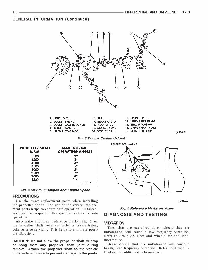
RECAUTIONSUse the exact replacement parts when installing
he propeller shafts. The use of the correct replace-ent parts helps to ensure safe operation. All fasten-
rs must be torqued to the specified values for safeperation.Also make alignment reference marks (Fig. 5) on
he propeller shaft yoke and axle, or transmission,oke prior to servicing. This helps to eliminate possi-le vibration.
AUTION: Do not allow the propeller shaft to dropr hang from any propeller shaft joint duringemoval. Attach the propeller shaft to the vehiclenderside with wire to prevent damage to the joints.
Fig. 3 Double
Fig. 4 Maximum Angles And Engine Speed
DIAGNOSIS AND TESTING
VIBRATIONTires that are out-of-round, or wheels that are
unbalanced, will cause a low frequency vibration.Refer to Group 22, Tires and Wheels, for additionalinformation.
Brake drums that are unbalanced will cause aharsh, low frequency vibration. Refer to Group 5,Brakes, for additional information.
Fig. 5 Reference Marks on Yokes
dan U-Joint

df
s
U
Nsv
i
l
wp
3 - 4 DIFFERENTIAL AND DRIVELINE TJ
DIAGNOSIS AND TESTING (Continued)
Driveline vibration can also result from loose oramaged engine mounts. Refer to Group 9, Engines,or additional information.
Propeller shaft vibration increases as the vehicle
peed is increased. A vibration that occurs within aspecific speed range is not usually caused by a pro-peller shaft being unbalanced. Defective universaljoints, or an incorrect propeller shaft angle, are usu-ally the cause of such a vibration.
DRIVELINE VIBRATION
Drive Condition Possible Cause Correction
Propeller Shaft Noise 1) Undercoating or other foreignmaterial on shaft.
1) Clean exterior of shaft and washwith solvent.
2) Loose U-joint clamp screws. 2) Install new clamps and screwsand tighten to proper torque.
3) Loose or bent U-joint yoke orexcessive runout.
3) Install new yoke.
4) Incorrect driveline angularity. 4) Measure and correct drivelineangles.
5) Rear spring center bolt not inseat.
5) Loosen spring u-bolts and seatcenter bolt.
6) Worn U-joint bearings. 6) Install new U-joint.
7) Propeller shaft damaged or outof balance.
7) Installl new propeller shaft.
8) Broken rear spring. 8) Install new rear spring.
9) Excessive runout or unbalancedcondition.
9) Re-index propeller shaft 180°,test, and evaluate.
10) Excessive drive pinion gearshaft runout.
10) Re-index propeller shaft 180°and evaluate.
11) Excessive axle yoke deflection. 11) Inspect and replace yoke ifnecessary.
12) Excessive transfer case runout. 12) Inspect and repair as necessary.
Universal Joint Noise 1) Loose U-joint clamp screws. 1) Install new clamps and screwsand tighten to proper torque.
2) Lack of lubrication. 2) Lubricate U-joint and evaluate.Replace as necessary.
NBALANCE
OTE: Removing and re-indexing the propellerhaft 180° relative to the yoke may eliminate someibrations.
If propeller shaft is suspected of being unbalanced,t can be verified with the following procedure:
(1) Raise the vehicle.(2) Clean all the foreign material from the propel-
er shaft and the universal joints.(3) Inspect the propeller shaft for missing balanceeights, broken welds, and bent areas. If the pro-eller shaft is bent, it must be replaced.
(4) Inspect the universal joints to ensure that theyare not worn, are properly installed, and are cor-rectly aligned with the shaft.
(5) Check the universal joint clamp screws torque.(6) Remove the wheels and tires. Install the wheel
lug nuts to retain the brake drums or rotors.(7) Mark and number the shaft six inches from the
yoke end at four positions 90° apart.(8) Run and accelerate the vehicle until vibration
occurs. Note the intensity and speed the vibrationoccurred. Stop the engine.
(9) Install a screw clamp at position 1 (Fig. 6).(10) Start the engine and re-check for vibration. If
there is little or no change in vibration, move the

cv
ob
c
vb
aas
t
TJ DIFFERENTIAL AND DRIVELINE 3 - 5
DIAGNOSIS AND TESTING (Continued)
lamp to one of the other three positions. Repeat theibration test.(11) If there is no difference in vibration at the
ther positions, the source of the vibration may note propeller shaft.(12) If the vibration decreased, install a second
lamp (Fig. 7) and repeat the test.
(13) If the additional clamp causes an additionalibration, separate the clamps (1/4 inch above andelow the mark). Repeat the vibration test (Fig. 8).(14) Increase distance between the clamp screws
nd repeat the test until the amount of vibration ist the lowest level. Bend the slack end of the clampso the screws will not loosen.(15) If the vibration remains unacceptable, apply
he same steps to the front end of the propeller shaft.(16) Install the wheel and tires. Lower the vehicle.
Fig. 6 Clamp Screw At Position 1
Fig. 7 Two Clamp Screws At The Same Position
RUNOUT(1) Remove dirt, rust, paint, and undercoating
from the propeller shaft surface where the dial indi-cator will contact the shaft.
(2) The dial indicator must be installed perpendic-ular to the shaft surface.
(3) Measure runout at the center and ends of theshaft sufficiently far away from weld areas to ensurethat the effects of the weld process will not enter intothe measurements.
(4) Refer to Runout Specifications chart.(5) If the propeller shaft runout is out of specifica-
tion, remove the propeller shaft, index the shaft 180°,and re-install the propeller shaft. Measure shaftrunout again.
(6) If the propeller shaft runout is now withinspecifications, mark the shaft and yokes for properorientation.
(7) If the propeller shaft runout is not within spec-ifications, verify that the runout of the transmission/transfer case and axle are within specifications.Correct as necessary and re-measure propeller shaftrunout.
(8) Replace the propeller shaft if the runout stillexceeds the limits.
Fig. 8 Clamp Screws Separated
RUNOUT SPECIFICATIONS
Front of Shaft 0.020 in. (0.50 mm)
Center of Shaft 0.025 in. (0.63 mm)
Rear of Shaft 0.020 in. (0.50 mm)
Measure front/rear runout approximately 3 inches (76mm) from the weld seam at each end of the shafttube for tube lengths over 30 inches. For tube lengthsunder 30 inches, the maximum allowed runout is0.020 in. (0.50 mm) for the full length of the tube.

S
DP
l
uPa
nc
ss
P
sA
ef
c
rwc
tr
s
I(ma
S
A
Isr
s
3 - 6 DIFFERENTIAL AND DRIVELINE TJ
ERVICE PROCEDURES
RIVELINE ANGLE MEASUREMENTREPARATIONBefore measuring universal joint angles, the fol-
owing must be done;• Inflate all tires to correct pressure.• Check the angles in the same loaded or
nloaded condition as when the vibration occurred.ropeller shaft angles change according to themount of load in the vehicle.• Check the condition of all suspension compo-
ents and verify all fasteners are torqued to specifi-ations.• Check the condition of the engine and transmis-
ion mounts and verify all fasteners are torqued topecifications.
ROPELLER SHAFT ANGLE MEASUREMENTTo accurately check driveline alignment, raise and
upport the vehicle at the axles as level as possible.llow the wheels and propeller shaft to turn.(1) Remove any external bearing snap rings, if
quipped, from universal joint so protractor base sitslat.
(2) Rotate the shaft until transmission/transferase output yoke bearing is facing downward.Always make measurements from front to
ear. Also, be sure to take all measurementshile working from the same side of the vehi-
le.(3) Place Inclinometer on yoke bearing (A) parallel
o the shaft (Fig. 9). Center bubble in sight glass andecord measurement.This measurement will give you the transmis-
ion or Output Yoke Angle (A).(4) Rotate propeller shaft 90 degrees and place
nclinometer on yoke bearing parallel to the shaftFig. 10). Center bubble in sight glass and recordeasurement. This measurement can also be taken
t the rear end of the shaft.This measurement will give you the Propeller
haft Angle (C).(5) Subtract smaller figure from larger (C minus) to obtain Transmission Output Operating Angle.(6) Rotate propeller shaft 90 degrees and place
nclinometer on pinion yoke bearing parallel to thehaft (Fig. 11). Center bubble in sight glass andecord measurement.This measurement will give you the pinion
haft or Input Yoke Angle (B).
(7) Subtract smaller figure from larger (C minusB) to obtain axle Input Operating Angle.
Refer to rules given below and the example in (Fig.12) for additional information.
• Good cancellation of U–joint operating angles(within 1°).
• Operating angles less than 3°.• At least 1/2 of one degree continuous operating
(propeller shaft) angle.
Fig. 9 Front (Output) Angle Measurement (A)
Fig. 10 Propeller Shaft Angle Measurement (C)

TJ DIFFERENTIAL AND DRIVELINE 3 - 7
SERVICE PROCEDURES (Continued)
Fig. 11 Rear (Input) Angle Measurement (B)
Fig. 12 Universal J
oint Angle Example
R
F
R
e
tps
t
s
t
t
t
I
w
y
j
t
o
a
3 - 8 DIFFERENTIAL AND DRIVELINE TJ
EMOVAL AND INSTALLATION
RONT PROPELLER SHAFT
EMOVAL
(1) Hoist and support vehicle on safety stands.(2) Shift the transmission and transfer case, if nec-
ssary, into the Neutral position.(3) Using a suitable marker, mark a line across
he yoke at the transfer case, the link yoke, and pro-eller shaft yoke at the rear of the front propellerhaft for installation reference (Fig. 14).(4) Mark a line across the propeller shaft yoke and
he pinion shaft yoke for installation reference.(5) Remove the U-joint strap bolts at the pinion
haft yoke.(6) Remove bolts holding rear universal joint to
he transfer case yoke.(7) Separate the rear universal joint from the
ransfer case yoke.(8) Push rear of propeller shaft upward to clear
ransfer case yoke.(9) Separate front universal joint from front axle.(10) Separate propeller shaft from vehicle.
NSTALLATION(1) Position front propeller shaft under vehicleith rear universal joint over the transfer case yoke.(2) Place front universal joint into the axle pinion
oke.(3) Align mark on the rear link yoke and universal
oint to the mark on the transfer case yoke (Fig. 14).(4) Loosely install bolts to hold universal joint to
ransfer case yoke.(5) Align mark on front universal joint to the mark
n the axle pinion yoke.(6) Tighten the U-joint strap/clamp bolts at the
xle yoke to 19 N·m (14 ft. lbs.) torque.
Fig. 13 Front Propeller Shaft
(7) Tighten the universal joint to transfer casebolts to 27 N·m (20 ft. lbs.) torque.
(8) Lower the vehicle.
REAR PROPELLER SHAFT
REMOVAL(1) Shift the transmission and transfer case into
Neutral.(2) Hoist and support vehicle on safety stands.(3) Scribe alignment marks at the pinion shaft and
at each end of the propeller shaft. These marks willbe used for installation reference.
(4) Remove the U-joint strap bolts at the pinionshaft yoke.
(5) Pry open clamp holding the dust boot to propel-ler shaft yoke (Fig. 15).
(6) Slide the slip yoke off of the transmission/transfer case output shaft and remove the propellershaft (Fig. 16).
Fig. 14 Reference Marks on Yokes
Fig. 15 Dust Boot Clamp
I
cm(
a
s
D
S
D
ar
i
TJ DIFFERENTIAL AND DRIVELINE 3 - 9
REMOVAL AND INSTALLATION (Continued)
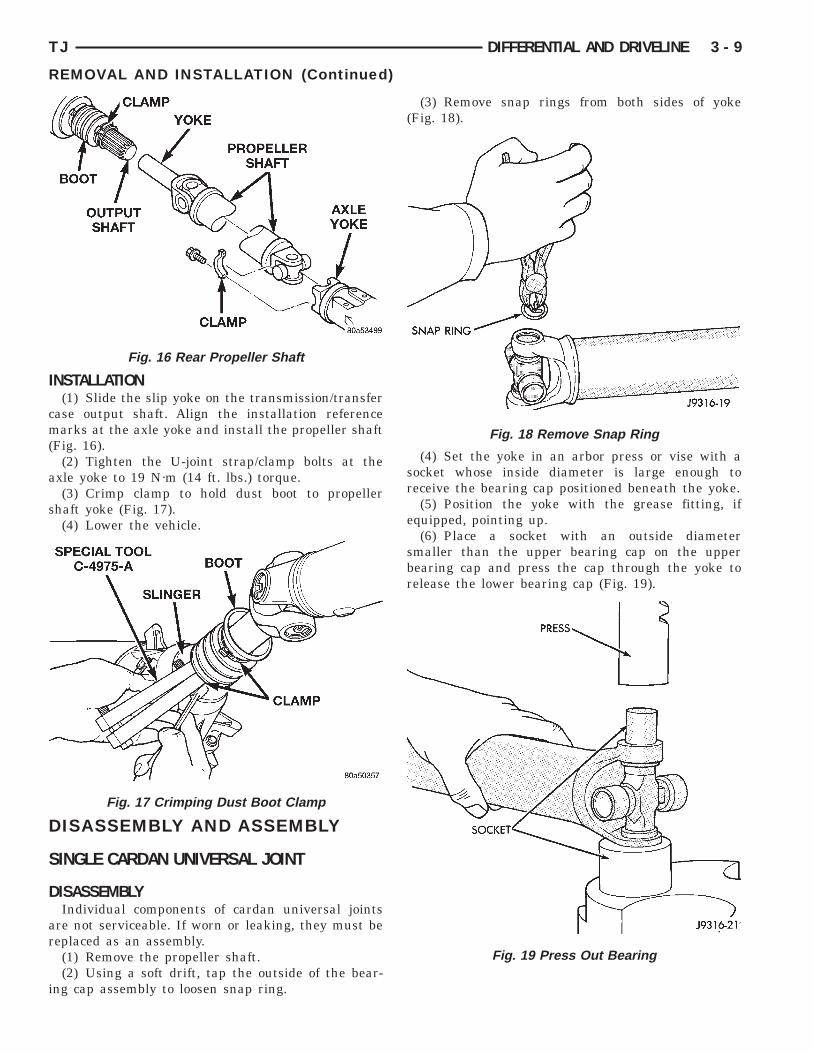
NSTALLATION(1) Slide the slip yoke on the transmission/transfer
ase output shaft. Align the installation referencearks at the axle yoke and install the propeller shaft
Fig. 16).(2) Tighten the U-joint strap/clamp bolts at the
xle yoke to 19 N·m (14 ft. lbs.) torque.(3) Crimp clamp to hold dust boot to propeller
haft yoke (Fig. 17).(4) Lower the vehicle.
ISASSEMBLY AND ASSEMBLY
INGLE CARDAN UNIVERSAL JOINT
ISASSEMBLYIndividual components of cardan universal joints
re not serviceable. If worn or leaking, they must beeplaced as an assembly.(1) Remove the propeller shaft.(2) Using a soft drift, tap the outside of the bear-
ng cap assembly to loosen snap ring.
Fig. 16 Rear Propeller Shaft
Fig. 17 Crimping Dust Boot Clamp
(3) Remove snap rings from both sides of yoke(Fig. 18).
(4) Set the yoke in an arbor press or vise with asocket whose inside diameter is large enough toreceive the bearing cap positioned beneath the yoke.
(5) Position the yoke with the grease fitting, ifequipped, pointing up.
(6) Place a socket with an outside diametersmaller than the upper bearing cap on the upperbearing cap and press the cap through the yoke torelease the lower bearing cap (Fig. 19).
Fig. 18 Remove Snap Ring
Fig. 19 Press Out Bearing

bb
yTr
Csso
A
ot
t
annp
e
sti
3 - 10 DIFFERENTIAL AND DRIVELINE TJ
DISASSEMBLY AND ASSEMBLY (Continued)
(7) If the bearing cap will not pull out of the yokey hand after pressing, tap the yoke ear near theearing cap to dislodge the cap.(8) To remove the opposite bearing cap, turn the
oke over and straighten the cross in the open hole.hen, carefully press the end of the cross until theemaining bearing cap can be removed (Fig. 20).
AUTION: If the cross or bearing cap are nottraight during installation, the bearing cap willcore the walls of the yoke bore and damage canccur.
SSEMBLY(1) Apply extreme pressure (EP) N.L.G.I. Grade 1
r 2 grease to inside of yoke bores to aid in installa-ion.
(2) Position the cross in the yoke with its lube fit-ing, if equipped, pointing up (Fig. 21).
(3) Place a bearing cap over the trunnion andlign the cap with the yoke bore (Fig. 22). Keep theeedle bearings upright in the bearing assembly. Aeedle bearing lying at the bottom of the cap willrevent proper assembly.(4) Press the bearing cap into the yoke bore
nough to install a snap ring.(5) Install a snap ring.(6) Repeat Step 3 and Step 4 to install the oppo-
ite bearing cap. If the joint is stiff or binding, strikehe yoke with a soft hammer to seat the needle bear-ngs.
(7) Add grease to lube fitting, if equipped.(8) Install the propeller shaft.
Fig. 20 Press Out Remaining Bearing
DOUBLE CARDAN JOINT
DISASSEMBLYIndividual components of cardan universal joints
are not serviceable. If worn or leaking, they must bereplaced as an assembly.
(1) Remove the propeller shaft.(2) Using a soft drift, tap the outside of the bear-
ing cap assembly to loosen snap ring.
Fig. 21 Install Cross In Yoke
Fig. 22 Install Bearing On Trunnion

2
sry
sbttr
TJ DIFFERENTIAL AND DRIVELINE 3 - 11
DISASSEMBLY AND ASSEMBLY (Continued)
(3) Remove all the bearing cap snap rings (Fig.3).
(4) Set the joint in an arbor press or vise with aocket whose inside diameter is large enough toeceive the bearing cap positioned beneath the linkoke.(5) Place a socket with an outside diameter
maller than the upper bearing cap on the upperearing cap and partially press one bearing cap fromhe outboard side of the link yoke enough to grasphe bearing cap with vise jaws (Fig. 24). Be sure toemove grease fittings that interfere with removal.
Fig. 23 Remove Snap Rings
Fig. 24 Press Out Bearing
(6) Grasp the protruding bearing by vise jaws. Tapthe link yoke with a mallet and drift to dislodge thebearing cap from the yoke (Fig. 25).
(7) Flip assembly and repeat Step 4, Step 5, andStep 6 to remove the opposite bearing cap. This willthen allow removal of the cross centering kit assem-bly and spring (Fig. 26).
(8) Press the remaining bearing caps out the otherend of the link yoke as described above to completethe disassembly.
Fig. 25 Remove Bearing From Yoke
Fig. 26 Remove Centering Kit
A
my
ot
2
annp
3 - 12 DIFFERENTIAL AND DRIVELINE TJ
DISASSEMBLY AND ASSEMBLY (Continued)
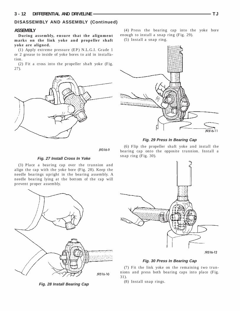
SSEMBLYDuring assembly, ensure that the alignmentarks on the link yoke and propeller shaft
oke are aligned.(1) Apply extreme pressure (EP) N.L.G.I. Grade 1
r 2 grease to inside of yoke bores to aid in installa-ion.
(2) Fit a cross into the propeller shaft yoke (Fig.7).
(3) Place a bearing cap over the trunnion andlign the cap with the yoke bore (Fig. 28). Keep theeedle bearings upright in the bearing assembly. Aeedle bearing lying at the bottom of the cap willrevent proper assembly.
Fig. 27 Install Cross In Yoke
Fig. 28 Install Bearing Cap
(4) Press the bearing cap into the yoke boreenough to install a snap ring (Fig. 29).
(5) Install a snap ring.
(6) Flip the propeller shaft yoke and install thebearing cap onto the opposite trunnion. Install asnap ring (Fig. 30).
(7) Fit the link yoke on the remaining two trun-nions and press both bearing caps into place (Fig.31).
(8) Install snap rings.
Fig. 29 Press In Bearing Cap
Fig. 30 Press In Bearing Cap
lt
otc
p
t
bd
TJ DIFFERENTIAL AND DRIVELINE 3 - 13
DISASSEMBLY AND ASSEMBLY (Continued)
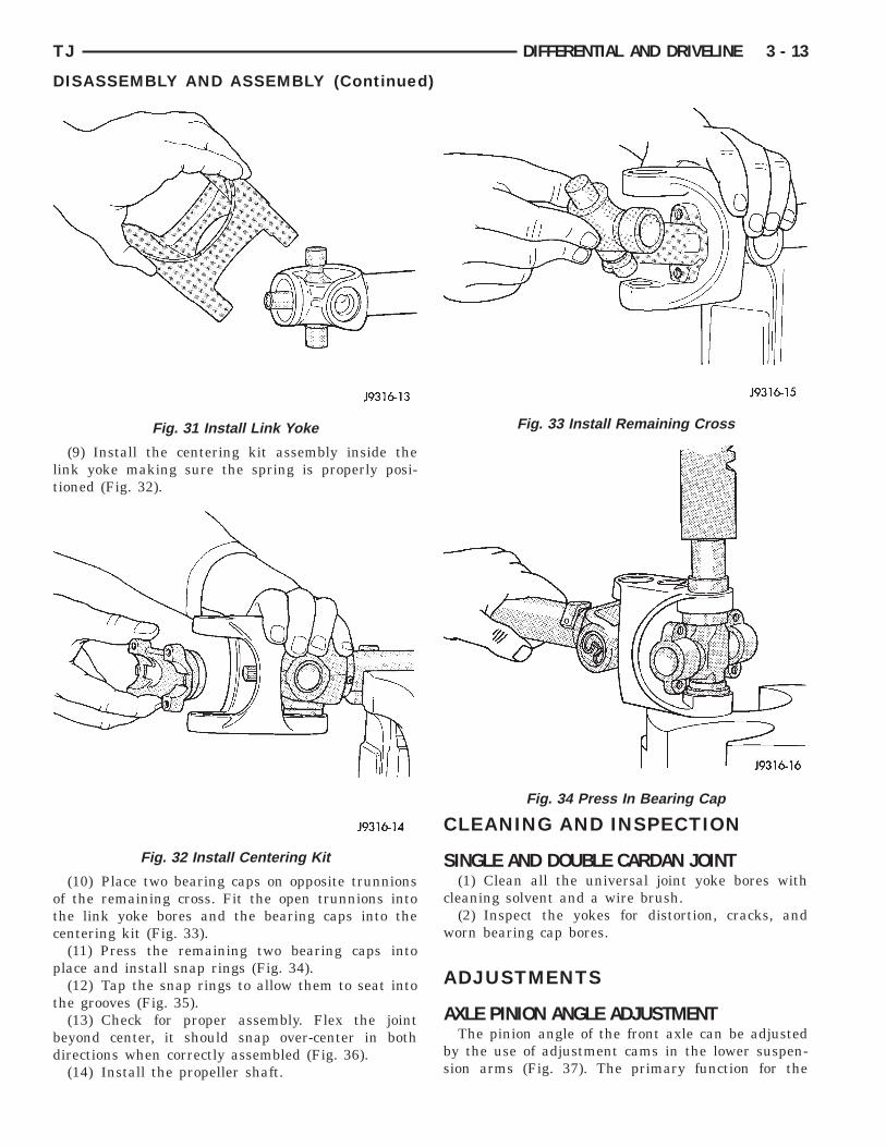
(9) Install the centering kit assembly inside theink yoke making sure the spring is properly posi-ioned (Fig. 32).
(10) Place two bearing caps on opposite trunnionsf the remaining cross. Fit the open trunnions intohe link yoke bores and the bearing caps into theentering kit (Fig. 33).(11) Press the remaining two bearing caps into
lace and install snap rings (Fig. 34).(12) Tap the snap rings to allow them to seat into
he grooves (Fig. 35).(13) Check for proper assembly. Flex the joint
eyond center, it should snap over-center in bothirections when correctly assembled (Fig. 36).(14) Install the propeller shaft.
Fig. 31 Install Link Yoke
Fig. 32 Install Centering Kit
CLEANING AND INSPECTION
SINGLE AND DOUBLE CARDAN JOINT(1) Clean all the universal joint yoke bores with
cleaning solvent and a wire brush.(2) Inspect the yokes for distortion, cracks, and
worn bearing cap bores.
ADJUSTMENTS
AXLE PINION ANGLE ADJUSTMENTThe pinion angle of the front axle can be adjusted
by the use of adjustment cams in the lower suspen-sion arms (Fig. 37). The primary function for the
Fig. 33 Install Remaining Cross
Fig. 34 Press In Bearing Cap

coaatewif
a
3 - 14 DIFFERENTIAL AND DRIVELINE TJ
ADJUSTMENTS (Continued)
ams is to adjust the caster angle for the alignmentf the front suspension. When using the cams todjust the pinion angle, make sure that both camsre moved equally. After the pinion angle is adjusted,he front suspension alignment should be checked tonsure that side-to-side caster angles variance isith-in the acceptable range. Having the correct pin-
on angle does have priority over having the pre-erred caster angle.
A cam kit is available to be installed in the rearxle lower suspension arms in order to provide
Fig. 35 Seat Snap Rings In Groove
Fig. 36 Check Assembly
adjustablity of the pinion angle. Follow the proce-dures supplied with the kit in order to ensure a safeinstallation.
SPECIFICATIONS
TORQUE
DESCRIPTION TORQUEFront Propeller ShaftBolts, Rear Yoke . . . . . . . . . . . . . 27 N·m (20 ft. lbs.)Bolts, Front Yoke . . . . . . . . . . . . 41 N·m (30 ft. lbs.)Rear Propeller ShaftBolts, Rear Yoke . . . . . . . . . . . . . 19 N·m (14 ft. lbs.)
SPECIAL TOOLS
PROPELLER SHAFT
Fig. 37 Adjustment Cam
Inclinometer—7663

G
D
D
S
R
G
1
ssp
to
ri
sbhsy
sbow
TJ DIFFERENTIAL AND DRIVELINE 3 - 15
181 FBI AXLE
INDEX
page page
D
C
A
S
S
ENERAL INFORMATION181 FBI AXLE . . . . . . . . . . . . . . . . . . . . . . . . . . . 15LUBRICANT SPECIFICATIONS . . . . . . . . . . . . . . 15ESCRIPTION AND OPERATIONSTANDARD DIFFERENTIAL . . . . . . . . . . . . . . . . 16IAGNOSIS AND TESTINGBEARING NOISE . . . . . . . . . . . . . . . . . . . . . . . . 17DRIVELINE SNAP . . . . . . . . . . . . . . . . . . . . . . . 17FRONT AXLES . . . . . . . . . . . . . . . . . . . . . . . . . . 18GEAR NOISE . . . . . . . . . . . . . . . . . . . . . . . . . . . 16GENERAL INFORMATION . . . . . . . . . . . . . . . . . 16LOW SPEED KNOCK . . . . . . . . . . . . . . . . . . . . . 17VIBRATION . . . . . . . . . . . . . . . . . . . . . . . . . . . . 17ERVICE PROCEDURESLUBRICANT CHANGE . . . . . . . . . . . . . . . . . . . . 20EMOVAL AND INSTALLATIONAXLE BUSHING REPLACEMENT . . . . . . . . . . . . 27AXLE SHAFT OIL SEAL . . . . . . . . . . . . . . . . . . . 31AXLE SHAFT—CARDAN U-JOINT . . . . . . . . . . . 21COLLAPSIBLE SPACER . . . . . . . . . . . . . . . . . . . 23DIFFERENTIAL . . . . . . . . . . . . . . . . . . . . . . . . . 27DIFFERENTIAL SIDE BEARINGS . . . . . . . . . . . . 30
DRIVE AXLE ASSEMBLY . . . . . . . . . . . . . . . . . . 20HUB BEARING AND AXLE SHAFT . . . . . . . . . . . 25PINION GEAR . . . . . . . . . . . . . . . . . . . . . . . . . . 32PINION SHAFT SEAL . . . . . . . . . . . . . . . . . . . . . 22RING GEAR . . . . . . . . . . . . . . . . . . . . . . . . . . . . 31STEERING KNUCKLE AND BALL STUDS . . . . . . 27ISASSEMBLY AND ASSEMBLYFINAL ASSEMBLY . . . . . . . . . . . . . . . . . . . . . . . 36STANDARD DIFFERENTIAL . . . . . . . . . . . . . . . 36LEANING AND INSPECTIONAXLE COMPONENTS . . . . . . . . . . . . . . . . . . . . . 37CARDAN U-JOINT . . . . . . . . . . . . . . . . . . . . . . . 37DJUSTMENTSDIFFERENTIAL BEARING PRELOAD AND
GEAR BACKLASH . . . . . . . . . . . . . . . . . . . . . . 38GEAR CONTACT PATTERN ANALYSIS . . . . . . . . 43PINION GEAR DEPTH . . . . . . . . . . . . . . . . . . . . 37PECIFICATIONS181 FBI AXLE . . . . . . . . . . . . . . . . . . . . . . . . . . . 45181 FBI AXLE . . . . . . . . . . . . . . . . . . . . . . . . . . . 45PECIAL TOOLS181 FBI AXLE . . . . . . . . . . . . . . . . . . . . . . . . . . . 45
ENERAL INFORMATION
81 FBI AXLEThe 181 Front Beam-design Iron (FBI) axle con-
ists of a cast iron differential housing with axlehaft tubes extending from either side. The tubes areressed into the differential housing and welded.The integral type housing, hypoid gear design has
he centerline of the pinion set below the centerlinef the ring gear.The axle has a fitting for a vent hose used to
elieve internal pressure caused by lubricant vapor-zation and internal expansion.
The axles are equipped with semi–floating axlehafts, meaning that loads are supported by the hubearings. The axle shafts are retained by nuts at theub bearings. The hub bearings are bolted to theteering knuckle at the outboard end of the axle tubeoke. The hub bearings are serviced as an assembly.For vehicles with ABS brakes, the ABS wheel
peed sensors are attached to the knuckle assem-lies. The tone rings for the ABS system are pressednto the axle shaft. Do not damage ABS toneheel or the sensor when removing axle shafts.
The stamped steel cover provides a means forinspection and servicing the differential.
The 181 FBI axle has the assembly part numberand gear ratio listed on a tag. The tag is attached tothe housing cover by a cover bolt. Build date identi-fication codes are stamped on the cover side of theaxle shaft tube.
The differential case is a one–piece design. The dif-ferential pinion mate shaft is retained with a rollpin. Differential bearing preload and ring gear back-lash is adjusted by the use of shims (select thick-ness). The shims are located between the differentialbearing cones and case. Pinion bearing preload is setand maintained by the use of a collapsible spacer.
LUBRICANT SPECIFICATIONSA multi–purpose, hypoid gear lubricant which con-
forms to the following specifications should be used.Mopart Hypoid Gear Lubricant conforms to all ofthese specifications.
• The lubricant should have MIL–L–2105C andAPI GL 5 quality specifications.
• Lubricant is a thermally stable SAE 80W–90gear lubricant.
tl
p
Cmp
D
S
br
smpa
r
p
t
iodgp
t
F
3 - 16 DIFFERENTIAL AND DRIVELINE TJ
GENERAL INFORMATION (Continued)
• Lubricant for axles intended for heavy-duty orrailer tow use is SAE 75W–140 SYNTHETIC gearubricant.
The 181 FBI axle lubricant capacity is 1.2 L (2.5ts.).
AUTION: If axle is submerged in water, lubricantust be replaced immediately to avoid possibleremature axle failure.
ESCRIPTION AND OPERATION
TANDARD DIFFERENTIALThe differential gear system divides the torque
etween the axle shafts. It allows the axle shafts tootate at different speeds when turning corners.Each differential side gear is splined to an axle
haft. The pinion gears are mounted on a pinionate shaft and are free to rotate on the shaft. The
inion gear is fitted in a bore in the differential casend is positioned at a right angle to the axle shafts.In operation, power flow occurs as follows:• The pinion gear rotates the ring gear• The ring gear (bolted to the differential case)
otates the case• The differential pinion gears (mounted on the
inion mate shaft in the case) rotate the side gears• The side gears (splined to the axle shafts) rotate
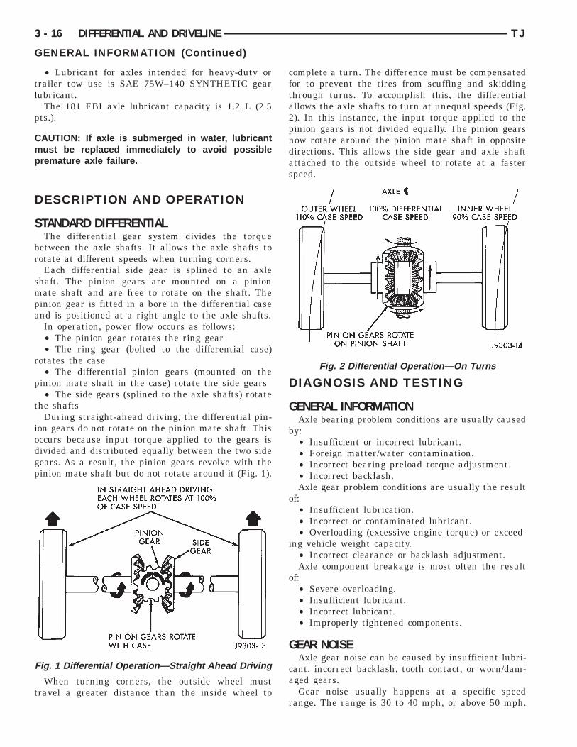
he shaftsDuring straight-ahead driving, the differential pin-
on gears do not rotate on the pinion mate shaft. Thisccurs because input torque applied to the gears isivided and distributed equally between the two sideears. As a result, the pinion gears revolve with theinion mate shaft but do not rotate around it (Fig. 1).
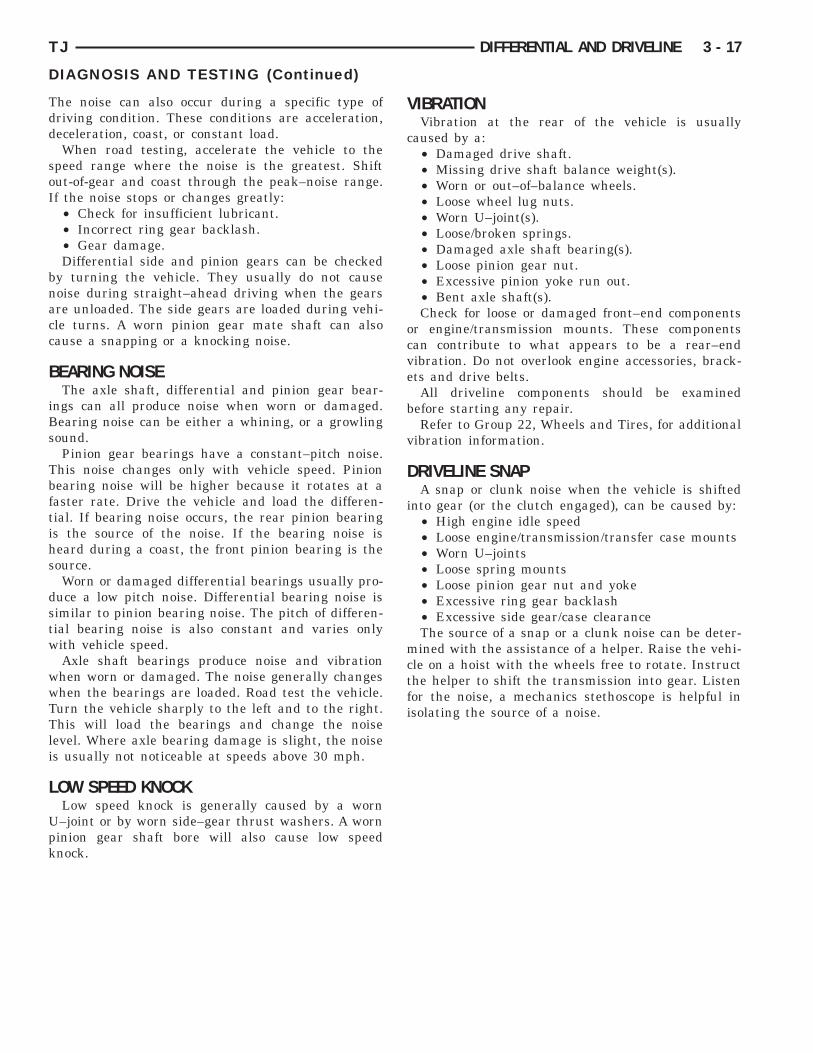
When turning corners, the outside wheel mustravel a greater distance than the inside wheel to
ig. 1 Differential Operation—Straight Ahead Driving
complete a turn. The difference must be compensatedfor to prevent the tires from scuffing and skiddingthrough turns. To accomplish this, the differentialallows the axle shafts to turn at unequal speeds (Fig.2). In this instance, the input torque applied to thepinion gears is not divided equally. The pinion gearsnow rotate around the pinion mate shaft in oppositedirections. This allows the side gear and axle shaftattached to the outside wheel to rotate at a fasterspeed.
DIAGNOSIS AND TESTING
GENERAL INFORMATIONAxle bearing problem conditions are usually caused
by:• Insufficient or incorrect lubricant.• Foreign matter/water contamination.• Incorrect bearing preload torque adjustment.• Incorrect backlash.Axle gear problem conditions are usually the result
of:• Insufficient lubrication.• Incorrect or contaminated lubricant.• Overloading (excessive engine torque) or exceed-
ing vehicle weight capacity.• Incorrect clearance or backlash adjustment.Axle component breakage is most often the result
of:• Severe overloading.• Insufficient lubricant.• Incorrect lubricant.• Improperly tightened components.
GEAR NOISEAxle gear noise can be caused by insufficient lubri-
cant, incorrect backlash, tooth contact, or worn/dam-aged gears.
Gear noise usually happens at a specific speedrange. The range is 30 to 40 mph, or above 50 mph.
Fig. 2 Differential Operation—On Turns
Tdd
soI
bnacc
B
iBs
Tbftihs
dstw
wwTTli
L
Upk
TJ DIFFERENTIAL AND DRIVELINE 3 - 17
DIAGNOSIS AND TESTING (Continued)
he noise can also occur during a specific type ofriving condition. These conditions are acceleration,eceleration, coast, or constant load.When road testing, accelerate the vehicle to the
peed range where the noise is the greatest. Shiftut-of-gear and coast through the peak–noise range.f the noise stops or changes greatly:• Check for insufficient lubricant.• Incorrect ring gear backlash.• Gear damage.Differential side and pinion gears can be checked
y turning the vehicle. They usually do not causeoise during straight–ahead driving when the gearsre unloaded. The side gears are loaded during vehi-le turns. A worn pinion gear mate shaft can alsoause a snapping or a knocking noise.
EARING NOISEThe axle shaft, differential and pinion gear bear-
ngs can all produce noise when worn or damaged.earing noise can be either a whining, or a growlingound.Pinion gear bearings have a constant–pitch noise.
his noise changes only with vehicle speed. Pinionearing noise will be higher because it rotates at aaster rate. Drive the vehicle and load the differen-ial. If bearing noise occurs, the rear pinion bearings the source of the noise. If the bearing noise iseard during a coast, the front pinion bearing is theource.Worn or damaged differential bearings usually pro-
uce a low pitch noise. Differential bearing noise isimilar to pinion bearing noise. The pitch of differen-ial bearing noise is also constant and varies onlyith vehicle speed.Axle shaft bearings produce noise and vibrationhen worn or damaged. The noise generally changeshen the bearings are loaded. Road test the vehicle.urn the vehicle sharply to the left and to the right.his will load the bearings and change the noise
evel. Where axle bearing damage is slight, the noises usually not noticeable at speeds above 30 mph.
OW SPEED KNOCKLow speed knock is generally caused by a worn–joint or by worn side–gear thrust washers. A worninion gear shaft bore will also cause low speednock.
VIBRATIONVibration at the rear of the vehicle is usually
caused by a:• Damaged drive shaft.• Missing drive shaft balance weight(s).• Worn or out–of–balance wheels.• Loose wheel lug nuts.• Worn U–joint(s).• Loose/broken springs.• Damaged axle shaft bearing(s).• Loose pinion gear nut.• Excessive pinion yoke run out.• Bent axle shaft(s).Check for loose or damaged front–end components
or engine/transmission mounts. These componentscan contribute to what appears to be a rear–endvibration. Do not overlook engine accessories, brack-ets and drive belts.
All driveline components should be examinedbefore starting any repair.
Refer to Group 22, Wheels and Tires, for additionalvibration information.
DRIVELINE SNAPA snap or clunk noise when the vehicle is shifted
into gear (or the clutch engaged), can be caused by:• High engine idle speed• Loose engine/transmission/transfer case mounts• Worn U–joints• Loose spring mounts• Loose pinion gear nut and yoke• Excessive ring gear backlash• Excessive side gear/case clearanceThe source of a snap or a clunk noise can be deter-
mined with the assistance of a helper. Raise the vehi-cle on a hoist with the wheels free to rotate. Instructthe helper to shift the transmission into gear. Listenfor the noise, a mechanics stethoscope is helpful inisolating the source of a noise.

F
3 - 18 DIFFERENTIAL AND DRIVELINE TJ
DIAGNOSIS AND TESTING (Continued)
RONT AXLESDIAGNOSIS

TJ DIFFERENTIAL AND DRIVELINE 3 - 19
DIAGNOSIS AND TESTING (Continued)
CONTINUED

S
L
d
d
ls
s
a
a
TN
Gpt
T
3 - 20 DIFFERENTIAL AND DRIVELINE TJ
ERVICE PROCEDURES
UBRICANT CHANGE(1) Raise and support the vehicle.(2) Remove the lubricant fill hole plug from the
ifferential housing cover.(3) Remove the differential housing cover and
rain the lubricant from the housing.(4) Clean the housing cavity with a flushing oil,
ight engine oil or lint free cloth. Do not use water,team, kerosene or gasoline for cleaning.(5) Remove the sealant from the housing and cover
urfaces. Use solvent to clean the mating surfaces.(6) Apply a bead of Mopart Silicone Rubber Seal-
nt, or equivalent, to the housing cover (Fig. 3).
Install the housing cover within 5 minutesfter applying the sealant.(7) Install the cover and any identification tag.
ighten the cover bolts in a criss–cross pattern to 41·m (30 ft. lbs.) torque.(8) Refill the differential with Mopart Hypoidear Lubricant, or equivalent, to bottom of the filllug hole. Refer to the Lubricant Specifications inhis group for the quantity necessary.
(9) Install the fill hole plug and lower the vehicle.ighten fill plug to 34 N·m (25 ft. lbs.).
Fig. 3 Typical Housing Cover With Sealant
REMOVAL AND INSTALLATION
DRIVE AXLE ASSEMBLY
REMOVAL(1) Raise and support the vehicle.(2) Position a suitable lifting device under the
axle.(3) Secure axle to device.(4) Remove the wheels and tires.(5) Remove the brake rotors and calipers from the
axle. Refer to Group 5, Brakes, for proper procedures.(6) Disconnect the wheel sensor wiring harness
from the vehicle wiring harness, if necessary.(7) Disconnect the vent hose from the axle shaft
tube.(8) Mark the propeller shaft and yoke for installa-
tion alignment reference.(9) Remove propeller shaft.(10) Disconnect stabilizer bar links at the axle.(11) Disconnect shock absorbers from axle brack-
ets.(12) Disconnect track bar.(13) Disconnect the tie rod and drag link from the
steering knuckle. Refer to Group 2, Suspension, forproper procedures.
(14) Disconnect the steering damper from the axlebracket.
(15) Disconnect the upper and lower suspensionarms from the axle brackets.
(16) Lower the lifting device enough to remove theaxle. The coil springs will drop with the axle.
(17) Remove the coil springs from the axle.
INSTALLATION
CAUTION: The weight of the vehicle must be sup-ported by the springs before suspension arms andtrack bar fasteners can be tightened. If the springsare not at their normal ride position, ride height andhandling could be affected.
(1) Install the springs and retainer clips. Tightenthe retainer bolts to 21 N·m (16 ft. lbs.) torque.
(2) Support the axle on a suitable lifting deviceand position axle under the vehicle.
(3) Raise the axle and align it with the springpads.
(4) Position the upper and lower suspension armsin the axle brackets. Loosely install bolts and nuts tohold suspension arms to the axle brackets.
(5) Connect the vent hose to the axle shaft tube.(6) Connect the track bar to the axle bracket.
Loosely install the bolt to hold the track bar to theaxle bracket.

b
bt
kp
bt
G
n
p
l
Lt
l
Na
t
A
ata
R
Cty
(
w
lsp
ss
TJ DIFFERENTIAL AND DRIVELINE 3 - 21
REMOVAL AND INSTALLATION (Continued)
(7) Install the shock absorbers and tighten theolts to 23 N·m (17 ft. lbs.) torque.(8) Install the stabilizer bar links to the axle
rackets. Tighten the nut to 95 N·m (70 ft. lbs.)orque.
(9) Install the drag link and tie rod to the steeringnuckles. Refer to Group 2, Suspension, for properrocedures.(10) Install the steering damper to the axle
racket and tighten the nut to 75 N·m (55 ft. lbs.)orque.
(11) Install the brake rotors and calipers. Refer toroup 5, Brakes, for the proper procedures.(12) Connect the wheel speed sensor wiring har-
ess to the vehicle wiring harness, if necessary.(13) Align the previously made marks on the pro-
eller shaft and the yoke.(14) Install the straps and bolts to hold the propel-
er shaft to the yoke.(15) Check and fill axle lubricant. Refer to the
ubricant Specifications in this group for the quan-ity necessary.
(16) Install the wheel and tire assemblies.(17) Remove the lifting device from the axle and
ower the vehicle.(18) Tighten the upper suspension arm nuts to 75·m (55 ft. lbs.) torque. Tighten the lower suspensionrm nuts to 115 N·m (85 ft. lbs.) torque.(19) Tighten the track bar bolt at the axle bracket
o 100 N·m (74 ft. lbs.) torque.(20) Check the front wheel alignment.
XLE SHAFT—CARDAN U-JOINTSingle cardan U–joint components are not service-
ble. If defective, they must be replaced as a unit. Ifhe bearings, seals, spider, or bearing caps are dam-ged or worn, replace the complete U–joint.
EMOVAL
AUTION: Clamp only the narrow forged portion ofhe yoke in the vise. Also, to avoid distorting theoke, do not over tighten the vise jaws.
(1) Remove axle shaft.(2) Remove the bearing cap retaining snap rings
Fig. 4).It can be helpful to saturate the bearing capsith penetrating oil prior to removal.(3) Locate a socket where the inside diameter is
arger in diameter than the bearing cap. Place theocket (receiver) against the yoke and around theerimeter of the bearing cap to be removed.(4) Locate a socket where the outside diameter is
maller in diameter than the bearing cap. Place theocket (driver) against the opposite bearing cap.
(5) Position the yoke with the sockets in a vise(Fig. 5).
(6) Compress the vise jaws to force the bearing capinto the larger socket (receiver).
(7) Release the vise jaws. Remove the sockets andbearing cap that was partially forced out of the yoke.
(8) Repeat the above procedure for the remainingbearing cap.
(9) Remove the remaining bearing cap, bearings,seals and spider from the propeller shaft yoke.
Fig. 4 Axle Shaft Outer U–Joint
Fig. 5 Yoke Bearing Cap Removal

I
ll
ab
cv
ir
P
R
G
i
rtl
r
r
m
3 - 22 DIFFERENTIAL AND DRIVELINE TJ
REMOVAL AND INSTALLATION (Continued)
NSTALLATION(1) Pack the bearing caps 1/3 full of wheel bearing
ubricant. Apply extreme pressure (EP), lithium–baseubricant to aid in installation.
(2) Position the spider in the yoke. Insert the sealsnd bearings. Tap the bearing caps into the yokeores far enough to hold the spider in position.(3) Place the socket (driver) against one bearing
ap. Position the yoke with the socket wrench in aise.(4) Compress the vise to force the bearing caps
nto the yoke. Force the caps enough to install theetaining clips.(5) Install the bearing cap retaining clips.(6) Install axle shaft.
INION SHAFT SEAL
EMOVAL(1) Raise and support the vehicle.(2) Remove wheel and tire assemblies.(3) Remove brake rotors and calipers. Refer toroup 5, Brakes, for proper procedures.(4) Mark the propeller shaft and pinion yoke for
nstallation reference.(5) Remove the propeller shaft from the yoke.(6) Rotate the pinion gear three or four times.(7) Measure the amount of torque necessary to
otate the pinion gear with a (in. lbs.) dial-typeorque wrench. Record the torque reading for instal-ation reference.
(8) Using Holder 6958 to hold the pinion yoke,emove the pinion nut and washer.(9) Use Remover C-452 and Wrench C-3281 to
emove the pinion yoke (Fig. 6).
(10) Use a suitable pry tool or a slide hammerounted screw to remove the pinion seal.
Fig. 6 Pinion Yoke Removal
INSTALLATION(1) Apply a light coating of gear lubricant on the
lip of pinion seal. Install seal with Installer C-3972-Aand Handle C-4171 (Fig. 7).
(2) Install yoke on the pinion gear with InstallerW-162–D, Cup 8109, and Holder 6958 (Fig. 8).
CAUTION: Do not exceed the minimum tighteningtorque when installing the pinion yoke retaining nutat this point. Damage to collapsible spacer or bear-ings may result.
(3) Install the pinion washer and a new nut on thepinion gear. Tighten the nut only enough toremove the shaft end play.
(4) Rotate the pinion shaft using a (in. lbs.) torquewrench. Rotating torque should be equal to the read-ing recorded during removal, plus an additional 0.56N·m (5 in. lbs.) (Fig. 9).
(5) If the rotating torque is low, use Holder 6958 tohold the pinion yoke (Fig. 10), and tighten the pinionshaft nut in 6.8 N·m (5 ft. lbs.) increments untilproper rotating torque is achieved.
Fig. 7 Pinion Seal Installation
Fig. 8 Pinion Yoke Installation

Crta
ps
TJ DIFFERENTIAL AND DRIVELINE 3 - 23
REMOVAL AND INSTALLATION (Continued)
AUTION: If the maximum tightening torque iseached prior to reaching the required rotatingorque, the collapsible spacer may have been dam-ged. Replace the collapsible spacer.
(6) Align the installation reference marks on theropeller shaft and yoke and install the propellerhaft.
Fig. 9 Check Pinion Rotation Torque
Fig. 10 Tightening Pinion Shaft Nut—Typical
(7) Check and fill the gear lubricant. Refer to theLubricant Specifications for gear lubricant require-ments.
(8) Install the brake rotors and calipers. Refer toGroup 5, Brakes, for proper procedures.
(9) Install wheel and tire assemblies.(10) Lower the vehicle.
COLLAPSIBLE SPACER
REMOVAL W/PINION INSTALLED(1) Raise and support the vehicle.(2) Remove wheel and tire assemblies.(3) Remove brake rotors and calipers. Refer to
Group 5, Brakes, for proper procedures.(4) Mark the propeller shaft and pinion yoke for
installation reference.(5) Remove the propeller shaft from the yoke.(6) Rotate the pinion gear three or four times.(7) Measure the amount of torque necessary to
rotate the pinion gear with a (in. lbs.) dial-typetorque wrench. Record the torque reading for instal-lation reference.
(8) Using Holder 6958 to hold the pinion yoke,remove the pinion nut and washer.
(9) Use Remover C-452 and Wrench C-3281 toremove the pinion yoke (Fig. 11).
(10) Use a suitable pry tool or a slide hammermounted screw, remove the pinion seal.
(11) Remove the front pinion bearing using a pairof suitable pick tools to pull the bearing straight offthe pinion gear shaft. It may be necessary to lightlytap the end of the pinion gear with a rawhide or rub-ber mallet if the bearing becomes bound on the pin-ion shaft.
(12) Remove the collapsible spacer.
Fig. 11 Pinion Yoke Removal
R
G
i
rtl
i
p
r
1f
I
i
i
la
3 - 24 DIFFERENTIAL AND DRIVELINE TJ
REMOVAL AND INSTALLATION (Continued)
EMOVAL W/PINION REMOVED(1) Raise and support the vehicle.(2) Remove wheel and tire assemblies.(3) Remove brake rotors and calipers. Refer toroup 5, Brakes, for proper procedures.(4) Mark the propeller shaft and pinion yoke for
nstallation reference.(5) Remove the propeller shaft from the yoke.(6) Rotate the pinion gear three or four times.(7) Measure the amount of torque necessary to
otate the pinion gear with a (in. lbs.) dial-typeorque wrench. Record the torque reading for instal-ation reference.
(8) Remove differential assembly from axle hous-ng.
(9) Using Holder 6958 to hold yoke, remove theinion nut and washer.(10) Using Remover C-452 and Wrench C-3281,
emove the pinion yoke from pinion shaft (Fig. 11).(11) Remove the pinion gear from housing (Fig.
2). Catch the pinion with your hand to prevent itrom falling and being damaged.
(12) Remove collapsible spacer from pinion shaft.
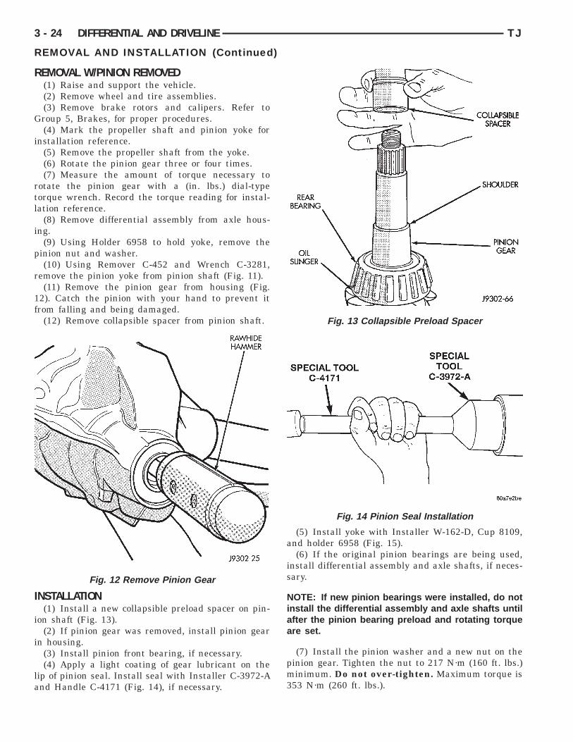
NSTALLATION(1) Install a new collapsible preload spacer on pin-
on shaft (Fig. 13).(2) If pinion gear was removed, install pinion gear
n housing.(3) Install pinion front bearing, if necessary.(4) Apply a light coating of gear lubricant on the
ip of pinion seal. Install seal with Installer C-3972-And Handle C-4171 (Fig. 14), if necessary.
Fig. 12 Remove Pinion Gear
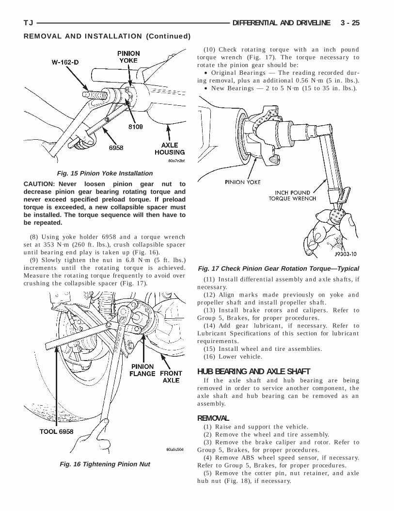
(5) Install yoke with Installer W-162-D, Cup 8109,and holder 6958 (Fig. 15).
(6) If the original pinion bearings are being used,install differential assembly and axle shafts, if neces-sary.
NOTE: If new pinion bearings were installed, do notinstall the differential assembly and axle shafts untilafter the pinion bearing preload and rotating torqueare set.
(7) Install the pinion washer and a new nut on thepinion gear. Tighten the nut to 217 N·m (160 ft. lbs.)minimum. Do not over-tighten. Maximum torque is353 N·m (260 ft. lbs.).
Fig. 13 Collapsible Preload Spacer
Fig. 14 Pinion Seal Installation
Cdntbb
su
iMc
TJ DIFFERENTIAL AND DRIVELINE 3 - 25
REMOVAL AND INSTALLATION (Continued)
AUTION: Never loosen pinion gear nut toecrease pinion gear bearing rotating torque andever exceed specified preload torque. If preload
orque is exceeded, a new collapsible spacer muste installed. The torque sequence will then have toe repeated.
(8) Using yoke holder 6958 and a torque wrenchet at 353 N·m (260 ft. lbs.), crush collapsible spacerntil bearing end play is taken up (Fig. 16).(9) Slowly tighten the nut in 6.8 N·m (5 ft. lbs.)
ncrements until the rotating torque is achieved.easure the rotating torque frequently to avoid over
rushing the collapsible spacer (Fig. 17).
Fig. 15 Pinion Yoke Installation
Fig. 16 Tightening Pinion Nut
(10) Check rotating torque with an inch poundtorque wrench (Fig. 17). The torque necessary torotate the pinion gear should be:
• Original Bearings — The reading recorded dur-ing removal, plus an additional 0.56 N·m (5 in. lbs.).
• New Bearings — 2 to 5 N·m (15 to 35 in. lbs.).
(11) Install differential assembly and axle shafts, ifnecessary.
(12) Align marks made previously on yoke andpropeller shaft and install propeller shaft.
(13) Install brake rotors and calipers. Refer toGroup 5, Brakes, for proper procedures.
(14) Add gear lubricant, if necessary. Refer toLubricant Specifications of this section for lubricantrequirements.
(15) Install wheel and tire assemblies.(16) Lower vehicle.
HUB BEARING AND AXLE SHAFTIf the axle shaft and hub bearing are being
removed in order to service another component, theaxle shaft and hub bearing can be removed as anassembly.
REMOVAL(1) Raise and support the vehicle.(2) Remove the wheel and tire assembly.(3) Remove the brake caliper and rotor. Refer to
Group 5, Brakes, for proper procedures.(4) Remove ABS wheel speed sensor, if necessary.
Refer to Group 5, Brakes, for proper procedures.(5) Remove the cotter pin, nut retainer, and axle
hub nut (Fig. 18), if necessary.
Fig. 17 Check Pinion Gear Rotation Torque—Typical
a
(t
b
I
aof
kle
3 - 26 DIFFERENTIAL AND DRIVELINE TJ
REMOVAL AND INSTALLATION (Continued)
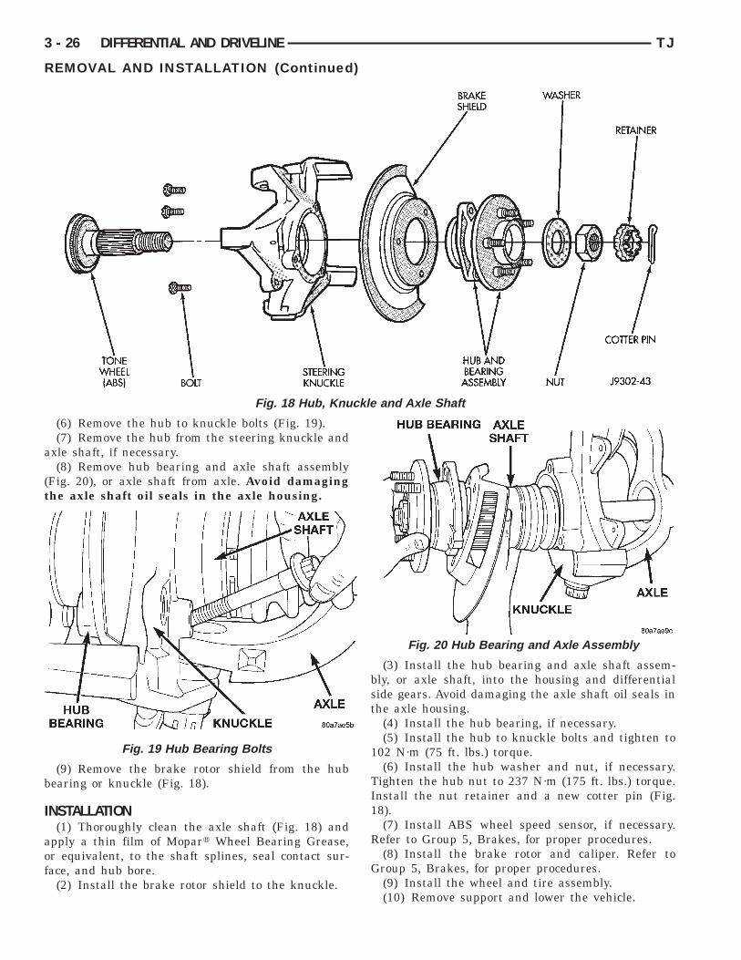
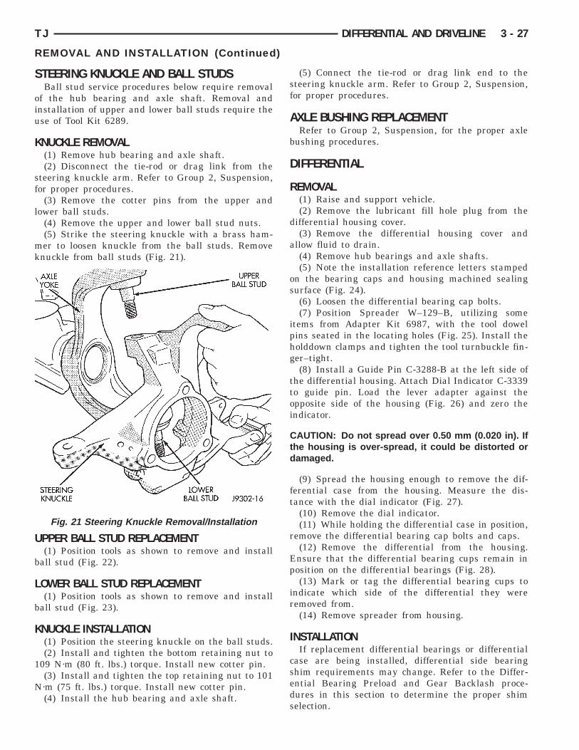
(6) Remove the hub to knuckle bolts (Fig. 19).(7) Remove the hub from the steering knuckle and
xle shaft, if necessary.(8) Remove hub bearing and axle shaft assembly
Fig. 20), or axle shaft from axle. Avoid damaginghe axle shaft oil seals in the axle housing.
(9) Remove the brake rotor shield from the hubearing or knuckle (Fig. 18).
NSTALLATION(1) Thoroughly clean the axle shaft (Fig. 18) and
pply a thin film of Mopart Wheel Bearing Grease,r equivalent, to the shaft splines, seal contact sur-ace, and hub bore.
(2) Install the brake rotor shield to the knuckle.
Fig. 18 Hub, Knuc
Fig. 19 Hub Bearing Bolts
(3) Install the hub bearing and axle shaft assem-bly, or axle shaft, into the housing and differentialside gears. Avoid damaging the axle shaft oil seals inthe axle housing.
(4) Install the hub bearing, if necessary.(5) Install the hub to knuckle bolts and tighten to
102 N·m (75 ft. lbs.) torque.(6) Install the hub washer and nut, if necessary.
Tighten the hub nut to 237 N·m (175 ft. lbs.) torque.Install the nut retainer and a new cotter pin (Fig.18).
(7) Install ABS wheel speed sensor, if necessary.Refer to Group 5, Brakes, for proper procedures.
(8) Install the brake rotor and caliper. Refer toGroup 5, Brakes, for proper procedures.
(9) Install the wheel and tire assembly.(10) Remove support and lower the vehicle.
and Axle Shaft
Fig. 20 Hub Bearing and Axle Assembly
S
oiu
K
sf
l
mk
U
b
L
b
K
1
N
TJ DIFFERENTIAL AND DRIVELINE 3 - 27
REMOVAL AND INSTALLATION (Continued)
TEERING KNUCKLE AND BALL STUDSBall stud service procedures below require removal
f the hub bearing and axle shaft. Removal andnstallation of upper and lower ball studs require these of Tool Kit 6289.
NUCKLE REMOVAL(1) Remove hub bearing and axle shaft.(2) Disconnect the tie-rod or drag link from the
teering knuckle arm. Refer to Group 2, Suspension,or proper procedures.
(3) Remove the cotter pins from the upper andower ball studs.
(4) Remove the upper and lower ball stud nuts.(5) Strike the steering knuckle with a brass ham-er to loosen knuckle from the ball studs. Remove
nuckle from ball studs (Fig. 21).
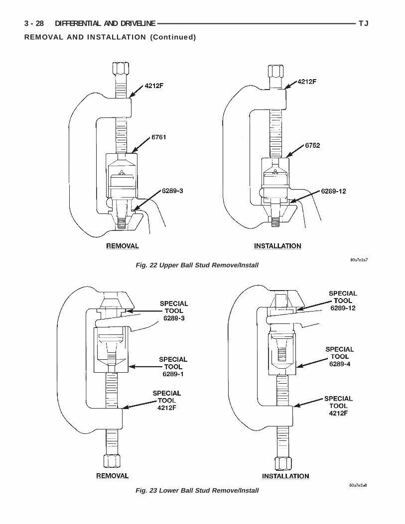
PPER BALL STUD REPLACEMENT(1) Position tools as shown to remove and install
all stud (Fig. 22).
OWER BALL STUD REPLACEMENT(1) Position tools as shown to remove and install
all stud (Fig. 23).
NUCKLE INSTALLATION(1) Position the steering knuckle on the ball studs.(2) Install and tighten the bottom retaining nut to
09 N·m (80 ft. lbs.) torque. Install new cotter pin.(3) Install and tighten the top retaining nut to 101·m (75 ft. lbs.) torque. Install new cotter pin.(4) Install the hub bearing and axle shaft.
Fig. 21 Steering Knuckle Removal/Installation
(5) Connect the tie-rod or drag link end to thesteering knuckle arm. Refer to Group 2, Suspension,for proper procedures.
AXLE BUSHING REPLACEMENTRefer to Group 2, Suspension, for the proper axle
bushing procedures.
DIFFERENTIAL
REMOVAL(1) Raise and support vehicle.(2) Remove the lubricant fill hole plug from the
differential housing cover.(3) Remove the differential housing cover and
allow fluid to drain.(4) Remove hub bearings and axle shafts.(5) Note the installation reference letters stamped
on the bearing caps and housing machined sealingsurface (Fig. 24).
(6) Loosen the differential bearing cap bolts.(7) Position Spreader W–129–B, utilizing some
items from Adapter Kit 6987, with the tool dowelpins seated in the locating holes (Fig. 25). Install theholddown clamps and tighten the tool turnbuckle fin-ger–tight.
(8) Install a Guide Pin C-3288-B at the left side ofthe differential housing. Attach Dial Indicator C-3339to guide pin. Load the lever adapter against theopposite side of the housing (Fig. 26) and zero theindicator.
CAUTION: Do not spread over 0.50 mm (0.020 in). Ifthe housing is over-spread, it could be distorted ordamaged.
(9) Spread the housing enough to remove the dif-ferential case from the housing. Measure the dis-tance with the dial indicator (Fig. 27).
(10) Remove the dial indicator.(11) While holding the differential case in position,
remove the differential bearing cap bolts and caps.(12) Remove the differential from the housing.
Ensure that the differential bearing cups remain inposition on the differential bearings (Fig. 28).
(13) Mark or tag the differential bearing cups toindicate which side of the differential they wereremoved from.
(14) Remove spreader from housing.
INSTALLATIONIf replacement differential bearings or differential
case are being installed, differential side bearingshim requirements may change. Refer to the Differ-ential Bearing Preload and Gear Backlash proce-dures in this section to determine the proper shimselection.
3 - 28 DIFFERENTIAL AND DRIVELINE TJ
REMOVAL AND INSTALLATION (Continued)
Fig. 22 Upper Ball Stud Remove/Install
Fig. 23 Lower Ball Stud Remove/Install

iphg
ttoi
Ctd
TJ DIFFERENTIAL AND DRIVELINE 3 - 29
REMOVAL AND INSTALLATION (Continued)
(1) Position Spreader W-129-B, utilizing sometems from Adapter Kit 6987, with the tool dowelins seated in the locating holes (Fig. 29). Install theolddown clamps and tighten the tool turnbuckle fin-er–tight.(2) Install a Guide Pin C-3288-B at the left side of
he differential housing. Attach Dial Indicator C-3339o guide pin. Load the lever adapter against thepposite side of the housing (Fig. 26) and zero thendicator.
AUTION: Do not spread over 0.50 mm (0.020 in). Ifhe housing is over-spread, it could be distorted oramaged.
Fig. 24 Bearing Cap Identification
Fig. 25 Install Axle Housing Spreader
(3) Spread the housing enough to install the casein the housing. Measure the distance with the dialindicator (Fig. 27).
(4) Remove the dial indicator.(5) Install differential case in the housing. Ensure
that the differential bearing cups remain in positionon the differential bearings. Tap the differential caseto ensure the bearings cups are fully seated in thehousing.
(6) Install the bearing caps at their original loca-tions (Fig. 30).
(7) Loosely install differential bearing cap bolts.(8) Remove axle housing spreader.(9) Tighten the bearing cap bolts to 61 N·m (45 ft.
lbs.) torque.(10) Install the hub bearings and axle shafts.
Fig. 26 Install Dial Indicator
Fig. 27 Spread Axle Housing

D
R
wB
I
eiDcs
3 - 30 DIFFERENTIAL AND DRIVELINE TJ
REMOVAL AND INSTALLATION (Continued)
IFFERENTIAL SIDE BEARINGS
EMOVAL(1) Remove differential case from axle housing.(2) Remove the bearings from the differential caseith Puller/Press C-293-PA, C-293-39 Adapterlocks, and Plug SP-3289 (Fig. 31).
NSTALLATIONIf replacement differential side bearings or differ-
ntial case are being installed, differential side bear-ng shim requirements may change. Refer to theifferential Bearing Preload and Gear Backlash pro-
edures in this section to determine the proper shimelection.
Fig. 28 Differential Case Removal
Fig. 29 Install Axle Housing Spreader
(1) Install differential side bearing shims onto dif-ferential case hubs.
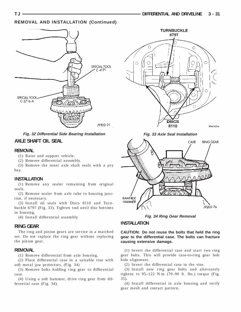
(2) Using Installer C-3716-A and Handle C-4171,install differential side bearings (Fig. 32).
(3) Install differential in axle housing.
Fig. 30 Differential Bearing Cap Reference Letters
Fig. 31 Differential Bearing Removal
A
R
b
I
s
t
bi
R
st
R
s
c
f
TJ DIFFERENTIAL AND DRIVELINE 3 - 31
REMOVAL AND INSTALLATION (Continued)
XLE SHAFT OIL SEAL
EMOVAL(1) Raise and support vehicle.(2) Remove differential assembly.(3) Remove the inner axle shaft seals with a pry
ay.
NSTALLATION(1) Remove any sealer remaining from original
eals.(2) Remove sealer from axle tube to housing junc-
ion, if necessary.(3) Install oil seals with Discs 8110 and Turn-
uckle 6797 (Fig. 33). Tighten tool until disc bottomsn housing.
(4) Install differential assembly.
ING GEARThe ring and pinion gears are service in a matched
et. Do not replace the ring gear without replacinghe pinion gear.
EMOVAL(1) Remove differential from axle housing.(2) Place differential case in a suitable vise with
oft metal jaw protectors. (Fig. 34)(3) Remove bolts holding ring gear to differential
ase.(4) Using a soft hammer, drive ring gear from dif-
erential case (Fig. 34).
Fig. 32 Differential Side Bearing Installation
INSTALLATION
CAUTION: Do not reuse the bolts that held the ringgear to the differential case. The bolts can fracturecausing extensive damage.
(1) Invert the differential case and start two ringgear bolts. This will provide case-to-ring gear bolthole alignment.
(2) Invert the differential case in the vise.(3) Install new ring gear bolts and alternately
tighten to 95–122 N·m (70–90 ft. lbs.) torque (Fig.35).
(4) Install differential in axle housing and verifygear mesh and contact pattern.
Fig. 33 Axle Seal Installation
Fig. 34 Ring Gear Removal

P
mr
R
i
i
U
t
r
3 - 32 DIFFERENTIAL AND DRIVELINE TJ
REMOVAL AND INSTALLATION (Continued)
INION GEARThe ring and pinion gears are serviced as aatched set. Do not replace the pinion gear without
eplacing the ring gear.
EMOVAL(1) Remove differential assembly from axle hous-
ng.(2) Mark pinion yoke and propeller shaft for
nstallation alignment.(3) Disconnect propeller shaft from pinion yoke.sing suitable wire, tie propeller shaft to underbody.(4) Using Holder 6958 to the hold yoke, remove
he pinion nut and washer (Fig. 36).(5) Using Remover C–452 and Holder C-3281,
emove the pinion yoke from pinion shaft (Fig. 37).
Fig. 35 Ring Gear Bolt Installation
Fig. 36 Pinion Yoke Holder—Typical
(6) Remove the pinion gear and collapsible spacerfrom housing (Fig. 38). Catch the pinion with yourhand to prevent it from falling and being damaged.
(7) Remove the front pinion bearing cup, bearing,oil slinger, if equipped, and pinion seal with RemoverC-4345 and Handle C–4171 (Fig. 39).
(8) Remove the rear pinion bearing cup from axlehousing (Fig. 40). Use Remover D-149 and HandleC–4171.
(9) Remove the depth shims from rear pinion bear-ing cup bore in axle housing. Record the thickness ofthe depth shims.
Fig. 37 Pinion Yoke Removal
Fig. 38 Remove Pinion Gear

NVc
p
iC
t
TJ DIFFERENTIAL AND DRIVELINE 3 - 33
REMOVAL AND INSTALLATION (Continued)
OTE: The pinion depth shims can be very thin.erify that all shims have been removed before pro-eeding.
(10) Remove the collapsible preload spacer frominion gear (Fig. 41).(11) Remove the rear pinion bearing from the pin-
on with Puller/Press C–293-PA and Adapters–293–39 (Fig. 42).Place 4 adapter blocks so they do not damage
he bearing cage.
Fig. 39 Front Bearing Cup Removal
Fig. 40 Rear Bearing Cup Removal
INSTALLATIONNOTE: Pinion depth shims are placed between therear pinion bearing cup and axle housing to achieveproper ring and pinion gear mesh. If the factoryinstalled ring and pinion gears are reused, the pin-ion depth shim should not require replacement.Refer to Pinion Gear Depth to select the properthickness shim before installing pinion gear.
Fig. 41 Collapsible Spacer
Fig. 42 Inner Bearing Removal

i
lcDr
lcH
e
3 - 34 DIFFERENTIAL AND DRIVELINE TJ
REMOVAL AND INSTALLATION (Continued)
(1) Place proper thickness depth shim in rear pin-on bearing cup bore in the axle housing.
(2) Apply Mopart Door Ease, or equivalent, stickubricant to outside surface of rear pinion bearingup. Install the bearing cup with Installer D-146 andriver Handle C–4171 (Fig. 43). Verify cup is cor-
ectly seated.
(3) Apply Mopart Door Ease, or equivalent, stickubricant to outside surface of front pinion bearingup. Install the bearing cup with Installer D-130 andandle C–4171 (Fig. 44).
(4) Install front pinion bearing, and oil slinger, ifquipped.
Fig. 43 Rear Pinion Bearing Cup Installation
Fig. 44 Pinion Outer Bearing Cup Installation
(5) Apply a light coating of gear lubricant on thelip of pinion seal. Install seal with Installer C-3972-Aand Handle C–4171 (Fig. 45).
(6) Install the rear pinion bearing and oil slinger,if equipped, on the pinion gear with Installer W-262and a shop press (Fig. 46).
(7) Install a new collapsible preload spacer on pin-ion shaft and install pinion gear in housing (Fig. 47).
(8) Install yoke with Installer W-162-B, Cup 8109,and Holder 6958 (Fig. 48).
(9) Install the pinion washer and a new nut on thepinion gear. Tighten the nut to 216 N·m (160 ft. lbs.)minimum. Do not over–tighten. Maximum torqueis 352 N·m (260 ft. lbs.).
Fig. 45 Pinion Seal Installation
Fig. 46 Rear Pinion Bearing Installation

Cdntbb
3b
iMc
TJ DIFFERENTIAL AND DRIVELINE 3 - 35
REMOVAL AND INSTALLATION (Continued)
AUTION: Never loosen pinion gear nut toecrease pinion gear bearing rotating torque andever exceed specified preload torque. If preload
orque is exceeded a new collapsible spacer muste installed. The torque sequence will then have toe repeated.
(10) Using Holder 6958 and torque wrench (set at52 N·m (260 ft. lbs.)), crush collapsible spacer untilearing end play is taken up (Fig. 49).(11) Slowly tighten the nut in 6.8 N·m (5 ft. lb.)
ncrements until the rotating torque is achieved.easure the rotating torque frequently to avoid over
rushing the collapsible spacer (Fig. 50).
Fig. 47 Collapsible Preload Spacer
Fig. 48 Pinion Yoke Installation
(12) Check bearing rotating torque with an inchpound torque wrench (Fig. 50). The torque necessaryto rotate the pinion gear should be:
• Original Bearings — 1 to 3 N·m (10 to 20 in.lbs.).
• New Bearings — 2 to 5 N·m (15 to 35 in. lbs.).
(13) Install differential assembly.
Fig. 49 Tightening Pinion Nut
Fig. 50 Check Pinion Gear Rotation Torque

D
S
D
re
d
p
w
A
w
e
r
s
h
F
a
3 - 36 DIFFERENTIAL AND DRIVELINE TJ
ISASSEMBLY AND ASSEMBLY
TANDARD DIFFERENTIAL
ISASSEMBLY(1) Remove the ring gear.(2) Using a suitable roll pin punch, drive out the
oll pin holding pinion gear mate shaft in the differ-ntial case (Fig. 51).
(3) Remove the pinion gear mate shaft from theifferential case and the pinion mate gears.(4) Rotate differential side gears and remove the
inion mate gears and thrust washers (Fig. 52).(5) Remove the differential side gears and thrustashers.
SSEMBLY(1) Install the differential side gears and thrustashers.(2) Install the pinion mate gears and thrust wash-
rs.(3) Install the pinion gear mate shaft. Align the
oll pin holes in shaft and the differential case.(4) Install the roll pin to hold the pinion mate
haft in the differential case (Fig. 53).(5) Install the ring gear.(6) Lubricate all differential components with
ypoid gear lubricant.
INAL ASSEMBLY(1) Scrape the residual sealant from the housing
nd cover mating surfaces. Clean the mating surfaces
Fig. 51 Mate Shaft Roll Pin Removal
with mineral spirits. Apply a bead of Mopart SiliconeRubber Sealant, or equivalent, on the housing cover(Fig. 54).
Install the housing cover within 5 minutesafter applying the sealant.
(2) Install the cover on the differential with theattaching bolts. Install the identification tag. Tightenthe cover bolts to 41 N·m (30 ft. lbs.) torque.
Fig. 52 Pinion Mate Gear Removal
Fig. 53 Mate Shaft Roll Pin Installation
Cl
ct
C
C
vf
b
n
A
at
wcr
ff
TJ DIFFERENTIAL AND DRIVELINE 3 - 37
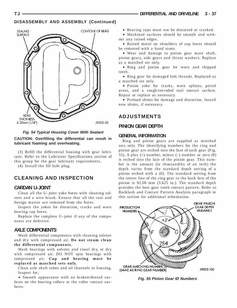
DISASSEMBLY AND ASSEMBLY (Continued)
AUTION: Overfilling the differential can result inubricant foaming and overheating.
(3) Refill the differential housing with gear lubri-ant. Refer to the Lubricant Specifications section ofhis group for the gear lubricant requirements.
(4) Install the fill hole plug.
LEANING AND INSPECTION
ARDAN U-JOINTClean all the U–joint yoke bores with cleaning sol-
ent and a wire brush. Ensure that all the rust andoreign matter are removed from the bores.
Inspect the yokes for distortion, cracks and wornearing cap bores.Replace the complete U–joint if any of the compo-
ents are defective.
XLE COMPONENTSWash differential components with cleaning solvent
nd dry with compressed air. Do not steam cleanhe differential components.
Wash bearings with solvent and towel dry, or dryith compressed air. DO NOT spin bearings with
ompressed air. Cup and bearing must beeplaced as matched sets only.Clean axle shaft tubes and oil channels in housing.Inspect for;• Smooth appearance with no broken/dented sur-
aces on the bearing rollers or the roller contact sur-aces.
Fig. 54 Typical Housing Cover With Sealant
• Bearing cups must not be distorted or cracked.• Machined surfaces should be smooth and with-
out any raised edges.• Raised metal on shoulders of cup bores should
be removed with a hand stone.• Wear and damage to pinion gear mate shaft,
pinion gears, side gears and thrust washers. Replaceas a matched set only.
• Ring and pinion gear for worn and chippedteeth.
• Ring gear for damaged bolt threads. Replaced asa matched set only.
• Pinion yoke for cracks, worn splines, pittedareas, and a rough/corroded seal contact surface.Repair or replace as necessary.
• Preload shims for damage and distortion. Installnew shims, if necessary.
ADJUSTMENTS
PINION GEAR DEPTH
GENERAL INFORMATIONRing and pinion gears are supplied as matched
sets only. The identifying numbers for the ring andpinion gear are etched into the face of each gear (Fig.55). A plus (+) number, minus (–) number or zero (0)is etched into the face of the pinion gear. This num-ber is the amount (in thousandths of an inch) thedepth varies from the standard depth setting of apinion etched with a (0). The standard setting fromthe center line of the ring gear to the back face of thepinion is 92.08 mm (3.625 in.). The standard depthprovides the best gear tooth contact pattern. Refer toBacklash and Contact Pattern Analysis paragraph inthis section for additional information.
Fig. 55 Pinion Gear ID Numbers

ab
vmtea
im
prdrite
P
awbS
B(
rp
3 - 38 DIFFERENTIAL AND DRIVELINE TJ
ADJUSTMENTS (Continued)
Compensation for pinion depth variance ischieved with select shims. The shims are placedehind the rear pinion bearing cup (Fig. 56).
If a new gear set is being installed, note the depthariance etched into both the original and replace-ent pinion gear. Add or subtract the thickness of
he original depth shims to compensate for the differ-nce in the depth variances. Refer to the Depth Vari-nce chart.Note where Old and New Pinion Marking columns
ntersect. Intersecting figure represents plus orinus the amount needed.Note the etched number on the face of the drive
inion gear (–1, –2, 0, +1, +2, etc.). The numbers rep-esent thousands of an inch deviation from the stan-ard. If the number is negative, add that value to theequired thickness of the depth shims. If the numbers positive, subtract that value from the thickness ofhe depth shim. If the number is 0 no change is nec-ssary.
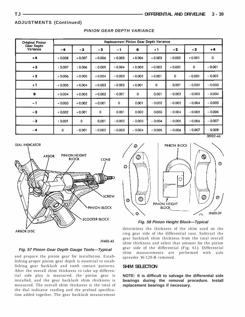
INION DEPTH MEASUREMENT AND ADJUSTMENTMeasurements are taken with pinion bearing cups
nd pinion bearings installed in the axle housingithout any shims placed behind the rear pinionearing cup. Take measurements with Pinion Gaugeet 6774 and Dial Indicator C-3339 (Fig. 57).(1) Assemble Pinion Height Block 6739, Pinionlock 6733, and rear pinion bearing onto Screw 6741
Fig. 57).(2) Insert assembled height gauge components,
ear bearing and screw into axle housing throughinion bearing cups (Fig. 58).
Fig. 56 Shim Locations
(3) Install front pinion bearing and Cone-nut 6740hand tight (Fig. 57).
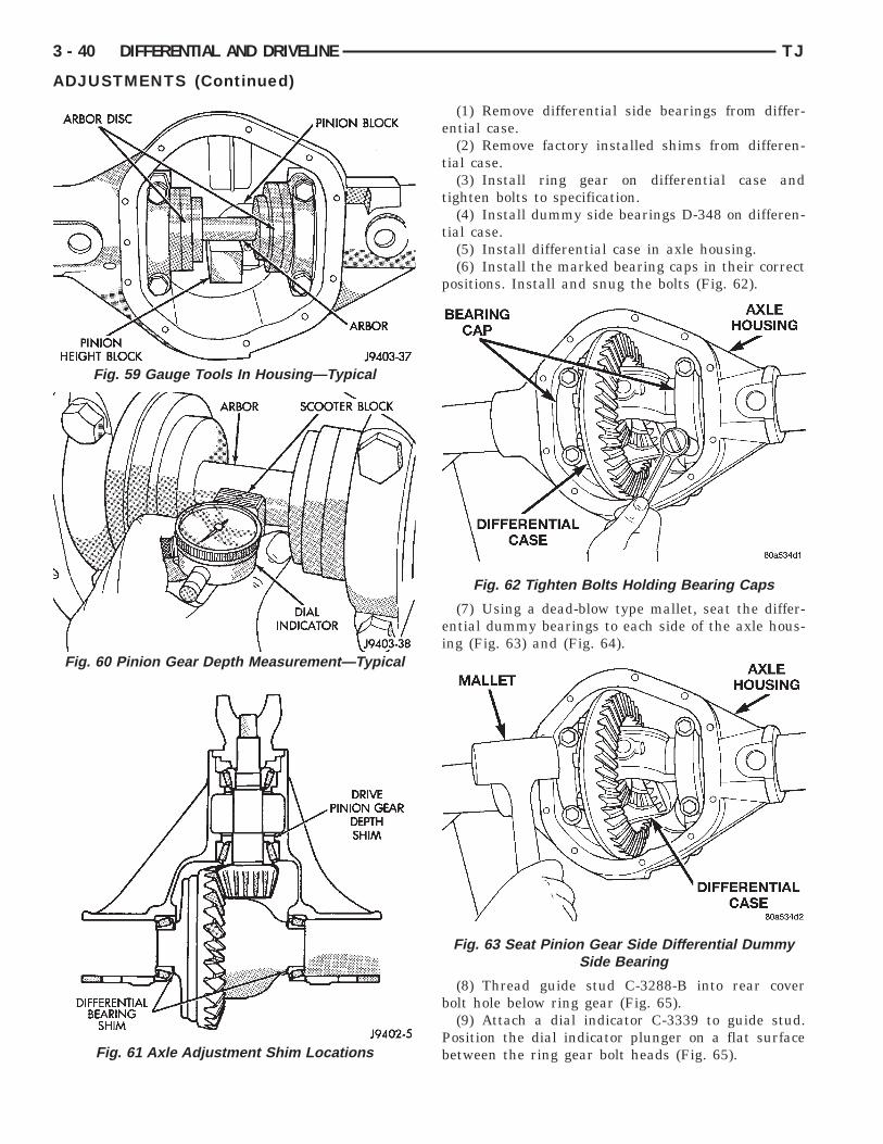
(4) Place Arbor Disc 6732 on Arbor D-115-3 in posi-tion in axle housing side bearing cradles (Fig. 59).Install differential bearing caps on Arbor Discs andtighten cap bolts to 41 N·m (30 ft. lbs.).
NOTE: Arbor Discs 6732 has different step diame-ters to fit other axles. Choose proper step for axlebeing serviced.
(5) Assemble Dial Indicator C-3339 into ScooterBlock D-115-2 and secure set screw.
(6) Place Scooter Block/Dial Indicator in positionin axle housing so dial probe and scooter block areflush against the rearward surface of the pinionheight block (Fig. 57). Hold scooter block in place andzero the dial indicator face to the pointer. Tightendial indicator face lock screw.
(7) With scooter block still in position against thepinion height block, slowly slide the dial indicatorprobe over the edge of the pinion height block.
(8) Slide the dial indicator probe across the gapbetween the pinion height block and the arbor barwith the scooter block against the pinion height block(Fig. 60). When the dial probe contacts the arbor bar,the dial pointer will turn clockwise. Bring dialpointer back to zero against the arbor bar, do notturn dial face. Continue moving the dial probe to thecrest of the arbor bar and record the highest reading.If the dial indicator can not achieve the zero reading,the rear bearing cup or the pinion depth gauge set isnot installed correctly.
(9) Select a shim equal to the dial indicator read-ing plus the drive pinion gear depth variance numberetched in the face of the pinion gear (Fig. 55). Forexample, if the depth variance is –2, add +0.002 in.to the dial indicator reading.
NOTE: If an oil slinger is used behind the inner pin-ion bearing, deduct the thickness of the slingerfrom the dial indicator reading and use that total forshim selection.
DIFFERENTIAL BEARING PRELOAD AND GEARBACKLASH
INTRODUCTIONDifferential side bearing preload and gear backlash
is achieved by selective shims positioned behind thedifferential side bearing cones. The proper shimthickness can be determined using slip-fit dummybearings D-348 in place of the differential side bear-ings and a dial indicator C-3339. Before proceedingwith the differential bearing preload and gear back-lash measurements, measure the pinion gear depth
allAtimtt
TJ DIFFERENTIAL AND DRIVELINE 3 - 39
ADJUSTMENTS (Continued)
nd prepare the pinion gear for installation. Estab-ishing proper pinion gear depth is essential to estab-ishing gear backlash and tooth contact patterns.fter the overall shim thickness to take up differen-
ial side play is measured, the pinion gear isnstalled, and the gear backlash shim thickness is
easured. The overall shim thickness is the total ofhe dial indicator reading and the preload specifica-ion added together. The gear backlash measurement
PINION GEAR D
Fig. 57 Pinion Gear Depth Gauge Tools—Typical
determines the thickness of the shim used on thering gear side of the differential case. Subtract thegear backlash shim thickness from the total overallshim thickness and select that amount for the piniongear side of the differential (Fig. 61). Differentialshim measurements are performed with axlespreader W-129-B removed.
SHIM SELECTION
NOTE: It is difficult to salvage the differential sidebearings during the removal procedure. Installreplacement bearings if necessary.
TH VARIANCE
Fig. 58 Pinion Height Block—Typical
EP
3 - 40 DIFFERENTIAL AND DRIVELINE TJ
ADJUSTMENTS (Continued)
(1) Remove differential side bearings from differ-ential case.
(2) Remove factory installed shims from differen-tial case.
(3) Install ring gear on differential case andtighten bolts to specification.
(4) Install dummy side bearings D-348 on differen-tial case.
(5) Install differential case in axle housing.(6) Install the marked bearing caps in their correct
positions. Install and snug the bolts (Fig. 62).
(7) Using a dead-blow type mallet, seat the differ-ential dummy bearings to each side of the axle hous-ing (Fig. 63) and (Fig. 64).
(8) Thread guide stud C-3288-B into rear coverbolt hole below ring gear (Fig. 65).
(9) Attach a dial indicator C-3339 to guide stud.Position the dial indicator plunger on a flat surfacebetween the ring gear bolt heads (Fig. 65).
Fig. 62 Tighten Bolts Holding Bearing Caps
Fig. 63 Seat Pinion Gear Side Differential DummySide Bearing
Fig. 59 Gauge Tools In Housing—Typical
Fig. 60 Pinion Gear Depth Measurement—Typical
Fig. 61 Axle Adjustment Shim Locations

s
s
tst
g
f
TJ DIFFERENTIAL AND DRIVELINE 3 - 41
ADJUSTMENTS (Continued)
(10) Push and hold differential case to pinion gearide of axle housing (Fig. 66).(11) Zero dial indicator face to pointer (Fig. 66).(12) Push and hold differential case to ring gear
ide of the axle housing (Fig. 67).(13) Record dial indicator reading (Fig. 67).(14) Add 0.008 in. (0.2 mm) to the zero end play
otal. This new total represents the thickness ofhims to compress, or preload the new bearings whenhe differential is installed.
(15) Rotate dial indicator out of the way on theuide stud.(16) Remove differential case and dummy bearings
rom axle housing.
Fig. 64 Seat Ring Gear Side Differential DummySide Bearing
Fig. 65 Differential Side play Measurement
(17) Install the pinion gear in axle housing. Installthe pinion yoke and establish the correct pinionrotating torque.
(18) Install differential case and dummy bearingsD-348 in axle housing (without shims), install bear-ing caps and tighten bolts snug.
(19) Seat ring gear side dummy bearing (Fig. 64).(20) Position the dial indicator plunger on a flat
surface between the ring gear bolt heads. (Fig. 65).(21) Push and hold differential case toward pinion
gear (Fig. 68).(22) Zero dial indicator face to pointer (Fig. 68).(23) Push and hold differential case to ring gear
side of the axle housing (Fig. 69).(24) Record dial indicator reading (Fig. 69).(25) Subtract 0.002 in. (0.05 mm) from the dial
indicator reading to compensate for backlash betweenring and pinion gears. This total is the thicknessshim required to achieve proper backlash.
Fig. 66 Hold Differential Case and Zero DialIndicator
Fig. 67 Hold Differential Case and Read DialIndicator

tta
s
f
h
c
fa
s
3 - 42 DIFFERENTIAL AND DRIVELINE TJ
ADJUSTMENTS (Continued)
(26) Subtract the backlash shim thickness fromhe total preload shim thickness. The remainder ishe shim thickness required on the pinion side of thexle housing.(27) Rotate dial indicator out of the way on guide
tud.(28) Remove differential case and dummy bearings
rom axle housing.(29) Install side bearing shims on differential case
ubs.(30) Install side bearings and cups on differential
ase.(31) Install spreader W-129-B, utilizing some items
rom Adapter Set 6987, on axle housing and spreadxle opening enough to receive differential case.(32) Install differential case in axle housing.(33) Remove spreader from axle housing.(34) Rotate the differential case several times to
eat the side bearings.
Fig. 68 Hold Differential Case and Zero DialIndicator
Fig. 69 Hold Differential Case and Read DialIndicator
(35) Position the indicator plunger against a ringgear tooth (Fig. 70).
(36) Push and hold ring gear upward while notallowing the pinion gear to rotate.
(37) Zero dial indicator face to pointer.(38) Push and hold ring gear downward while not
allowing the pinion gear to rotate. Dial indicatorreading should be between 0.12 mm (0.005 in.) and0.20 mm (0.008 in.). If backlash is not within specifi-cations transfer the necessary amount of shim thick-ness from one side of the axle housing to the other(Fig. 71).
(39) Verify differential case and ring gear runoutby measuring ring to pinion gear backlash at severallocations around the ring gear. Readings should notvary more than 0.05 mm (0.002 in.). If readings varymore than specified, the ring gear or the differentialcase is defective.
After the proper backlash is achieved, performGear Contact Pattern Analysis procedure.
Fig. 70 Ring Gear Backlash Measurement

G
wal
TJ DIFFERENTIAL AND DRIVELINE 3 - 43
ADJUSTMENTS (Continued)
EAR CONTACT PATTERN ANALYSIS
The ring and pinion gear teeth contact patternsill show if the pinion gear depth is correct in thexle housing. It will also show if the ring gear back-ash has been adjusted correctly. The backlash can be
Fig. 71 Backlash Shim Adjustment
adjusted within specifications to achieve desiredtooth contact patterns.
(1) Apply a thin coat of hydrated ferric oxide, orequivalent, to the drive and coast side of the ringgear teeth.
(2) Wrap, twist, and hold a shop towel around thepinion yoke to increase the turning resistance of thepinion gear. This will provide a more distinct contactpattern.
(3) Using a boxed end wrench on a ring gear bolt,Rotate the differential case one complete revolutionin both directions while a load is being applied fromshop towel.
The areas on the ring gear teeth with the greatestdegree of contact against the pinion gear teeth willsqueegee the compound to the areas with the leastamount of contact. Note and compare patterns on thering gear teeth to Gear Tooth Contact Patterns chart(Fig. 72) and adjust pinion depth and gear backlashas necessary.

3 - 44 DIFFERENTIAL AND DRIVELINE TJ
ADJUSTMENTS (Continued)
Fig. 72 Gear Tooth Contact Patterns

S
1
1
S
1
TJ DIFFERENTIAL AND DRIVELINE 3 - 45
PECIFICATIONS
81 FBI AXLE
Axle Type . . . . . . . . . . . . . . . . . . . . . . . . . . . HypoidLubricant . . . . . . . . SAE Thermally Stable 80W–90Lube Capacity . . . . . . . . . . . . . . . . . . 1.2 L (2.5 pts.)Axle Ratio . . . . . . . . . . . . . . . . 3.07, 3.55, 3.73, 4.10Differential Side Gear Clearance . . . . 0.12–0.20 mm
(0.005–0.008 in.)Ring Gear Diameter . . . . . . . . . 18.09 cm (7.125 in.)Backlash . . . . . . . . . . . 0–0.15 mm (0.005–0.008 in.)Pinion Std. Depth . . . . . . . . . . . 92.1 mm (3.625 in.)Pinion Bearing Rotating Torque . . . . . . . . . . . . . . .Original Bearings . . . . . . . . 1–2 N·m (10–20 in. lbs.)New Bearings . . . . . . . . . 1.5–4 N·m (15–35 in. lbs.)
81 FBI AXLE
DESCRIPTION TORQUEFill Hole Plug . . . . . . . . . . . . . . . 34 N·m (25 ft. lbs.)Diff. Cover Bolt . . . . . . . . . . . . . 41 N·m (30 ft. lbs.)Bearing Cap Bolt . . . . . . . . . . . . 61 N·m (45 ft. lbs.)Ring Gear Bolt . . . . . . . 95–122 N·m (70–90 ft. lbs.)Axle Nut . . . . . . . . . . . . . . . . . 237 N·m (175 ft. lbs.)Hub Brg. Bolt . . . . . . . . . . . . . . 102 N·m (75 ft. lbs.)Lower Ball Stud . . . . . . . . . . . . 108 N·m (80 ft. lbs.)Upper Ball Stud . . . . . . . . . . . . 101 N·m (75 ft. lbs.)
PECIAL TOOLS
81 FBI AXLE
Puller—C-293-PA
Plug—SP-3289
Adapter—C-293-39
Puller—C-452
Wrench—C-3281

3 - 46 DIFFERENTIAL AND DRIVELINE TJ
SPECIAL TOOLS (Continued)
Dial Indicator—C-3339
Driver—C-3716-A
Handle—C-4171
Installer—D-146
Remover—D-149
Installer—W-162-D
Cup—8109
Remover/Installer—6289
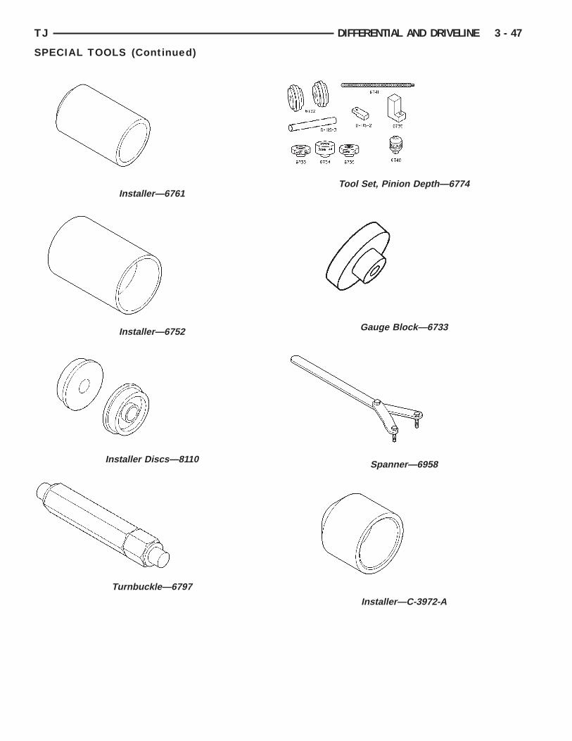
TJ DIFFERENTIAL AND DRIVELINE 3 - 47
SPECIAL TOOLS (Continued)
Installer—6761
Installer—6752
Installer Discs—8110
Turnbuckle—6797
Tool Set, Pinion Depth—6774
Gauge Block—6733
Spanner—6958
Installer—C-3972-A
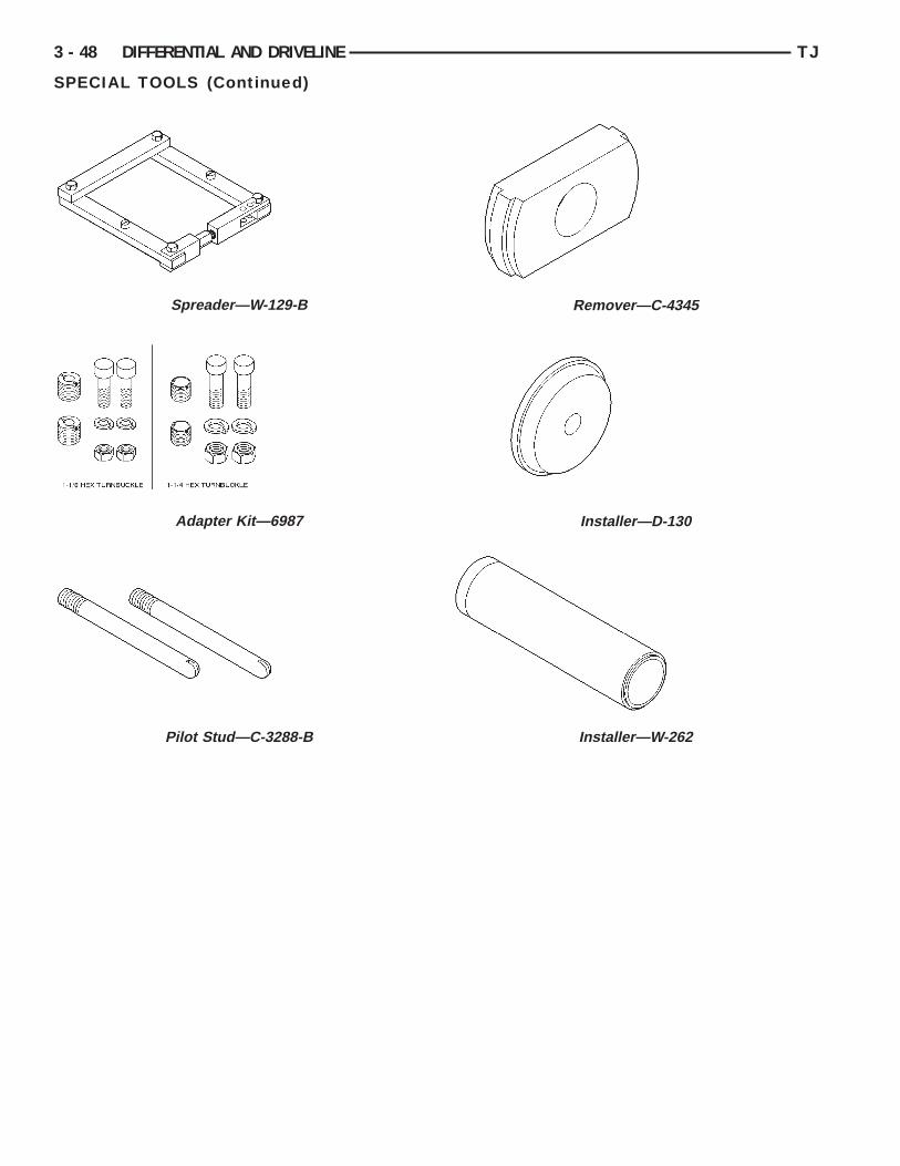
3 - 48 DIFFERENTIAL AND DRIVELINE TJ
SPECIAL TOOLS (Continued)
Spreader—W-129-B
Adapter Kit—6987
Pilot Stud—C-3288-B
Remover—C-4345
Installer—D-130
Installer—W-262

G
D
D
S
R
G
1
hath
to
se
ssC
e
hcta
TJ DIFFERENTIAL AND DRIVELINE 3 - 49
194 RBI AXLE
INDEX
page page
D
C
A
S
S
ENERAL INFORMATION194 RBI AXLE . . . . . . . . . . . . . . . . . . . . . . . . . . 49LUBRICANT SPECIFICATIONS . . . . . . . . . . . . . . 49ESCRIPTION AND OPERATIONSTANDARD DIFFERENTIAL . . . . . . . . . . . . . . . . 50TRAC-LOK OPERATION . . . . . . . . . . . . . . . . . . . 50IAGNOSIS AND TESTINGBEARING NOISE . . . . . . . . . . . . . . . . . . . . . . . . 51DRIVELINE SNAP . . . . . . . . . . . . . . . . . . . . . . . 52GEAR NOISE . . . . . . . . . . . . . . . . . . . . . . . . . . . 51GENERAL INFORMATION . . . . . . . . . . . . . . . . . 51LOW SPEED KNOCK . . . . . . . . . . . . . . . . . . . . . 52TRAC–LOK DIFFERENTIAL NOISE . . . . . . . . . . 52TRAC–LOK TEST . . . . . . . . . . . . . . . . . . . . . . . 52VIBRATION . . . . . . . . . . . . . . . . . . . . . . . . . . . . 52ERVICE PROCEDURESLUBRICANT CHANGE . . . . . . . . . . . . . . . . . . . . 55EMOVAL AND INSTALLATIONAXLE SHAFT . . . . . . . . . . . . . . . . . . . . . . . . . . . 59AXLE SHAFT SEAL AND BEARING . . . . . . . . . . 60COLLAPSIBLE SPACER . . . . . . . . . . . . . . . . . . . 57DIFFERENTIAL . . . . . . . . . . . . . . . . . . . . . . . . . 61
DIFFERENTIAL SIDE BEARINGS . . . . . . . . . . . . 63FINAL ASSEMBLY . . . . . . . . . . . . . . . . . . . . . . . 67PINION GEAR . . . . . . . . . . . . . . . . . . . . . . . . . . 64PINION SHAFT SEAL . . . . . . . . . . . . . . . . . . . . . 56REAR AXLE . . . . . . . . . . . . . . . . . . . . . . . . . . . . 55RING GEAR . . . . . . . . . . . . . . . . . . . . . . . . . . . . 63ISASSEMBLY AND ASSEMBLYSTANDARD DIFFERENTIAL . . . . . . . . . . . . . . . 68TRAC-LOK DIFFERENTIAL . . . . . . . . . . . . . . . . 69LEANING AND INSPECTIONAXLE COMPONENTS . . . . . . . . . . . . . . . . . . . . . 73TRAC-LOK . . . . . . . . . . . . . . . . . . . . . . . . . . . . . 73DJUSTMENTSDIFFERENTIAL BEARING PRELOAD AND
GEAR BACKLASH . . . . . . . . . . . . . . . . . . . . . . 75GEAR CONTACT PATTERN ANALYSIS . . . . . . . . 77PINION GEAR DEPTH . . . . . . . . . . . . . . . . . . . . 73PECIFICATIONS194 RBI AXLE . . . . . . . . . . . . . . . . . . . . . . . . . . 79194 RBI AXLE . . . . . . . . . . . . . . . . . . . . . . . . . . 79PECIAL TOOLS194 RBI AXLE . . . . . . . . . . . . . . . . . . . . . . . . . . 79
ENERAL INFORMATION
94 RBI AXLEThe 194 Rear Beam-design Iron (RBI) axle housing
as an iron center casting (differential housing) withxle shaft tubes extending from either side. Theubes are pressed into and welded to the differentialousing to form a one-piece axle housing.The integral type, hypoid gear design, housing has
he centerline of the pinion set below the centerlinef the ring gear.The axle has a vent hose to relieve internal pres-
ure caused by lubricant vaporization and internalxpansion.The axles are equipped with semi–floating axle
hafts, meaning that loads are supported by the axlehaft and bearings. The axle shafts are retained by–clips in the differential side gears.The cover provides a means for servicing the differ-
ntial without removing the axle.For vehicles equipped with ABS brakes, the axles
ave a tone ring pressed onto the axle shaft. Useare when removing axle shafts to ensure that theone wheel or the wheel speed sensor are not dam-ged.
The 194 RBI axle has the assembly part numberand gear ratio listed on a tag. The tag is attached tothe differential housing by a cover bolt. Build dateidentification codes are stamped on the cover side ofan axle shaft tube.
The differential case is a one-piece design. The dif-ferential pinion mate shaft is retained with athreaded pin. Differential bearing preload and ringgear backlash is adjusted by the use of selectivespacer shims. Pinion bearing preload is set andmaintained by the use of a collapsible spacer (Fig. 1).
LUBRICANT SPECIFICATIONSA multi-purpose, hypoid gear lubricant which con-
forms to the following specifications should be used.Mopart Hypoid Gear Lubricant conforms to all ofthese specifications.
• The lubricant should have MIL–L–2105C andAPI GL 5 quality specifications.
• Lubricant is a thermally stable SAE 80W–90gear lubricant.
• Lubricant for axles intended for heavy-duty ortrailer tow use is SAE 75W–140 SYNTHETIC gearlubricant.
Trac-lok differentials require the addition of 4 oz.of friction modifier to the axle lubricant. The 194 RBI
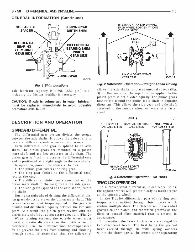
ai
Cmp
D
S
br
smpa
r
p
t
iodgp
tcft
3 - 50 DIFFERENTIAL AND DRIVELINE TJ
GENERAL INFORMATION (Continued)
xle lubricant capacity is 1.66L (3.50 pts.) total,ncluding the friction modifier if necessary.
AUTION: If axle is submerged in water, lubricantust be replaced immediately to avoid possibleremature axle failure.
ESCRIPTION AND OPERATION
TANDARD DIFFERENTIALThe differential gear system divides the torque
etween the axle shafts. It allows the axle shafts tootate at different speeds when turning corners.Each differential side gear is splined to an axle
haft. The pinion gears are mounted on a pinionate shaft and are free to rotate on the shaft. The
inion gear is fitted in a bore in the differential casend is positioned at a right angle to the axle shafts.In operation, power flow occurs as follows:• The pinion gear rotates the ring gear• The ring gear (bolted to the differential case)
otates the case• The differential pinion gears (mounted on the
inion mate shaft in the case) rotate the side gears• The side gears (splined to the axle shafts) rotate
he shaftsDuring straight-ahead driving, the differential pin-
on gears do not rotate on the pinion mate shaft. Thisccurs because input torque applied to the gears isivided and distributed equally between the two sideears. As a result, the pinion gears revolve with theinion mate shaft but do not rotate around it (Fig. 2).When turning corners, the outside wheel must
ravel a greater distance than the inside wheel toomplete a turn. The difference must be compensatedor to prevent the tires from scuffing and skiddinghrough turns. To accomplish this, the differential
Fig. 1 Shim Locations
allows the axle shafts to turn at unequal speeds (Fig.3). In this instance, the input torque applied to thepinion gears is not divided equally. The pinion gearsnow rotate around the pinion mate shaft in oppositedirections. This allows the side gear and axle shaftattached to the outside wheel to rotate at a fasterspeed.TRAC-LOK OPERATIONIn a conventional differential, if one wheel spins,
the opposite wheel will generate only as much torqueas the spinning wheel.
In the Trac-lok differential, part of the ring geartorque is transmitted through clutch packs whichcontain multiple discs. The clutches will have radialgrooves on the plates, and concentric grooves on thediscs or bonded fiber material that is smooth inappearance.
In operation, the Trac-lok clutches are engaged bytwo concurrent forces. The first being the preloadforce exerted through Belleville spring washerswithin the clutch packs. The second is the separating
Fig. 2 Differential Operation—Straight Ahead Driving
Fig. 3 Differential Operation—On Turns
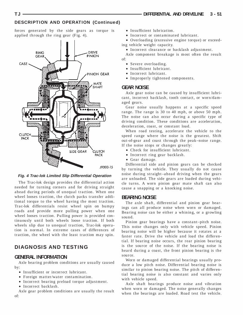
fa
nawtTrwtwtt
D
G
b
o
TJ DIFFERENTIAL AND DRIVELINE 3 - 51
DESCRIPTION AND OPERATION (Continued)
orces generated by the side gears as torque ispplied through the ring gear (Fig. 4).
The Trac-lok design provides the differential actioneeded for turning corners and for driving straighthead during periods of unequal traction. When oneheel looses traction, the clutch packs transfer addi-
ional torque to the wheel having the most traction.rac-lok differentials resist wheel spin on bumpyoads and provide more pulling power when oneheel looses traction. Pulling power is provided con-
inuously until both wheels loose traction. If bothheels slip due to unequal traction, Trac-lok opera-
ion is normal. In extreme cases of differences ofraction, the wheel with the least traction may spin.
IAGNOSIS AND TESTING
ENERAL INFORMATIONAxle bearing problem conditions are usually caused
y:• Insufficient or incorrect lubricant.• Foreign matter/water contamination.• Incorrect bearing preload torque adjustment.• Incorrect backlash.Axle gear problem conditions are usually the result
f:
Fig. 4 Trac-lok Limited Slip Differential Operation
• Insufficient lubrication.• Incorrect or contaminated lubricant.• Overloading (excessive engine torque) or exceed-
ing vehicle weight capacity.• Incorrect clearance or backlash adjustment.Axle component breakage is most often the result
of:• Severe overloading.• Insufficient lubricant.• Incorrect lubricant.• Improperly tightened components.
GEAR NOISEAxle gear noise can be caused by insufficient lubri-
cant, incorrect backlash, tooth contact, or worn/dam-aged gears.
Gear noise usually happens at a specific speedrange. The range is 30 to 40 mph, or above 50 mph.The noise can also occur during a specific type ofdriving condition. These conditions are acceleration,deceleration, coast, or constant load.
When road testing, accelerate the vehicle to thespeed range where the noise is the greatest. Shiftout-of-gear and coast through the peak–noise range.If the noise stops or changes greatly:
• Check for insufficient lubricant.• Incorrect ring gear backlash.• Gear damage.Differential side and pinion gears can be checked
by turning the vehicle. They usually do not causenoise during straight–ahead driving when the gearsare unloaded. The side gears are loaded during vehi-cle turns. A worn pinion gear mate shaft can alsocause a snapping or a knocking noise.
BEARING NOISEThe axle shaft, differential and pinion gear bear-
ings can all produce noise when worn or damaged.Bearing noise can be either a whining, or a growlingsound.
Pinion gear bearings have a constant–pitch noise.This noise changes only with vehicle speed. Pinionbearing noise will be higher because it rotates at afaster rate. Drive the vehicle and load the differen-tial. If bearing noise occurs, the rear pinion bearingis the source of the noise. If the bearing noise isheard during a coast, the front pinion bearing is thesource.
Worn or damaged differential bearings usually pro-duce a low pitch noise. Differential bearing noise issimilar to pinion bearing noise. The pitch of differen-tial bearing noise is also constant and varies onlywith vehicle speed.
Axle shaft bearings produce noise and vibrationwhen worn or damaged. The noise generally changeswhen the bearings are loaded. Road test the vehicle.
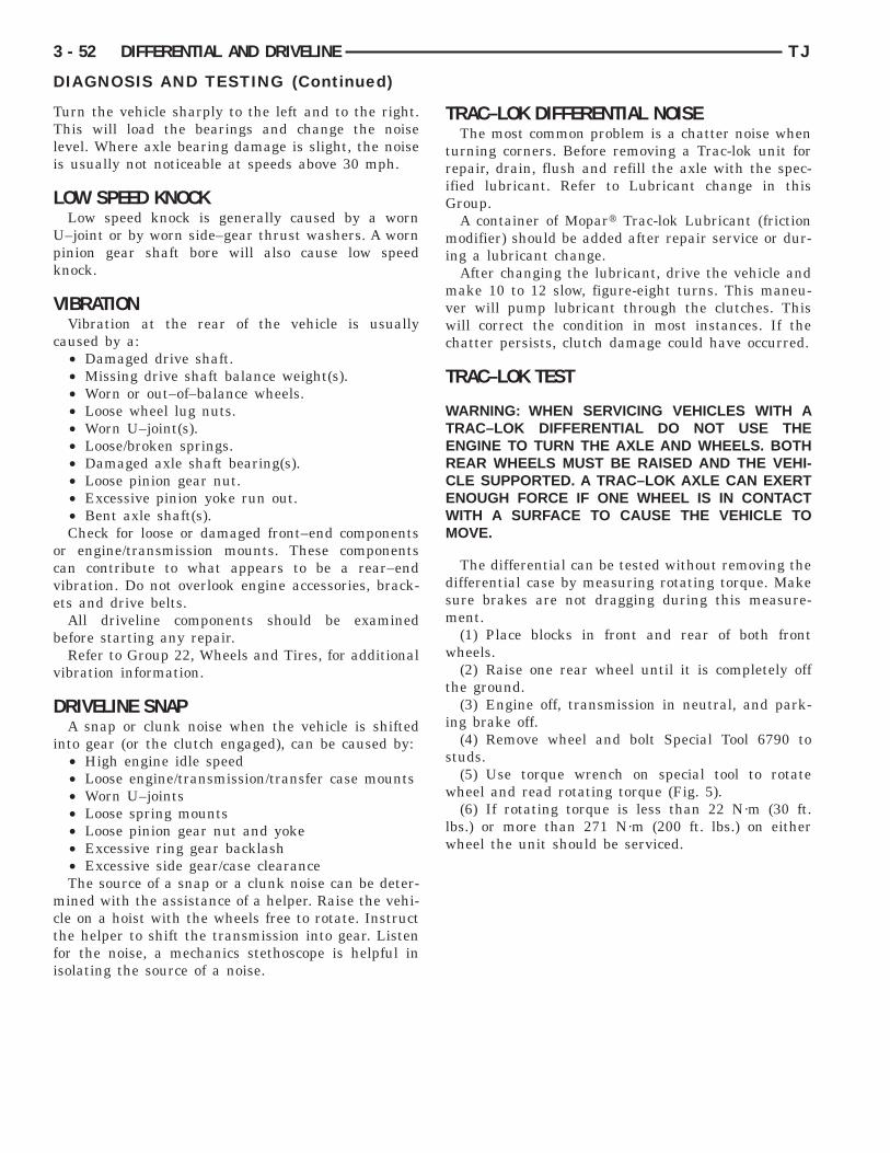
TTli
L
Upk
V
c
ocve
b
v
D
i
mctfi
mi
mvwc
3 - 52 DIFFERENTIAL AND DRIVELINE TJ
DIAGNOSIS AND TESTING (Continued)
urn the vehicle sharply to the left and to the right.his will load the bearings and change the noise
evel. Where axle bearing damage is slight, the noises usually not noticeable at speeds above 30 mph.
OW SPEED KNOCKLow speed knock is generally caused by a worn–joint or by worn side–gear thrust washers. A worninion gear shaft bore will also cause low speednock.
IBRATIONVibration at the rear of the vehicle is usually
aused by a:• Damaged drive shaft.• Missing drive shaft balance weight(s).• Worn or out–of–balance wheels.• Loose wheel lug nuts.• Worn U–joint(s).• Loose/broken springs.• Damaged axle shaft bearing(s).• Loose pinion gear nut.• Excessive pinion yoke run out.• Bent axle shaft(s).Check for loose or damaged front–end components
r engine/transmission mounts. These componentsan contribute to what appears to be a rear–endibration. Do not overlook engine accessories, brack-ts and drive belts.All driveline components should be examined
efore starting any repair.Refer to Group 22, Wheels and Tires, for additional
ibration information.
RIVELINE SNAPA snap or clunk noise when the vehicle is shifted
nto gear (or the clutch engaged), can be caused by:• High engine idle speed• Loose engine/transmission/transfer case mounts• Worn U–joints• Loose spring mounts• Loose pinion gear nut and yoke• Excessive ring gear backlash• Excessive side gear/case clearanceThe source of a snap or a clunk noise can be deter-ined with the assistance of a helper. Raise the vehi-
le on a hoist with the wheels free to rotate. Instructhe helper to shift the transmission into gear. Listenor the noise, a mechanics stethoscope is helpful insolating the source of a noise.
TRAC–LOK DIFFERENTIAL NOISEThe most common problem is a chatter noise when
turning corners. Before removing a Trac-lok unit forrepair, drain, flush and refill the axle with the spec-ified lubricant. Refer to Lubricant change in thisGroup.
A container of Mopart Trac-lok Lubricant (frictionodifier) should be added after repair service or dur-
ng a lubricant change.After changing the lubricant, drive the vehicle andake 10 to 12 slow, figure-eight turns. This maneu-
er will pump lubricant through the clutches. Thisill correct the condition in most instances. If the
hatter persists, clutch damage could have occurred.
TRAC–LOK TEST
WARNING: WHEN SERVICING VEHICLES WITH ATRAC–LOK DIFFERENTIAL DO NOT USE THEENGINE TO TURN THE AXLE AND WHEELS. BOTHREAR WHEELS MUST BE RAISED AND THE VEHI-CLE SUPPORTED. A TRAC–LOK AXLE CAN EXERTENOUGH FORCE IF ONE WHEEL IS IN CONTACTWITH A SURFACE TO CAUSE THE VEHICLE TOMOVE.
The differential can be tested without removing thedifferential case by measuring rotating torque. Makesure brakes are not dragging during this measure-ment.
(1) Place blocks in front and rear of both frontwheels.
(2) Raise one rear wheel until it is completely offthe ground.
(3) Engine off, transmission in neutral, and park-ing brake off.
(4) Remove wheel and bolt Special Tool 6790 tostuds.
(5) Use torque wrench on special tool to rotatewheel and read rotating torque (Fig. 5).
(6) If rotating torque is less than 22 N·m (30 ft.lbs.) or more than 271 N·m (200 ft. lbs.) on eitherwheel the unit should be serviced.

TJ DIFFERENTIAL AND DRIVELINE 3 - 53
DIAGNOSIS AND TESTING (Continued)
DIAGNOSIS CHART

3 - 54 DIFFERENTIAL AND DRIVELINE TJ
DIAGNOSIS AND TESTING (Continued)
DIAGNOSIS CHART — CONTINUED
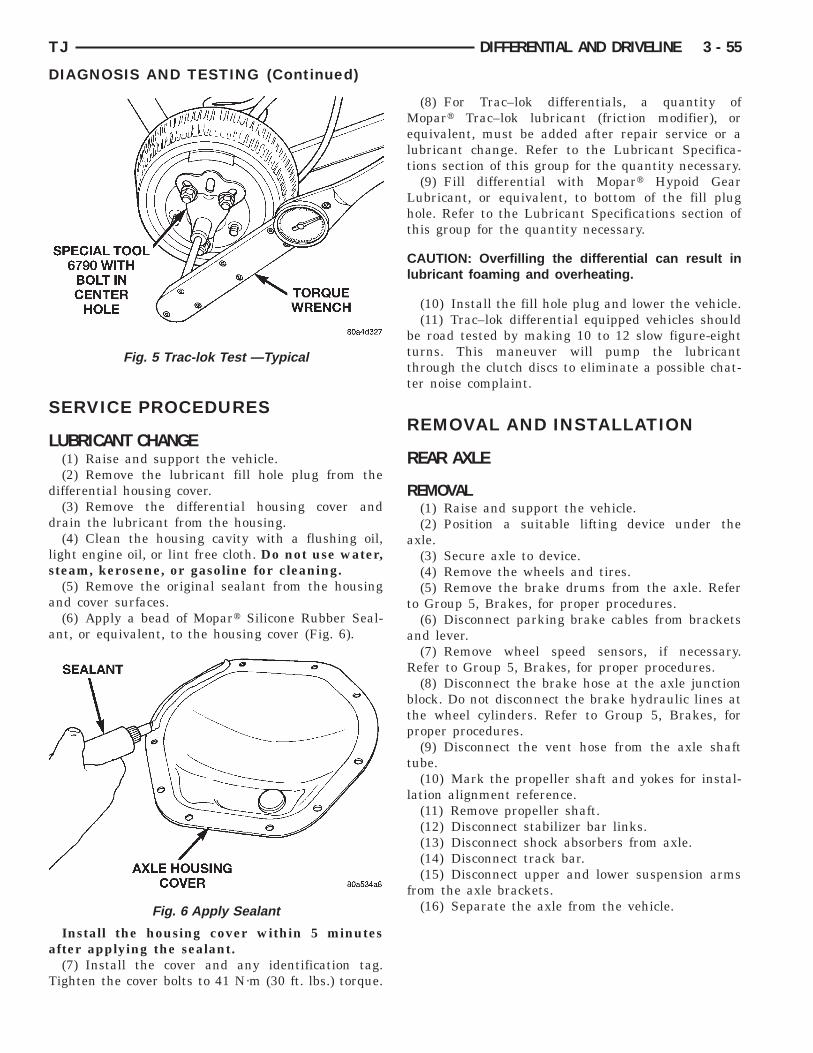
S
L
d
d
ls
a
a
a
T
TJ DIFFERENTIAL AND DRIVELINE 3 - 55
DIAGNOSIS AND TESTING (Continued)
ERVICE PROCEDURES
UBRICANT CHANGE(1) Raise and support the vehicle.(2) Remove the lubricant fill hole plug from the
ifferential housing cover.(3) Remove the differential housing cover and
rain the lubricant from the housing.(4) Clean the housing cavity with a flushing oil,
ight engine oil, or lint free cloth. Do not use water,team, kerosene, or gasoline for cleaning.(5) Remove the original sealant from the housing
nd cover surfaces.(6) Apply a bead of Mopart Silicone Rubber Seal-
nt, or equivalent, to the housing cover (Fig. 6).
Install the housing cover within 5 minutesfter applying the sealant.(7) Install the cover and any identification tag.
ighten the cover bolts to 41 N·m (30 ft. lbs.) torque.
Fig. 5 Trac-lok Test —Typical
Fig. 6 Apply Sealant
(8) For Trac–lok differentials, a quantity ofMopart Trac–lok lubricant (friction modifier), orequivalent, must be added after repair service or alubricant change. Refer to the Lubricant Specifica-tions section of this group for the quantity necessary.
(9) Fill differential with Mopart Hypoid GearLubricant, or equivalent, to bottom of the fill plughole. Refer to the Lubricant Specifications section ofthis group for the quantity necessary.
CAUTION: Overfilling the differential can result inlubricant foaming and overheating.
(10) Install the fill hole plug and lower the vehicle.(11) Trac–lok differential equipped vehicles should
be road tested by making 10 to 12 slow figure-eightturns. This maneuver will pump the lubricantthrough the clutch discs to eliminate a possible chat-ter noise complaint.
REMOVAL AND INSTALLATION
REAR AXLE
REMOVAL(1) Raise and support the vehicle.(2) Position a suitable lifting device under the
axle.(3) Secure axle to device.(4) Remove the wheels and tires.(5) Remove the brake drums from the axle. Refer
to Group 5, Brakes, for proper procedures.(6) Disconnect parking brake cables from brackets
and lever.(7) Remove wheel speed sensors, if necessary.
Refer to Group 5, Brakes, for proper procedures.(8) Disconnect the brake hose at the axle junction
block. Do not disconnect the brake hydraulic lines atthe wheel cylinders. Refer to Group 5, Brakes, forproper procedures.
(9) Disconnect the vent hose from the axle shafttube.
(10) Mark the propeller shaft and yokes for instal-lation alignment reference.
(11) Remove propeller shaft.(12) Disconnect stabilizer bar links.(13) Disconnect shock absorbers from axle.(14) Disconnect track bar.(15) Disconnect upper and lower suspension arms
from the axle brackets.(16) Separate the axle from the vehicle.
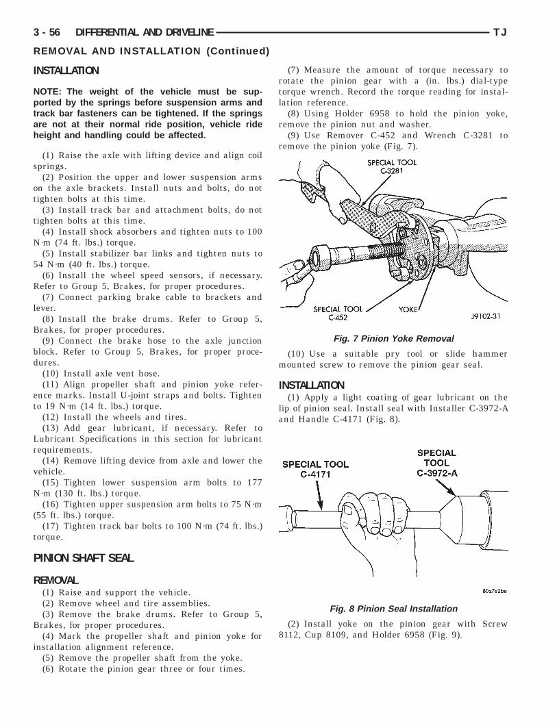
I
Nptah
s
ot
t
N
5
R
l
B
bd
et
Lr
v
N
(
t
P
R
B
i
3 - 56 DIFFERENTIAL AND DRIVELINE TJ
REMOVAL AND INSTALLATION (Continued)
NSTALLATION
OTE: The weight of the vehicle must be sup-orted by the springs before suspension arms and
rack bar fasteners can be tightened. If the springsre not at their normal ride position, vehicle rideeight and handling could be affected.
(1) Raise the axle with lifting device and align coilprings.(2) Position the upper and lower suspension arms
n the axle brackets. Install nuts and bolts, do notighten bolts at this time.
(3) Install track bar and attachment bolts, do notighten bolts at this time.
(4) Install shock absorbers and tighten nuts to 100·m (74 ft. lbs.) torque.(5) Install stabilizer bar links and tighten nuts to
4 N·m (40 ft. lbs.) torque.(6) Install the wheel speed sensors, if necessary.efer to Group 5, Brakes, for proper procedures.(7) Connect parking brake cable to brackets and
ever.(8) Install the brake drums. Refer to Group 5,rakes, for proper procedures.(9) Connect the brake hose to the axle junction
lock. Refer to Group 5, Brakes, for proper proce-ures.(10) Install axle vent hose.(11) Align propeller shaft and pinion yoke refer-
nce marks. Install U-joint straps and bolts. Tighteno 19 N·m (14 ft. lbs.) torque.
(12) Install the wheels and tires.(13) Add gear lubricant, if necessary. Refer to
ubricant Specifications in this section for lubricantequirements.(14) Remove lifting device from axle and lower the
ehicle.(15) Tighten lower suspension arm bolts to 177·m (130 ft. lbs.) torque.(16) Tighten upper suspension arm bolts to 75 N·m
55 ft. lbs.) torque.(17) Tighten track bar bolts to 100 N·m (74 ft. lbs.)
orque.
INION SHAFT SEAL
EMOVAL(1) Raise and support the vehicle.(2) Remove wheel and tire assemblies.(3) Remove the brake drums. Refer to Group 5,rakes, for proper procedures.(4) Mark the propeller shaft and pinion yoke for
nstallation alignment reference.(5) Remove the propeller shaft from the yoke.(6) Rotate the pinion gear three or four times.
(7) Measure the amount of torque necessary torotate the pinion gear with a (in. lbs.) dial-typetorque wrench. Record the torque reading for instal-lation reference.
(8) Using Holder 6958 to hold the pinion yoke,remove the pinion nut and washer.
(9) Use Remover C-452 and Wrench C-3281 toremove the pinion yoke (Fig. 7).
(10) Use a suitable pry tool or slide hammermounted screw to remove the pinion gear seal.
INSTALLATION(1) Apply a light coating of gear lubricant on the
lip of pinion seal. Install seal with Installer C-3972-Aand Handle C-4171 (Fig. 8).
(2) Install yoke on the pinion gear with Screw8112, Cup 8109, and Holder 6958 (Fig. 9).
Fig. 7 Pinion Yoke Removal
Fig. 8 Pinion Seal Installation

CtDr
pz
Cdntls
wiN
hsp
Crta
ps
ig
B
TJ DIFFERENTIAL AND DRIVELINE 3 - 57
REMOVAL AND INSTALLATION (Continued)
AUTION: Do not exceed the minimum tighteningorque when installing the pinion yoke at this point.amage to the collapsible spacer or bearings may
esult.
(3) Install the yoke washer and a new nut on theinion gear and tighten the pinion nut until there isero bearing end-play.(4) Tighten the nut to 271 N·m (200 ft. lbs.).
AUTION: Never loosen pinion gear nut toecrease pinion gear bearing rotating torque andever exceed specified preload torque. If preload
orque or rotating torque is exceeded a new col-apsible spacer must be installed. The torqueequence will then have to be repeated.
(5) Rotate the pinion shaft using a (in. lbs.) torquerench. Rotating torque should be equal to the read-
ng recorded during removal plus an additional 0.56·m (5 in. lbs.) (Fig. 10).(6) If the rotating torque is low, use Holder 6958 to
old the pinion yoke (Fig. 11), and tighten the pinionhaft nut in 6.8 N·m (5 ft. lbs.) increments until theroper rotating torque is achieved.
AUTION: If the maximum tightening torque iseached prior to reaching the required rotatingorque, the collapsible spacer may have been dam-ged. Replace the collapsible spacer.
(7) Align the installation reference marks on theropeller shaft and yoke and install the propellerhaft.(8) Add gear lubricant to the differential housing,
f necessary. Refer to the Lubricant Specifications forear lubricant requirements.(9) Install the brake drums. Refer to Group 5,rakes, for proper procedures.(10) Install wheel and tire assemblies.(11) Lower the vehicle.
Fig. 9 Pinion Yoke Installation
COLLAPSIBLE SPACER
REMOVAL W/PINION INSTALLED(1) Raise and support the vehicle.(2) Remove wheel and tire assemblies.(3) Remove rear brake drums. Refer to Group 5,
Brakes, for proper procedures.(4) Mark the propeller shaft and pinion yoke for
installation reference.(5) Remove the propeller shaft from the yoke.(6) Rotate the pinion gear three or four times.(7) Measure the amount of torque necessary to
rotate the pinion gear with a (in. lbs.) dial-typetorque wrench. Record the torque reading for instal-lation reference.
Fig. 10 Check Pinion Rotation Torque
Fig. 11 Tightening Pinion Shaft Nut

r
r
m
ottbi
R
B
i
rtl
i
p
r
1f
3 - 58 DIFFERENTIAL AND DRIVELINE TJ
REMOVAL AND INSTALLATION (Continued)
(8) Using Holder 6958 to hold the pinion yoke,emove the pinion nut and washer.(9) Use Remover C-452 and Wrench C-3281 to
emove the pinion yoke (Fig. 12).(10) Use a suitable pry tool or a slide hammerounted screw to remove the pinion shaft seal.(11) Remove the front pinion bearing using a pair
f suitable pick tools to pull the bearing straight offhe pinion gear shaft. It may be necessary to lightlyap the end of the pinion gear with a rawhide or rub-er mallet if the bearing becomes bound on the pin-on shaft.
(12) Remove the collapsible spacer.
EMOVAL W/PINION REMOVED(1) Raise and support the vehicle.(2) Remove wheel and tire assemblies.(3) Remove rear brake drums. Refer to Group 5,rakes, for proper procedures.(4) Mark the propeller shaft and pinion yoke for
nstallation reference.(5) Remove the propeller shaft from the yoke.(6) Rotate the pinion gear three or four times.(7) Measure the amount of torque necessary to
otate the pinion gear with a (in. lbs.) dial-typeorque wrench. Record the torque reading for instal-ation reference.
(8) Remove differential assembly from axle hous-ng.
(9) Using Holder 6958 to hold yoke, remove theinion yoke nut and washer.(10) Using Remover C–452 and Wrench C–3281,
emove the pinion yoke from pinion shaft (Fig. 12).(11) Remove the pinion gear from housing (Fig.
3). Catch the pinion with your hand to prevent itrom falling and being damaged.
(12) Remove collapsible spacer from pinion shaft.
Fig. 12 Pinion Yoke Removal
INSTALLATION(1) Install a new collapsible preload spacer on pin-
ion shaft (Fig. 14).(2) If pinion gear was removed, install pinion gear
in housing.
(3) Install pinion front bearing, if necessary.(4) Apply a light coating of gear lubricant on the
lip of pinion seal. Install seal with Installer C-3972-Aand Handle C–4171 (Fig. 15).
Fig. 13 Remove Pinion Gear
Fig. 14 Collapsible Preload Spacer
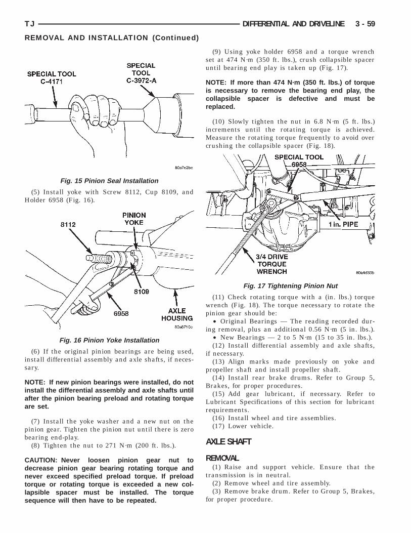
H
is
Niaa
pb
Cdntls
TJ DIFFERENTIAL AND DRIVELINE 3 - 59
REMOVAL AND INSTALLATION (Continued)
(5) Install yoke with Screw 8112, Cup 8109, andolder 6958 (Fig. 16).
(6) If the original pinion bearings are being used,nstall differential assembly and axle shafts, if neces-ary.
OTE: If new pinion bearings were installed, do notnstall the differential assembly and axle shafts untilfter the pinion bearing preload and rotating torquere set.
(7) Install the yoke washer and a new nut on theinion gear. Tighten the pinion nut until there is zeroearing end-play.(8) Tighten the nut to 271 N·m (200 ft. lbs.).
AUTION: Never loosen pinion gear nut toecrease pinion gear bearing rotating torque andever exceed specified preload torque. If preload
orque or rotating torque is exceeded a new col-apsible spacer must be installed. The torqueequence will then have to be repeated.
Fig. 15 Pinion Seal Installation
Fig. 16 Pinion Yoke Installation
(9) Using yoke holder 6958 and a torque wrenchset at 474 N·m (350 ft. lbs.), crush collapsible spaceruntil bearing end play is taken up (Fig. 17).
NOTE: If more than 474 N·m (350 ft. lbs.) of torqueis necessary to remove the bearing end play, thecollapsible spacer is defective and must bereplaced.
(10) Slowly tighten the nut in 6.8 N·m (5 ft. lbs.)increments until the rotating torque is achieved.Measure the rotating torque frequently to avoid overcrushing the collapsible spacer (Fig. 18).
(11) Check rotating torque with a (in. lbs.) torquewrench (Fig. 18). The torque necessary to rotate thepinion gear should be:
• Original Bearings — The reading recorded dur-ing removal, plus an additional 0.56 N·m (5 in. lbs.).
• New Bearings — 2 to 5 N·m (15 to 35 in. lbs.).(12) Install differential assembly and axle shafts,
if necessary.(13) Align marks made previously on yoke and
propeller shaft and install propeller shaft.(14) Install rear brake drums. Refer to Group 5,
Brakes, for proper procedures.(15) Add gear lubricant, if necessary. Refer to
Lubricant Specifications of this section for lubricantrequirements.
(16) Install wheel and tire assemblies.(17) Lower vehicle.
AXLE SHAFT
REMOVAL(1) Raise and support vehicle. Ensure that the
transmission is in neutral.(2) Remove wheel and tire assembly.(3) Remove brake drum. Refer to Group 5, Brakes,
for proper procedure.
Fig. 17 Tightening Pinion Nut
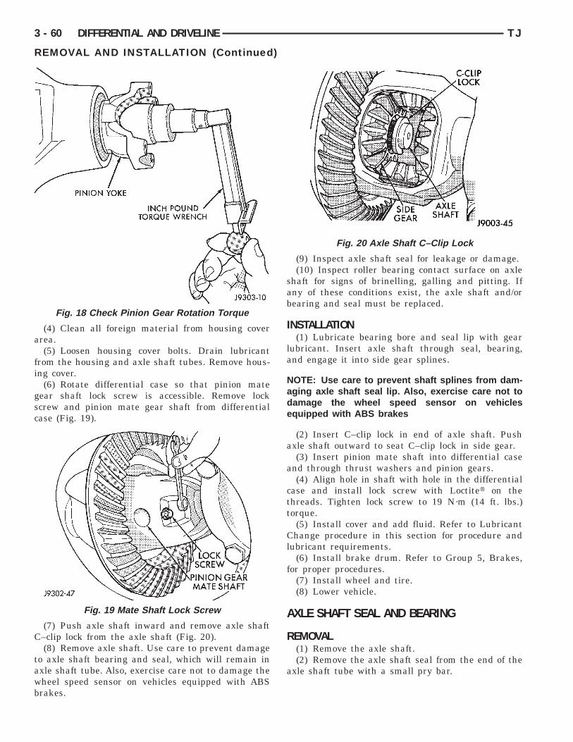
a
fi
gsc
C
tawb
3 - 60 DIFFERENTIAL AND DRIVELINE TJ
REMOVAL AND INSTALLATION (Continued)
(4) Clean all foreign material from housing coverrea.(5) Loosen housing cover bolts. Drain lubricant
rom the housing and axle shaft tubes. Remove hous-ng cover.
(6) Rotate differential case so that pinion mateear shaft lock screw is accessible. Remove lockcrew and pinion mate gear shaft from differentialase (Fig. 19).
(7) Push axle shaft inward and remove axle shaft–clip lock from the axle shaft (Fig. 20).(8) Remove axle shaft. Use care to prevent damage
o axle shaft bearing and seal, which will remain inxle shaft tube. Also, exercise care not to damage theheel speed sensor on vehicles equipped with ABSrakes.
Fig. 18 Check Pinion Gear Rotation Torque
Fig. 19 Mate Shaft Lock Screw
(9) Inspect axle shaft seal for leakage or damage.(10) Inspect roller bearing contact surface on axle
shaft for signs of brinelling, galling and pitting. Ifany of these conditions exist, the axle shaft and/orbearing and seal must be replaced.
INSTALLATION(1) Lubricate bearing bore and seal lip with gear
lubricant. Insert axle shaft through seal, bearing,and engage it into side gear splines.
NOTE: Use care to prevent shaft splines from dam-aging axle shaft seal lip. Also, exercise care not todamage the wheel speed sensor on vehiclesequipped with ABS brakes
(2) Insert C–clip lock in end of axle shaft. Pushaxle shaft outward to seat C–clip lock in side gear.
(3) Insert pinion mate shaft into differential caseand through thrust washers and pinion gears.
(4) Align hole in shaft with hole in the differentialcase and install lock screw with Loctitet on thethreads. Tighten lock screw to 19 N·m (14 ft. lbs.)torque.
(5) Install cover and add fluid. Refer to LubricantChange procedure in this section for procedure andlubricant requirements.
(6) Install brake drum. Refer to Group 5, Brakes,for proper procedures.
(7) Install wheel and tire.(8) Lower vehicle.
AXLE SHAFT SEAL AND BEARING
REMOVAL(1) Remove the axle shaft.(2) Remove the axle shaft seal from the end of the
axle shaft tube with a small pry bar.
Fig. 20 Axle Shaft C–Clip Lock
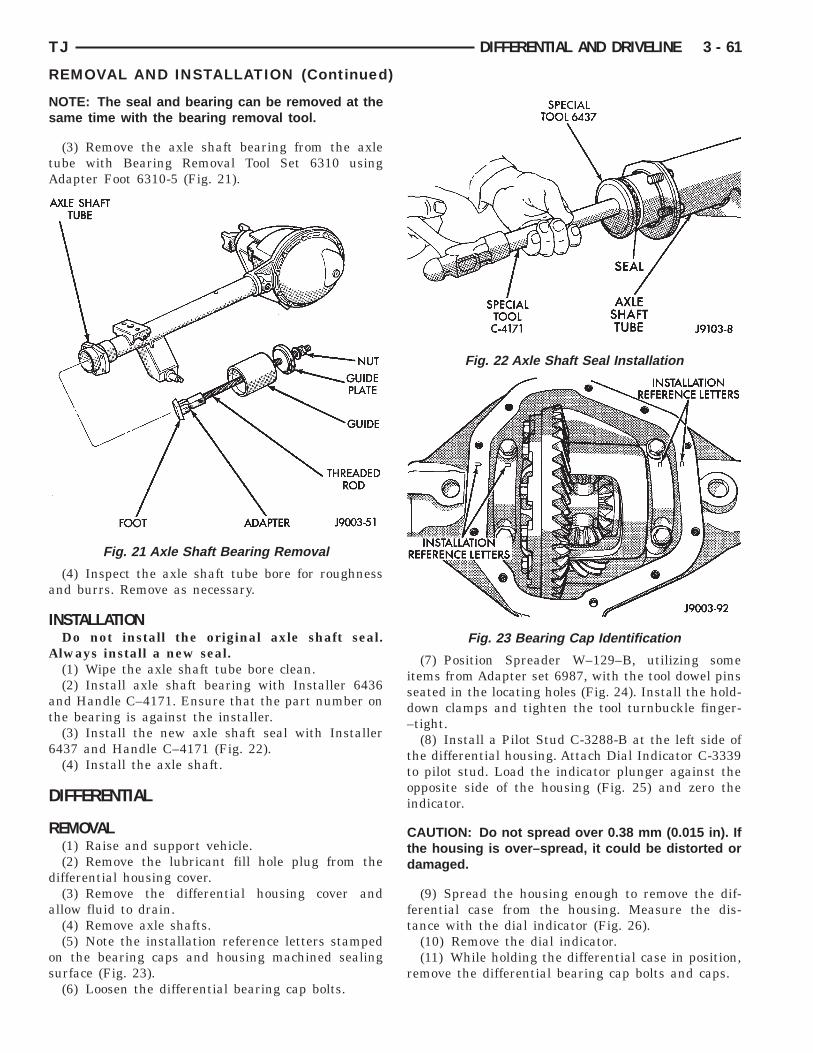
Ns
tA
a
I
A
at
6
D
R
d
a
os
TJ DIFFERENTIAL AND DRIVELINE 3 - 61
REMOVAL AND INSTALLATION (Continued)
OTE: The seal and bearing can be removed at theame time with the bearing removal tool.
(3) Remove the axle shaft bearing from the axleube with Bearing Removal Tool Set 6310 usingdapter Foot 6310-5 (Fig. 21).
(4) Inspect the axle shaft tube bore for roughnessnd burrs. Remove as necessary.
NSTALLATIONDo not install the original axle shaft seal.lways install a new seal.(1) Wipe the axle shaft tube bore clean.(2) Install axle shaft bearing with Installer 6436
nd Handle C–4171. Ensure that the part number onhe bearing is against the installer.
(3) Install the new axle shaft seal with Installer437 and Handle C–4171 (Fig. 22).(4) Install the axle shaft.
IFFERENTIAL
EMOVAL(1) Raise and support vehicle.(2) Remove the lubricant fill hole plug from the
ifferential housing cover.(3) Remove the differential housing cover and
llow fluid to drain.(4) Remove axle shafts.(5) Note the installation reference letters stamped
n the bearing caps and housing machined sealingurface (Fig. 23).(6) Loosen the differential bearing cap bolts.
Fig. 21 Axle Shaft Bearing Removal
(7) Position Spreader W–129–B, utilizing someitems from Adapter set 6987, with the tool dowel pinsseated in the locating holes (Fig. 24). Install the hold-down clamps and tighten the tool turnbuckle finger-–tight.
(8) Install a Pilot Stud C-3288-B at the left side ofthe differential housing. Attach Dial Indicator C-3339to pilot stud. Load the indicator plunger against theopposite side of the housing (Fig. 25) and zero theindicator.
CAUTION: Do not spread over 0.38 mm (0.015 in). Ifthe housing is over–spread, it could be distorted ordamaged.
(9) Spread the housing enough to remove the dif-ferential case from the housing. Measure the dis-tance with the dial indicator (Fig. 26).
(10) Remove the dial indicator.(11) While holding the differential case in position,
remove the differential bearing cap bolts and caps.
Fig. 22 Axle Shaft Seal Installation
Fig. 23 Bearing Cap Identification
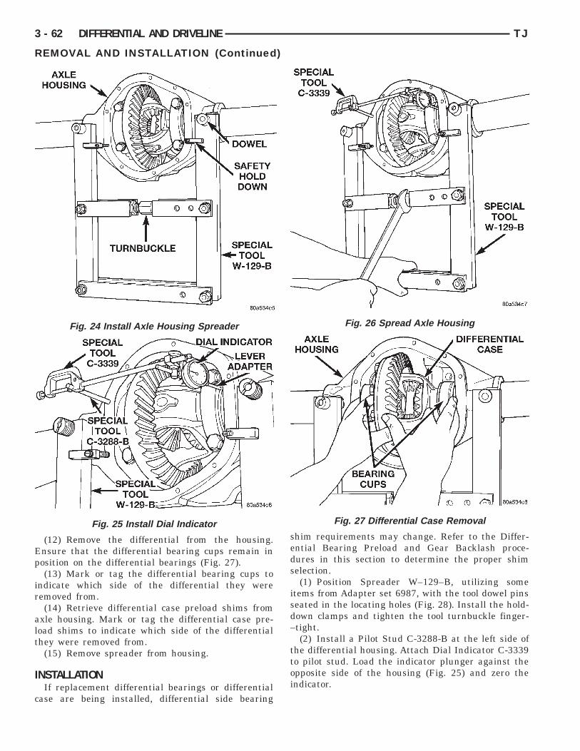
Ep
ir
alt
I
c
3 - 62 DIFFERENTIAL AND DRIVELINE TJ
REMOVAL AND INSTALLATION (Continued)
(12) Remove the differential from the housing.nsure that the differential bearing cups remain inosition on the differential bearings (Fig. 27).(13) Mark or tag the differential bearing cups to
ndicate which side of the differential they wereemoved from.(14) Retrieve differential case preload shims from
xle housing. Mark or tag the differential case pre-oad shims to indicate which side of the differentialhey were removed from.
(15) Remove spreader from housing.
NSTALLATIONIf replacement differential bearings or differential
ase are being installed, differential side bearing
Fig. 24 Install Axle Housing Spreader
Fig. 25 Install Dial Indicator
shim requirements may change. Refer to the Differ-ential Bearing Preload and Gear Backlash proce-dures in this section to determine the proper shimselection.(1) Position Spreader W–129–B, utilizing someitems from Adapter set 6987, with the tool dowel pinsseated in the locating holes (Fig. 28). Install the hold-down clamps and tighten the tool turnbuckle finger-–tight.
(2) Install a Pilot Stud C-3288-B at the left side ofthe differential housing. Attach Dial Indicator C-3339to pilot stud. Load the indicator plunger against theopposite side of the housing (Fig. 25) and zero theindicator.
Fig. 26 Spread Axle Housing
Fig. 27 Differential Case Removal
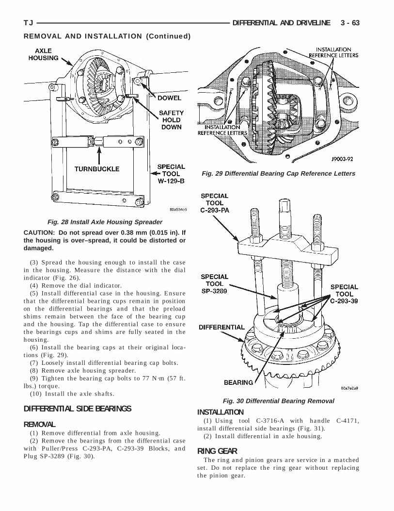
Ctd
ii
tosath
t
l
D
R
wP
TJ DIFFERENTIAL AND DRIVELINE 3 - 63
REMOVAL AND INSTALLATION (Continued)
AUTION: Do not spread over 0.38 mm (0.015 in). Ifhe housing is over–spread, it could be distorted oramaged.
(3) Spread the housing enough to install the casen the housing. Measure the distance with the dialndicator (Fig. 26).
(4) Remove the dial indicator.(5) Install differential case in the housing. Ensure
hat the differential bearing cups remain in positionn the differential bearings and that the preloadhims remain between the face of the bearing cupnd the housing. Tap the differential case to ensurehe bearings cups and shims are fully seated in theousing.(6) Install the bearing caps at their original loca-
ions (Fig. 29).(7) Loosely install differential bearing cap bolts.(8) Remove axle housing spreader.(9) Tighten the bearing cap bolts to 77 N·m (57 ft.
bs.) torque.(10) Install the axle shafts.
IFFERENTIAL SIDE BEARINGS
EMOVAL(1) Remove differential from axle housing.(2) Remove the bearings from the differential caseith Puller/Press C-293-PA, C-293-39 Blocks, andlug SP-3289 (Fig. 30).
Fig. 28 Install Axle Housing Spreader
INSTALLATION(1) Using tool C-3716-A with handle C-4171,
install differential side bearings (Fig. 31).(2) Install differential in axle housing.
RING GEARThe ring and pinion gears are service in a matched
set. Do not replace the ring gear without replacingthe pinion gear.
Fig. 29 Differential Bearing Cap Reference Letters
Fig. 30 Differential Bearing Removal

R
s
c
f
I
Cgc
3 - 64 DIFFERENTIAL AND DRIVELINE TJ
REMOVAL AND INSTALLATION (Continued)
EMOVAL(1) Remove differential from axle housing.(2) Place differential case in a suitable vise with
oft metal jaw protectors. (Fig. 32)(3) Remove bolts holding ring gear to differential
ase.(4) Using a soft hammer, drive ring gear from dif-
erential case (Fig. 32).
NSTALLATION
AUTION: Do not reuse the bolts that held the ringear to the differential case. The bolts can fractureausing extensive damage.
Fig. 31 Install Differential Side Bearings
Fig. 32 Ring Gear Removal
(1) Invert the differential case and start two ringgear bolts. This will provide case-to-ring gear bolthole alignment.
(2) Invert the differential case in the vise.(3) Install new ring gear bolts and alternately
tighten to 95–122 N·m (70–90 ft. lbs.) torque (Fig.33).
(4) Install differential in axle housing and verifygear mesh and contact pattern.
PINION GEARThe ring and pinion gears are serviced in a
matched set. Do not replace the pinion gear withoutreplacing the ring gear.
REMOVAL(1) Remove differential from the axle housing.(2) Mark pinion yoke and propeller shaft for
installation alignment.(3) Disconnect propeller shaft from pinion yoke.
Using suitable wire, tie propeller shaft to underbody.(4) Using Holder 6958 to hold yoke, remove the
pinion yoke nut and washer.(5) Using Remover C–452 and Wrench C–3281,
remove the pinion yoke from pinion shaft (Fig. 34).(6) Remove the pinion gear from housing (Fig. 35).
Catch the pinion with your hand to prevent it fromfalling and being damaged.
(7) Use a suitable pry tool or a slide hammermounted screw to remove the pinion shaft seal.
(8) Remove oil slinger, if equipped, and front pin-ion bearing.
(9) Remove the front pinion bearing cup withRemover C-4345 and Handle C–4171 (Fig. 36).
Fig. 33 Ring Gear Bolt Installation

(
3
P3
t
s
I
l
TJ DIFFERENTIAL AND DRIVELINE 3 - 65
REMOVAL AND INSTALLATION (Continued)
(10) Remove the rear bearing cup from housingFig. 37). Use Remover D-149 and Handle C–4171.
(11) Remove the collapsible preload spacer (Fig.8).(12) Remove the rear bearing from the pinion with
uller/Press C-293-PA and Adapters C-293-40 (Fig.9).Place 4 adapter blocks so they do not damage
he bearing cage.(13) Remove the depth shims from the pinion gear
haft. Record the thickness of the depth shims.
NSTALLATION(1) Apply Mopart Door Ease, or equivalent, stick
ubricant to outside surface of bearing cup.
Fig. 34 Pinion Yoke Removal
Fig. 35 Remove Pinion Gear
(2) Install the pinion rear bearing cup withInstaller D-146 and Driver Handle C–4171 (Fig. 40).Ensure cup is correctly seated.
(3) Apply Mopart Door Ease, or equivalent, sticklubricant to outside surface of bearing cup.
(4) Install the pinion front bearing cup withInstaller D–130 and Handle C–4171 (Fig. 41).
(5) Install pinion front bearing, and oil slinger, ifequipped.
(6) Apply a light coating of gear lubricant on thelip of pinion seal. Install seal with Installer C-3972-Aand Handle C–4171 (Fig. 42).
Fig. 36 Front Bearing Cup Removal
Fig. 37 Rear Bearing Cup Removal
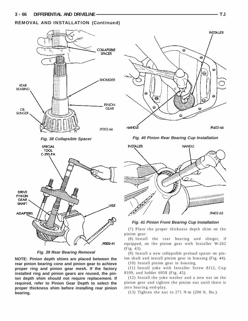
Nrpiirpb
3 - 66 DIFFERENTIAL AND DRIVELINE TJ
REMOVAL AND INSTALLATION (Continued)
OTE: Pinion depth shims are placed between theear pinion bearing cone and pinion gear to achieveroper ring and pinion gear mesh. If the factory
nstalled ring and pinion gears are reused, the pin-on depth shim should not require replacement. Ifequired, refer to Pinion Gear Depth to select theroper thickness shim before installing rear pinionearing.
Fig. 38 Collapsible Spacer
Fig. 39 Rear Bearing Removal
(7) Place the proper thickness depth shim on thepinion gear.
(8) Install the rear bearing and slinger, ifequipped, on the pinion gear with Installer W-262(Fig. 43).
(9) Install a new collapsible preload spacer on pin-ion shaft and install pinion gear in housing (Fig. 44).
(10) Install pinion gear in housing.(11) Install yoke with Installer Screw 8112, Cup
8109, and holder 6958 (Fig. 45).(12) Install the yoke washer and a new nut on the
pinion gear and tighten the pinion nut until there iszero bearing end-play.
(13) Tighten the nut to 271 N·m (200 ft. lbs.).
Fig. 40 Pinion Rear Bearing Cup Installation
Fig. 41 Pinion Front Bearing Cup Installation

Cdntls
su
N(i
TJ DIFFERENTIAL AND DRIVELINE 3 - 67
REMOVAL AND INSTALLATION (Continued)
AUTION: Never loosen pinion gear nut toecrease pinion gear bearing rotating torque andever exceed specified preload torque. If preload
orque or rotating torque is exceeded a new col-apsible spacer must be installed. The torqueequence will then have to be repeated.
(14) Using yoke holder 6958 and a torque wrenchet at 474 N·m (350 ft. lbs.), crush collapsible spacerntil bearing end play is taken up (Fig. 46).
OTE: If the spacer requires more than 474 N·m350 ft. lbs.) torque to crush, the collapsible spacers defective and must be replaced.
Fig. 42 Pinion Seal Installation
Fig. 43 Shaft Rear Bearing Installation
(15) Slowly tighten the nut in 6.8 N·m (5 ft. lbs.)increments until the rotating torque is achieved.Measure the rotating torque frequently to avoid overcrushing the collapsible spacer (Fig. 47).
(16) Check bearing rotating torque with a (in. lbs.)torque wrench (Fig. 47). The torque necessary torotate the pinion gear should be:
• Original Bearings — 1 to 3 N·m (10 to 20 in.lbs.).
• New Bearings — 2 to 5 N·m (15 to 35 in. lbs.).(17) Install differential in housing.
FINAL ASSEMBLY(1) Scrape the residual sealant from the housing
and cover mating surfaces. Clean the mating surfaces
Fig. 44 Collapsible Preload Spacer
Fig. 45 Pinion Yoke Installation

wR(
a
at
Cl
ct
3 - 68 DIFFERENTIAL AND DRIVELINE TJ
REMOVAL AND INSTALLATION (Continued)
ith mineral spirits. Apply a bead of Mopart Siliconeubber Sealant, or equivalent, on the housing cover
Fig. 48).Install the housing cover within 5 minutes
fter applying the sealant.(2) Install the cover on the differential with the
ttaching bolts. Install the identification tag. Tightenhe cover bolts to 41 N·m (30 ft. lbs.) torque.
AUTION: Overfilling the differential can result inubricant foaming and overheating.
(3) Refill the differential housing with gear lubri-ant. Refer to the Lubricant Specifications section ofhis group for the gear lubricant requirements.
(4) Install the fill hole plug.
Fig. 46 Tightening Pinion Nut
Fig. 47 Check Pinion Gear Rotating Torque
DISASSEMBLY AND ASSEMBLY
STANDARD DIFFERENTIAL
DISASSEMBLY(1) Remove pinion gear mate shaft lock screw (Fig.
49).(2) Remove pinion gear mate shaft.(3) Rotate the differential side gears and remove
the pinion mate gears and thrust washers (Fig. 50).
(4) Remove the differential side gears and thrustwashers.
Fig. 48 Typical Housing Cover With Sealant
Fig. 49 Pinion Gear Mate Shaft Lock Screw
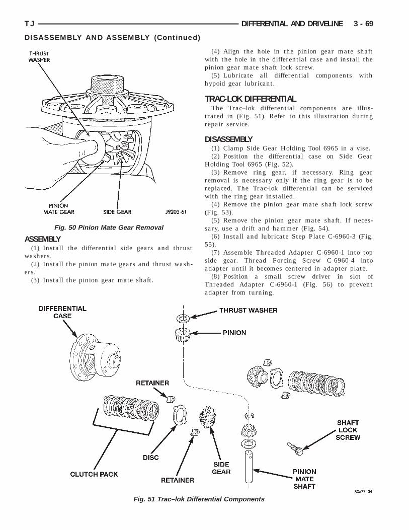
A
w
e
TJ DIFFERENTIAL AND DRIVELINE 3 - 69
DISASSEMBLY AND ASSEMBLY (Continued)
SSEMBLY(1) Install the differential side gears and thrustashers.(2) Install the pinion mate gears and thrust wash-
rs.(3) Install the pinion gear mate shaft.
Fig. 50 Pinion Mate Gear Removal
Fig. 51 Trac–lok Differen
(4) Align the hole in the pinion gear mate shaftwith the hole in the differential case and install thepinion gear mate shaft lock screw.
(5) Lubricate all differential components withhypoid gear lubricant.
TRAC-LOK DIFFERENTIALThe Trac–lok differential components are illus-
trated in (Fig. 51). Refer to this illustration duringrepair service.
DISASSEMBLY(1) Clamp Side Gear Holding Tool 6965 in a vise.(2) Position the differential case on Side Gear
Holding Tool 6965 (Fig. 52).(3) Remove ring gear, if necessary. Ring gear
removal is necessary only if the ring gear is to bereplaced. The Trac-lok differential can be servicedwith the ring gear installed.
(4) Remove the pinion gear mate shaft lock screw(Fig. 53).
(5) Remove the pinion gear mate shaft. If neces-sary, use a drift and hammer (Fig. 54).
(6) Install and lubricate Step Plate C-6960-3 (Fig.55).
(7) Assemble Threaded Adapter C-6960-1 into topside gear. Thread Forcing Screw C-6960-4 intoadapter until it becomes centered in adapter plate.
(8) Position a small screw driver in slot ofThreaded Adapter C-6960-1 (Fig. 56) to preventadapter from turning.
tial Components
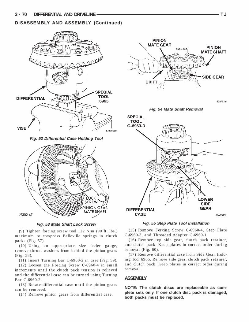
mp
r(
iaB
c
3 - 70 DIFFERENTIAL AND DRIVELINE TJ
DISASSEMBLY AND ASSEMBLY (Continued)
(9) Tighten forcing screw tool 122 N·m (90 ft. lbs.)aximum to compress Belleville springs in clutch
acks (Fig. 57).(10) Using an appropriate size feeler gauge,
emove thrust washers from behind the pinion gearsFig. 58).
(11) Insert Turning Bar C-6960-2 in case (Fig. 59).(12) Loosen the Forcing Screw C-6960-4 in small
ncrements until the clutch pack tension is relievednd the differential case can be turned using Turningar C-6960-2.(13) Rotate differential case until the pinion gears
an be removed.(14) Remove pinion gears from differential case.
Fig. 52 Differential Case Holding Tool
Fig. 53 Mate Shaft Lock Screw
(15) Remove Forcing Screw C-6960-4, Step PlateC-6960-3, and Threaded Adapter C-6960-1.(16) Remove top side gear, clutch pack retainer,
and clutch pack. Keep plates in correct order duringremoval (Fig. 60).
(17) Remove differential case from Side Gear Hold-ing Tool 6965. Remove side gear, clutch pack retainer,and clutch pack. Keep plates in correct order duringremoval.
ASSEMBLY
NOTE: The clutch discs are replaceable as com-plete sets only. If one clutch disc pack is damaged,both packs must be replaced.
Fig. 54 Mate Shaft Removal
Fig. 55 Step Plate Tool Installation
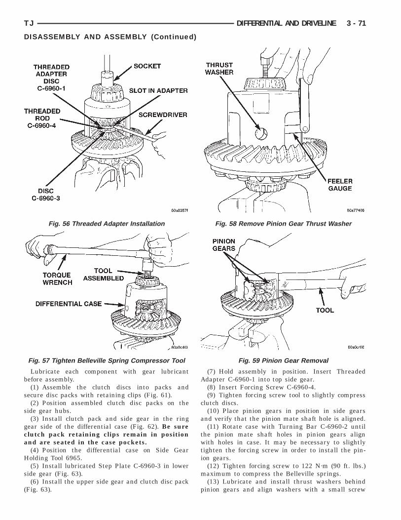
b
s
s
gca
H
s
(
TJ DIFFERENTIAL AND DRIVELINE 3 - 71
DISASSEMBLY AND ASSEMBLY (Continued)
Lubricate each component with gear lubricantefore assembly.(1) Assemble the clutch discs into packs and
ecure disc packs with retaining clips (Fig. 61).(2) Position assembled clutch disc packs on the
ide gear hubs.(3) Install clutch pack and side gear in the ring
ear side of the differential case (Fig. 62). Be surelutch pack retaining clips remain in positionnd are seated in the case pockets.(4) Position the differential case on Side Gearolding Tool 6965.(5) Install lubricated Step Plate C-6960-3 in lower
ide gear (Fig. 63).(6) Install the upper side gear and clutch disc pack
Fig. 63).
Fig. 56 Threaded Adapter Installation
Fig. 57 Tighten Belleville Spring Compressor Tool
(7) Hold assembly in position. Insert ThreadedAdapter C-6960-1 into top side gear.
(8) Insert Forcing Screw C-6960-4.(9) Tighten forcing screw tool to slightly compress
clutch discs.(10) Place pinion gears in position in side gears
and verify that the pinion mate shaft hole is aligned.(11) Rotate case with Turning Bar C-6960-2 until
the pinion mate shaft holes in pinion gears alignwith holes in case. It may be necessary to slightlytighten the forcing screw in order to install the pin-ion gears.
(12) Tighten forcing screw to 122 N·m (90 ft. lbs.)maximum to compress the Belleville springs.
(13) Lubricate and install thrust washers behindpinion gears and align washers with a small screw
Fig. 58 Remove Pinion Gear Thrust Washer
Fig. 59 Pinion Gear Removal
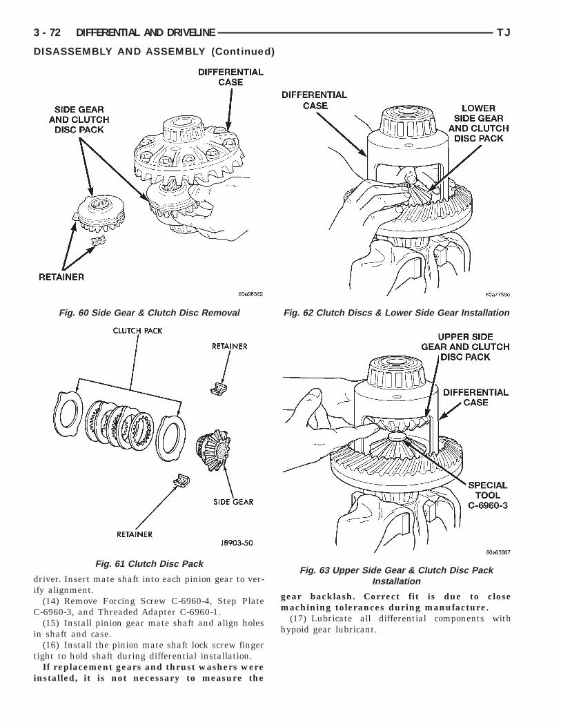
di
C
i
t
i
3 - 72 DIFFERENTIAL AND DRIVELINE TJ
DISASSEMBLY AND ASSEMBLY (Continued)
river. Insert mate shaft into each pinion gear to ver-fy alignment.
(14) Remove Forcing Screw C-6960-4, Step Plate-6960-3, and Threaded Adapter C-6960-1.(15) Install pinion gear mate shaft and align holes
n shaft and case.(16) Install the pinion mate shaft lock screw finger
ight to hold shaft during differential installation.If replacement gears and thrust washers were
nstalled, it is not necessary to measure the
Fig. 60 Side Gear & Clutch Disc Removal
Fig. 61 Clutch Disc Pack
gear backlash. Correct fit is due to closemachining tolerances during manufacture.
(17) Lubricate all differential components withhypoid gear lubricant.
Fig. 62 Clutch Discs & Lower Side Gear Installation
Fig. 63 Upper Side Gear & Clutch Disc PackInstallation
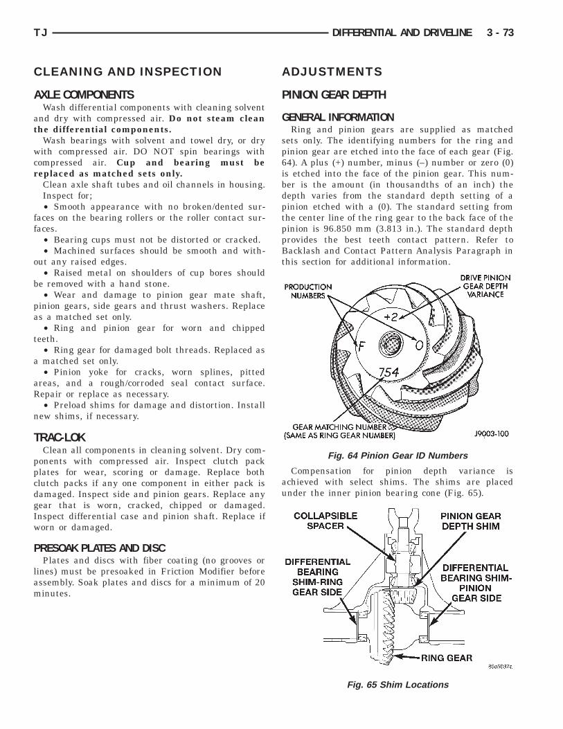
C
A
at
wcr
ff
o
b
pa
t
a
aR
n
T
ppcdgIw
P
lam
TJ DIFFERENTIAL AND DRIVELINE 3 - 73
LEANING AND INSPECTION
XLE COMPONENTSWash differential components with cleaning solvent
nd dry with compressed air. Do not steam cleanhe differential components.
Wash bearings with solvent and towel dry, or dryith compressed air. DO NOT spin bearings with
ompressed air. Cup and bearing must beeplaced as matched sets only.Clean axle shaft tubes and oil channels in housing.Inspect for;• Smooth appearance with no broken/dented sur-
aces on the bearing rollers or the roller contact sur-aces.
• Bearing cups must not be distorted or cracked.• Machined surfaces should be smooth and with-
ut any raised edges.• Raised metal on shoulders of cup bores should
e removed with a hand stone.• Wear and damage to pinion gear mate shaft,
inion gears, side gears and thrust washers. Replaces a matched set only.• Ring and pinion gear for worn and chipped
eeth.• Ring gear for damaged bolt threads. Replaced asmatched set only.• Pinion yoke for cracks, worn splines, pitted
reas, and a rough/corroded seal contact surface.epair or replace as necessary.• Preload shims for damage and distortion. Install
ew shims, if necessary.
RAC-LOKClean all components in cleaning solvent. Dry com-
onents with compressed air. Inspect clutch packlates for wear, scoring or damage. Replace bothlutch packs if any one component in either pack isamaged. Inspect side and pinion gears. Replace anyear that is worn, cracked, chipped or damaged.nspect differential case and pinion shaft. Replace iforn or damaged.
RESOAK PLATES AND DISCPlates and discs with fiber coating (no grooves or
ines) must be presoaked in Friction Modifier beforessembly. Soak plates and discs for a minimum of 20inutes.
ADJUSTMENTS
PINION GEAR DEPTH
GENERAL INFORMATIONRing and pinion gears are supplied as matched
sets only. The identifying numbers for the ring andpinion gear are etched into the face of each gear (Fig.64). A plus (+) number, minus (–) number or zero (0)is etched into the face of the pinion gear. This num-ber is the amount (in thousandths of an inch) thedepth varies from the standard depth setting of apinion etched with a (0). The standard setting fromthe center line of the ring gear to the back face of thepinion is 96.850 mm (3.813 in.). The standard depthprovides the best teeth contact pattern. Refer toBacklash and Contact Pattern Analysis Paragraph inthis section for additional information.
Compensation for pinion depth variance isachieved with select shims. The shims are placedunder the inner pinion bearing cone (Fig. 65).
Fig. 64 Pinion Gear ID Numbers
Fig. 65 Shim Locations

vmtea
im
prdrbonC
P
imA6
B(
rp
h
3 - 74 DIFFERENTIAL AND DRIVELINE TJ
ADJUSTMENTS (Continued)
If a new gear set is being installed, note the depthariance etched into both the original and replace-ent pinion gear. Add or subtract the thickness of
he original depth shims to compensate for the differ-nce in the depth variances. Refer to the Depth Vari-nce charts.Note where Old and New Pinion Marking columns
ntersect. Intersecting figure represents plus orinus amount needed.Note the etched number on the face of the drive
inion gear (–1, –2, 0, +1, +2, etc.). The numbers rep-esent thousands of an inch deviation from the stan-ard. If the number is negative, add that value to theequired thickness of the depth shim(s). If the num-er is positive, subtract that value from the thicknessf the depth shim(s). If the number is 0 no change isecessary. Refer to the Pinion Gear Depth Variancehart.
INION DEPTH MEASUREMENT AND ADJUSTMENTMeasurements are taken with pinion cups and pin-
on bearings installed in housing. Take measure-ents with a Pinion Gauge Set, Pinion Block 6735,rbor Discs 6732, and Dial Indicator C-3339 (Fig.6).(1) Assemble Pinion Height Block 6739, Pinionlock 6735, and rear pinion bearing onto Screw 6741
Fig. 66).(2) Insert assembled height gauge components,
ear bearing and screw into axle housing throughinion bearing cups (Fig. 67).(3) Install front pinion bearing and Cone 6740
and tight (Fig. 66).
PINION GEAR D
(4) Place Arbor Disc 6732 on Arbor D-115-3 in posi-tion in axle housing side bearing cradles (Fig. 68).Install differential bearing caps on Arbor Discs andtighten cap bolts. Refer to the Torque Specificationsin this section.
NOTE: Arbor Discs 6732 have different step diame-ters to fit other axle sizes. Pick correct size step foraxle being serviced.
TH VARIANCE
Fig. 66 Pinion Gear Depth Gauge Tools—Typical
EP

B
ifHtl
ppOdo
bw(tpt
TJ DIFFERENTIAL AND DRIVELINE 3 - 75
ADJUSTMENTS (Continued)
(5) Assemble Dial Indicator C-3339 into Scooterlock D-115-2 and secure set screw.(6) Place Scooter Block/Dial Indicator in position
n axle housing so dial probe and scooter block arelush against the surface of the pinion height block.old scooter block in place and zero the dial indica-
or face to the pointer. Tighten dial indicator faceock screw.
(7) With scooter block still in position against theinion height block, slowly slide the dial indicatorrobe over the edge of the pinion height block.bserve how many revolutions counterclockwise theial pointer travels (approximately 0.125 in.) to theut-stop of the dial indicator.(8) Slide the dial indicator probe across the gap
etween the pinion height block and the arbor barith the scooter block against the pinion height block
Fig. 69). When the dial probe contacts the arbor bar,he dial pointer will turn clockwise. Bring dialointer back to zero against the arbor bar, do noturn dial face. Continue moving the dial probe to the
Fig. 67 Pinion Height Block—Typical
Fig. 68 Gauge Tools In Housing—Typical
crest of the arbor bar and record the highest reading.If the dial indicator can not achieve the zero reading,the rear bearing cup or the pinion depth gauge set isnot installed correctly.
(9) Select a shim equal to the dial indicator read-ing plus the drive pinion gear depth variance numberetched in the face of the pinion gear (Fig. 64) usingthe opposite sign on the variance number. For exam-ple, if the depth variance is –2, add +0.002 in. to thedial indicator reading.
(10) Remove the pinion depth gauge componentsfrom the axle housing
DIFFERENTIAL BEARING PRELOAD AND GEARBACKLASH
Differential side bearing preload and gear backlashis achieved by selective shims inserted between thebearing cup and the axle housing. The proper shimthickness can be determined using slip-fit dummybearings D-348 in place of the differential side bear-ings and a dial indicator C-3339. Before proceedingwith the differential bearing preload and gear back-lash measurements, measure the pinion gear depthand prepare the pinion gear for installation. Estab-lishing proper pinion gear depth is essential to estab-lishing gear backlash and tooth contact patterns.After the overall shim thickness to take up differen-tial side play is measured, the pinion gear isinstalled, and the gear backlash shim thickness ismeasured. The overall shim thickness is the total ofthe dial indicator reading, starting point shim thick-ness, and the preload specification added together.The gear backlash measurement determines thethickness of the shim used on the ring gear side ofthe differential case. Subtract the gear backlash shimthickness from the total overall shim thickness andselect that amount for the pinion gear side of the dif-ferential (Fig. 70).
Fig. 69 Pinion Gear Depth Measurement—Typical
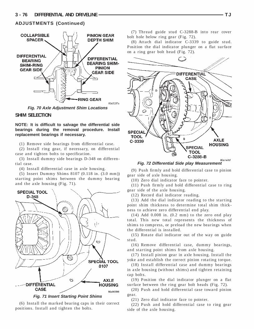
S
Nbr
c
t
sa
p
3 - 76 DIFFERENTIAL AND DRIVELINE TJ
ADJUSTMENTS (Continued)
HIM SELECTION
OTE: It is difficult to salvage the differential sideearings during the removal procedure. Installeplacement bearings if necessary.
(1) Remove side bearings from differential case.(2) Install ring gear, if necessary, on differential
ase and tighten bolts to specification.(3) Install dummy side bearings D-348 on differen-
ial case.(4) Install differential case in axle housing.(5) Insert Dummy Shims 8107 (0.118 in. (3.0 mm))
tarting point shims between the dummy bearingnd the axle housing (Fig. 71).
(6) Install the marked bearing caps in their correctositions. Install and tighten the bolts.
Fig. 70 Axle Adjustment Shim Locations
Fig. 71 Insert Starting Point Shims
(7) Thread guide stud C-3288-B into rear coverbolt hole below ring gear (Fig. 72).
(8) Attach dial indicator C-3339 to guide stud.Position the dial indicator plunger on a flat surfaceon a ring gear bolt head (Fig. 72).
(9) Push firmly and hold differential case to piniongear side of axle housing.
(10) Zero dial indicator face to pointer.(11) Push firmly and hold differential case to ring
gear side of the axle housing.(12) Record dial indicator reading.(13) Add the dial indicator reading to the starting
point shim thickness to determine total shim thick-ness to achieve zero differential end play.
(14) Add 0.008 in. (0.2 mm) to the zero end playtotal. This new total represents the thickness ofshims to compress, or preload the new bearings whenthe differential is installed.
(15) Rotate dial indicator out of the way on guidestud.
(16) Remove differential case, dummy bearings,and starting point shims from axle housing.
(17) Install pinion gear in axle housing. Install theyoke and establish the correct pinion rotating torque.
(18) Install differential case and dummy bearingsin axle housing (without shims) and tighten retainingcap bolts.
(19) Position the dial indicator plunger on a flatsurface between the ring gear bolt heads (Fig. 72).
(20) Push and hold differential case toward piniongear.
(21) Zero dial indicator face to pointer.(22) Push and hold differential case to ring gear
side of the axle housing.
Fig. 72 Differential Side play Measurement

irs
tta
s
f
d
psc
a
s
g
a
ar0cno
blvmc
G
G
walat
eg
TJ DIFFERENTIAL AND DRIVELINE 3 - 77
ADJUSTMENTS (Continued)
(23) Record dial indicator reading.(24) Subtract 0.002 in. (0.05 mm) from the dial
ndicator reading to compensate for backlash betweening and pinion gears. This total is the thickness ofhim required to achieve proper backlash.(25) Subtract the backlash shim thickness from
he total preload shim thickness. The remainder ishe shim thickness required on the pinion side of thexle housing.(26) Rotate dial indicator out of the way on guide
tud.(27) Remove differential case and dummy bearings
rom axle housing.(28) Install new side bearing cones and cups on
ifferential case.(29) Install spreader W-129-B, utilizing some com-
onents of Adapter Set 6987, on axle housing andpread axle opening enough to receive differentialase.(30) Place side bearing shims in axle housing
gainst axle tubes.(31) Install differential case in axle housing.(32) Rotate the differential case several times to
eat the side bearings.(33) Position the indicator plunger against a ring
ear tooth (Fig. 73).(34) Push and hold ring gear upward while not
llowing the pinion gear to rotate.(35) Zero dial indicator face to pointer.(36) Push and hold ring gear downward while not
llowing the pinion gear to rotate. Dial indicatoreading should be between 0.12 mm (0.005 in.) and.20 mm (0.008 in.). If backlash is not within specifi-ations transfer the necessary amount of shim thick-ess from one side of the differential housing to thether (Fig. 74).(37) Verify differential case and ring gear runout
y measuring ring to pinion gear backlash at severalocations around the ring gear. Readings should notary more than 0.05 mm (0.002 in.). If readings varyore than specified, the ring gear or the differential
ase is defective.After the proper backlash is achieved, perform theear Contact Pattern Analysis procedure.
EAR CONTACT PATTERN ANALYSISThe ring and pinion gear teeth contact patternsill show if the pinion gear depth is correct in thexle housing. It will also show if the ring gear back-ash has been adjusted correctly. The backlash can bedjusted within specifications to achieve desiredooth contact patterns.
(1) Apply a thin coat of hydrated ferric oxide, orquivalent, to the drive and coast side of the ringear teeth.
(2) Wrap, twist, and hold a shop towel around thepinion yoke to increase the turning resistance of thepinion gear. This will provide a more distinct contactpattern.
(3) Using a boxed end wrench on a ring gear bolt,Rotate the differential case one complete revolutionin both directions while a load is being applied fromshop towel.
The areas on the ring gear teeth with the greatestdegree of contact against the pinion gear teeth willsqueegee the compound to the areas with the leastamount of contact. Note and compare patterns on thering gear teeth to Gear Tooth Contact Patterns chart(Fig. 75) and adjust pinion depth and gear backlashas necessary.
Fig. 73 Ring Gear Backlash Measurement
Fig. 74 Backlash Shim Adjustment

3 - 78 DIFFERENTIAL AND DRIVELINE TJ
ADJUSTMENTS (Continued)
Fig. 75 Gear Tooth Contact Patterns

S
1
1
S
1
TJ DIFFERENTIAL AND DRIVELINE 3 - 79
PECIFICATIONS
94 RBI AXLE
DESCRIPTION SPECIFICATIONAxle Type . . . . . . . . . . . . . . . Semi–Floating HypoidLubricant . . . . . . . . SAE Thermally Stable 80W–90Lubricant Trailer Tow . . . . . . . . Synthetic 75W–140Lube Capacity . . . . . . . . . . . . . . . . 1.66 L (3.50 pts.)Axle Ratios . . . . . . . . . . . . . . . 3.07, 3.55, 3.73, 4.10Differential Bearing Preload . . . . 0.1 mm (0.004 in.)Differential Side Gear Clearance . . . . . . 0–0.15 mm
(0–0.006 in.)Ring Gear Diameter . . . . . . . . . . 19.2 cm (7.562 in.)Ring Gear Backlash . . . 0–0.15 mm (0.005–0.008 in.)Pinion Std. Depth . . . . . . . . . . 92.08 mm (3.625 in.)Pinion Bearing Preload-Original Bearings . 1–2 N·m
(10–20 in. lbs.)Pinion Bearing Preload-New Bearings . . . 1.5–4 N·m
(15–35 in. lbs.)Maximum Carrier Spread . . . . . 0.51 mm (0.020 in.)
94 RBI AXLE
DESCRIPTION TORQUEBolt, Diff. Cover . . . . . . . . . . . . . 41 N·m (30 ft. lbs.)Bolt, Bearing Cap . . . . . . . . . . . . 77 N·m (57 ft. lbs.)Nut, Pinion . . . . . . . 271–474 N·m (200–350 ft. lbs.)Screw, Pinion Mate Shaft Lock . . . . . . . . 16.25 N·m
(12 ft. lbs.)Bolt, Ring Gear . . . . . . . 95–122 N·m (70–90 ft. lbs.)Bolt, ABS Sensor . . . . . . . . . . . . . 8 N·m (70 in. lbs.)
PECIAL TOOLS
94 RBI AXLE
Puller—C-293-PA
Adapter—C-293-39
Adapter—C-293-40
Plug—SP-3289
Puller—C-452

3 - 80 DIFFERENTIAL AND DRIVELINE TJ
SPECIAL TOOLS (Continued)
Wrench—C-3281
Installer—C-3972-A
Spanner—6958
Installer Screw—8112
Cup—8109
Handle—C-4171
Driver—C-3716-A
Installer—D-130

TJ DIFFERENTIAL AND DRIVELINE 3 - 81
SPECIAL TOOLS (Continued)
Installer—D-146
Remover—C-4345
Remover—D-149
Installer—W-262
Installer—6436
Installer—6437
Disc, Axle Arbor—6732
Gauge Block—6735
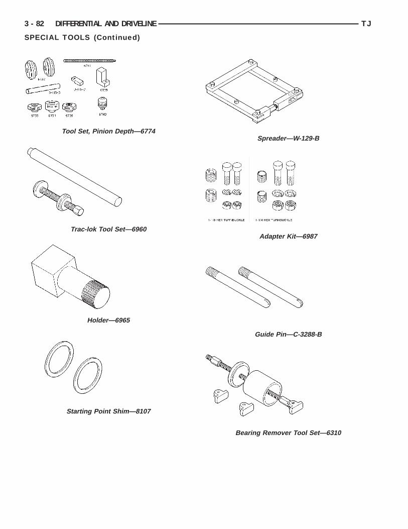
3 - 82 DIFFERENTIAL AND DRIVELINE TJ
SPECIAL TOOLS (Continued)
Tool Set, Pinion Depth—6774
Trac-lok Tool Set—6960
Holder—6965
Starting Point Shim—8107
Spreader—W-129-B
Adapter Kit—6987
Guide Pin—C-3288-B
Bearing Remover Tool Set—6310

TJ DIFFERENTIAL AND DRIVELINE 3 - 83
SPECIAL TOOLS (Continued)
Hub Puller—6790
Dial Indicator—C-3339
G
D
D
S
R
G
2
hath
to
se
ssp
e
hct
a
3 - 84 DIFFERENTIAL AND DRIVELINE TJ
216 RBI REAR AXLE
INDEX
page page
D
C
A
S
S
ENERAL INFORMATION216 RBI AXLE . . . . . . . . . . . . . . . . . . . . . . . . . . 84LUBRICANT SPECIFICATIONS . . . . . . . . . . . . . . 84ESCRIPTION AND OPERATIONSTANDARD DIFFERENTIAL . . . . . . . . . . . . . . . . 85TRAC-LOK OPERATION . . . . . . . . . . . . . . . . . . . 85IAGNOSIS AND TESTINGBEARING NOISE . . . . . . . . . . . . . . . . . . . . . . . . 86DRIVELINE SNAP . . . . . . . . . . . . . . . . . . . . . . . 87GEAR NOISE . . . . . . . . . . . . . . . . . . . . . . . . . . . 86GENERAL INFORMATION . . . . . . . . . . . . . . . . . 86LOW SPEED KNOCK . . . . . . . . . . . . . . . . . . . . . 87TRAC–LOK DIFFERENTIAL NOISE . . . . . . . . . . 87TRAC–LOK TEST . . . . . . . . . . . . . . . . . . . . . . . 87VIBRATION . . . . . . . . . . . . . . . . . . . . . . . . . . . . 87ERVICE PROCEDURESLUBRICANT CHANGE . . . . . . . . . . . . . . . . . . . . 90EMOVAL AND INSTALLATIONAXLE BEARING AND SEAL . . . . . . . . . . . . . . . . 93AXLE SHAFT . . . . . . . . . . . . . . . . . . . . . . . . . . . 92DIFFERENTIAL . . . . . . . . . . . . . . . . . . . . . . . . . 94DIFFERENTIAL SIDE BEARINGS . . . . . . . . . . . . 95
nd gear ratio listed on a tag. The tag is attached to
FINAL ASSEMBLY . . . . . . . . . . . . . . . . . . . . . . 100PINION GEAR . . . . . . . . . . . . . . . . . . . . . . . . . . 97PINION SHAFT SEAL . . . . . . . . . . . . . . . . . . . . . 91REAR AXLE . . . . . . . . . . . . . . . . . . . . . . . . . . . . 90RING GEAR . . . . . . . . . . . . . . . . . . . . . . . . . . . . 96ISASSEMBLY AND ASSEMBLYSTANDARD DIFFERENTIAL . . . . . . . . . . . . . . 101TRAC-LOK DIFFERENTIAL . . . . . . . . . . . . . . . . 101LEANING AND INSPECTIONAXLE COMPONENTS . . . . . . . . . . . . . . . . . . . . 105TRAC-LOK . . . . . . . . . . . . . . . . . . . . . . . . . . . . 106DJUSTMENTSDIFFERENTIAL BEARING PRELOAD AND
GEAR BACKLASH . . . . . . . . . . . . . . . . . . . . . 108GEAR CONTACT PATTERN ANALYSIS . . . . . . . 111PINION GEAR DEPTH . . . . . . . . . . . . . . . . . . . 106PECIFICATIONS216 RBI AXLE . . . . . . . . . . . . . . . . . . . . . . . . . . 113216 RBI TORQUE . . . . . . . . . . . . . . . . . . . . . . . 113PECIAL TOOLS216 RBI AXLE . . . . . . . . . . . . . . . . . . . . . . . . . . 113
ENERAL INFORMATION
16 RBI AXLEThe 216 Rear Beam-design Iron (RBI) axle housing
as an iron center casting (differential housing) withxle shaft tubes extending from either side. Theubes are pressed and welded into the differentialousing to form a one-piece axle housing.The integral type housing, hypoid gear design has
he center line of the pinion set below the center linef the ring gear.The axle has a vent hose to relieve internal pres-
ure caused by lubricant vaporization and internalxpansion.The axles are equipped with semi-floating axle
hafts. The vehicle weight is supported by the axlehaft and bearings. The axle shafts are retained bylates bolted to the end flanges of the axle tubes.The cover provides a means for servicing the differ-
ntial without removing the axle housing.For vehicles equipped with ABS brakes, the axles
ave a tone ring pressed onto the axle shaft. Useare when removing axle shafts to ensure that theone ring or the wheel speed sensor are not damaged.
The 216 RBI axle has the assembly part number
the differential housing by a cover bolt. Build dateidentification codes are stamped on the cover side ofan axle shaft tube.
The differential case is a one-piece design. The dif-ferential pinion mate shaft is retained with a roll-pin. Differential side bearing preload and ring gearbacklash is adjusted by shims positioned between theside bearing cone and differential case. Pinion geardepth is adjusted by shims positioned between theaxle housing and the inner pinion bearing cup. Pin-ion bearing preload is maintained by shims posi-tioned between the pinion gear shaft shoulder andthe outer bearing cone. (Fig. 1)
LUBRICANT SPECIFICATIONSA multi-purpose, hypoid gear lubricant which con-
forms to the following specifications should be used.Mopart Hypoid Gear Lubricant conforms to all ofthese specifications.
• The lubricant should have MIL–L–2105C andAPI GL 5 quality specifications.
• Lubricant is a thermally stable SAE 80W–90gear lubricant.

tl
oai
Cmp
D
S
br
smpa
r
p
t
iodgp
TJ DIFFERENTIAL AND DRIVELINE 3 - 85
GENERAL INFORMATION (Continued)
• Lubricant for axles intended for heavy-duty orrailer tow use is SAE 75W–140 SYNTHETIC gearubricant.
Trac-lok differentials require the addition of 4 oz.f friction modifier to the axle lubricant. The 216 RBIxle lubricant capacity is 1.89 L (4.0 pts.) total,ncluding the friction modifier if necessary.
AUTION: If axle is submerged in water, lubricantust be replaced immediately to avoid possibleremature axle failure.
ESCRIPTION AND OPERATION
TANDARD DIFFERENTIALThe differential gear system divides the torque
etween the axle shafts. It allows the axle shafts tootate at different speeds when turning corners.Each differential side gear is splined to an axle
haft. The pinion gears are mounted on a pinionate shaft and are free to rotate on the shaft. The
inion gear is fitted in a bore in the differential casend is positioned at a right angle to the axle shafts.In operation, power flow occurs as follows:• The pinion gear rotates the ring gear• The ring gear (bolted to the differential case)
otates the case• The differential pinion gears (mounted on the
inion mate shaft in the case) rotate the side gears• The side gears (splined to the axle shafts) rotate
he shaftsDuring straight-ahead driving, the differential pin-
on gears do not rotate on the pinion mate shaft. Thisccurs because input torque applied to the gears isivided and distributed equally between the two sideears. As a result, the pinion gears revolve with theinion mate shaft but do not rotate around it (Fig. 2).
Fig. 1 Axle Adjustment Shims
When turning corners, the outside wheel musttravel a greater distance than the inside wheel tocomplete a turn. The difference must be compensatedfor to prevent the tires from scuffing and skiddingthrough turns. To accomplish this, the differentialallows the axle shafts to turn at unequal speeds (Fig.3). In this instance, the input torque applied to thepinion gears is not divided equally. The pinion gearsnow rotate around the pinion mate shaft in oppositedirections. This allows the side gear and axle shaftattached to the outside wheel to rotate at a fasterspeed.
TRAC-LOK OPERATIONIn a conventional differential, if one wheel spins,
the opposite wheel will generate only as much torqueas the spinning wheel.
In the Trac-lok differential, part of the ring geartorque is transmitted through clutch packs whichcontain multiple discs. The clutches will have radialgrooves on the plates, and concentric grooves on thediscs or bonded fiber material that is smooth inappearance.
Fig. 2 Differential Operation—Straight Ahead Driving
Fig. 3 Differential Operation—On Turns

tfwfa
nawtTrwtwtt
D
G
b
3 - 86 DIFFERENTIAL AND DRIVELINE TJ
DESCRIPTION AND OPERATION (Continued)
In operation, the Trac-lok clutches are engaged bywo concurrent forces. The first being the preloadorce exerted through Belleville spring washersithin the clutch packs. The second is the separating
orces generated by the side gears as torque ispplied through the ring gear (Fig. 4).
The Trac-lok design provides the differential actioneeded for turning corners and for driving straighthead during periods of unequal traction. When oneheel looses traction, the clutch packs transfer addi-
ional torque to the wheel having the most traction.rac-lok differentials resist wheel spin on bumpyoads and provide more pulling power when oneheel looses traction. Pulling power is provided con-
inuously until both wheels loose traction. If bothheels slip due to unequal traction, Trac-lok opera-
ion is normal. In extreme cases of differences ofraction, the wheel with the least traction may spin.
IAGNOSIS AND TESTING
ENERAL INFORMATIONAxle bearing problem conditions are usually caused
y:• Insufficient or incorrect lubricant.• Foreign matter/water contamination.
Fig. 4 Trac-lok Limited Slip Differential Operation
• Incorrect bearing preload torque adjustment.• Incorrect backlash.Axle gear problem conditions are usually the result
of:• Insufficient lubrication.• Incorrect or contaminated lubricant.• Overloading (excessive engine torque) or exceed-
ing vehicle weight capacity.• Incorrect clearance or backlash adjustment.Axle component breakage is most often the result
of:• Severe overloading.• Insufficient lubricant.• Incorrect lubricant.• Improperly tightened components.
GEAR NOISEAxle gear noise can be caused by insufficient lubri-
cant, incorrect backlash, tooth contact, or worn/dam-aged gears.
Gear noise usually happens at a specific speedrange. The range is 30 to 40 mph, or above 50 mph.The noise can also occur during a specific type ofdriving condition. These conditions are acceleration,deceleration, coast, or constant load.
When road testing, accelerate the vehicle to thespeed range where the noise is the greatest. Shiftout-of-gear and coast through the peak–noise range.If the noise stops or changes greatly:
• Check for insufficient lubricant.• Incorrect ring gear backlash.• Gear damage.Differential side and pinion gears can be checked
by turning the vehicle. They usually do not causenoise during straight–ahead driving when the gearsare unloaded. The side gears are loaded during vehi-cle turns. A worn pinion gear mate shaft can alsocause a snapping or a knocking noise.
BEARING NOISEThe axle shaft, differential and pinion gear bear-
ings can all produce noise when worn or damaged.Bearing noise can be either a whining, or a growlingsound.
Pinion gear bearings have a constant–pitch noise.This noise changes only with vehicle speed. Pinionbearing noise will be higher because it rotates at afaster rate. Drive the vehicle and load the differen-tial. If bearing noise occurs, the rear pinion bearingis the source of the noise. If the bearing noise isheard during a coast, the front pinion bearing is thesource.
Worn or damaged differential bearings usually pro-duce a low pitch noise. Differential bearing noise issimilar to pinion bearing noise. The pitch of differen-

tw
wwTTli
L
Upk
V
c
ocve
b
v
D
i
mi
mvwc
TJ DIFFERENTIAL AND DRIVELINE 3 - 87
DIAGNOSIS AND TESTING (Continued)
ial bearing noise is also constant and varies onlyith vehicle speed.Axle shaft bearings produce noise and vibrationhen worn or damaged. The noise generally changeshen the bearings are loaded. Road test the vehicle.urn the vehicle sharply to the left and to the right.his will load the bearings and change the noise
evel. Where axle bearing damage is slight, the noises usually not noticeable at speeds above 30 mph.
OW SPEED KNOCKLow speed knock is generally caused by a worn–joint or by worn side–gear thrust washers. A worninion gear shaft bore will also cause low speednock.
IBRATIONVibration at the rear of the vehicle is usually
aused by a:• Damaged drive shaft.• Missing drive shaft balance weight(s).• Worn or out–of–balance wheels.• Loose wheel lug nuts.• Worn U–joint(s).• Loose/broken springs.• Damaged axle shaft bearing(s).• Loose pinion gear nut.• Excessive pinion yoke run out.• Bent axle shaft(s).Check for loose or damaged front–end components
r engine/transmission mounts. These componentsan contribute to what appears to be a rear–endibration. Do not overlook engine accessories, brack-ts and drive belts.All driveline components should be examined
efore starting any repair.Refer to Group 22, Wheels and Tires, for additional
ibration information.
RIVELINE SNAPA snap or clunk noise when the vehicle is shifted
nto gear (or the clutch engaged), can be caused by:• High engine idle speed• Loose engine/transmission/transfer case mounts• Worn U–joints• Loose spring mounts• Loose pinion gear nut and yoke• Excessive ring gear backlash• Excessive side gear/case clearance
The source of a snap or a clunk noise can be deter-mined with the assistance of a helper. Raise the vehi-cle on a hoist with the wheels free to rotate. Instructthe helper to shift the transmission into gear. Listenfor the noise, a mechanics stethoscope is helpful inisolating the source of a noise.
TRAC–LOK DIFFERENTIAL NOISEThe most common problem is a chatter noise when
turning corners. Before removing a Trac-lok unit forrepair, drain, flush and refill the axle with the spec-ified lubricant. Refer to Lubricant change in thisGroup.
A container of Mopart Trac-lok Lubricant (frictionodifier) should be added after repair service or dur-
ng a lubricant change.After changing the lubricant, drive the vehicle andake 10 to 12 slow, figure-eight turns. This maneu-
er will pump lubricant through the clutches. Thisill correct the condition in most instances. If the
hatter persists, clutch damage could have occurred.
TRAC–LOK TEST
WARNING: WHEN SERVICING VEHICLES WITH ATRAC–LOK DIFFERENTIAL DO NOT USE THEENGINE TO TURN THE AXLE AND WHEELS. BOTHREAR WHEELS MUST BE RAISED AND THE VEHI-CLE SUPPORTED. A TRAC–LOK AXLE CAN EXERTENOUGH FORCE IF ONE WHEEL IS IN CONTACTWITH A SURFACE TO CAUSE THE VEHICLE TOMOVE.
The differential can be tested without removing thedifferential case by measuring rotating torque. Makesure brakes are not dragging during this measure-ment.
(1) Place blocks in front and rear of both frontwheels.
(2) Raise one rear wheel until it is completely offthe ground.
(3) Engine off, transmission in neutral, and park-ing brake off.
(4) Remove wheel and bolt Special Tool 6790 tostuds.
(5) Use torque wrench on special tool to rotatewheel and read rotating torque (Fig. 5).
(6) If rotating torque is less than 22 N·m (30 ft.lbs.) or more than 271 N·m (200 ft. lbs.) on eitherwheel the unit should be serviced.

3 - 88 DIFFERENTIAL AND DRIVELINE TJ
DIAGNOSIS AND TESTING (Continued)
DIAGNOSIS CHART

TJ DIFFERENTIAL AND DRIVELINE 3 - 89
DIAGNOSIS AND TESTING (Continued)
DIAGNOSIS CHART — CONTINUED

S
L
d
d
ls
a
a
a
T
3 - 90 DIFFERENTIAL AND DRIVELINE TJ
DIAGNOSIS AND TESTING (Continued)
ERVICE PROCEDURES
UBRICANT CHANGE(1) Raise and support the vehicle.(2) Remove the lubricant fill hole plug from the
ifferential housing cover.(3) Remove the differential housing cover and
rain the lubricant from the housing.(4) Clean the housing cavity with a flushing oil,
ight engine oil, or lint free cloth. Do not use water,team, kerosene, or gasoline for cleaning.(5) Remove the original sealant from the housing
nd cover surfaces.(6) Apply a bead of Mopart Silicone Rubber Seal-
nt, or equivalent, to the housing cover (Fig. 6).
Install the housing cover within 5 minutesfter applying the sealant.(7) Install the cover and any identification tag.
ighten the cover bolts to 41 N·m (30 ft. lbs.) torque.
Fig. 5 Trac-lok Test —Typical
Fig. 6 Apply Sealant
(8) For Trac–lok differentials, a quantity ofMopart Trac–lok lubricant (friction modifier), orequivalent, must be added after repair service or alubricant change. Refer to the Lubricant Specifica-tions section of this group for the quantity necessary.
(9) Fill differential with Mopart Hypoid GearLubricant, or equivalent, to bottom of the fill plughole. Refer to the Lubricant Specifications section ofthis group for the quantity necessary.
CAUTION: Overfilling the differential can result inlubricant foaming and overheating.
(10) Install the fill hole plug and lower the vehicle.(11) Trac–lok differential equipped vehicles should
be road tested by making 10 to 12 slow figure-eightturns. This maneuver will pump the lubricantthrough the clutch discs to eliminate a possible chat-ter noise complaint.
REMOVAL AND INSTALLATION
REAR AXLE
REMOVAL(1) Raise and support the vehicle.(2) Position a suitable lifting device under the
axle.(3) Secure axle to device.(4) Remove the wheels and tires.(5) Remove the brake drums from the axle. Refer
to Group 5, Brakes, for proper procedures.(6) Disconnect parking brake cables from brackets
and lever.(7) Remove wheel speed sensors, if necessary.
Refer to Group 5, Brakes, for proper procedures.(8) Disconnect the brake hose at the axle junction
block. Do not disconnect the brake hydraulic lines atthe wheel cylinders. Refer to Group 5, Brakes, forproper procedures.
(9) Disconnect the vent hose from the axle shafttube.
(10) Mark the propeller shaft and yokes for instal-lation alignment reference.
(11) Remove propeller shaft.(12) Disconnect stabilizer bar links.(13) Disconnect shock absorbers from axle.(14) Disconnect track bar.(15) Disconnect upper and lower suspension arms
from the axle brackets.(16) Separate the axle from the vehicle.

I
Nptah
s
ot
t
N
5
R
l
B
bd
et
Lr
v
N
(
t
P
R
B
i
TJ DIFFERENTIAL AND DRIVELINE 3 - 91
REMOVAL AND INSTALLATION (Continued)
NSTALLATION
OTE: The weight of the vehicle must be sup-orted by the springs before suspension arms and
rack bar fasteners can be tightened. If the springsre not at their normal ride position, vehicle rideeight and handling could be affected.
(1) Raise the axle with lifting device and align coilprings.(2) Position the upper and lower suspension arms
n the axle brackets. Install nuts and bolts, do notighten bolts at this time.
(3) Install track bar and attachment bolts, do notighten bolts at this time.
(4) Install shock absorbers and tighten nuts to 100·m (74 ft. lbs.) torque.(5) Install stabilizer bar links and tighten nuts to
4 N·m (40 ft. lbs.) torque.(6) Install the wheel speed sensors, if necessary.efer to Group 5, Brakes, for proper procedures.(7) Connect parking brake cable to brackets and
ever.(8) Install the brake drums. Refer to Group 5,rakes, for proper procedures.(9) Connect the brake hose to the axle junction
lock. Refer to Group 5, Brakes, for proper proce-ures.(10) Install axle vent hose.(11) Align propeller shaft and pinion yoke refer-
nce marks. Install U-joint straps and bolts. Tighteno 19 N·m (14 ft. lbs.) torque.
(12) Install the wheels and tires.(13) Add gear lubricant, if necessary. Refer to
ubricant Specifications in this section for lubricantequirements.(14) Remove lifting device from axle and lower the
ehicle.(15) Tighten lower suspension arm bolts to 177·m (130 ft. lbs.) torque.(16) Tighten upper suspension arm bolts to 75 N·m
55 ft. lbs.) torque.(17) Tighten track bar bolts to 100 N·m (74 ft. lbs.)
orque.
INION SHAFT SEAL
EMOVAL(1) Raise and support the vehicle.(2) Remove wheel and tire assemblies.(3) Remove brake drums. Refer to Group 5,rakes, for proper procedures.(4) Mark the propeller shaft and pinion yoke for
nstallation reference.(5) Remove the propeller shaft from the yoke.(6) Rotate the pinion gear three or four times.
(7) Measure the amount of torque necessary torotate the pinion gear with a (in. lbs.) dial-typetorque wrench. Record the torque reading for instal-lation reference.
(8) Using Holder 6958 to hold the pinion yoke,remove the pinion nut and washer.
(9) Use Remover C-452 and Wrench C-3281 toremove the pinion yoke (Fig. 7).
(10) Use a suitable pry tool or a slide hammermounted screw to remove the pinion shaft seal.
INSTALLATION(1) Apply a light coating of gear lubricant on the
lip of pinion seal. Install seal with Installer C-3972-Aand Handle C-4171 (Fig. 8).
(2) Install yoke on the pinion gear with InstallerW-162–D, Cup 8109, and Holder 6958 (Fig. 9).
Fig. 7 Pinion Yoke Removal
Fig. 8 Pinion Seal Installation

Ctar
pr
wiN
h
3 - 92 DIFFERENTIAL AND DRIVELINE TJ
REMOVAL AND INSTALLATION (Continued)
AUTION: Do not exceed the minimum tighteningorque when installing the pinion yoke retaining nutt this point. Damage to the pinion bearings mayesult.
(3) Install the pinion washer and a new nut on theinion gear. Tighten the nut only enough toemove the shaft end play.(4) Tighten pinion nut to 217 N·m (160 ft. lbs.).(5) Rotate the pinion shaft using a (in. lbs.) torquerench. Rotating torque should be equal to the read-
ng recorded during removal, plus an additional 0.56·m (5 in. lbs.) (Fig. 10).
(6) If the rotating torque is low, use Holder 6958 toold the pinion yoke, and tighten the pinion shaft
Fig. 9 Pinion Yoke Installation
Fig. 10 Check Pinion Rotation Torque
nut in 6.8 N·m (5 ft. lbs.) increments until properrotating torque is achieved.
(7) Align the installation reference marks on thepropeller shaft and yoke, and install the propellershaft.
(8) Check and fill the gear lubricant. Refer to theLubricant Specifications for gear lubricant require-ments.
(9) Install the brake drums. Refer to Group 5,Brakes, for proper procedures.
(10) Install wheel and tire assemblies.(11) Lower the vehicle.
AXLE SHAFT
REMOVAL(1) Hoist and support vehicle on safety stands.(2) Remove wheel from vehicle.(3) Remove brake drum. Refer to Group 5, Brakes,
for proper procedure.(4) Through access hole in axle flange, remove
nuts holding axle retainer plate to axle tube.(5) Using Slide Hammer 7420, Adapter 6790, and
suitable lug nuts, pull axle shaft from vehicle (Fig.11).
INSTALLATION
WARNING: Do not reuse the bolts and nuts thatretained the axle shaft to axle tube flange. Usedprevailing torque nuts can loosen, causing a dan-gerous condition.
(1) Insert axle into opening at end of axle tube.(2) Align flat area on axle shaft retaining plate
upward.(3) Insert the retaining bolts into the axle tube
flange and through the holes in the brake backingand axle shaft retaining plates.
Fig. 11 Axle Shaft, Remove

t
n
Lm
A
R
ip
a
ab
TJ DIFFERENTIAL AND DRIVELINE 3 - 93
REMOVAL AND INSTALLATION (Continued)
(4) Install nuts to hold axle retaining plate to axleube.
(5) Through access hole in axle flange, tightenuts to 61 N·m (45 ft. lbs.).(6) Install brake drum.(7) Install wheel and tire assembly.(8) Check and fill the gear lubricant. Refer to the
ubricant Specifications for gear lubricant require-ents.(9) Lower vehicle and road test to verify repair.
XLE BEARING AND SEAL
EMOVAL(1) Remove axle shaft from vehicle.(2) Using a 3/8 in. dia. drill bit, drill a shallow hole
nto soft steel axle bearing retaining ring (Fig. 12). Ifossible, use a drill depth stop to avoid marking axle.
(3) Using a suitable cold chisel, cut retaining ringcross drilled hole (Fig. 13).(4) Slide retaining ring from axle shaft.(5) Using Splitter 1130 placed between the seal
nd bearing and a suitable Arbor Press, press unitearing from axle shaft (Fig. 14).(6) Slide seal from axle.(7) Slide retaining plate from axle shaft.
Fig. 12 Drill Retaining Ring
INSTALLATION(1) Using a suitable straight edge, verify flatness
of axle shaft retaining plate. Replace plate if warped.(2) Install retaining plate on axle (Fig. 15).(3) Apply a coat of multi-purpose grease on sealing
surface of axle seal.(4) Install seal on axle with cavity away from
retaining plate (Fig. 15).(5) Lubricate bearing with Mopart Wheel Bearing
Grease, or equivalent. Wipe excess grease from out-side of bearing.
(6) Slide bearing onto axle shaft with groove inouter surface toward seal (Fig. 15).
(7) Using Installer 7913 and shop press, pressbearing onto axle shaft (Fig. 16).
(8) Using Installer 7913 and shop press, press softmetal retaining ring onto axle shaft (Fig. 17).
(9) Install axle in vehicle.
Fig. 13 Cut Retaining Ring
Fig. 14 Axle Bearing and Seal Remove
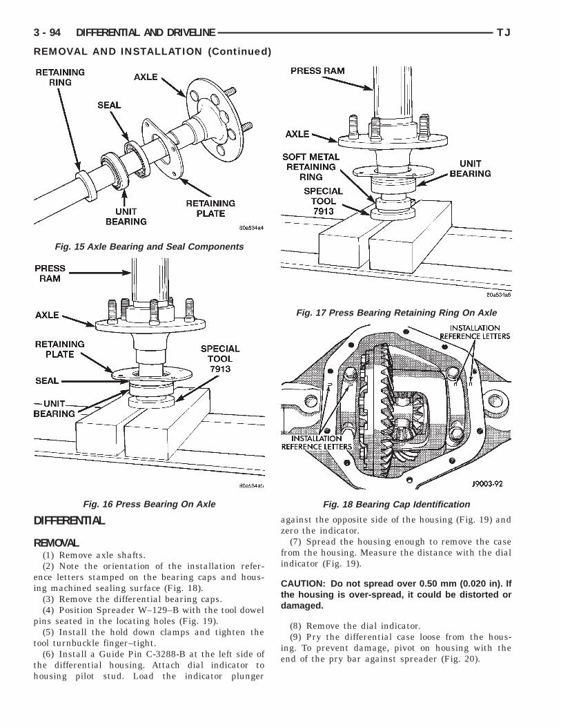
D
R
ei
p
t
th
3 - 94 DIFFERENTIAL AND DRIVELINE TJ
REMOVAL AND INSTALLATION (Continued)
IFFERENTIAL
EMOVAL(1) Remove axle shafts.(2) Note the orientation of the installation refer-
nce letters stamped on the bearing caps and hous-ng machined sealing surface (Fig. 18).
(3) Remove the differential bearing caps.(4) Position Spreader W–129–B with the tool dowel
ins seated in the locating holes (Fig. 19).(5) Install the hold down clamps and tighten the
ool turnbuckle finger–tight.(6) Install a Guide Pin C-3288-B at the left side of
he differential housing. Attach dial indicator toousing pilot stud. Load the indicator plunger
Fig. 15 Axle Bearing and Seal Components
Fig. 16 Press Bearing On Axle
against the opposite side of the housing (Fig. 19) andzero the indicator.
(7) Spread the housing enough to remove the casefrom the housing. Measure the distance with the dialindicator (Fig. 19).
CAUTION: Do not spread over 0.50 mm (0.020 in). Ifthe housing is over-spread, it could be distorted ordamaged.
(8) Remove the dial indicator.(9) Pry the differential case loose from the hous-
ing. To prevent damage, pivot on housing with theend of the pry bar against spreader (Fig. 20).
Fig. 17 Press Bearing Retaining Ring On Axle
Fig. 18 Bearing Cap Identification

br
I
phf
th
TJ DIFFERENTIAL AND DRIVELINE 3 - 95
REMOVAL AND INSTALLATION (Continued)
(10) Remove the case from housing. Mark or tagearing cups to indicate which side they wereemoved from.
NSTALLATION(1) Position Spreader W–129–B with the tool dowel
ins seated in the locating holes (Fig. 19). Install theold down clamps and tighten the tool turnbuckleinger–tight.
(2) Install a Guide Pin C-3288-B at the left side ofhe differential housing. Attach dial indicator toousing pilot stud. Load the indicator plunger
Fig. 19 Spread Differential Housing
Fig. 20 Differential Removal
against the opposite side of the housing (Fig. 19) andzero the indicator.
(3) Spread the housing enough to install the casein the housing. Measure the distance with the dialindicator (Fig. 19).
CAUTION: Do not spread over 0.50 mm (0.020 in). Ifthe housing is over-spread, it could be distorted ordamaged.
(4) Remove the dial indicator.(5) Install differential in housing.(6) Install case in the housing. Tap the differential
case with a rawhide or rubber mallet to ensure thebearings are fully seated in the differential housing(Fig. 21).
(7) Remove the spreader.
(8) Install the bearing caps at their original loca-tions (Fig. 22). Tighten the bearing cap bolts to 109N·m (80 ft. lbs.) torque.
(9) Install axle shafts.
DIFFERENTIAL SIDE BEARINGS
REMOVAL(1) Remove differential case from axle housing.(2) Remove the bearings from the differential case
with Puller/Press C-293-PA, Adapters C-293-18, andAdapter C-293-3 (Fig. 23).
(3) Remove differential preload shims from differ-ential case hubs. Tag the shims to identify which sideof the differential they came from.
Fig. 21 Differential Installation

I
dl
c
d
3 - 96 DIFFERENTIAL AND DRIVELINE TJ
REMOVAL AND INSTALLATION (Continued)
NSTALLATIONIf ring and pinion gears have been replaced, verify
ifferential side bearing preload and gear mesh back-ash.
(1) Install differential preload shims on differentialase hubs.(2) Using tool D-156 with handle C-4171, install
ifferential side bearings (Fig. 24).(3) Install differential in axle housing.
Fig. 22 Differential Bearing Cap Reference Letters
Fig. 23 Differential Bearing Removal
RING GEARThe ring and pinion gears are service in a matched
set. Do not replace the ring gear without replacingthe pinion gear.
REMOVAL(1) Remove differential from axle housing.(2) Place differential case in a suitable vise with
soft metal jaw protectors. (Fig. 25)(3) Remove bolts holding ring gear to differential
case.(4) Using a soft hammer, drive ring gear from dif-
ferential case (Fig. 25).
Fig. 24 Install Differential Side Bearings
Fig. 25 Ring Gear Removal
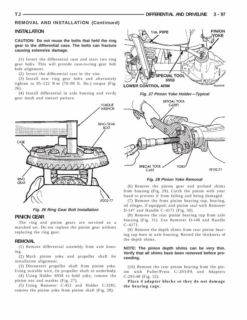
I
Cgc
gh
t2
g
P
mr
R
i
i
U
p
r
TJ DIFFERENTIAL AND DRIVELINE 3 - 97
REMOVAL AND INSTALLATION (Continued)
NSTALLATION
AUTION: Do not reuse the bolts that held the ringear to the differential case. The bolts can fractureausing extensive damage.
(1) Invert the differential case and start two ringear bolts. This will provide case-to-ring gear boltole alignment.(2) Invert the differential case in the vise.(3) Install new ring gear bolts and alternately
ighten to 95–122 N·m (70–90 ft. lbs.) torque (Fig.6).(4) Install differential in axle housing and verify
ear mesh and contact pattern.
INION GEARThe ring and pinion gears are serviced as aatched set. Do not replace the pinion gear without
eplacing the ring gear.
EMOVAL(1) Remove differential assembly from axle hous-
ng.(2) Mark pinion yoke and propeller shaft for
nstallation alignment.(3) Disconnect propeller shaft from pinion yoke.sing suitable wire, tie propeller shaft to underbody.(4) Using Holder 6958 to hold yoke, remove the
inion nut and washer (Fig. 27).(5) Using Remover C-452 and Holder C-3281,
emove the pinion yoke from pinion shaft (Fig. 28).
Fig. 26 Ring Gear Bolt Installation
(6) Remove the pinion gear and preload shimsfrom housing (Fig. 29). Catch the pinion with yourhand to prevent it from falling and being damaged.
(7) Remove the front pinion bearing cup, bearing,oil slinger, if equipped, and pinion seal with RemoverD-147 and Handle C–4171 (Fig. 30).
(8) Remove the rear pinion bearing cup from axlehousing (Fig. 31). Use Remover D-148 and HandleC–4171.
(9) Remove the depth shims from rear pinion bear-ing cup bore in axle housing. Record the thickness ofthe depth shims.
NOTE: The pinion depth shims can be very thin.Verify that all shims have been removed before pro-ceeding.
(10) Remove the rear pinion bearing from the pin-ion with Puller/Press C–293-PA and AdaptersC-293-48 (Fig. 32).
Place 4 adapter blocks so they do not damagethe bearing cage.
Fig. 27 Pinion Yoke Holder—Typical
Fig. 28 Pinion Yoke Removal

I
NrpiiRt
3 - 98 DIFFERENTIAL AND DRIVELINE TJ
REMOVAL AND INSTALLATION (Continued)
NSTALLATION
OTE: Pinion depth shims are placed between theear pinion bearing cup and axle housing to achieveroper ring and pinion gear mesh. If the factory
nstalled ring and pinion gears are reused, the pin-on depth shim should not require replacement.efer to Pinion Gear Depth to select the proper
hickness shim before installing pinion gear.
Fig. 29 Remove Pinion Gear
Fig. 30 Front Bearing Cup Removal
(1) Place proper thickness depth shim in rear pin-ion bearing cup bore in the axle housing.(2) Apply Mopart Door Ease, or equivalent, sticklubricant to outside surface of rear pinion bearingcup. Install the bearing cup with Installer D-145 andHandle C–4171 (Fig. 33). Verify cup is correctlyseated.
(3) Apply Mopart Door Ease, or equivalent, sticklubricant to outside surface of front pinion bearingcup. Install the bearing cup with Installer D-144 andHandle C–4171 (Fig. 34).
Fig. 31 Rear Bearing Cup Removal
Fig. 32 Inner Bearing Removal

e
la
ia
p
a
tl
TJ DIFFERENTIAL AND DRIVELINE 3 - 99
REMOVAL AND INSTALLATION (Continued)
(4) Install front pinion bearing, and oil slinger, ifquipped.(5) Apply a light coating of gear lubricant on the
ip of pinion seal. Install seal with Installer C-3972-And Handle C–4171 (Fig. 35).(6) Install the rear pinion bearing and oil slinger,
f equipped, on the pinion gear with Installer W-262nd a shop press (Fig. 36).(7) Install pinion bearing preload shims onto the
inion gear (Fig. 37).(8) Install pinion gear in housing.(9) Install yoke with Installer W-162-B, Cup 8109,
nd Holder 6958 (Fig. 38).(10) Install the pinion washer and a new nut on
he pinion gear. Tighten the nut to 217 N·m (160 ft.bs.) (Fig. 39).
Fig. 33 Rear Pinion Bearing Cup Installation
Fig. 34 Pinion Outer Bearing Cup Installation
CAUTION: Never loosen pinion gear nut todecrease pinion gear bearing rotating torque andnever exceed specified preload rotating torque.
(11) Check bearing preload torque with an inchpound torque wrench (Fig. 40). The torque necessaryto rotate the pinion gear should be:
• Original Bearings—1 to 3 N·m (10 to 20 in. lbs.).• New Bearings—2 to 5 N·m (15 to 35 in. lbs.).(12) If rotating torque is above the desired
amount, remove the pinion yoke and increase thepreload shim pack thickness. Increasing the shimpack thickness 0.025 mm (0.001 in.) will decrease therotating torque approximately 0.9 N·m (8 in. lbs.).
Fig. 35 Pinion Seal Installation
Fig. 36 Rear Pinion Bearing Installation
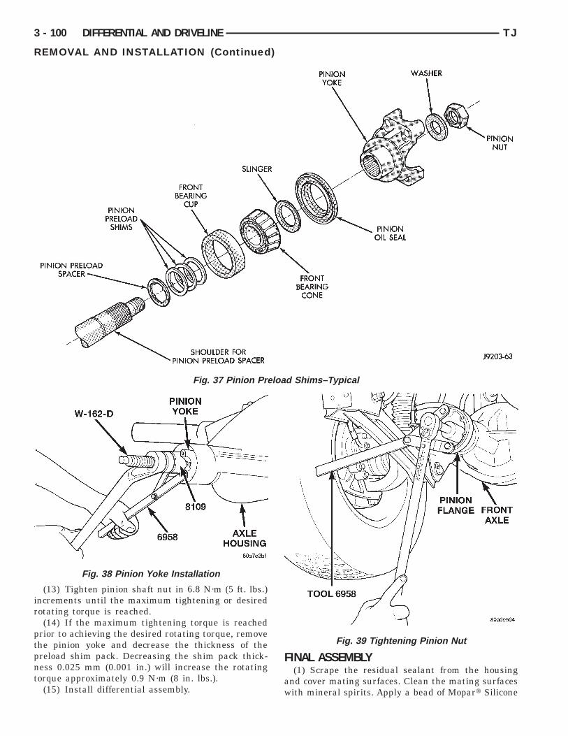
ir
ptpnt
load
3 - 100 DIFFERENTIAL AND DRIVELINE TJ
REMOVAL AND INSTALLATION (Continued)
(13) Tighten pinion shaft nut in 6.8 N·m (5 ft. lbs.)ncrements until the maximum tightening or desiredotating torque is reached.(14) If the maximum tightening torque is reached
rior to achieving the desired rotating torque, removehe pinion yoke and decrease the thickness of thereload shim pack. Decreasing the shim pack thick-ess 0.025 mm (0.001 in.) will increase the rotatingorque approximately 0.9 N·m (8 in. lbs.).
(15) Install differential assembly.
Fig. 37 Pinion Pre
Fig. 38 Pinion Yoke Installation
FINAL ASSEMBLY(1) Scrape the residual sealant from the housing
and cover mating surfaces. Clean the mating surfaceswith mineral spirits. Apply a bead of Mopart Silicone
Shims–Typical
Fig. 39 Tightening Pinion Nut
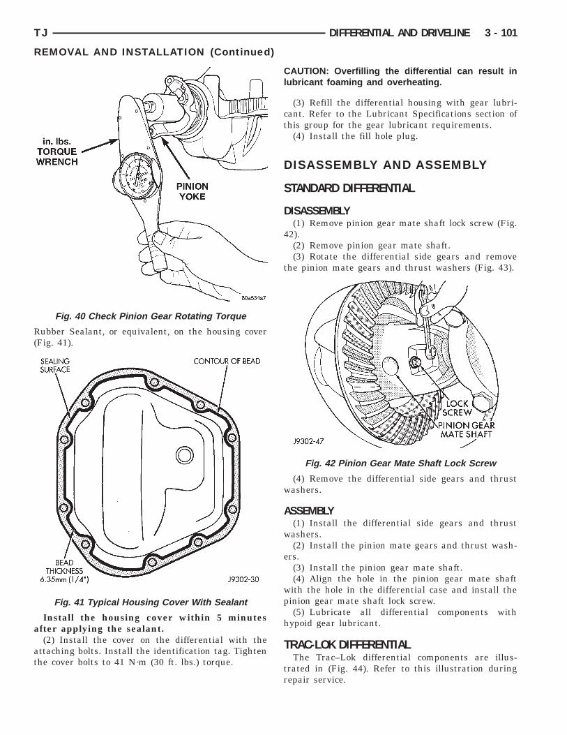
R(
a
at
TJ DIFFERENTIAL AND DRIVELINE 3 - 101
REMOVAL AND INSTALLATION (Continued)
ubber Sealant, or equivalent, on the housing coverFig. 41).
Install the housing cover within 5 minutesfter applying the sealant.(2) Install the cover on the differential with the
ttaching bolts. Install the identification tag. Tightenhe cover bolts to 41 N·m (30 ft. lbs.) torque.
Fig. 40 Check Pinion Gear Rotating Torque
Fig. 41 Typical Housing Cover With Sealant
CAUTION: Overfilling the differential can result inlubricant foaming and overheating.
(3) Refill the differential housing with gear lubri-cant. Refer to the Lubricant Specifications section ofthis group for the gear lubricant requirements.
(4) Install the fill hole plug.
DISASSEMBLY AND ASSEMBLY
STANDARD DIFFERENTIAL
DISASSEMBLY(1) Remove pinion gear mate shaft lock screw (Fig.
42).(2) Remove pinion gear mate shaft.(3) Rotate the differential side gears and remove
the pinion mate gears and thrust washers (Fig. 43).
(4) Remove the differential side gears and thrustwashers.
ASSEMBLY(1) Install the differential side gears and thrust
washers.(2) Install the pinion mate gears and thrust wash-
ers.(3) Install the pinion gear mate shaft.(4) Align the hole in the pinion gear mate shaft
with the hole in the differential case and install thepinion gear mate shaft lock screw.
(5) Lubricate all differential components withhypoid gear lubricant.
TRAC-LOK DIFFERENTIALThe Trac–Lok differential components are illus-
trated in (Fig. 44). Refer to this illustration duringrepair service.
Fig. 42 Pinion Gear Mate Shaft Lock Screw

D
v
H
3 - 102 DIFFERENTIAL AND DRIVELINE TJ
DISASSEMBLY AND ASSEMBLY (Continued)
ISASSEMBLY(1) Clamp Side Gear Holding Tool 6963–A in a
ise.(2) Position the differential case on Side Gearolding Tool 6963-A (Fig. 45).
Fig. 43 Pinion Mate Gear Removal
Fig. 44 Trac–Lok Dif
(3) Remove ring gear, if necessary. Ring gearremoval is necessary only if the ring gear is to bereplaced. The Trac-Lok differential can be servicedwith the ring gear installed.
(4) Remove the pinion gear mate shaft lock screw(Fig. 46).
tial Components
Fig. 45 Differential Case Holding Tool
feren

s
4
sa
Ta
(p
r(
5
i
TJ DIFFERENTIAL AND DRIVELINE 3 - 103
DISASSEMBLY AND ASSEMBLY (Continued)
(5) Remove the pinion gear mate shaft. If neces-ary, use a drift and hammer (Fig. 47).
(6) Install and lubricate Step Plate C–4487–1 (Fig.8).(7) Assemble Threaded Adapter C–4487–3 into top
ide gear. Thread Forcing Screw C–4487–2 intodapter until it becomes centered in adapter plate.(8) Position a small screw driver in slot of
hreaded Adapter C–4487–3 (Fig. 49) to preventdapter from turning.(9) Tighten forcing screw tool 122 N·m (90 ft. lbs.)
maximum) to compress Belleville springs in clutchacks (Fig. 50).(10) Using an appropriate size feeler gauge,
emove thrust washers from behind the pinion gearsFig. 51).
(11) Insert Turning Bar C–4487–4 in case (Fig.2).(12) Loosen the Forcing Screw C-4487-2 in small
ncrements until the clutch pack tension is relieved
Fig. 46 Mate Shaft Lock Screw
Fig. 47 Mate Shaft Removal
and the differential case can be turned using TurningBar C-4487-4.
(13) Rotate differential case until the pinion gearscan be removed.
(14) Remove pinion gears from differential case.(15) Remove Forcing Screw C–4487-2, Step Plate
C-4487-1, and Threaded Adapter C-4487-3.(16) Remove top side gear, clutch pack retainer,
and clutch pack. Keep plates in correct order duringremoval (Fig. 53).
Fig. 48 Step Plate Tool Installation
Fig. 49 Threaded Adapter Installation
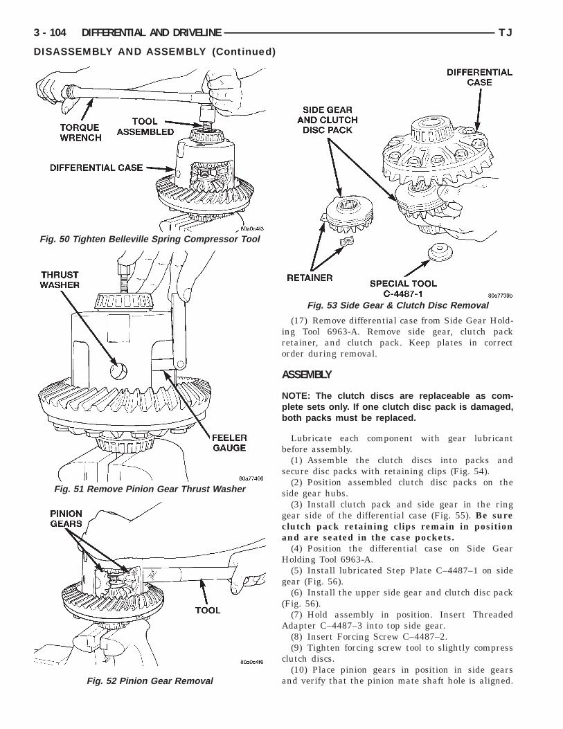
ca
H
g
(
A
c
a
Fig. 50 Tighten Belleville Spring Compressor Tool
Fig. 52 Pinion Gear Removal
3 - 104 DIFFERENTIAL AND DRIVELINE TJ
DISASSEMBLY AND ASSEMBLY (Continued)
(17) Remove differential case from Side Gear Hold-ing Tool 6963-A. Remove side gear, clutch packretainer, and clutch pack. Keep plates in correctorder during removal.
ASSEMBLY
NOTE: The clutch discs are replaceable as com-plete sets only. If one clutch disc pack is damaged,both packs must be replaced.
Lubricate each component with gear lubricantbefore assembly.
(1) Assemble the clutch discs into packs andsecure disc packs with retaining clips (Fig. 54).
(2) Position assembled clutch disc packs on theside gear hubs.
(3) Install clutch pack and side gear in the ringgear side of the differential case (Fig. 55). Be surelutch pack retaining clips remain in positionnd are seated in the case pockets.(4) Position the differential case on Side Gearolding Tool 6963-A.(5) Install lubricated Step Plate C–4487–1 on side
ear (Fig. 56).(6) Install the upper side gear and clutch disc pack
Fig. 56).(7) Hold assembly in position. Insert Threaded
dapter C–4487–3 into top side gear.(8) Insert Forcing Screw C–4487–2.(9) Tighten forcing screw tool to slightly compress
lutch discs.(10) Place pinion gears in position in side gears
nd verify that the pinion mate shaft hole is aligned.
Fig. 53 Side Gear & Clutch Disc Removal
Fig. 51 Remove Pinion Gear Thrust Washer

twti
t
pdi
TJ DIFFERENTIAL AND DRIVELINE 3 - 105
DISASSEMBLY AND ASSEMBLY (Continued)
(11) Rotate case with Turning Bar C–4487–4 untilhe pinion mate shaft holes in pinion gears alignith holes in case. It may be necessary to slightly
ighten the forcing screw in order to install the pin-on gears.
(12) Tighten forcing screw to 122 N·m (90 ft. lbs.)o compress the Belleville springs.
(13) Lubricate and install thrust washers behindinion gears and align washers with a small screwriver. Insert mate shaft into each pinion gear to ver-fy alignment.
Fig. 54 Clutch Disc Pack
Fig. 55 Clutch Discs & Lower Side Gear Installation
(14) Remove forcing screw, threaded adapter, andstep plate.
(15) Install pinion gear mate shaft and align holesin shaft and case.
(16) Install the pinion mate shaft lock screw fingertight to hold shaft during differential installation.
If replacement side and/or pinion gears andthrust washers were installed, it is not neces-sary to measure the side gear backlash. Correctfit is due to close machining tolerances duringmanufacture.
(17) Lubricate all differential components withhypoid gear lubricant.
CLEANING AND INSPECTION
AXLE COMPONENTSWash differential components with cleaning solvent
and dry with compressed air. Do not steam cleanthe differential components.
Wash bearings with solvent and towel dry, or drywith compressed air. DO NOT spin bearings withcompressed air. Cup and bearing must bereplaced as matched sets only.
Clean axle shaft tubes and oil channels in housing.Inspect for;• Smooth appearance with no broken/dented sur-
faces on the bearing rollers or the roller contact sur-faces.
• Bearing cups must not be distorted or cracked.• Machined surfaces should be smooth and with-
out any raised edges.• Raised metal on shoulders of cup bores should
be removed with a hand stone.
Fig. 56 Upper Side Gear & Clutch Disc PackInstallation

pa
t
a
aR
n
T
ppcdgIw
P
lam
A
P
G
sp5ibdptppBt
aui
vmt
3 - 106 DIFFERENTIAL AND DRIVELINE TJ
CLEANING AND INSPECTION (Continued)
• Wear and damage to pinion gear mate shaft,inion gears, side gears and thrust washers. Replaces a matched set only.• Ring and pinion gear for worn and chipped
eeth.• Ring gear for damaged bolt threads. Replaced asmatched set only.• Pinion yoke for cracks, worn splines, pitted
reas, and a rough/corroded seal contact surface.epair or replace as necessary.• Preload shims for damage and distortion. Install
ew shims, if necessary.
RAC-LOKClean all components in cleaning solvent. Dry com-
onents with compressed air. Inspect clutch packlates for wear, scoring or damage. Replace bothlutch packs if any one component in either pack isamaged. Inspect side and pinion gears. Replace anyear that is worn, cracked, chipped or damaged.nspect differential case and pinion shaft. Replace iforn or damaged.
RESOAK PLATES AND DISCPlates and discs with fiber coating (no grooves or
ines) must be presoaked in Friction Modifier beforessembly. Soak plates and discs for a minimum of 20inutes.
DJUSTMENTS
INION GEAR DEPTH
ENERAL INFORMATIONRing and pinion gears are supplied as matched
ets only. The identifying numbers for the ring andinion gear are etched into the face of each gear (Fig.7). A plus (+) number, minus (–) number or zero (0)s etched into the face of the pinion gear. This num-er is the amount (in thousandths of an inch) theepth varies from the standard depth setting of ainion etched with a (0). The standard setting fromhe center line of the ring gear to the back face of theinion is 109.52 mm (4.312 in.). The standard depthrovides the best teeth contact pattern. Refer toacklash and Contact Pattern Analysis Paragraph in
his section for additional information.Compensation for pinion depth variance is
chieved with select shims. The shims are placednder the inner pinion bearing cup in the axle hous-
ng bore (Fig. 58).If a new gear set is being installed, note the depth
ariance etched into both the original and replace-ent pinion gear. Add or subtract the thickness of
he original depth shims to compensate for the differ-
ence in the depth variances. Refer to the Depth Vari-ance charts.
Note where Old and New Pinion Marking columnsintersect. The intersecting figure represents plus orminus the amount needed.
Note the etched number on the face of the drivepinion gear (–1, –2, 0, +1, +2, etc.). The numbers rep-resent thousands of an inch deviation from the stan-dard. If the number is negative, add that value to therequired thickness of the depth shim(s). If the num-ber is positive, subtract that value from the thicknessof the depth shim(s). If the number is 0 no change isnecessary. Refer to the Pinion Gear Depth VarianceChart.
Fig. 57 Pinion Gear ID Numbers
Fig. 58 Shim Locations
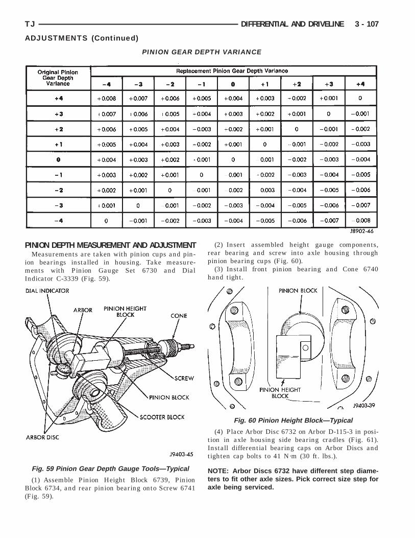
P
imI
B(
TJ DIFFERENTIAL AND DRIVELINE 3 - 107
ADJUSTMENTS (Continued)
INION DEPTH MEASUREMENT AND ADJUSTMENTMeasurements are taken with pinion cups and pin-
on bearings installed in housing. Take measure-ents with Pinion Gauge Set 6730 and Dial
ndicator C-3339 (Fig. 59).
(1) Assemble Pinion Height Block 6739, Pinionlock 6734, and rear pinion bearing onto Screw 6741
Fig. 59).
PINION GEAR D
Fig. 59 Pinion Gear Depth Gauge Tools—Typical
(2) Insert assembled height gauge components,rear bearing and screw into axle housing throughpinion bearing cups (Fig. 60).
(3) Install front pinion bearing and Cone 6740hand tight.
(4) Place Arbor Disc 6732 on Arbor D-115-3 in posi-tion in axle housing side bearing cradles (Fig. 61).Install differential bearing caps on Arbor Discs andtighten cap bolts to 41 N·m (30 ft. lbs.).
NOTE: Arbor Discs 6732 have different step diame-ters to fit other axle sizes. Pick correct size step foraxle being serviced.
TH VARIANCE
Fig. 60 Pinion Height Block—Typical
EP
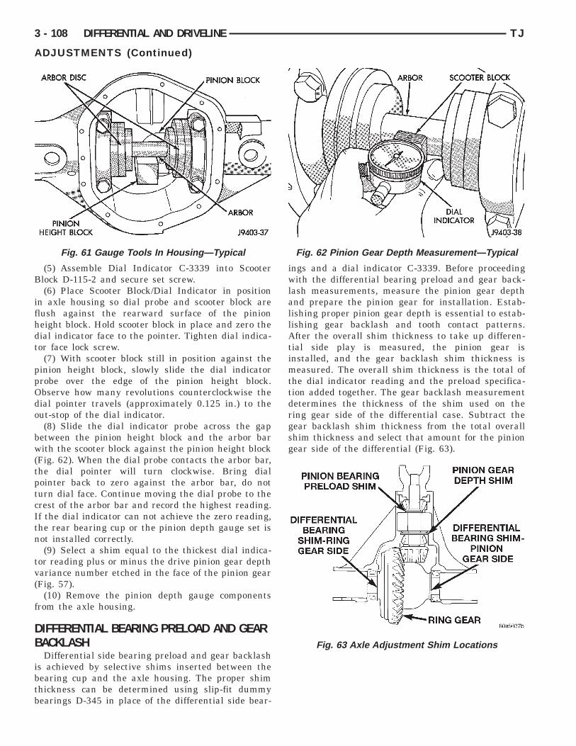
B
ifhdt
ppOdo
bw(tptcItn
tv(
f
DB
ibtb
3 - 108 DIFFERENTIAL AND DRIVELINE TJ
ADJUSTMENTS (Continued)
(5) Assemble Dial Indicator C-3339 into Scooterlock D-115-2 and secure set screw.(6) Place Scooter Block/Dial Indicator in position
n axle housing so dial probe and scooter block arelush against the rearward surface of the pinioneight block. Hold scooter block in place and zero theial indicator face to the pointer. Tighten dial indica-or face lock screw.
(7) With scooter block still in position against theinion height block, slowly slide the dial indicatorrobe over the edge of the pinion height block.bserve how many revolutions counterclockwise theial pointer travels (approximately 0.125 in.) to theut-stop of the dial indicator.(8) Slide the dial indicator probe across the gap
etween the pinion height block and the arbor barith the scooter block against the pinion height block
Fig. 62). When the dial probe contacts the arbor bar,he dial pointer will turn clockwise. Bring dialointer back to zero against the arbor bar, do noturn dial face. Continue moving the dial probe to therest of the arbor bar and record the highest reading.f the dial indicator can not achieve the zero reading,he rear bearing cup or the pinion depth gauge set isot installed correctly.(9) Select a shim equal to the thickest dial indica-
or reading plus or minus the drive pinion gear depthariance number etched in the face of the pinion gearFig. 57).
(10) Remove the pinion depth gauge componentsrom the axle housing.
IFFERENTIAL BEARING PRELOAD AND GEARACKLASHDifferential side bearing preload and gear backlash
s achieved by selective shims inserted between theearing cup and the axle housing. The proper shimhickness can be determined using slip-fit dummyearings D-345 in place of the differential side bear-
Fig. 61 Gauge Tools In Housing—Typical
ings and a dial indicator C-3339. Before proceedingwith the differential bearing preload and gear back-lash measurements, measure the pinion gear depthand prepare the pinion gear for installation. Estab-lishing proper pinion gear depth is essential to estab-lishing gear backlash and tooth contact patterns.After the overall shim thickness to take up differen-tial side play is measured, the pinion gear isinstalled, and the gear backlash shim thickness ismeasured. The overall shim thickness is the total ofthe dial indicator reading and the preload specifica-tion added together. The gear backlash measurementdetermines the thickness of the shim used on thering gear side of the differential case. Subtract thegear backlash shim thickness from the total overallshim thickness and select that amount for the piniongear side of the differential (Fig. 63).
Fig. 62 Pinion Gear Depth Measurement—Typical
Fig. 63 Axle Adjustment Shim Locations

DS
Nbr
e
t
t
t
6
p
ei
TJ DIFFERENTIAL AND DRIVELINE 3 - 109
ADJUSTMENTS (Continued)
IFFERENTIAL PRELOAD AND GEAR BACHLASHHIM SELECTION
OTE: It is difficult to salvage the differential sideearings during the removal procedure. Installeplacement bearings if necessary.
(1) Remove differential side bearings from differ-ntial case.(2) Remove factory installed shims from differen-
ial case.(3) Install ring gear on differential case and
ighten bolts to specification.(4) Install dummy side bearings D-345 on differen-
ial case.(5) Install differential case in axle housing (Fig.
4).(6) Install the marked bearing caps in their correct
ositions. Install and snug the bolts (Fig. 65).
(7) Using a dead-blow type mallet, seat the differ-ntial dummy bearings to each side of the axle hous-ng (Fig. 66) and (Fig. 67).
Fig. 64 Install Differential Case W/Dummy Bearings
Fig. 65 Tighten Bolts Holding Bearing Caps
(8) Thread guide stud C-3288-B into rear coverbolt hole below ring gear (Fig. 68).
(9) Attach a dial indicator C-3339 to Guide StudC-3288-B. Position the dial indicator plunger on aflat surface between the ring gear bolt heads (Fig.68).
(10) Push and hold differential case to pinion gearside of axle housing (Fig. 69).
(11) Zero dial indicator face to pointer (Fig. 69).(12) Push and hold differential case to ring gear
side of the axle housing (Fig. 70).(13) Record dial indicator reading (Fig. 70).(14) Add the dial indicator reading to the starting
point shim thickness to determine total shim thick-ness to achieve zero differential end play.
(15) Add 0.008 in. (0.2 mm) to the zero end playtotal. This new total represents the thickness ofshims to compress, or preload the new bearings whenthe differential is installed.
Fig. 66 Seat Pinion Gear Side Differential DummyBearing
Fig. 67 Seat Ring Gear Side Differential DummyBearing
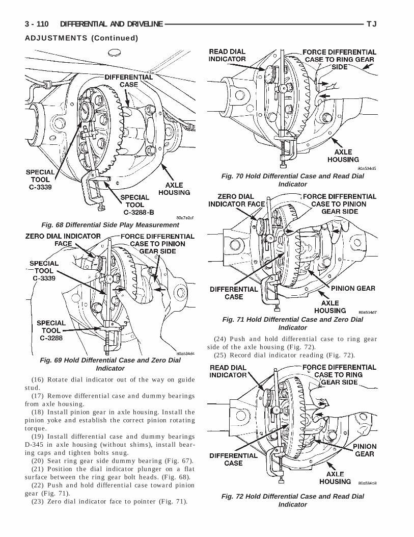
s
f
pt
Di
s
g
3 - 110 DIFFERENTIAL AND DRIVELINE TJ
ADJUSTMENTS (Continued)
(16) Rotate dial indicator out of the way on guidetud.(17) Remove differential case and dummy bearings
rom axle housing.(18) Install pinion gear in axle housing. Install the
inion yoke and establish the correct pinion rotatingorque.
(19) Install differential case and dummy bearings-345 in axle housing (without shims), install bear-
ng caps and tighten bolts snug.(20) Seat ring gear side dummy bearing (Fig. 67).(21) Position the dial indicator plunger on a flat
urface between the ring gear bolt heads. (Fig. 68).(22) Push and hold differential case toward pinion
ear (Fig. 71).(23) Zero dial indicator face to pointer (Fig. 71).
Fig. 68 Differential Side Play Measurement
Fig. 69 Hold Differential Case and Zero DialIndicator
(24) Push and hold differential case to ring gearside of the axle housing (Fig. 72).
(25) Record dial indicator reading (Fig. 72).
Fig. 70 Hold Differential Case and Read DialIndicator
Fig. 71 Hold Differential Case and Zero DialIndicator
Fig. 72 Hold Differential Case and Read DialIndicator

irs
tta
s
f
h
d
sc
t
s
g
a
ar0cn(
blvmc
G
G
walat
eg
TJ DIFFERENTIAL AND DRIVELINE 3 - 111
ADJUSTMENTS (Continued)
(26) Subtract 0.002 in. (0.05 mm) from the dialndicator reading to compensate for backlash betweening and pinion gears. This total is the thicknesshim required to achieve proper backlash.(27) Subtract the backlash shim thickness from
he total preload shim thickness. The remainder ishe shim thickness required on the pinion side of thexle housing.(28) Rotate dial indicator out of the way on guide
tud.(29) Remove differential case and dummy bearings
rom axle housing.(30) Install side bearing shims on differential case
ubs.(31) Install new side bearing cones and cups on
ifferential case.(32) Install spreader W-129-B on axle housing and
pread axle opening enough to receive differentialase.(33) Install differential case in axle housing. Refer
o Differential Removal and Installation paragraph.(34) Remove spreader from axle housing.(35) Rotate the differential case several times to
eat the side bearings.(36) Position the indicator plunger against a ring
ear tooth (Fig. 73).(37) Push and hold ring gear upward while not
llowing the pinion gear to rotate.(38) Zero dial indicator face to pointer.(39) Push and hold ring gear downward while not
llowing the pinion gear to rotate. Dial indicatoreading should be between 0.12 mm (0.005 in.) and.20 mm (0.008 in.). If backlash is not within specifi-ations transfer the necessary amount of shim thick-ess from one side of the axle housing to the otherFig. 74).
(40) Verify differential case and ring gear runouty measuring ring to pinion gear backlash at severalocations around the ring gear. Readings should notary more than 0.05 mm (0.002 in.). If readings varyore than specified, the ring gear or the differential
ase is defective.After the proper backlash is achieved, performear Contact Pattern Analysis procedure.
EAR CONTACT PATTERN ANALYSISThe ring and pinion gear teeth contact patternsill show if the pinion gear depth is correct in thexle housing. It will also show if the ring gear back-ash has been adjusted correctly. The backlash can bedjusted within specifications to achieve desiredooth contact patterns.
(1) Apply a thin coat of hydrated ferric oxide, orquivalent, to the drive and coast side of the ringear teeth.
(2) Wrap, twist, and hold a shop towel around thepinion yoke to increase the turning resistance of thepinion gear. This will provide a more distinct contactpattern.
(3) Using a boxed end wrench on a ring gear bolt,Rotate the differential case one complete revolutionin both directions while a load is being applied fromshop towel.
The areas on the ring gear teeth with the greatestdegree of contact against the pinion gear teeth willsqueegee the compound to the areas with the leastamount of contact. Note and compare patterns on thering gear teeth to Gear Tooth Contact Patterns chart(Fig. 75) and adjust pinion depth and gear backlashas necessary.
Fig. 73 Ring Gear Backlash Measurement
Fig. 74 Backlash Shim Adjustment

3 - 112 DIFFERENTIAL AND DRIVELINE TJ
ADJUSTMENTS (Continued)
Fig. 75 Gear Tooth Contact Patterns

S
2
2
S
2
TJ DIFFERENTIAL AND DRIVELINE 3 - 113
PECIFICATIONS
16 RBI AXLE
DESCRIPTION SPECIFICATIONAxle Type . . . . . . . . . . . . . . . . Semi-floating HypoidLubricant . . . . . . . . SAE Thermally Stable 80W–90Lubricant–Trailer Tow . . . . . . . . Synthetic 75W–140Lubricant Capacity . . . . . . . . . . . . . 1.89 L (4.0 pts.)Axle Ratios . . . . . . . . . . . . . . . . . . . . 3.07, 3.55, 4.10Differential Bearing Preload . . . . 0.1 mm (0.004 in.)Differential Side Gear Clearance . . . . . . 0–0.15 mm
(0–0.006 in.)Ring Gear Diameter . . . . . . . . . . . . 216 mm (8.5 in.)Ring Gear Backlash . . . 0.13–0.20 mm (0.005–0.008
in.)Pinion Depth . . . . . . . . . . . . . 109.52 mm (4.312 in.)Brg. Preload, Pinion (New) . . 2.26–4.52 N·m (20–40
in. lbs.)Brg. Preload, Pinion (Original) . 1–3 N·m (10–20 in.
lbs.)
16 RBI TORQUE
DESCRIPTION TORQUEPlug, Fill . . . . . . . . . . . . . . . . . . 34 N·m (25 ft. lbs.)Bolts, Diff. Cover . . . . . . . . . . . . 41 N·m (30 ft. lbs.)Bolts, Diff. Bearing Cap . . . . . . 108 N·m (80 ft. lbs.)Bolts, Ring Gear . . . . . . . . . . . . 108 N·m (80 ft. lbs.)Nuts, Brake Backing Plate . . . . . 61 N·m (45 ft. lbs.)Nut, Pinion Gear—Minimum . 217 N·m (160 ft. lbs.)
PECIAL TOOLS
16 RBI AXLE
Puller Set—C-293-M
Adapters—C-293-18
Adapters—C-293-48
Extension—C-293-3
Remover—C-452

3 - 114 DIFFERENTIAL AND DRIVELINE TJ
SPECIAL TOOLS (Continued)
Handle—C-4171
Installer—D-156
Pilot—C-3288-B
Dial Indicator—C-3339
Trac-lok Tool Set—C-4487
Installer—C-3972-A
Installer—D-144
Installer—D-145

TJ DIFFERENTIAL AND DRIVELINE 3 - 115
SPECIAL TOOLS (Continued)
Remover—D-147
Remover—D-148
Spreader—W-129-B
Installer—W-162–D
Cup—8109
Splitter—1130
Installer—W-262
Pinion Depth Set—6730
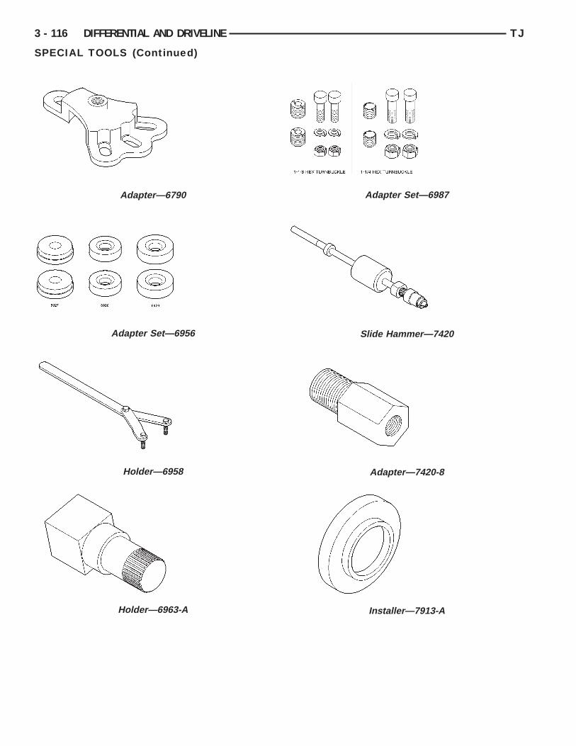
3 - 116 DIFFERENTIAL AND DRIVELINE TJ
SPECIAL TOOLS (Continued)
Adapter—6790
Adapter Set—6956
Holder—6958
Holder—6963-A
Adapter Set—6987
Slide Hammer—7420
Adapter—7420-8
Installer—7913-A