diaval - tecalemit flow · valve design: en 13397, en 12516 face to face length: en 558 series 1...
TRANSCRIPT

Diaval®
Diaphragm Valveswww.diaval.com
Weir Type Diaphragm Valves - DIAVAL® Series W
Copyright COMEVAL VALVE SYSTEMS © - Data subject to revision - Regularly updated data on www.comeval.es - DS09-W - Ed.17/06 2
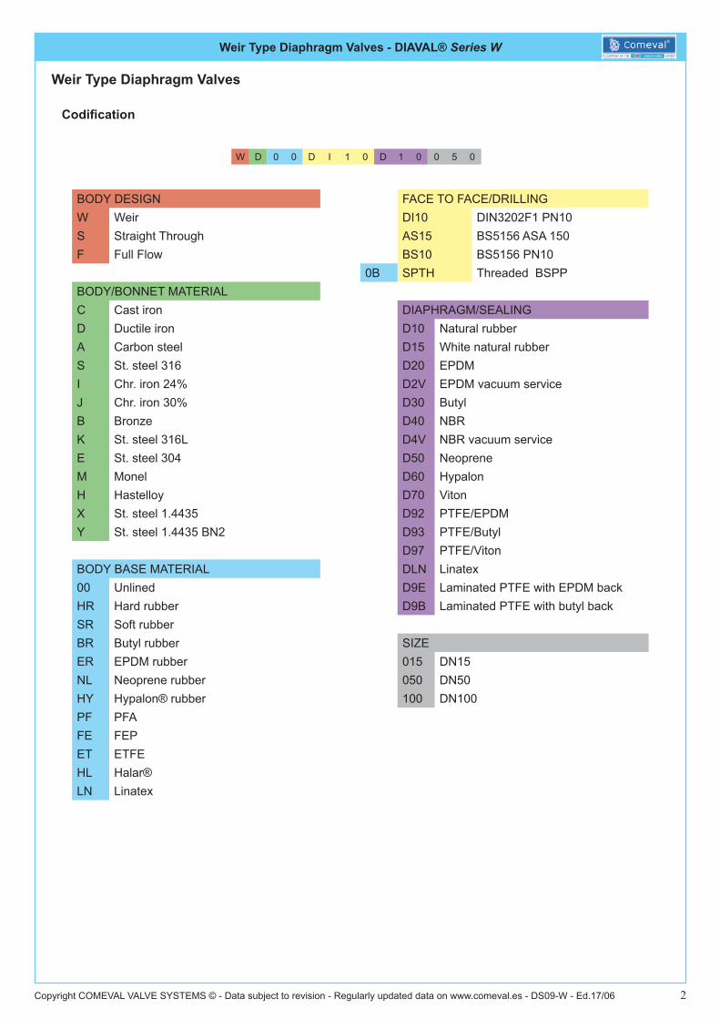
Codification
W D 0 0 D I 1 0 D 1 0 0 5 0
Weir Type Diaphragm Valves
BODY DESIGN FACE TO FACE/DRILLINGW Weir DI10 DIN3202F1 PN10 S Straight Through AS15 BS5156 ASA 150F Full Flow BS10 BS5156 PN10
0B SPTH Threaded BSPPBODY/BONNET MATERIALC Cast iron DIAPHRAGM/SEALINGD Ductile iron D10 Natural rubberA Carbon steel D15 White natural rubberS St. steel 316 D20 EPDMI Chr. iron 24% D2V EPDM vacuum serviceJ Chr. iron 30% D30 ButylB Bronze D40 NBRK St. steel 316L D4V NBR vacuum serviceE St. steel 304 D50 NeopreneM Monel D60 HypalonH Hastelloy D70 VitonX St. steel 1.4435 D92 PTFE/EPDMY St. steel 1.4435 BN2 D93 PTFE/Butyl
D97 PTFE/VitonBODY BASE MATERIAL DLN Linatex00 Unlined D9E Laminated PTFE with EPDM backHR Hard rubber D9B Laminated PTFE with butyl backSR Soft rubberBR Butyl rubber SIZEER EPDM rubber 015 DN15NL Neoprene rubber 050 DN50HY Hypalon® rubber 100 DN100PF PFAFE FEPET ETFEHL Halar®LN Linatex
Weir Type Diaphragm Valves - DIAVAL® Series W
Copyright COMEVAL VALVE SYSTEMS © - Data subject to revision - Regularly updated data on www.comeval.es - DS09-W - Ed.17/06 3
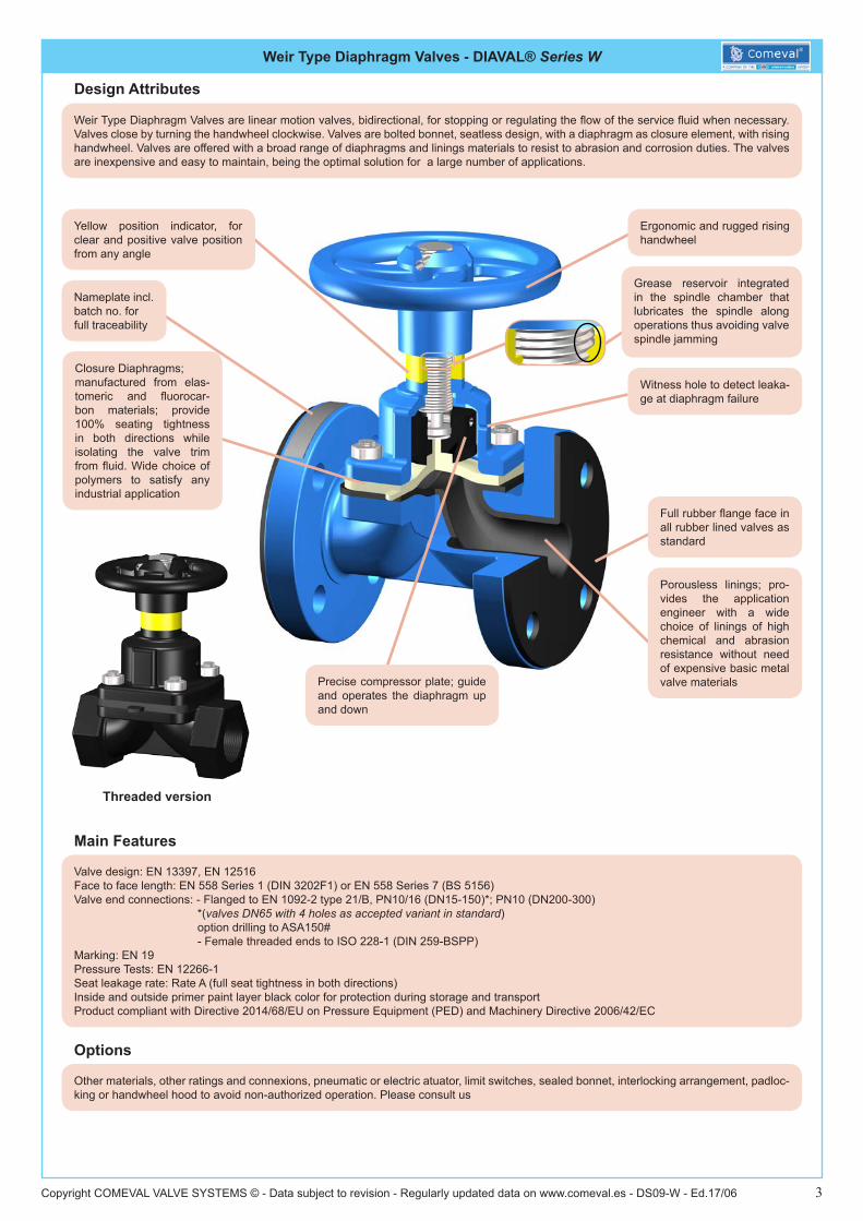
Weir Type Diaphragm Valves are linear motion valves, bidirectional, for stopping or regulating the flow of the service fluid when necessary. Valves close by turning the handwheel clockwise. Valves are bolted bonnet, seatless design, with a diaphragm as closure element, with rising handwheel. Valves are offered with a broad range of diaphragms and linings materials to resist to abrasion and corrosion duties. The valves are inexpensive and easy to maintain, being the optimal solution for a large number of applications.
Main Features
Valve design: EN 13397, EN 12516Face to face length: EN 558 Series 1 (DIN 3202F1) or EN 558 Series 7 (BS 5156)Valve end connections: - Flanged to EN 1092-2 type 21/B, PN10/16 (DN15-150)*; PN10 (DN200-300)
*(valves DN65 with 4 holes as accepted variant in standard)option drilling to ASA150#- Female threaded ends to ISO 228-1 (DIN 259-BSPP)
Marking: EN 19Pressure Tests: EN 12266-1Seat leakage rate: Rate A (full seat tightness in both directions) Inside and outside primer paint layer black color for protection during storage and transport Product compliant with Directive 2014/68/EU on Pressure Equipment (PED) and Machinery Directive 2006/42/EC
Options
Other materials, other ratings and connexions, pneumatic or electric atuator, limit switches, sealed bonnet, interlocking arrangement, padloc-king or handwheel hood to avoid non-authorized operation. Please consult us
Threaded version
Ergonomic and rugged rising handwheel
Porousless linings; pro-vides the application engineer with a wide choice of linings of high chemical and abrasion resistance without need of expensive basic metal valve materials
Yellow position indicator, for clear and positive valve position from any angle
Precise compressor plate; guide and operates the diaphragm up and down
Nameplate incl. batch no. for full traceability
Closure Diaphragms;manufactured from elas-tomeric and fluorocar-bon materials; provide 100% seating tightness in both directions while isolating the valve trim from fluid. Wide choice of polymers to satisfy any industrial application
Witness hole to detect leaka-ge at diaphragm failure
Full rubber flange face in all rubber lined valves as standard
Design Attributes
Grease reservoir integrated in the spindle chamber that lubricates the spindle along operations thus avoiding valve spindle jamming

Weir Type Diaphragm Valves - DIAVAL® Series W
Copyright COMEVAL VALVE SYSTEMS © - Data subject to revision - Regularly updated data on www.comeval.es - DS09-W - Ed.17/06 4
Main Duties / Limits of use
Bodies (Ductile iron)
Linings
Diaphragms
Temperature Values are for neutral fluids and not plotted against any pressure parameter, the application engineer should consider that working limits are affected by the actual pressure / temperature relationship.Temperature values also depends on medium through the valve.
Liquids compatible with materials of construction, acc. to Directive 2014/68/EU Annex II tables 8 (group 1*) & 9 (group 2*) up to category IRubber Diaph.
PS:16 bar DN10-50 (Art.4-Parr.3)PS:10 bar DN65-150 (Art.4-Parr.3)PS:6 bar DN200 (Art.4-Parr.3)PS:5 bar DN250 (Art.4-Parr.3)PS:4 bar DN300 (Art.4-Parr.3)
PTFE Diaph.PS:10 bar DN10-125 (Art.4-Parr.3)PS:6 bar DN150 (Art.4-Parr.3)
Combination of Body + Lining + Diaphragm determines the P-T limit of use of the valveQuestions referring to chemical resistance, please consult usObserve also pressure/temperature limits on diagrams under*Classification of fluids (group 1 or 2) acc. to Directive 2014/68/EU, Article 13
Brief Peak Temperature (less than one hour)
Weir Type Diaphragm Valves - DIAVAL® Series W
Copyright COMEVAL VALVE SYSTEMS © - Data subject to revision - Regularly updated data on www.comeval.es - DS09-W - Ed.17/06 5
A valve flow coefficient represents the standard flow rate which flows through the valve at a given opening, referred to pre-established conditions:
* Kv value is the volume of water at 20ºC, in cubic meters per hour (m3/h), that will flow through the valve at a static pressure drop of 1 bar across the valve
* Cv value is the volume of water at 60ºF, in gallons per minute (gpm), that will flow through the valve at a static pressure drop of 1 psi across the valve
Conversion from Kv to Cv can be roughly calculated by means of the following expression:Cv = Kv x 1,17
Flow rate through the valve with other liquids can be calculated with the following expressions
Kv = q (SG / dp)1/2whereq = water flow (cubic meter per hour)SG = specific gravity (1 for water)dp = pressure drop (bar)
Cv = q (SG / dp)1/2whereq = water flow (US gallons per minute)SG = specific gravity (1 for water)dp = pressure drop (psi)
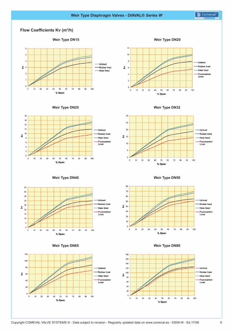
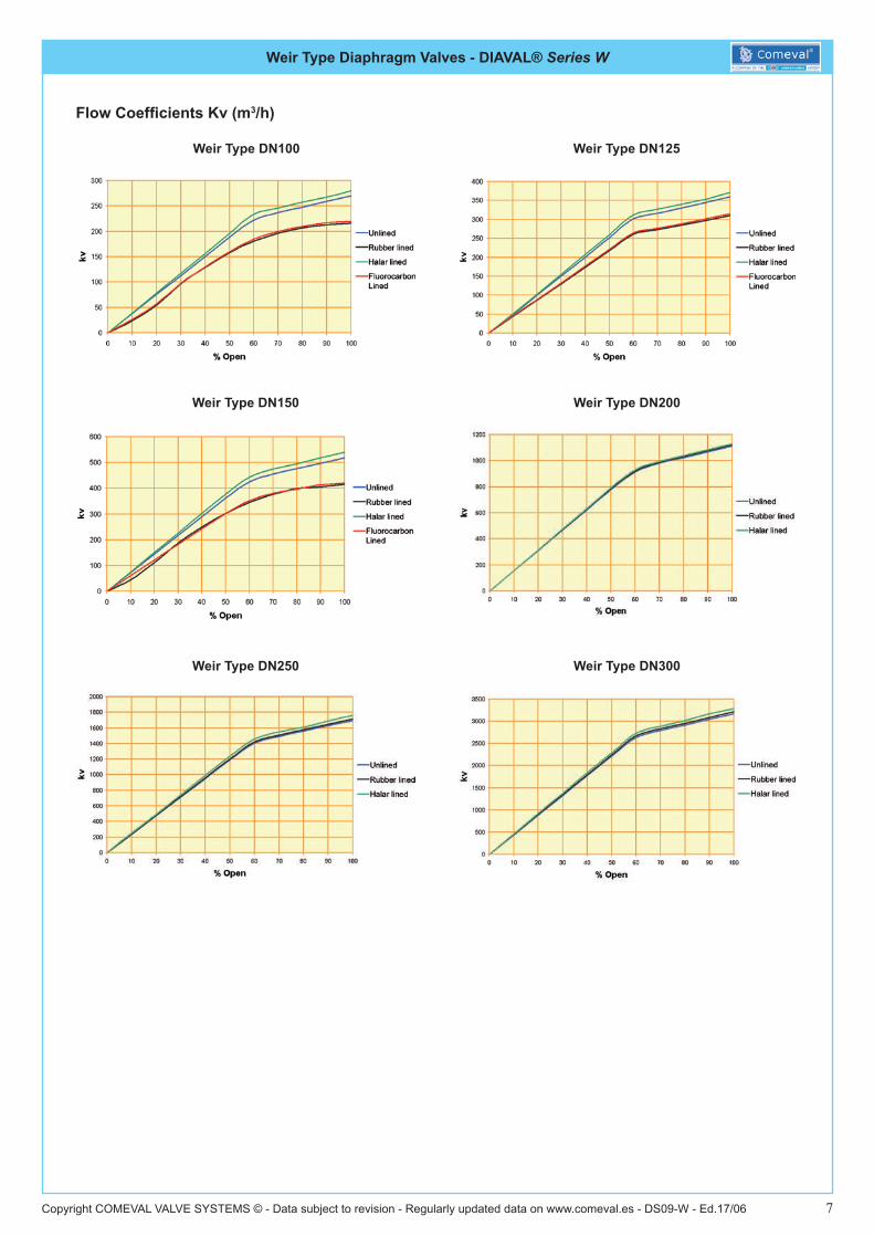
How to use the graphs:
The flow graphs in the following sheets provide the valve flow rate across the valve body at a determine opening degree.
Choose the graph heading the valve Nominal Diameter which is being looked for; consider the valve inner lining features from a choice of unlined, rubber lined, ECTFE (Halar) lined or Fluoropolymer coated valve bodies and plot an intersection line upwards from the opening degree (in case of throttling) or full open to the colour representing the lining. The vertical axis will give the Kv value expressed in M³/h.
Valves Flow Data
Weir Type Diaphragm Valves - DIAVAL® Series W
Copyright COMEVAL VALVE SYSTEMS © - Data subject to revision - Regularly updated data on www.comeval.es - DS09-W - Ed.17/06 6
Flow Coefficients Kv (m3/h)
Weir Type DN15 Weir Type DN20
Weir Type DN25 Weir Type DN32
Weir Type DN40 Weir Type DN50
Weir Type DN65 Weir Type DN80
Weir Type Diaphragm Valves - DIAVAL® Series W
Copyright COMEVAL VALVE SYSTEMS © - Data subject to revision - Regularly updated data on www.comeval.es - DS09-W - Ed.17/06 7
Flow Coefficients Kv (m3/h)
Weir Type DN100 Weir Type DN125
Weir Type DN150 Weir Type DN200
Weir Type DN250 Weir Type DN300

Weir Type Diaphragm Valves - DIAVAL® Series W
Copyright COMEVAL VALVE SYSTEMS © - Data subject to revision - Regularly updated data on www.comeval.es - DS09-W - Ed.17/06 8
NO. PART MATERIAL
1BODY WC_ Cast iron EN-JL1040 (GG25)
WD_ Ductile iron EN-JS1030 (GGG40)
2 DIAPHRAGMRUBBER
Natural (D10) / EPDM (D20) / Butyl (D30) / Nitrile (D40) / Neoprene (D50) /
Hypalon (D60) / Viton (D70)
PTFE + EPDM (D92) / PTFE + Butyl (D93) / PTFE + Viton (D97)
3 COMPRESSOR Cast iron EN-JL1040 (GG25)
4 BONNETWC_ Cast iron EN-JL1040 (GG25)
WD_ Ductile iron EN-JS1030 (GGG40)
Main Valve Parameters
Unlined valves with flanged ends
Dimensions in mm subject to manufacturing tolerance / Weights in kg
Information / restriction of technical rules need to be observed!Installation, Operating and Maintenance Manual can be downloaded at www.comeval.es
The engineer, designing a system or a plant, is responsable for the selection of the correct valveProduct suitability must be verified, contact manufacturer for information
DN 15 20 25 32 40 50 65
LEN 558 S7 (BS 5156) 108 114 127 146 159 190 216
EN 558 S1 (DIN 3202 F1) 130 150 160 180 200 230 290H (open) 109 117 140 143 172 190 230
H1 (close) 103 109 130 131 152 166 195a 52 67 75 88 110 127 146
ØW 100 100 120 120 120 164 220
FLA
NG
ED E
ND
S TO
EN
PN
10
ØD 95 105 115 140 150 165 185C 14 16 16 18 18 20 20
ØR 45 58 68 78 88 102 122f 2 2 2 2 3 3 3
nxØd 4x14 4x14 4x14 4x18 4x18 4x18 4x18ØK 65 75 85 100 110 125 145
FLA
NG
ED E
ND
S TO
ASA
150#
*
ØD 89 98 108 117 127 152 178C 11,5 11,5 11,5 13 14,5 16 17,5
ØR 35 43 51 64 73 92 105f 1,6 1,6 1,6 1,6 1,6 1,6 1,6
nxØd 4x16 4x16 4x16 4x16 4x16 4x19 4x19ØK 60,3 69,8 79,4 88,9 98,4 120,6 139,7
Approx. Weight
EN 558 S7 (BS 5156) 2,3 3,2 4,2 6,4 7,5 12 18 EN 558 S1 (DIN 3202 F1) 2,7 3,5 4,4 6,6 8,5 12,5 19
NO. PART MATERIAL5 SPINDLE Steel
6 HANDWHEEL Cast iron EN-JL1040 (GG25)
7 H/W DOWEL PIN Steel (EN42)
8 BODY STUDS Steel
9 BODY NUTS Steel
10 THRUST WASHER Nylon
11 COMP. PIN Steel (EN42)
*Unless specific agreement with COMEVAL, valves with flanges 150# will be usually supplied as EN/DIN flanges with 150# drilling, since pressure is limited to EN/DIN
Main Parts and Materials

Weir Type Diaphragm Valves - DIAVAL® Series W
Copyright COMEVAL VALVE SYSTEMS © - Data subject to revision - Regularly updated data on www.comeval.es - DS09-W - Ed.17/06 9
Main Valve Parameters
Unlined valves with flanged ends
Dimensions in mm subject to manufacturing tolerance / Weights in kg
Information / restriction of technical rules need to be observed!Installation, Operating and Maintenance Manual can be downloaded at www.comeval.es
The engineer, designing a system or a plant, is responsable for the selection of the correct valveProduct suitability must be verified, contact manufacturer for information
DN 80 100 125 150 200 250 300
LEN 558 S7 (BS 5156) 254 305 356 406 521 635 749
EN 558 S1 (DIN 3202 F1) 310 350 400 480 600 730 850H (open) 242 326 391 468 680 802 971
H1 (close) 202 275 326 390 560 657 796a 190 Ø230 Ø265 Ø320 Ø420 Ø502 Ø569
ØW 240 270 270 360 460 600 700
FLA
NG
ED E
ND
S TO
EN
PN
10
ØD 200 220 250 285 340 395 445C 22 24 26 26 26 28 28
ØR 138 158 188 212 268 320 370f 3 3 3 3 3 3 4
nxØd 8x18 8x18 8x18 8x22 8x22 12x22 12x22ØK 160 180 210 240 295 350 400
FLA
NG
ED E
ND
S TO
ASA
150#
*
ØD 191 229 254 279 343 406 483
C 19,5 24 24 25,5 29 30,5 32ØR 127 157 186 216 270 324 381
f 1,6 1,6 1,6 1,6 1,6 1,6 1,6nxØd 4x19 8x19 8x22 8x22 8x22 12x22 12x22ØK 152,4 190,5 215,9 241,3 298,4 361,9 431,8
Approx. Weight
EN 558 S7 (BS 5156) 23 34 50 69 150 220 300 EN 558 S1 (DIN 3202 F1) 25 36 52 75 160 235 315
*Unless specific agreement with COMEVAL, valves with flanges 150# will be usually supplied as EN/DIN flanges with 150# drilling, since pressure is limited to EN/DIN

Weir Type Diaphragm Valves - DIAVAL® Series W
Copyright COMEVAL VALVE SYSTEMS © - Data subject to revision - Regularly updated data on www.comeval.es - DS09-W - Ed.17/06 10
NO. PART MATERIAL
1 BODYWC_ Cast iron EN-JL1040 (GG25)
WD_ Ductile iron EN-JS1030 (GGG40)
1A LINING
_HR_ Hard rubber
_SR_ Soft rubber
_BR_ Butyl rubber
_ER_ EPDM rubber
_NL_ Neoprene rubber
2 DIAPHRAGM + BACKING
RUBBERNatural (D10) / EPDM (D20) / Butyl (D30) /
Nitrile (D40) / Neoprene (D50) / Hypalon (D60) / Viton (D70)
PTFE + EPDM (D92) / PTFE + Butyl (D93) / PTFE + Viton (D97)
Main Valve ParametersDN 15 20 25 32 40 50 65
LEN 558 S7 (BS 5156) 114 123 133 152 165 196 222
EN 558 S1 (DIN 3202 F1) 130 150 160 180 200 230 290H (open) 112 120 143 145 175 193 233
H1 (close) 106 112 133 134 155 169 198f 3 3 3 3 3 3 3a 52 67 75 88 110 127 146
ØW 100 100 120 120 120 164 220
FLA
NG
ED
END
S TO
EN
PN
10
ØD 95 105 115 140 150 165 185C 14 16 16 18 18 20 20
nxØd 4x14 4x14 4x14 4x18 4x18 4x18 4x18ØK 65 75 85 100 110 125 145
FLA
NG
ED
END
S TO
A
SA15
0#* ØD 89 98 108 117 127 152 178
C 11,5 11,5 11,5 13 14,5 16 17,5nxØd 4x16 4x16 4x16 4x16 4x16 4x19 4x19ØK 60,3 69,8 79,4 88,9 98,4 120,6 139,7
Approx. Weight
EN 558 S7 (BS 5156) 3,2 3,4 4,7 7 8,5 12 22
EN 558 S1 (DIN 3202 F1) 3,5 3,7 5 8,2 9,5 13,3 22,5
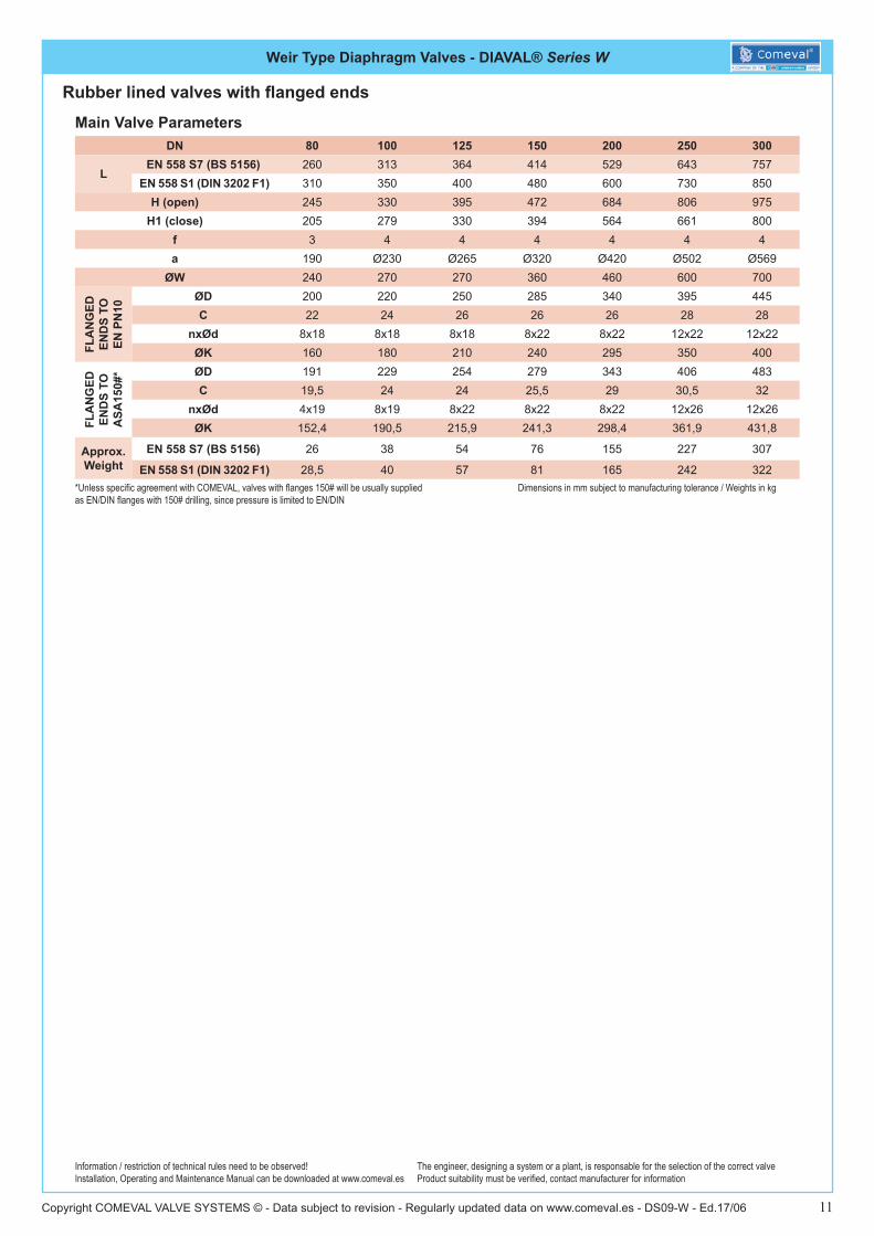
Rubber lined valves with flanged ends
Dimensions in mm subject to manufacturing tolerance / Weights in kg
Information / restriction of technical rules need to be observed!Installation, Operating and Maintenance Manual can be downloaded at www.comeval.es
The engineer, designing a system or a plant, is responsable for the selection of the correct valveProduct suitability must be verified, contact manufacturer for information
NO. PART MATERIAL3 COMPRESSOR Cast iron EN-JL1040 (GG25)
4 BONNETWC_ Cast iron EN-JL1040 (GG25)
WD_ Ductile iron EN-JS1030 (GGG40)
5 SPINDLE Steel
6 HANDWHEEL Cast iron EN-JL1040 (GG25)
7 H/W DOWEL PIN Steel (EN42)
8 BODY STUDS Steel
9 BODY NUTS Steel
10 THRUST WASHER Nylon
11 COMP. PIN Steel (EN42)
*Unless specific agreement with COMEVAL, valves with flanges 150# will be usually supplied as EN/DIN flanges with 150# drilling, since pressure is limited to EN/DIN
Main Parts and Materials
Weir Type Diaphragm Valves - DIAVAL® Series W
Copyright COMEVAL VALVE SYSTEMS © - Data subject to revision - Regularly updated data on www.comeval.es - DS09-W - Ed.17/06 11
Main Valve ParametersDN 80 100 125 150 200 250 300
LEN 558 S7 (BS 5156) 260 313 364 414 529 643 757
EN 558 S1 (DIN 3202 F1) 310 350 400 480 600 730 850H (open) 245 330 395 472 684 806 975
H1 (close) 205 279 330 394 564 661 800f 3 4 4 4 4 4 4a 190 Ø230 Ø265 Ø320 Ø420 Ø502 Ø569
ØW 240 270 270 360 460 600 700
FLA
NG
ED
END
S TO
EN
PN
10
ØD 200 220 250 285 340 395 445C 22 24 26 26 26 28 28
nxØd 8x18 8x18 8x18 8x22 8x22 12x22 12x22ØK 160 180 210 240 295 350 400
FLA
NG
ED
END
S TO
A
SA15
0#* ØD 191 229 254 279 343 406 483
C 19,5 24 24 25,5 29 30,5 32nxØd 4x19 8x19 8x22 8x22 8x22 12x26 12x26ØK 152,4 190,5 215,9 241,3 298,4 361,9 431,8
Approx. Weight
EN 558 S7 (BS 5156) 26 38 54 76 155 227 307
EN 558 S1 (DIN 3202 F1) 28,5 40 57 81 165 242 322
Rubber lined valves with flanged ends
Dimensions in mm subject to manufacturing tolerance / Weights in kg
Information / restriction of technical rules need to be observed!Installation, Operating and Maintenance Manual can be downloaded at www.comeval.es
The engineer, designing a system or a plant, is responsable for the selection of the correct valveProduct suitability must be verified, contact manufacturer for information
*Unless specific agreement with COMEVAL, valves with flanges 150# will be usually supplied as EN/DIN flanges with 150# drilling, since pressure is limited to EN/DIN
Weir Type Diaphragm Valves - DIAVAL® Series W
Copyright COMEVAL VALVE SYSTEMS © - Data subject to revision - Regularly updated data on www.comeval.es - DS09-W - Ed.17/06 12
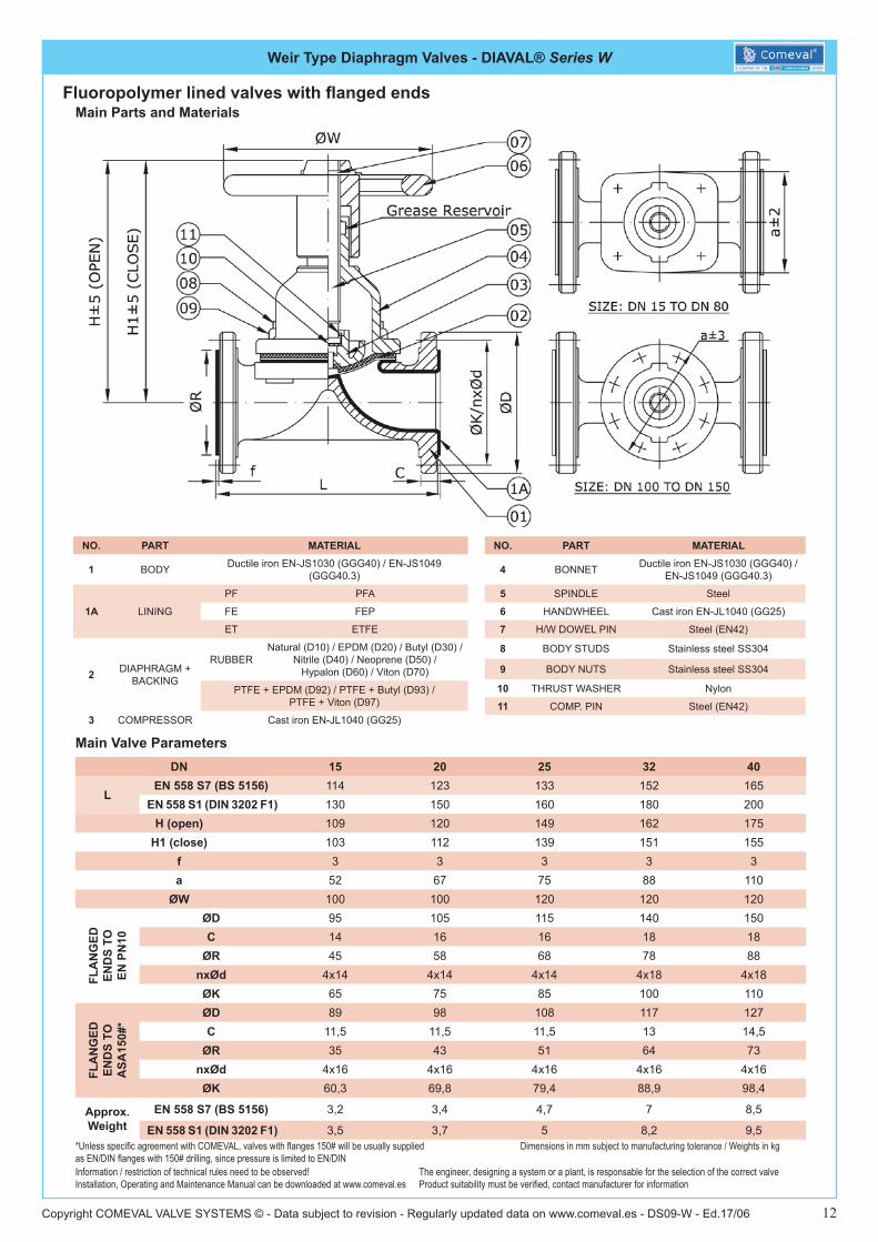
Main Parts and Materials
Main Valve Parameters
Fluoropolymer lined valves with flanged ends
Dimensions in mm subject to manufacturing tolerance / Weights in kg
Information / restriction of technical rules need to be observed!Installation, Operating and Maintenance Manual can be downloaded at www.comeval.es
The engineer, designing a system or a plant, is responsable for the selection of the correct valveProduct suitability must be verified, contact manufacturer for information
DN 15 20 25 32 40
LEN 558 S7 (BS 5156) 114 123 133 152 165
EN 558 S1 (DIN 3202 F1) 130 150 160 180 200H (open) 109 120 149 162 175
H1 (close) 103 112 139 151 155f 3 3 3 3 3a 52 67 75 88 110
ØW 100 100 120 120 120
FLA
NG
ED
END
S TO
EN
PN
10
ØD 95 105 115 140 150C 14 16 16 18 18
ØR 45 58 68 78 88nxØd 4x14 4x14 4x14 4x18 4x18ØK 65 75 85 100 110
FLA
NG
ED
END
S TO
A
SA15
0#*
ØD 89 98 108 117 127C 11,5 11,5 11,5 13 14,5
ØR 35 43 51 64 73nxØd 4x16 4x16 4x16 4x16 4x16ØK 60,3 69,8 79,4 88,9 98,4
Approx. Weight
EN 558 S7 (BS 5156) 3,2 3,4 4,7 7 8,5
EN 558 S1 (DIN 3202 F1) 3,5 3,7 5 8,2 9,5
NO. PART MATERIAL
4 BONNET Ductile iron EN-JS1030 (GGG40) / EN-JS1049 (GGG40.3)
5 SPINDLE Steel
6 HANDWHEEL Cast iron EN-JL1040 (GG25)
7 H/W DOWEL PIN Steel (EN42)
8 BODY STUDS Stainless steel SS304
9 BODY NUTS Stainless steel SS304
10 THRUST WASHER Nylon
11 COMP. PIN Steel (EN42)
NO. PART MATERIAL
1 BODY Ductile iron EN-JS1030 (GGG40) / EN-JS1049 (GGG40.3)
1A LINING
PF PFA
FE FEP
ET ETFE
2 DIAPHRAGM + BACKING
RUBBERNatural (D10) / EPDM (D20) / Butyl (D30) /
Nitrile (D40) / Neoprene (D50) / Hypalon (D60) / Viton (D70)
PTFE + EPDM (D92) / PTFE + Butyl (D93) / PTFE + Viton (D97)
3 COMPRESSOR Cast iron EN-JL1040 (GG25)
*Unless specific agreement with COMEVAL, valves with flanges 150# will be usually supplied as EN/DIN flanges with 150# drilling, since pressure is limited to EN/DIN

Weir Type Diaphragm Valves - DIAVAL® Series W
Copyright COMEVAL VALVE SYSTEMS © - Data subject to revision - Regularly updated data on www.comeval.es - DS09-W - Ed.17/06 13
Main Valve Parameters
Fluoropolymer lined valves with flanged ends
Dimensions in mm subject to manufacturing tolerance / Weights in kg
Information / restriction of technical rules need to be observed!Installation, Operating and Maintenance Manual can be downloaded at www.comeval.es
The engineer, designing a system or a plant, is responsable for the selection of the correct valveProduct suitability must be verified, contact manufacturer for information
DN 50 65 80 100 125 150
LEN 558 S7 (BS 5156) 196 222 260 313 364 414
EN 558 S1 (DIN 3202 F1) 230 290 310 350 400 480H (open) 190 253 243 327 392 462
H1 (close) 166 218 203 276 328 384f 3 3 3 4 4 4a 127 146 190 Ø230 Ø265 Ø320
ØW 164 220 240 270 270 360
FLA
NG
ED
END
S TO
EN
PN
10
ØD 165 185 200 220 250 285C 20 20 22 24 26 26
ØR 102 122 138 158 188 212nxØd 4x18 4x18 8x18 8x18 8x18 8x22ØK 125 145 160 180 210 240
FLA
NG
ED
END
S TO
A
SA15
0#*
ØD 152 178 191 229 254 279C 16 17,5 19,5 24 24 25,5
ØR 92 105 127 157 186 216nxØd 4x19 4x19 4x19 8x19 8x22 8x22ØK 120,6 139,7 152,4 190,5 215,9 241,3
Approx. Weight
EN 558 S7 (BS 5156) 12 22 26 38 54 76
EN 558 S1 (DIN 3202 F1) 13,3 22,5 28,5 40 57 81*Unless specific agreement with COMEVAL, valves with flanges 150# will be usually supplied as EN/DIN flanges with 150# drilling, since pressure is limited to EN/DIN
Weir Type Diaphragm Valves - DIAVAL® Series W
Copyright COMEVAL VALVE SYSTEMS © - Data subject to revision - Regularly updated data on www.comeval.es - DS09-W - Ed.17/06 14
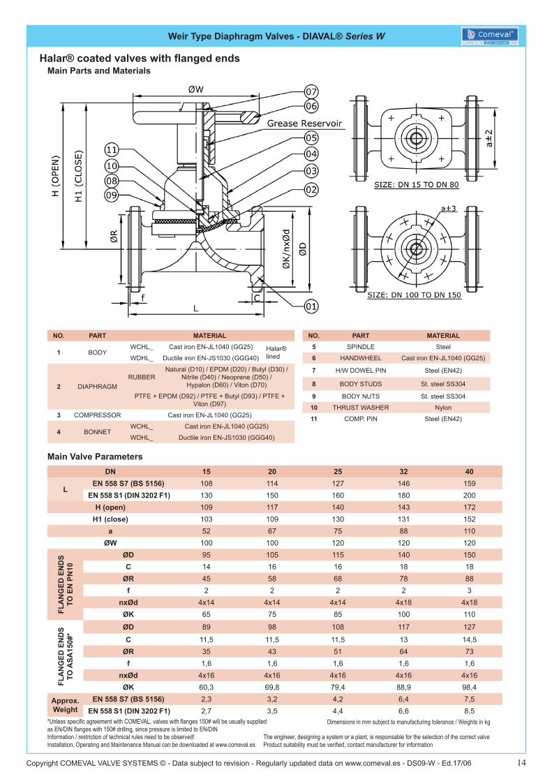
Main Parts and Materials
Main Valve Parameters
Halar® coated valves with flanged ends
Dimensions in mm subject to manufacturing tolerance / Weights in kg
Information / restriction of technical rules need to be observed!Installation, Operating and Maintenance Manual can be downloaded at www.comeval.es
The engineer, designing a system or a plant, is responsable for the selection of the correct valveProduct suitability must be verified, contact manufacturer for information
NO. PART MATERIAL
1 BODYWCHL_ Cast iron EN-JL1040 (GG25) Halar®
linedWDHL_ Ductile iron EN-JS1030 (GGG40)
2 DIAPHRAGMRUBBER
Natural (D10) / EPDM (D20) / Butyl (D30) / Nitrile (D40) / Neoprene (D50) /
Hypalon (D60) / Viton (D70)
PTFE + EPDM (D92) / PTFE + Butyl (D93) / PTFE + Viton (D97)
3 COMPRESSOR Cast iron EN-JL1040 (GG25)
4 BONNETWCHL_ Cast iron EN-JL1040 (GG25)
WDHL_ Ductile iron EN-JS1030 (GGG40)
DN 15 20 25 32 40
LEN 558 S7 (BS 5156) 108 114 127 146 159
EN 558 S1 (DIN 3202 F1) 130 150 160 180 200H (open) 109 117 140 143 172
H1 (close) 103 109 130 131 152a 52 67 75 88 110
ØW 100 100 120 120 120
FLA
NG
ED E
ND
S TO
EN
PN
10
ØD 95 105 115 140 150C 14 16 16 18 18
ØR 45 58 68 78 88f 2 2 2 2 3
nxØd 4x14 4x14 4x14 4x18 4x18ØK 65 75 85 100 110
FLA
NG
ED E
ND
S TO
ASA
150#
*
ØD 89 98 108 117 127
C 11,5 11,5 11,5 13 14,5ØR 35 43 51 64 73
f 1,6 1,6 1,6 1,6 1,6nxØd 4x16 4x16 4x16 4x16 4x16ØK 60,3 69,8 79,4 88,9 98,4
Approx. Weight
EN 558 S7 (BS 5156) 2,3 3,2 4,2 6,4 7,5 EN 558 S1 (DIN 3202 F1) 2,7 3,5 4,4 6,6 8,5
NO. PART MATERIAL5 SPINDLE Steel
6 HANDWHEEL Cast iron EN-JL1040 (GG25)
7 H/W DOWEL PIN Steel (EN42)
8 BODY STUDS St. steel SS304
9 BODY NUTS St. steel SS304
10 THRUST WASHER Nylon
11 COMP. PIN Steel (EN42)
*Unless specific agreement with COMEVAL, valves with flanges 150# will be usually supplied as EN/DIN flanges with 150# drilling, since pressure is limited to EN/DIN
Weir Type Diaphragm Valves - DIAVAL® Series W
Copyright COMEVAL VALVE SYSTEMS © - Data subject to revision - Regularly updated data on www.comeval.es - DS09-W - Ed.17/06 15
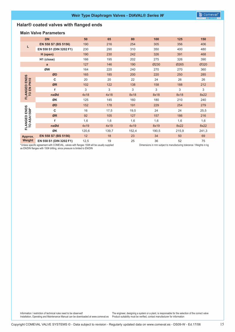
Main Valve Parameters
Halar® coated valves with flanged ends
Dimensions in mm subject to manufacturing tolerance / Weights in kg
Information / restriction of technical rules need to be observed!Installation, Operating and Maintenance Manual can be downloaded at www.comeval.es
The engineer, designing a system or a plant, is responsable for the selection of the correct valveProduct suitability must be verified, contact manufacturer for information
DN 50 65 80 100 125 150
LEN 558 S7 (BS 5156) 190 216 254 305 356 406
EN 558 S1 (DIN 3202 F1) 230 290 310 350 400 480H (open) 190 230 242 326 391 468
H1 (close) 166 195 202 275 326 390a 127 146 190 Ø230 Ø265 Ø320
ØW 164 220 240 270 270 360
FLA
NG
ED E
ND
S TO
EN
PN
10
ØD 165 185 200 220 250 285C 20 20 22 24 26 26
ØR 102 122 138 158 188 212f 3 3 3 3 3 3
nxØd 4x18 4x18 8x18 8x18 8x18 8x22ØK 125 145 160 180 210 240
FLA
NG
ED E
ND
S TO
ASA
150#
*
ØD 152 178 191 229 254 279
C 16 17,5 19,5 24 24 25,5ØR 92 105 127 157 186 216
f 1,6 1,6 1,6 1,6 1,6 1,6nxØd 4x19 4x19 4x19 8x19 8x22 8x22ØK 120,6 139,7 152,4 190,5 215,9 241,3
Approx. Weight
EN 558 S7 (BS 5156) 12 18 23 34 50 69 EN 558 S1 (DIN 3202 F1) 12,5 19 25 36 52 75
*Unless specific agreement with COMEVAL, valves with flanges 150# will be usually supplied as EN/DIN flanges with 150# drilling, since pressure is limited to EN/DIN

Weir Type Diaphragm Valves - DIAVAL® Series W
Copyright COMEVAL VALVE SYSTEMS © - Data subject to revision - Regularly updated data on www.comeval.es - DS09-W - Ed.17/06 16
Main Valve Parameters
Unlined threaded valves
Dimensions in mm subject to manufacturing tolerance / Weights in kg
Information / restriction of technical rules need to be observed!Installation, Operating and Maintenance Manual can be downloaded at www.comeval.es
The engineer, designing a system or a plant, is responsable for the selection of the correct valveProduct suitability must be verified, contact manufacturer for information
DN 10 15 20 25 32 40 50 65 80
L(1) 50 66 85 110 124 140 165 203 254(2) - 108 117 127 146 159 190 - -
H (open)(1) 70 70 105 122 148 155 183 212 256(2) - 106 117 141 152 176 196 - -
ØW(1) 45 75 75 85 120 120 120 165 230(2) - 100 100 120 120 120 164 - -
e 42 52 67 75 88 110 127 146 190Approx. Weight 1,2 1,5 2 3,2 4 6 8 11 18
Main Parts and Materials
NO. PART MATERIAL
1 BODY
WC_ Cast iron EN-JL1040 (GG25)
WD_ Ductile iron EN-JS1030 (GGG40)
WS_ St. steel
2 DIAPHRAGMRUBBER
Natural (D10) / EPDM (D20) / Butyl (D30) / Nitrile (D40) / Neoprene (D50) /
Hypalon (D60) / Viton (D70)
PTFE + EPDM (D92) / PTFE + Butyl (D93) / PTFE + Viton (D97)
3 COMPRESSOR Cast iron EN-JL1040 (GG25)
4 BONNET
WC_ Cast iron EN-JL1040 (GG25)
WD_ Ductile iron EN-JS1030 (GGG40)
WS_ St. steel
5 SPINDLE Steel
6 HANDWHEEL Cast iron EN-JL1040 (GG25)
7 H/W DOWEL PIN Steel (EN42)
8 BODY STUDS Steel
9 BODY NUTS Steel
10 THRUST WASHER Nylon
(1) Standard dimensions for cast and ductile iron valves(2) Standard dimensions for st. steel valves

Weir Type Diaphragm Valves - DIAVAL® Series W
Copyright COMEVAL VALVE SYSTEMS © - Data subject to revision - Regularly updated data on www.comeval.es - DS09-W - Ed.17/06 17
Main Bonnet Dimensions
Dimensions in mm subject to manufacturing tolerance / Weights in kg
DN ab
ØPCD d h h1 ØK NxØD WeightANGLES BETWEEN THE HOLES
F G H J15 33 37 52 84 78 100 4x6,5 0,9 --- --- --- ---20 40 44 67 90 82 100 4x7 1,1 --- --- --- ---25 46 54 75 115 105 120 4x9 2,0 --- --- --- ---32 60 67 88 117 106 120 4x9 2,0 --- --- --- ---40 65 70 110 133 113 120 4x11 2,5 --- --- --- ---50 78 83 127 155 131 164 4x11 4,5 --- --- --- ---65 95 102 146 194 159 220 4x13 8,5 --- --- --- ---80 114 127 190 201 161 240 4x16,5 9,5 --- --- --- ---
100 Ø194 Ø230 258 207 270 8x13 14,5 40º 42º 56º ---125 Ø222 Ø265 307 243 270 8x16,5 18,5 43º20’ 43º20’ 50º ---150 Ø273 Ø320 358 280 360 10x16 27,0 35º 35º 40º ---200 Ø381 Ø420 549 429 460 14x16 63,0 22º30’ 22º30’ 27º 36º250 Ø438 Ø502 697 552 600 14x21 90,0 22º30’ 22º30’ 22º30’ 45º300 Ø508 Ø569 804 629 700 14x21 147,0 24º 24º 24º 36º
Weir Type Diaphragm Valves - DIAVAL® Series W
Copyright COMEVAL VALVE SYSTEMS © - Data subject to revision - Regularly updated data on www.comeval.es - DS09-W - Ed.17/06 18
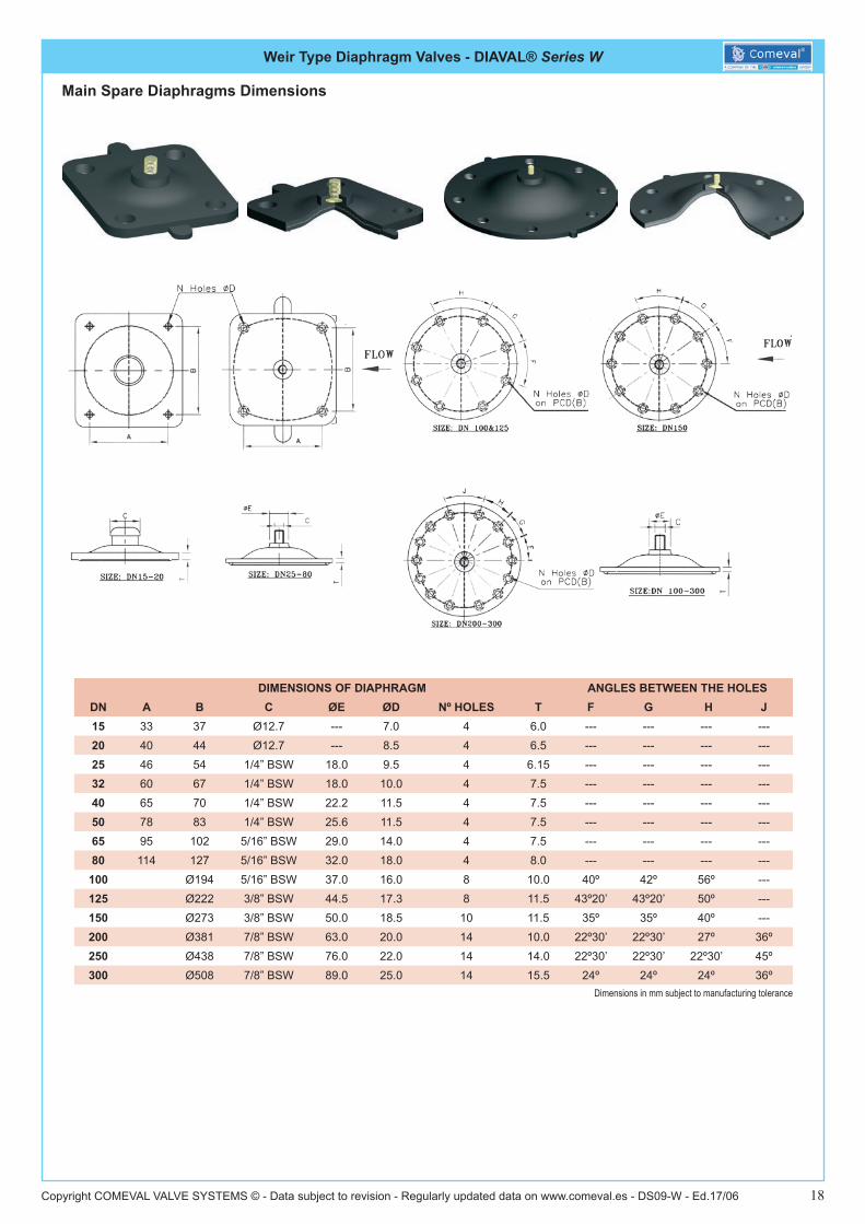
Dimensions in mm subject to manufacturing tolerance
Main Spare Diaphragms Dimensions
DIMENSIONS OF DIAPHRAGM ANGLES BETWEEN THE HOLESDN A B C ØE ØD Nº HOLES T F G H J15 33 37 Ø12.7 --- 7.0 4 6.0 --- --- --- ---20 40 44 Ø12.7 --- 8.5 4 6.5 --- --- --- ---25 46 54 1/4” BSW 18.0 9.5 4 6.15 --- --- --- ---32 60 67 1/4” BSW 18.0 10.0 4 7.5 --- --- --- ---40 65 70 1/4” BSW 22.2 11.5 4 7.5 --- --- --- ---50 78 83 1/4” BSW 25.6 11.5 4 7.5 --- --- --- ---65 95 102 5/16” BSW 29.0 14.0 4 7.5 --- --- --- ---80 114 127 5/16” BSW 32.0 18.0 4 8.0 --- --- --- ---
100 Ø194 5/16” BSW 37.0 16.0 8 10.0 40º 42º 56º ---125 Ø222 3/8” BSW 44.5 17.3 8 11.5 43º20’ 43º20’ 50º ---150 Ø273 3/8” BSW 50.0 18.5 10 11.5 35º 35º 40º ---200 Ø381 7/8” BSW 63.0 20.0 14 10.0 22º30’ 22º30’ 27º 36º250 Ø438 7/8” BSW 76.0 22.0 14 14.0 22º30’ 22º30’ 22º30’ 45º300 Ø508 7/8” BSW 89.0 25.0 14 15.5 24º 24º 24º 36º
Weir Type Diaphragm Valves - DIAVAL® Series W
Copyright COMEVAL VALVE SYSTEMS © - Data subject to revision - Regularly updated data on www.comeval.es - DS09-W - Ed.17/06 19
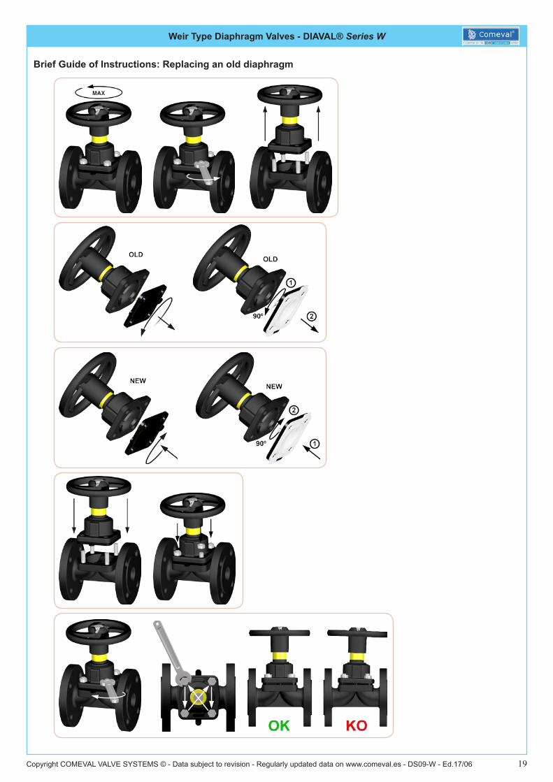
Brief Guide of Instructions: Replacing an old diaphragm

Weir Type Diaphragm Valves with Pneumatic Actuator- DIAVAL® Series with ARI-DP
Copyright COMEVAL VALVE SYSTEMS © - Data subject to revision - Regularly updated data on www.comeval.es - DS09-W - Ed.17/06 20
Main Features
● For DIAVAL manufactured valves in weir and straight through type, with rubber diaphragms and PTFE / rubber backed diaphragms.● Rugged & compact design, long life span at the plant. Favourable size / performance ratio.● Rolling diaphragm design, allowing long cycle operations.● Single acting (Direct and reverse actions).● High quality spring, large thrust.● Visual position indicator for open / close.● Burnished stem protected by bellow.● Maintenance-free O-ring sealing with flexible guiding.● Possibility of assembly of additional devices / accessories.● Operating ambient temperatures -40ºC to +100ºC.● Fully traceable at the manufacture facility, identified by aluminum riveted plates.● Optional top mounted emergency hand wheels for manual operation.● Compliant with Machinery Directive 2006/42/EC
Working Principle
Direct Acting actuator is designed to operate from a normally open position. Air pressure on the top side of actuator diaphragm closes the valve and the spring opens the valve when the air is released from the actuator.
Reverse Acting actuator is designed to operate from a normally closed position. Air pressure on the bottom side of the actuator diaphragm opens the valve. When air is released spring closes the valve.
DP Direct Acting DP Reverse Acting
Control Accesories
There is a number of control accessories available to be assembled on to the ARI actuators. These accessories are compre-hensive of limit switches (mechanical or inductive type), proximity sensors, solenoid valves, air speed regulators, positioners, air gauge sets… and many other customized solutions.Control accessories may be specified and provided by the customer or by DIAVAL, however, only those accessories installed and tested at any DIAVAL facilities are covered by a performance guarantee.
Tests - After Market
All actuators are tested after assembly and before dispatch. Tests are comprehensive of visual and functional tests as per EN-12266-1/DIN 3230 P.3 - EN.10.204/2.2Actuators can be serviced at DIAVAL facilities where a stock of common spares is permanently available. Off site service engineers are available on demand and against usual service rates.
Operating and Maintenance Instructions
Please ensure that the DIAVAL Operating and Maintenance Instructions are provided by your supplier along with the valves. Do not try to start maintenance without having read and understood the Essential Safety Guidelines. Please consult us for further information.
Weir Type Diaphragm Valves with Pneumatic Actuator

Weir Type Diaphragm Valves with Pneumatic Actuator- DIAVAL® Series with ARI-DP
Copyright COMEVAL VALVE SYSTEMS © - Data subject to revision - Regularly updated data on www.comeval.es - DS09-W - Ed.17/06 21
Standard Materials
Only the best quality materials are incorporated to the DIAVAL manufacturing process and are subject to a strict quality control by our DIAVAL engineers at the assembly plant.
DP Direct Acting
DP Reverse Acting
Top Handwheel (Optional)

Weir Type Diaphragm Valves with Pneumatic Actuator- DIAVAL® Series with ARI-DP
Copyright COMEVAL VALVE SYSTEMS © - Data subject to revision - Regularly updated data on www.comeval.es - DS09-W - Ed.17/06 22
Standard MaterialsPos. Description Material
1 Stem X20Cr13+QT, 1.4021+QT 2 Bellow seal EPDM50 or 42CR 3 Stem guiding * X20Cr13+QT, 1.4021+QT
3.1 Stem guiding * X20Cr13+QT, 1.4021+QT 3.2 Guiding band * PTFE + 25%C 3.3 O-ring (stem) * NBR 3.4 O-ring (guiding) * NBR 3.5 Scraper * NBR 4 Retaining ring FSt - A3B 5 Spring plate FSt (Fe/Zn12B)
6 / 7 Lower diaphragm casing (DP32-34Tri)
DD13+QT, 1.0335+QT (powder coated)
7 Lower diaphragm casing (DP35)
P265GH, 1.0425 / S235JR, 1.0037
8 Bushing X20Cr13+QT, 1.4021+QT
9 Diaphragm lange DD13+QT, 1.0335+QT (Fe/Zn12B) or X20Cr13+QT,
10 Rolling diaphragm * 1.4021+QT
11 Diaphragm plate (DP32-34Tri) NBR + webbing
11 Diaphragm plate (DP35) * DD13+QT, 1.0335+QT (Fe/Zn12B)
12 O-ring St 52-3 G 03 g, 1.0570 G 03 g
13 Bushing NBR 14 Flange nut X20Cr13+QT, 1.4021+QT 15 Compression spring * 8 - A4G 16 Spring centring FDSiCr 17 Spring centring DC01, 1.0330 (Fe/Zn12B)
18 Upper diaphragm casing (DP32-34Tri)
St 52-3 G 03 g, 1.0570 G 03 g
18 Upper diaphragm casing (DP35)
DD13+QT, 1.0335+QT (powder coated)
19 Screwed cap P265GH, 1.0425 / S235JR, 1.0037
20 Hexagon nut (DP32-34Tri) 1) Polyäthylen
20 Hexagon nut (DP35) 1) 8 - A4G
Pos. Description Material
21 Hexagon screw (DP32-34Tri) 1) C35E, 1.1181
21 Hexagon screw (DP35) 1) 8.8 - A4G
22 Washer 8.8 - A4G
23 Hexagon screw (DP32-34Tri) 1) St - A4G
23 Hexagon screw (DP35) 1) 8.8 - A4G 24 Eye nut 1) 10.9 - A2G 34 Stem extension 8-A4G
36.1 Bellow seal * X20Cr13+QT, 1.4021+QT
36.2 Guiding band * X14CrMoS17+QT, 1.4104+QT
36.3 O-ring * PTFE +25%C 36.4 O-ring * NBR 36.5 Scraper * NBR 37 Bushing NBR38 Hexagon screw X20Cr13+QT, 1.4021+QT39 Washer 8.8 - A4G42 Torsion lock X20Cr13+QT, 1.4021+QT
44 1 Distance column 8.8 - A4G
47 Stem 1SMn30+C, 1.0715+C (Fe/Zn12B)
48 Traverse X20Cr13+QT, 1.4021+QT
50 Axial-washer EN-JS1049, EN-GJS-400-18U-LT (Fe/Zn12B)
51 Axial-dial ring St52 Threaded bush St
53 Catch pin CuZn35Ni3Mn2Al-Pb-R490, CW710RR490
54 Lubricating nipple St, Cu55 Covering for traverse 5.8 - A4G
58 Handwheel S235JR, 1.0037 (Fe/Zn12B)
59 Safety cap Fe P01, 1.0330 (epoxy coating)

Weir Type Diaphragm Valves with Pneumatic Actuator- DIAVAL® Series with ARI-DP
Copyright COMEVAL VALVE SYSTEMS © - Data subject to revision - Regularly updated data on www.comeval.es - DS09-W - Ed.17/06 23
Information / restriction of technical rules need to be observed!Installation, Operating and Maintenance Manual can be downloaded at www.comeval.es
The engineer, designing a system or a plant, is responsable for the selection of the correct valveProduct suitability must be verified, contact manufacturer for information
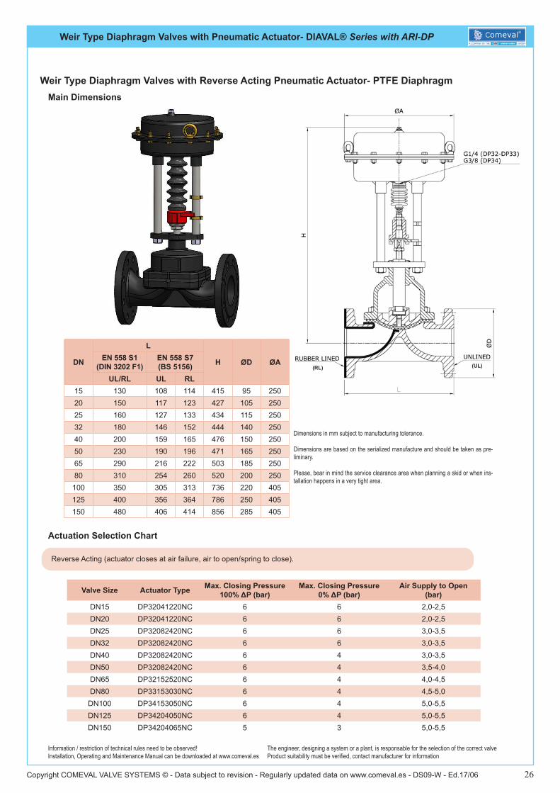
Dimensions in mm subject to manufacturing tolerance.
Dimensions are based on the serialized manufacture and should be taken as pre-liminary.
Please, bear in mind the service clearance area when planning a skid or when ins-tallation happens in a very tight area.
DN
L
H ØD ØAEN 558 S1 (DIN 3202 F1)
EN 558 S7(BS 5156)
UL/RL UL RL15 130 108 114 415 95 25020 150 117 123 427 105 25025 160 127 133 434 115 25032 180 146 152 444 140 25040 200 159 165 476 150 25050 230 190 196 471 165 25065 290 216 222 503 185 25080 310 254 260 520 200 250
100 350 305 313 736 220 405125 400 356 364 786 250 405150 480 406 414 856 285 405
Weir Type Diaphragm Valves with Direct Acting Pneumatic Actuator- Rubber DiaphragmMain Dimensions
Direct Acting (actuator opens at air failure, springs to open/air to close).
Valve Size Actuator Type Max. Closing Pressure 100% ΔP (bar)
Max. Closing Pressure 0% ΔP (bar)
Air Supply to Close (bar)
DN15 DP32021020NA 10 10 1,5-2,0DN20 DP32021020NA 10 10 1,5-2,0DN25 DP32021020NA 10 10 2,0-2,5DN32 DP32021020NA 10 10 2,0-2,5DN40 DP32021020NA 10 10 2,0-2,5DN50 DP32021020NA 10 10 2,0-2,5DN65 DP32021020NA 8 8 3,0-3,5DN80 DP32021030NA 8 8 3,5-4,0
DN100 DP34021050NA 8 8 2,5-3,5DN125 DP34021050NA 8 8 3,5-4,5DN150 DP34021065NA 6 6 4,0-5,0
Actuation Selection Chart
(RL) (UL)

Weir Type Diaphragm Valves with Pneumatic Actuator- DIAVAL® Series with ARI-DP
Copyright COMEVAL VALVE SYSTEMS © - Data subject to revision - Regularly updated data on www.comeval.es - DS09-W - Ed.17/06 24
Information / restriction of technical rules need to be observed!Installation, Operating and Maintenance Manual can be downloaded at www.comeval.es
The engineer, designing a system or a plant, is responsable for the selection of the correct valveProduct suitability must be verified, contact manufacturer for information
Dimensions in mm subject to manufacturing tolerance.
Dimensions are based on the serialized manufacture and should be taken as pre-liminary.
Please, bear in mind the service clearance area when planning a skid or when ins-tallation happens in a very tight area.
DN
L
H ØD ØAEN 558 S1 (DIN 3202 F1)
EN 558 S7(BS 5156)
UL/RL UL RL15 130 108 114 415 95 25020 150 117 123 427 105 25025 160 127 133 434 115 25032 180 146 152 444 140 25040 200 159 165 476 150 25050 230 190 196 471 165 25065 290 216 222 503 185 25080 310 254 260 520 200 250
100 350 305 313 736 220 405125 400 356 364 786 250 405150 480 406 414 856 285 405
Weir Type Diaphragm Valves with Reverse Acting Pneumatic Actuator- Rubber DiaphragmMain Dimensions
Reverse Acting (actuator closes at air failure, air to open/spring to close).
Valve Size Actuator Type Max. Closing Pressure 100% ΔP (bar)
Max. Closing Pressure 0% ΔP (bar)
Air Supply to Open (bar)
DN15 DP32041220NC 10 9 2,0-2,5DN20 DP32041220NC 10 9 2,0-2,5DN25 DP32082420NC 10 9 3,0-3,5DN32 DP32082420NC 10 9 3,0-3,5DN40 DP32082420NC 9 7 3,0-3,5DN50 DP32082420NC 8 6 3,0-3,5DN65 DP32152520NC 8 6 3,0-3,5DN80 DP33153030NC 8 6 4,0-4,5
DN100 DP34153050NC 8 6 4,0-4,5DN125 DP34204050NC 7 4 5,0-5,5DN150 DP34204065NC 6 3 5,0-5,5
Actuation Selection Chart
(RL) (UL)

Weir Type Diaphragm Valves with Pneumatic Actuator- DIAVAL® Series with ARI-DP
Copyright COMEVAL VALVE SYSTEMS © - Data subject to revision - Regularly updated data on www.comeval.es - DS09-W - Ed.17/06 25
Information / restriction of technical rules need to be observed!Installation, Operating and Maintenance Manual can be downloaded at www.comeval.es
The engineer, designing a system or a plant, is responsable for the selection of the correct valveProduct suitability must be verified, contact manufacturer for information
Dimensions in mm subject to manufacturing tolerance.
Dimensions are based on the serialized manufacture and should be taken as pre-liminary.
Please, bear in mind the service clearance area when planning a skid or when ins-tallation happens in a very tight area.
DN
L
H ØD ØAEN 558 S1 (DIN 3202 F1)
EN 558 S7(BS 5156)
UL/RL UL RL15 130 108 114 415 95 25020 150 117 123 427 105 25025 160 127 133 434 115 25032 180 146 152 444 140 25040 200 159 165 476 150 25050 230 190 196 471 165 25065 290 216 222 503 185 25080 310 254 260 520 200 250
100 350 305 313 736 220 405125 400 356 364 786 250 405150 480 406 414 856 285 405
Weir Type Diaphragm Valves with Direct Acting Pneumatic Actuator- PTFE DiaphragmMain Dimensions
Direct Acting (actuator opens at air failure, springs to open/air to close).
Valve Size Actuator Type Max. Closing Pressure 100% ΔP (bar)
Max. Closing Pressure 0% ΔP (bar)
Air Supply to Close (bar)
DN15 DP32021020NA 6 6 2,0-2,5DN20 DP32021020NA 6 6 2,0-2,5DN25 DP32021020NA 6 6 2,5-3,0DN32 DP32021020NA 6 6 2,5-3,0DN40 DP32021020NA 6 6 3,0-3,5DN50 DP32021020NA 6 6 3,5-4,0DN65 DP32021020NA 6 5 4,5-5,0DN80 DP32021030NA 6 4 5,0-5,5
DN100 DP34021050NA 6 4 4,5-5,0DN125 DP34021065NA 6 4 4,5-5,0DN150 DP34021065NA 5 3 5,0-5,5
Actuation Selection Chart
(RL) (UL)
Weir Type Diaphragm Valves with Pneumatic Actuator- DIAVAL® Series with ARI-DP
Copyright COMEVAL VALVE SYSTEMS © - Data subject to revision - Regularly updated data on www.comeval.es - DS09-W - Ed.17/06 26
Information / restriction of technical rules need to be observed!Installation, Operating and Maintenance Manual can be downloaded at www.comeval.es
The engineer, designing a system or a plant, is responsable for the selection of the correct valveProduct suitability must be verified, contact manufacturer for information
Dimensions in mm subject to manufacturing tolerance.
Dimensions are based on the serialized manufacture and should be taken as pre-liminary.
Please, bear in mind the service clearance area when planning a skid or when ins-tallation happens in a very tight area.
DN
L
H ØD ØAEN 558 S1 (DIN 3202 F1)
EN 558 S7(BS 5156)
UL/RL UL RL15 130 108 114 415 95 25020 150 117 123 427 105 25025 160 127 133 434 115 25032 180 146 152 444 140 25040 200 159 165 476 150 25050 230 190 196 471 165 25065 290 216 222 503 185 25080 310 254 260 520 200 250
100 350 305 313 736 220 405125 400 356 364 786 250 405150 480 406 414 856 285 405
Weir Type Diaphragm Valves with Reverse Acting Pneumatic Actuator- PTFE DiaphragmMain Dimensions
Reverse Acting (actuator closes at air failure, air to open/spring to close).
Valve Size Actuator Type Max. Closing Pressure 100% ΔP (bar)
Max. Closing Pressure 0% ΔP (bar)
Air Supply to Open (bar)
DN15 DP32041220NC 6 6 2,0-2,5DN20 DP32041220NC 6 6 2,0-2,5DN25 DP32082420NC 6 6 3,0-3,5DN32 DP32082420NC 6 6 3,0-3,5DN40 DP32082420NC 6 4 3,0-3,5DN50 DP32082420NC 6 4 3,5-4,0DN65 DP32152520NC 6 4 4,0-4,5DN80 DP33153030NC 6 4 4,5-5,0
DN100 DP34153050NC 6 4 5,0-5,5DN125 DP34204050NC 6 4 5,0-5,5DN150 DP34204065NC 5 3 5,0-5,5
Actuation Selection Chart
(RL) (UL)
Weir Type Diaphragm Valves with Piston Pneumatic Actuator- DIAVAL® Series
Copyright COMEVAL VALVE SYSTEMS © - Data subject to revision - Regularly updated data on www.comeval.es - DS09-W - Ed.17/06 27
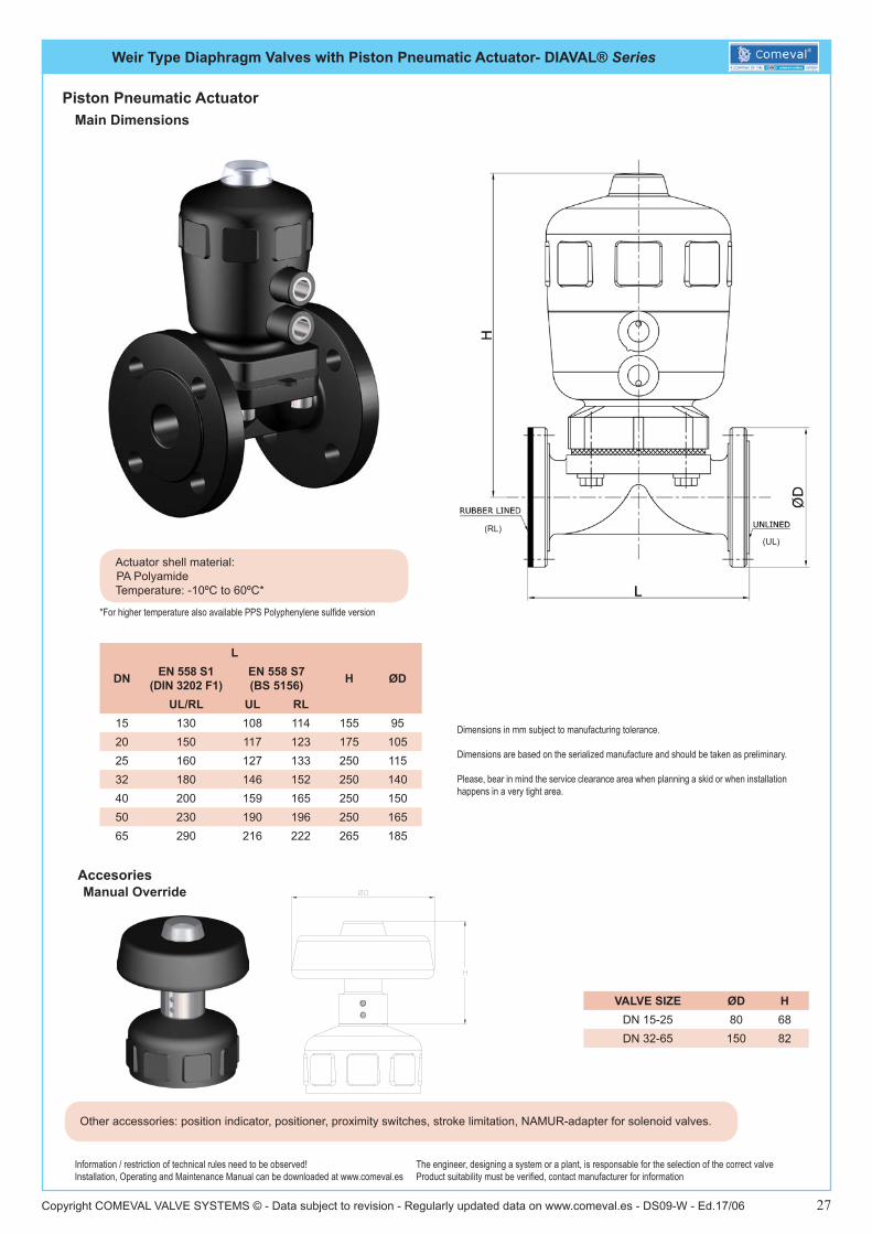
Information / restriction of technical rules need to be observed!Installation, Operating and Maintenance Manual can be downloaded at www.comeval.es
The engineer, designing a system or a plant, is responsable for the selection of the correct valveProduct suitability must be verified, contact manufacturer for information
Dimensions in mm subject to manufacturing tolerance.
Dimensions are based on the serialized manufacture and should be taken as preliminary.
Please, bear in mind the service clearance area when planning a skid or when installation happens in a very tight area.
DN
L
H ØDEN 558 S1 (DIN 3202 F1)
EN 558 S7(BS 5156)
UL/RL UL RL15 130 108 114 155 9520 150 117 123 175 10525 160 127 133 250 11532 180 146 152 250 14040 200 159 165 250 15050 230 190 196 250 16565 290 216 222 265 185
Main Dimensions
Other accessories: position indicator, positioner, proximity switches, stroke limitation, NAMUR-adapter for solenoid valves.
Accesories
VALVE SIZE ØD HDN 15-25 80 68DN 32-65 150 82
Manual Override
(RL)(UL)
Piston Pneumatic Actuator
Actuator shell material: PA Polyamide
Temperature: -10ºC to 60ºC*
*For higher temperature also available PPS Polyphenylene sulfide version
Weir Type Diaphragm Valves with Piston Pneumatic Actuator- DIAVAL® Series
Copyright COMEVAL VALVE SYSTEMS © - Data subject to revision - Regularly updated data on www.comeval.es - DS09-W - Ed.17/06 28
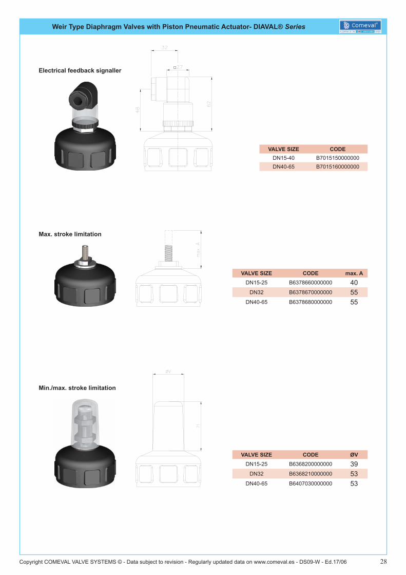
VALVE SIZE CODEDN15-40 B7015150000000DN40-65 B7015160000000
VALVE SIZE CODE max. ADN15-25 B6378660000000 40
DN32 B6378670000000 55DN40-65 B6378680000000 55
VALVE SIZE CODE ØVDN15-25 B6368200000000 39
DN32 B6368210000000 53DN40-65 B6407030000000 53
Electrical feedback signaller
Max. stroke limitation
Min./max. stroke limitation

Weir Type Diaphragm Valves with Piston Pneumatic Actuator- DIAVAL® Series
Copyright COMEVAL VALVE SYSTEMS © - Data subject to revision - Regularly updated data on www.comeval.es - DS09-W - Ed.17/06 29
VALVE SIZE CODEDN15-25 B6822640000000DN32-65 B6822650000000
VALVE SIZE CODEDN15 B2FCINME3MP050DN20 B2FCINME3MP063DN25 B2FCINME3MP080DN32 B2FCINME3MP100DN40 B2FCINME3MP100DN50 B2FCINME3MP100DN65 B2FCINME3MP125
VALVE SIZE CODE A BDN20-32 B6371130000000 46 24DN40-65 B6371140000000 58 30
Electrical position feedback
External magnetic inductive position feedback
Namur-adapter for pilot valves
Weir Type Diaphragm Valves with Piston Pneumatic Actuator- DIAVAL® Series
Copyright COMEVAL VALVE SYSTEMS © - Data subject to revision - Regularly updated data on www.comeval.es - DS09-W - Ed.17/06 30
Information / restriction of technical rules need to be observed!Installation, Operating and Maintenance Manual can be downloaded at www.comeval.es
The engineer, designing a system or a plant, is responsable for the selection of the correct valveProduct suitability must be verified, contact manufacturer for information
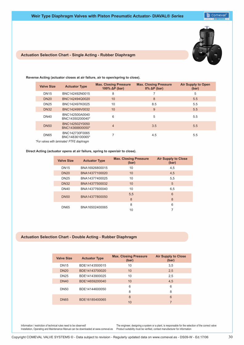
Reverse Acting (actuator closes at air failure, air to open/spring to close).
Valve Size Actuator Type Max. Closing Pressure 100% ΔP (bar)
Max. Closing Pressure 0% ΔP (bar)
Air Supply to Open (bar)
DN15 BNC142492N0015 8 7 5DN20 BNC142494Q0020 10 8 5.5DN25 BNC142497K0025 10 8.5 5.5DN32 BNC142499V0032 10 9 5.5
DN40 BNC142500A0040BNC14350200040* 6 5 5.5
DN50 BNC142502Y0050BNC14368800050* 4 3.5 5.5
DN65 BNC142730F0065BNC14836100065* 7 4.5 5.5
Actuation Selection Chart - Single Acting - Rubber Diaphragm
Direct Acting (actuator opens at air failure, spring to open/air to close).
Valve Size Actuator Type Max. Closing Pressure (bar)
Air Supply to Close (bar)
DN15 BNA16926800015 10 4,5DN20 BNA14377100020 10 4,5DN25 BNA14377400025 10 5,5DN32 BNA14377500032 10 5DN40 BNA14377600040 10 6,5
DN50 BNA143778000505,5 68 8
DN65 BNA165024000658 610 7
Valve Size Actuator Type Max. Closing Pressure (bar)
Air Supply to Close (bar)
DN15 BDE14143500015 10 3,5DN20 BDE14143700020 10 2,5DN25 BDE14143900025 10 2,5DN40 BDE14659200040 10 4,5
DN50 BDE141446000506 68 8
DN65 BDE161854000658 610 7
Actuation Selection Chart - Double Acting - Rubber Diaphragm
*For valves with laminated PTFE diaphragm
Weir Type Diaphragm Valves - DIAVAL® Series W
Copyright COMEVAL VALVE SYSTEMS © - Data subject to revision - Regularly updated data on www.comeval.es - DS09-W - Ed.17/06 31
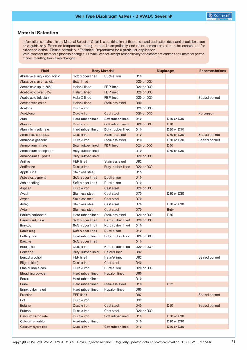
Material Selection
Fluid Body Material Diaphragm RecomendationsAbrasive slurry - non acidic Soft rubber lined Ductile iron D10Abrasive slurry - acidic Butyl lined D20 or D30Acetic acid up to 50% Halar® lined FEP lined D20 or D30Acetic acid over 50% Halar® lined FEP lined D20 or D30Acetic acid (glacial) Halar® lined FEP lined D20 or D30 Sealed bonnetAcetoacetic ester Halar® lined Stainless steel D90Acetone Ductile iron D20 or D30Acetylene Ductile iron Cast steel D20 or D30 No copperAlum Hard rubber lined Soft rubber lined D10 D20 or D30Alumina Ductile iron Soft rubber lined D20 or D30 D10Aluminium sulphate Hard rubber lined Butyl rubber lined D10 D20 or D30Ammonia, aqueous Ductile iron Stainless steel D10 D20 or D30 Sealed bonnetAmmonia gaseous Ductile iron Stainless steel D10 D20 or D30 Sealed bonnetAmmonium nitrate Butyl rubber lined FEP lined D20 or D30 D50Ammonium phosphate Butyl rubber lined D10 D20 or D30Ammonium sulphate Butyl rubber lined D20 or D30Aniline FEP lined Stainless steel D92Antifreeze Ductile iron Butyl rubber lined D20 or D30Apple juice Stainless steel D15Asbestos cement Soft rubber lined Ductile iron D10Ash handling Soft rubber lined Ductile iron D10Asphalt Ductile iron Cast steel D20 or D30Avcat Stainless steel Cast steel D70 D20 or D30Avgas Stainless steel Cast steel D70Avtag Stainless steel Cast steel D70 D20 or D30Avtur Stainless steel Cast steel D70 ButylBarium carbonate Hard rubber lined Stainless steel D20 or D30 D50Barium sulphate Soft rubber lined Hard rubber lined D20 or D30Barytes Soft rubber lined Hard rubber lined D10Basic slag Soft rubber lined Ductile iron D10Battery acid Hard rubber lined Butyl rubber lined D20 or D30Bauxite Soft rubber lined D10Beet juice Ductile iron Hard rubber lined D20 or D30Benzene Butyl rubber lined Halar® lined D92Benzyl alcohol FEP lined Halar® lined D92 Sealed bonnetBilge (ships) Ductile iron Cast steel D40Blast furnace gas Ductile iron Ductile iron D20 or D30Bleaching powder Hard rubber lined Hypalon lined D60Borax Hard rubber lined D10Brine Hard rubber lined Stainless steel D10 D92Brine, chlorinated Hard rubber lined Hypalon lined D60Bromine FEP lined D92 Sealed bonnetBcf Ductile iron D92Butane Ductile iron Cast steel D40 D50 Sealed bonnetButanol Ductile iron Cast steel D20 or D30Calcium carbonate Ductile iron Soft rubber lined D10 D20 or D30Calcium chloride Hard rubber lined D10 D20 or D30Calcium hydroxide Ductile iron Soft rubber lined D10 D20 or D30
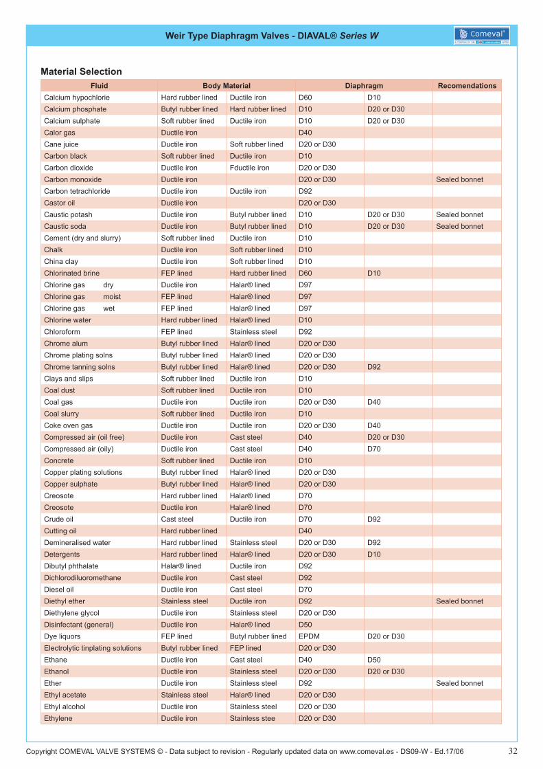
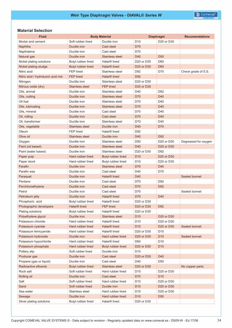
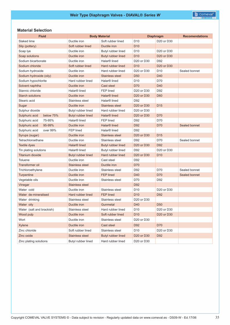
Information contained in the Material Selection Chart is a combination of theoretical and application data, and should be taken as a guide only. Pressure-temperature rating, material compatibility and other parameters also to be considered for rubber selection. Please consult our Technical Department for a particular application.With constant material / process changes, Diaval® cannot accept responsibility for diaphragm and/or body material perfor-mance resulting from such changes.
Weir Type Diaphragm Valves - DIAVAL® Series W
Copyright COMEVAL VALVE SYSTEMS © - Data subject to revision - Regularly updated data on www.comeval.es - DS09-W - Ed.17/06 32
Material SelectionFluid Body Material Diaphragm Recomendations
Calcium hypochlorie Hard rubber lined Ductile iron D60 D10Calcium phosphate Butyl rubber lined Hard rubber lined D10 D20 or D30Calcium sulphate Soft rubber lined Ductile iron D10 D20 or D30Calor gas Ductile iron D40Cane juice Ductile iron Soft rubber lined D20 or D30Carbon black Soft rubber lined Ductile iron D10Carbon dioxide Ductile iron Fductile iron D20 or D30Carbon monoxide Ductile iron D20 or D30 Sealed bonnetCarbon tetrachloride Ductile iron Ductile iron D92Castor oil Ductile iron D20 or D30Caustic potash Ductile iron Butyl rubber lined D10 D20 or D30 Sealed bonnetCaustic soda Ductile iron Butyl rubber lined D10 D20 or D30 Sealed bonnetCement (dry and slurry) Soft rubber lined Ductile iron D10Chalk Ductile iron Soft rubber lined D10China clay Ductile iron Soft rubber lined D10Chlorinated brine FEP lined Hard rubber lined D60 D10Chlorine gas dry Ductile iron Halar® lined D97Chlorine gas moist FEP lined Halar® lined D97Chlorine gas wet FEP lined Halar® lined D97Chlorine water Hard rubber lined Halar® lined D10Chloroform FEP lined Stainless steel D92Chrome alum Butyl rubber lined Halar® lined D20 or D30Chrome plating solns Butyl rubber lined Halar® lined D20 or D30Chrome tanning solns Butyl rubber lined Halar® lined D20 or D30 D92Clays and slips Soft rubber lined Ductile iron D10Coal dust Soft rubber lined Ductile iron D10Coal gas Ductile iron Ductile iron D20 or D30 D40Coal slurry Soft rubber lined Ductile iron D10Coke oven gas Ductile iron Ductile iron D20 or D30 D40Compressed air (oil free) Ductile iron Cast steel D40 D20 or D30Compressed air (oily) Ductile iron Cast steel D40 D70Concrete Soft rubber lined Ductile iron D10Copper plating solutions Butyl rubber lined Halar® lined D20 or D30Copper sulphate Butyl rubber lined Halar® lined D20 or D30Creosote Hard rubber lined Halar® lined D70Creosote Ductile iron Halar® lined D70Crude oil Cast steel Ductile iron D70 D92Cutting oil Hard rubber lined D40Demineralised water Hard rubber lined Stainless steel D20 or D30 D92Detergents Hard rubber lined Halar® lined D20 or D30 D10Dibutyl phthalate Halar® lined Ductile iron D92Dichlorodiluoromethane Ductile iron Cast steel D92Diesel oil Ductile iron Cast steel D70Diethyl ether Stainless steel Ductile iron D92 Sealed bonnetDiethylene glycol Ductile iron Stainless steel D20 or D30Disinfectant (general) Ductile iron Halar® lined D50Dye liquors FEP lined Butyl rubber lined EPDM D20 or D30Electrolytic tinplating solutions Butyl rubber lined FEP lined D20 or D30Ethane Ductile iron Cast steel D40 D50Ethanol Ductile iron Stainless steel D20 or D30 D20 or D30Ether Ductile iron Stainless steel D92 Sealed bonnetEthyl acetate Stainless steel Halar® lined D20 or D30Ethyl alcohol Ductile iron Stainless steel D20 or D30Ethylene Ductile iron Stainless stee D20 or D30

Weir Type Diaphragm Valves - DIAVAL® Series W
Copyright COMEVAL VALVE SYSTEMS © - Data subject to revision - Regularly updated data on www.comeval.es - DS09-W - Ed.17/06 33
Material SelectionFluid Body Material Diaphragm Recomendations
Ethylene glycol Ductile iron Stainless steel D20 or D30Ferric sulphate Butyl rubber lined Halar® lined D10Fetilizers (dry powders) Soft rubber lined Ductile iron D10Fertilizer slurries (wet process) Butyl rubber lined Ductile iron D20 or D30 D20 or D30Fire foam Ductile iron Cast steel D40Flue gas Ductile iron Cast steel D40 D20 or D30Fly ash Ductile iron Soft rubber lined D10 ButylFreon Ductile iron Ductile iron D92 D50Fuel oil Ductile iron Cast steel D40Gas (coal) Ductile iron Cast steel D40Gas (natural Ductile iron Cast steel D40Gasoline Cast steel Ductile iron D70Glucose Stainless steel Stainless steel D20 or D30Glycerine Stainless steel Hard rubber lined D20 or D30Gravel Soft rubber lined Ductile iron D10Grease Ductile iron Cast steel D40Gypsum Soft rubber lined Ductile iron D10Hydraulic oils (vegetable based) Ductile iron Ductile iron D20 or D30Hydraulic oils (mineral based) Ductile iron Ductile iron D40Hydrobromic acid FEP lined Halar® lined D92Hydrochloric acid Hard rubber lined Halar® lined D10 D92Hydroluoric acid Butyl rubber lined Halar® lined D20 or D30Hydrogen Ductile iron Cast steel D20 or D30 D10 Sealed bonnetHydrogen peroxide Hard rubber lined Stainless steel PTFE/D70 D20 or D30Hypo Hard rubber lined Halar® lined D10 D60Inert gases Ductile iron Ductile iron D20 or D30Inks Stainless steel Halar® lined D92 D20 or D30Insecticide solutions Ductile iron Ductile iron D40 D20 or D30Instrument air Ductile iron Stainless steel D20 or D30 D40Iron oxide slurry Soft rubber lined Ductile iron D20 or D30Isopropanol Ductile iron Hard rubber lined D10 D20 or D30Kaolin Soft rubber lined Ductile iron D10Kerosene Ductile iron Stainless steel D70 D92Laundry bleach Hard rubber lined Halar® lined D60 D10Lime Ductile iron Soft rubber line D10Liquid parafin Ductile iron Ductile iron D40 D70Liquid petroleum gases (l.P.G.) Ductile iron Cast steel D40 D20 or D30 Sealed bonnetLubricating oils Hard rubber lined Cast steel D40 D70Magnesium chloride Ductile iron Butyl rubber lined D10 D20 or D30Magnesium oxide Butyl rubber lined Hard rubber line D10 D20 or D30Magnesium sulphate Soft rubber lined Ductile iron D10 D20 or D30Magnetite Hard rubber lined Ductile iron D10Methane Ductile iron Ductile iron D20 or D30 D40Methanol Ductile iron Stainless steel D20 or D30Methanol/water mixture Ductile iron Hard rubber lined D20 or D30 D10Methylated spirits Ductile iron Stainless steel D20 or D30Methyl ethyl ketone (mek) Stainless steel FEP lined D92Methyl isobutyl ketone Stainless steel FEP lined D92 D20 or D30Milk Stainless steel D15Mineral oil Ductile iron Cast steel D70 D40Molasses Ductile iron Stainless steel D20 or D30Monosodium glutamate Hard rubber lined Stainless steel D10
Weir Type Diaphragm Valves - DIAVAL® Series W
Copyright COMEVAL VALVE SYSTEMS © - Data subject to revision - Regularly updated data on www.comeval.es - DS09-W - Ed.17/06 34
Material SelectionFluid Body Material Diaphragm Recomendations
Mortar and cement Soft rubber lined Ductile iron D10 D20 or D30Naphtha Ductile iron Cast steel D70Napthalene Ductile iron Cast steel D70Natural gas Ductile iron Stainless steel D40 D50Nickel plating solutions Butyl rubber lined Halar® lined D20 or D30 D60Nickel plating sludge Butyl rubber lined Halar® lined D20 or D30 D60Nitric acid FEP lined Stainless steel D92 D70 Check grade of S.S.Nitric acid / hydroluoric acid mix FEP lined Halar® lined D92Nitrogen Ductile iron Stainless steel D20 or D30Nitrous oxide (dry) Stainless steel FEP lined D20 or D30Oils, animal Ductile iron Stainless steel D40 D92Oils, cutting Ductile iron Stainless steel D70 D40Oil fuel Ductile iron Stainless steel D70 D40Oils, lubricating Ductile iron Stainless steel D70 D40Oils, mineral Ductile iron Cast steel D70 D40Oil, rolling Ductile iron Cast steel D70 D40Oil, transformer Ductile iron Stainless steel D70 D40Oils, vegetable Stainless steel Ductile iron D40 D70Oleum FEP lined Halar® lined D92 Olive oil Stainless steel Ductile iron D40 D92Oxygen Ductile iron Stainless steel D50 D20 or D30 Degreased for oxygenPaint (oil based) Ductile iron Stainless steel D40 D20 or D30Paint (water based) Ductile iron Stainless steel D20 or D30 D92Paper pulp Hard rubber lined Butyl rubber lined D10 D20 or D30Paper stock Hard rubber lined Butyl rubber lined D10 D20 or D30Parafin Ductile iron Stainless steel D70 D40Parafin wax Ductile iron Cast steel D40 D70Paraquet Ductile iron Halar® lined D40 Sealed bonnetPentane Ductile iron Cast steel D70 D92Perchloroethylene Ductile iron Cast steel D70 D92Petrol Ductile iron Cast steel D70 Sealed bonnetPetroleum jelly Ductile iron Halar® lined D70 D40Phosphoric acid Butyl rubber lined Halar® lined D20 or D30 Photographic developers Halar® lined FEP lined D20 or D30 D92Plating solutions Butyl rubber lined Halar® lined D20 or D30 Polyethylene glycol Ductile iron Stainless steel D10 D20 or D30Potassium chloride Hard rubber lined Halar® lined D10 D20 or D30Potassium cyanide Hard rubber lined Halar® lined D10 D20 or D30 Sealed bonnetPotassium ferricyanide Hard rubber lined Halar® lined D20 or D30 D10Potassium hydroxide Ductile iron Hard rubber lined D20 or D30 D10 Sealed bonnetPotassium hypochlorite Hard rubber lined Halar® lined D60 D10Potassium phosphate Hard rubber lined Butyl rubber lined D20 or D30 D10Pottery slip Soft rubber lined Ductile iron D10 Producer gas Ductile iron Cast steel D20 or D30 D40Propane (gas or liquid) Ductile iron Cast steel D40 D50Radioactive efluents Butyl rubber lined Stainless steel D20 or D30 No copper parts.Rock salt Soft rubber lined Hard rubber lined D10 D20 or D30Rolling oil Ductile iron Cast steel D70 D10Salt Soft rubber lined Hard rubber lined D10 D20 or D30Sand Soft rubber lined Ductile iron D10 D20 or D30Sea water Stainless steel Hard rubber lined D10 D20 or D30Sewage Ductile iron Hard rubber lined D10 D50Silver plating solutions Butyl rubber lined Halar® lined D20 or D30
Weir Type Diaphragm Valves - DIAVAL® Series W
Copyright COMEVAL VALVE SYSTEMS © - Data subject to revision - Regularly updated data on www.comeval.es - DS09-W - Ed.17/06 35
Material SelectionFluid Body Material Diaphragm Recomendations
Slaked lime Ductile iron Soft rubber lined D10 D20 or D30Slip (pottery) Soft rubber lined Ductile iron D10Soap lye Ductile iron Butyl rubber lined D10 D20 or D30Soap solutions Ductile iron Butyl rubber lined D10 D20 or D30Sodium bicarbonate Ductile iron Halar® lined D20 or D30 D92Sodium chloride Soft rubber lined Hard rubber lined D10 D20 or D30Sodium hydroxide Ductile iron Hard rubber lined D20 or D30 D10 Sealed bonnetSodium hydroxide (oily) Ductile iron Stainless steel D50 D40Sodium hypochlorite Hard rubber lined Halar® lined D10 D70Solvent naphtha Ductile iron Cast steel D70 D40Stannic chloride Halar® lined FEP lined D20 or D30 D92Starch solutions Ductile iron Halar® lined D20 or D30 D60Stearic acid Stainless steel Halar® lined D92Sugar Ductile iron Stainless steel D20 or D30 D15Sulphur dioxide Butyl rubber lined Hard rubber lined D20 or D30Sulphuric acid below 75% Butyl rubber lined Halar® lined D20 or D30 D70Sulphuric acid 75-95% Halar® lined FEP lined D92 D70Sulphuric acid 95-99% Ductile iron Halar® lined D92 D70 Sealed bonnetSulphuric acid over 99% FEP lined Halar® lined D92Syrups (sugar) Ductile iron Stainless steel D20 or D30 D15Tetrachloroethane Ductile iron Stainless steel D92 D70 Sealed bonnetTextile dyes Halar® lined Butyl rubber lined D20 or D30 D92Tin plating solutions Halar® lined Butyl rubber lined D92 D20 or D30Titanium dioxide Butyl rubber lined Hard rubber lined D20 or D30 D10Toluene Ductile iron Cast steel D92Transformer oil Stainless steel Ductile iron D70Trichloroethylene Ductile iron Stainless steel D92 D70 Sealed bonnetTurpentine Ductile iron FEP lined D40 D70 Sealed bonnetVegetable oils Ductile iron Stainless steel D70 D92Vinegar Stainless steel D92Water cold Ductile iron Stainless steel D10 D20 or D30Water de-mineralised Hard rubber lined FEP lined D10 D92Water drinking Stainless steel Stainless steel D20 or D30Water oily Ductile iron Gunmetal D40 D50Water (salt and brackish) Stainless steel Hard rubber lined D10 D20 or D30Wood pulp Ductile iron Soft rubber lined D10 D20 or D30
Wort Ductile iron Stainless steel D20 or D30
Xylene Ductile iron Cast steel D92 D70
Zinc chloride Soft rubber lined Stainless steel D10 D20 or D30
Zinc oxide Stainless steel Butyl rubber lined D20 or D30 D92
Zinc plating solutions Butyl rubber lined Hard rubber lined D20 or D30

www.diaval.com
Diaval®New Horizons in theProcess Industry.