diaphragm liquid pump nf 100 - custom pumps … liquid pump nf 100 about this document knf flodos...
TRANSCRIPT
KNF Flodos BA_NF100_EN_04_067676 Translation of original Operating and Installation Instructions Keep for future reference!
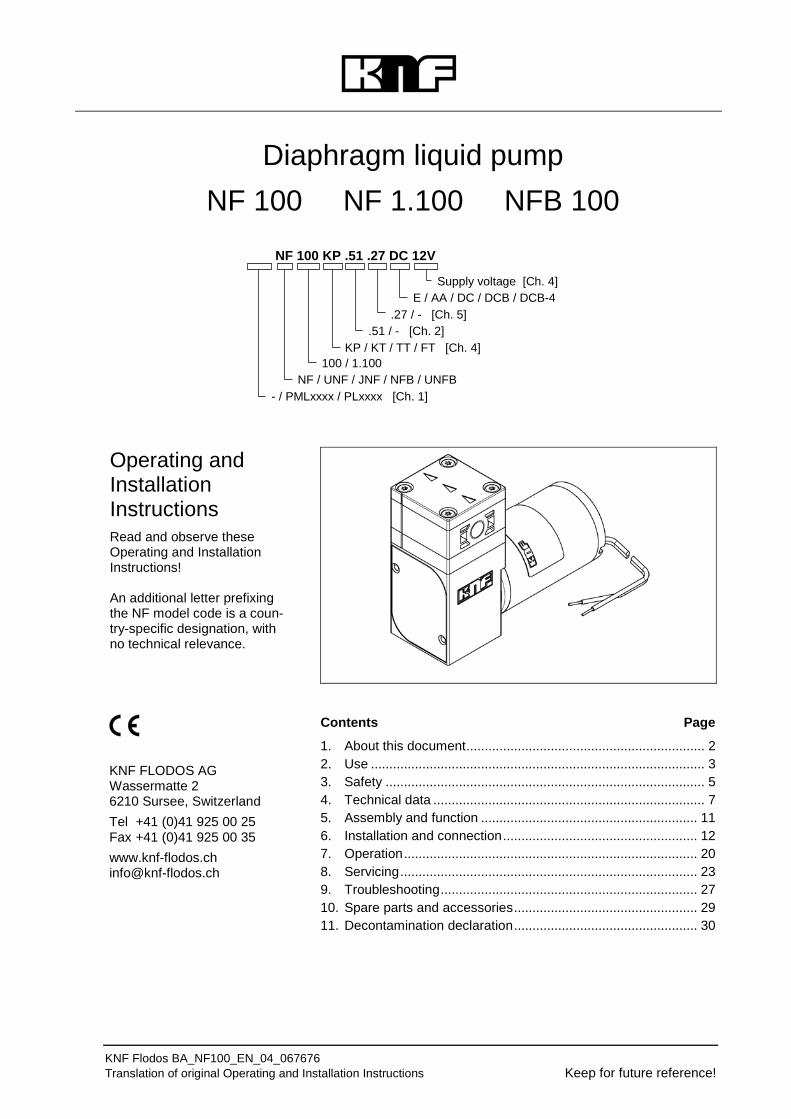
Diaphragm liquid pump NF 100 NF 1.100 NFB 100
Operating and Installation Instructions Read and observe these Operating and Installation Instructions! An additional letter prefixing the NF model code is a coun-try-specific designation, with no technical relevance.
Contents Page
1. About this document ................................................................. 2 2. Use ........................................................................................... 3 3. Safety ....................................................................................... 5 4. Technical data .......................................................................... 7 5. Assembly and function ........................................................... 11 6. Installation and connection ..................................................... 12 7. Operation ................................................................................ 20 8. Servicing ................................................................................. 23 9. Troubleshooting ...................................................................... 27 10. Spare parts and accessories .................................................. 29 11. Decontamination declaration .................................................. 30
KNF FLODOS AG Wassermatte 2 6210 Sursee, Switzerland Tel +41 (0)41 925 00 25 Fax +41 (0)41 925 00 35 www.knf-flodos.ch [email protected]
NF 100 KP .51 .27 DC 12V
E / AA / DC / DCB / DCB-4
.51 / - [Ch. 2] KP / KT / TT / FT [Ch. 4]
NF / UNF / JNF / NFB / UNFB
Supply voltage [Ch. 4]
100 / 1.100
- / PMLxxxx / PLxxxx [Ch. 1]
.27 / - [Ch. 5]

Diaphragm liquid pump NF 100 About this document
KNF Flodos BA_NF100_EN_04_067676 Translation of original Operating and Installation Instructions 2
1. About this document 1.1. Use of the Operating and Installation Instruc-
tions The Operating and Installation Instructions are part of the pump.
Forward the Operating and Installation Instructions to any subsequent owners of the pump.
Customer-specific project pumps (pump models which begin with "PL" or "PML") may differ from the Operating and Installation Instructions.
In the case of project pumps, take note of any additionally agreed specifications.
1.2. Symbols and markings Warning
WARNING
This symbol indicates a potential danger. It also indicates the possible consequences of failure to observe the warning. The signal word (e.g. "Warn-ing") indicates the level of danger. Here you will see actions for avoiding the danger
and potential consequences.
Danger levels
Signal word Meaning Consequences if not observed DANGER warns of immedi-
ate danger Consequences are death or serious injury and/or serious property damage.
WARNING warns of potential danger
Death or serious injury and/or serious damage to property are possible.
CAUTION warns of a poten-tially dangerous situation
Minor injury or damage to prop-erty are possible.
Tab. 1
Other information and symbols
This indicates a required activity (step).
This indicates the first step of a required activity. Additional 1. consecutively numbered steps follow.
This symbol indicates important information.
Project pumps

Diaphragm liquid pump NF 100 Use
KNF Flodos BA_NF100_EN_04_067676 Translation of original Operating and Installation Instructions 3
2. Use 2.1. Intended use The pumps are intended for transferring and metering liquids.
Owner's responsibility
Only install and operate the pumps under the operating parameters and conditions described in Chapter 4, Technical data.
Only completely installed pumps may be taken into service.
Before transferring or metering a medium, check whether the medium can be transferred danger-free in the specific application case.
Before using a medium, check the compatibility of the materials of the pump head, pump housing, diaphragm and valves with the medium.
The temperature of the medium must lie within the permissible temperature range (see Chapter 4).
The transferred medium should not contain particles as these can prevent the pump from working correctly. If this cannot be guaran-teed, a filter < 100 µm with sufficiently large filter area must be used upstream of the pump.
The .51 versions of our diaphragm liquid pump range have been certified by NSF according to the standard NSF/ANSI 169 and are therefore suitable for use with foodstuffs without any restrictions.
All materials used have been checked through a series of toxico-logical tests. In order to ensure that the food grade quality is main-tained, NSF will carry out a yearly audit checking our certified products.
Only the pumps marked with ".51" are NSF certified. and contain a defined material combination that also has a FDA certificate of conformity.
NSF: National Sanitary Foundation FDA: Food and Drug Administration ANSI: American National Standard Institute
* Pumps with other customer-specific certified material combinations are available on request.
Operating parameters and conditions
Requirements for transferred medium
.51* version – version with food grade approval

Diaphragm liquid pump NF 100 Use
KNF Flodos BA_NF100_EN_04_067676 Translation of original Operating and Installation Instructions 4
All certified diaphragm liquid pumps are clearly marked with “.51” in the type designation along with the NSF logo on the type plate. If either or both of these markings are missing, the pump is not certified.
Because the cleaning requirements of the diaphragm liquid pumps depend on the application, KNF is unable to guarantee that they can be cleaned. The responsibility for cleaning there-fore lies with the user. While the NSF/ANSI 169 standard regu-lates OEM products, it does not define cleaning methods for specific OEM products.
All parts in contact with the medium can be replaced as spare parts without losing the certification. Component parts cannot be traded as certified parts. When replacing parts/assemblies only use original KNF parts.
2.2. Improper use
DANGER
The pumps must not be operated in an explosive atmosphere.
For special modifications outside the standard technical specifica-tions, please contact your KNF technical adviser (see last page for telephone number).
Risk of explosion

Diaphragm liquid pump NF 100 Safety
KNF Flodos BA_NF100_EN_04_067676 Translation of original Operating and Installation Instructions 5
3. Safety
Observe the safety precautions in Chapters 6. Installation and connection and 7. Operation.
The pumps are built according to the generally recognised rules of technology and in accordance with the pertinent occupational safety and accident prevention regulations. Nevertheless, dangers may occur during their use which may lead to injuries to the user or others, or to damage to the pump or other property.
Only use the pumps when they are in a good technical and proper working order, in accordance with their intended use, observing the safety advice within the Operating and Installation Instructions, at all times.
Make sure that only trained and instructed personnel or specially trained personnel work on the pumps. This especially applies to assembly, connection and servicing work.
Make sure that all personnel have read and understood the Oper-ating and Installation Instructions, and in particular the "Safety" chapter.
Always ensure adherence to all pertinent accident prevention and safety regulations when working on and operating the pump.
When transferring dangerous media, observe the safety regula-tions for handling such media.
Always ensure adherence to all information stickers on the pumps, such as flow direction arrows and type plates, and keep stickers in legible condition.
All replacement parts should be properly stored and disposed of in accordance with the applicable environmental protection regula-tions. Ensure adherence to the pertinent national and international regulations. This especially applies to parts contaminated with toxic substances.
Dispose of all packaging in an environmentally-appropriate manner. The packaging materials are recyclable.
Dispose of end-of-life equipment in an environmentally friendly manner. Use appropriate waste collection systems for the disposal of end-of-life equipment. Used pumps contain valuable recyclable materials.
Personnel
Working in a safety-conscious manner
Handling dangerous media
Notes
Environmental protection
Disposal

Diaphragm liquid pump NF 100 Safety
KNF Flodos BA_NF100_EN_04_067676 Translation of original Operating and Installation Instructions 6
The pumps comply with the fundamental requirements of Directive 2011/65/EU (RoHS2).
The pumps comply with the safety requirements regarding elec-tromagnetic compatibility in Directive 2004/108/EC.
For the purposes of the Machinery Directive 2006/42/EC, pumps are “partly completed machinery", and are therefore to be regarded as not ready for use. Partly completed machinery may not be commissioned until such time as it has been determined that the machine in which the partly completed machinery is to be assem-bled conforms to the provisions of the Machinery Directive 2006/42/EC. The essential requirements of Annex I of Directive 2006/42/EC (general principles) are applied and observed.
The following harmonised standards are met:
NF 100 E / NF 1.100 E
EN 55014 - 1
NF 100 AA / NF 1.100 AA
EN 55014 - 1
NF 100 DC / NF 1.100 DC
EN 55014 - 1
NF 100 DCB / NF 1.100 DCB1)
EN 55011
EN 55022
EN 61000-4-3
NFB 100 DCB-41)
EN 55011
EN 55022
EN 61000-4-3 1) In order to comply with the specified standards, the pump must be connected as described in Chapter 6.2.
All repairs to the pump(s) must be carried out by the relevant KNF Customer Service team.
Only use genuine parts from KNF for servicing work.
EU directives/standards
Customer service and repairs
Diaphragm liquid pump NF 100 Technical data
KNF Flodos BA_NF100_EN_04_067676 Translation of original Operating and Installation Instructions 7
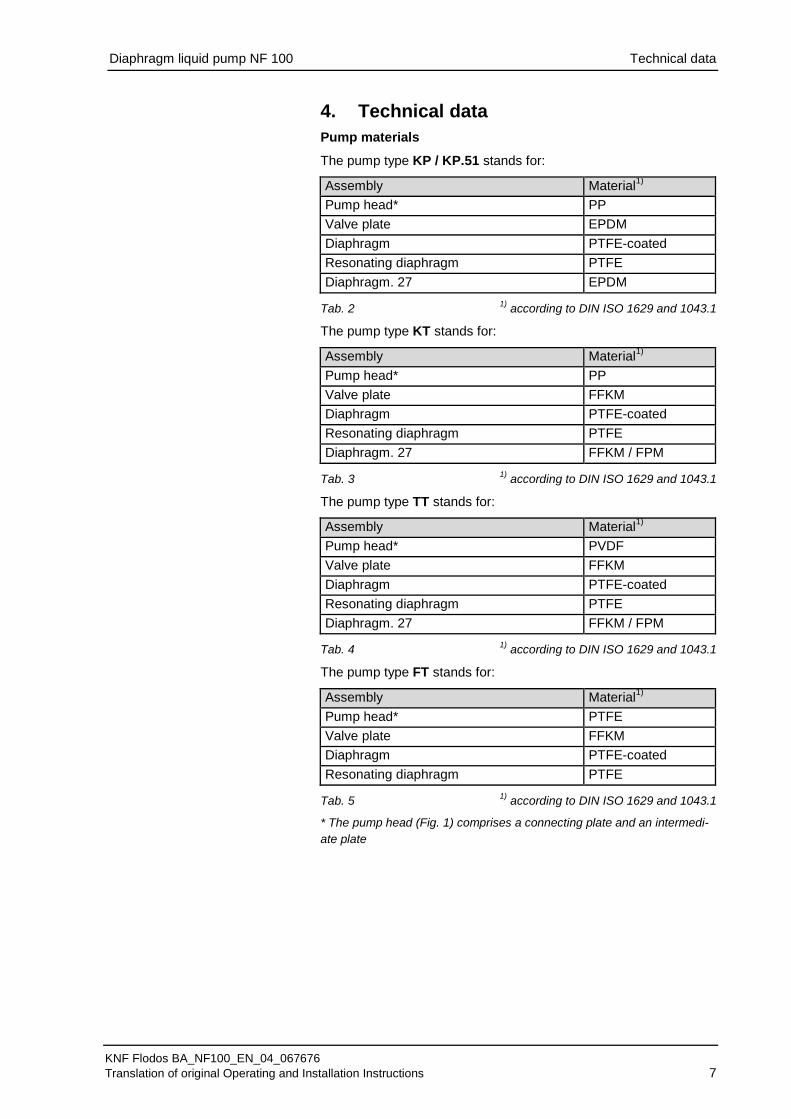
4. Technical data Pump materials
The pump type KP / KP.51 stands for:
Assembly Material1) Pump head* PP Valve plate EPDM Diaphragm PTFE-coated Resonating diaphragm PTFE Diaphragm. 27 EPDM
Tab. 2 1) according to DIN ISO 1629 and 1043.1
The pump type KT stands for:
Assembly Material1) Pump head* PP Valve plate FFKM Diaphragm PTFE-coated Resonating diaphragm PTFE Diaphragm. 27 FFKM / FPM
Tab. 3 1) according to DIN ISO 1629 and 1043.1
The pump type TT stands for:
Assembly Material1) Pump head* PVDF Valve plate FFKM Diaphragm PTFE-coated Resonating diaphragm PTFE Diaphragm. 27 FFKM / FPM
Tab. 4 1) according to DIN ISO 1629 and 1043.1
The pump type FT stands for:
Assembly Material1) Pump head* PTFE Valve plate FFKM Diaphragm PTFE-coated Resonating diaphragm PTFE
Tab. 5 1) according to DIN ISO 1629 and 1043.1
* The pump head (Fig. 1) comprises a connecting plate and an intermedi-ate plate

Diaphragm liquid pump NF 100 Technical data
KNF Flodos BA_NF100_EN_04_067676 Translation of original Operating and Installation Instructions 8
Hydraulic ratings
Parameter Value Flow rate NF 100 [l/min] 1), 2) ≥ 1.2 Flow rate NF 1.100 [l/min] 1), 2) ≥ 1.3 Flow rate NFB 100 [l/min] 1), 2) ≥ 2 x 1.3 Max. permissible pressure NF 100, NFB 100 [bar g]
1
Max. permissible pressure NF 1.100 [bar g]
6
Suction head [mWG] 3 Tab. 6
1) Measured with water at 20 °C / at atmospheric pressure
2) Flow rates may vary from the values shown, depending on fluid viscosi-ty, pump head material and the hoses / hose connectors used. Hydraulic connections
Parameter Value NF 100 / NF 1.100 / NFB 100 G 1/8" UNF 100 / UNF 1.100 / UNFB 100 NPT 1/8" Recommended hose size ID [mm] 8
Tab. 7
Specifications NF 100 E
Motor voltage 230V / 50Hz Power consumption [W] 43 Max. I load [A] 0.37 Max. permissible current consumption [A] 0.43
Protection class [-] IP 00 Weight1) [g] 1100
Tab. 8
Specifications NF 100 AA
Motor voltage 230V / 50Hz Power consumption [W] 86 Max. I load [A] 0.36 Max. permissible current consumption [A] 0.50
Protection class [-] IP 54 Weight1) [g] 2430
Tab. 9
Diaphragm liquid pump NF 100 Technical data
KNF Flodos BA_NF100_EN_04_067676 Translation of original Operating and Installation Instructions 9
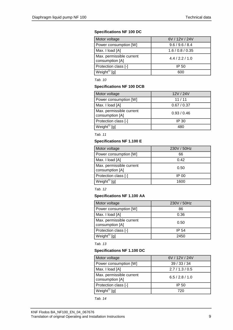
Specifications NF 100 DC
Motor voltage 6V / 12V / 24V Power consumption [W] 9.6 / 9.6 / 8.4 Max. I load [A] 1.6 / 0.8 / 0.35 Max. permissible current consumption [A] 4.4 / 2.2 / 1.0
Protection class [-] IP 50 Weight1) [g] 600
Tab. 10
Specifications NF 100 DCB
Motor voltage 12V / 24V Power consumption [W] 11 / 11 Max. I load [A] 0.67 / 0.37 Max. permissible current consumption [A] 0.93 / 0.46
Protection class [-] IP 30 Weight1) [g] 480
Tab. 11
Specifications NF 1.100 E
Motor voltage 230V / 50Hz Power consumption [W] 66 Max. I load [A] 0.42 Max. permissible current consumption [A] 0.50
Protection class [-] IP 00 Weight1) [g] 1600
Tab. 12
Specifications NF 1.100 AA
Motor voltage 230V / 50Hz Power consumption [W] 86 Max. I load [A] 0.36 Max. permissible current consumption [A] 0.50
Protection class [-] IP 54 Weight1) [g] 2450
Tab. 13
Specifications NF 1.100 DC
Motor voltage 6V / 12V / 24V Power consumption [W] 39 / 33 / 34 Max. I load [A] 2.7 / 1.3 / 0.5 Max. permissible current consumption [A] 6.5 / 2.8 / 1.0
Protection class [-] IP 50 Weight1) [g] 720
Tab. 14

Diaphragm liquid pump NF 100 Technical data
KNF Flodos BA_NF100_EN_04_067676 Translation of original Operating and Installation Instructions 10
Specifications NF 1.100 DCB
Motor voltage 12V / 24V Power consumption [W] 18 / 18 Max. I load [A] 1.29 / 0.75 Max. permissible current consumption [A] 1.5 / 0.75
Protection class [-] IP 30 Weight1) [g] 500
Tab. 15 Specifications NFB 100 DCB-4
Motor voltage 12V / 24V Power consumption [W] 15 / 15 Max. I load [A] 1.25 / 0.63 Max. permissible current consumption [A] 1.5 / 0.75
Protection class [-] IP 30 Weight1) [g] 640
Tab. 16
1) The weight may differ slightly from the stated value, depending on the version.
Electrostatic sensitive components (ESD)
Other parameters
Parameter Value Permissible ambient temperature range (°C)
+ 5 to + 40
Permissible media temperature range (°C)
+ 5 to + 80
Permissible kinematic viscosity of medium [cSt]
≤ 150
Tab. 17

Diaphragm liquid pump NF 100 Assembly and function
KNF Flodos BA_NF100_EN_04_067676 Translation of original Operating and Installation Instructions 11
5. Assembly and function 1 Outlet 2 Inlet 3 Connecting plate 4 Motor 5 Leads 6 Head plate 7 Intermediate plate
Fig. 1: Diaphragm liquid pump NF 100
1 Outlet valve 2 Inlet valve 3 Working chamber 4 Diaphragm 5 Eccentric 6 Connecting rod 7 Pump drive
Fig. 2: Operating principle
The diaphragm liquid pumps are based on reciprocating displace-ment pump technology. The elastic diaphragm (4) is moved up and down by the eccentric (5) and the connecting rod (6). In the down-ward stroke it aspirates the medium to be transferred via the inlet valve (2). In the upward stroke, the diaphragm pushes the medium out of the pump head via the outlet valve (1). The diaphragm hermetically seals off the working chamber (3) from the pump drive (7). NF 100 version (fixed flow rate)
This pump type represents this product in its simplest form and transfers media at the fixed flow rate. NF 100.27 version (fixed flow rate with overpressure limiting)
If the diaphragm liquid pump is operating against a closed system, the delivery pressure quickly exceeds the maximum permissible value. To prevent this from happening, an overflow valve is inte-grated in the top part of the pump head. If the pressure exceeds the adjustable limit range (min. 1.5 to max. 6.5 barg), the valve opens and the liquid circulates from the pressure side to the suc-tion side via an internal bypass system. This prevents any further pressure rise. NFB 100 version (double-headed pump with fixed flow rate)
This pump type has two NF100 pump heads that can be operated individually or together (see Chapter 6.3.2).

Diaphragm liquid pump NF 100 Installation and connection
KNF Flodos BA_NF100_EN_04_067676 Translation of original Operating and Installation Instructions 12
6. Installation and connection Only install the pumps under the operating parameters and condi-tions described in Chapter 4, Technical data.
Observe the safety precautions (see Chapter 3).
6.1. Installation Before installation, store the pump at the installation location to
bring it up to ambient temperature.
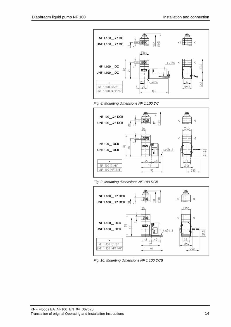
Mounting dimensions (see Fig. 3 to 11)
Fig. 3: Mounting dimensions NF 100 E
Fig. 4: Mounting dimensions NF 1.100 E
Mounting dimensions

Diaphragm liquid pump NF 100 Installation and connection
KNF Flodos BA_NF100_EN_04_067676 Translation of original Operating and Installation Instructions 13
Fig. 5: Mounting dimensions NF 100 AA
Fig. 6: Mounting dimensions NF 1.100 AA
Fig. 7: Mounting dimensions NF 100 DC
Diaphragm liquid pump NF 100 Installation and connection
KNF Flodos BA_NF100_EN_04_067676 Translation of original Operating and Installation Instructions 14
Fig. 8: Mounting dimensions NF 1.100 DC
Fig. 9: Mounting dimensions NF 100 DCB
Fig. 10: Mounting dimensions NF 1.100 DCB
Diaphragm liquid pump NF 100 Installation and connection
KNF Flodos BA_NF100_EN_04_067676 Translation of original Operating and Installation Instructions 15
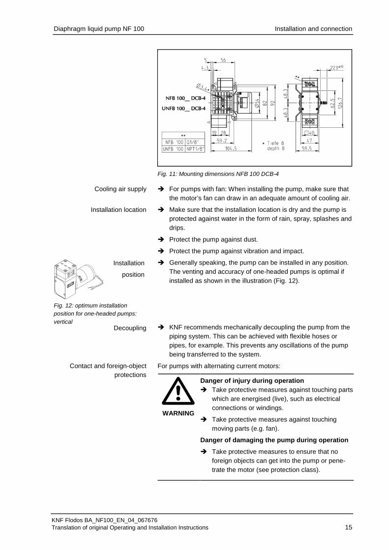
Fig. 11: Mounting dimensions NFB 100 DCB-4 For pumps with fan: When installing the pump, make sure that
the motor’s fan can draw in an adequate amount of cooling air.
Make sure that the installation location is dry and the pump is protected against water in the form of rain, spray, splashes and drips.
Protect the pump against dust.
Protect the pump against vibration and impact.
Generally speaking, the pump can be installed in any position. The venting and accuracy of one-headed pumps is optimal if installed as shown in the illustration (Fig. 12).
KNF recommends mechanically decoupling the pump from the piping system. This can be achieved with flexible hoses or pipes, for example. This prevents any oscillations of the pump being transferred to the system.
For pumps with alternating current motors:
WARNING
Danger of injury during operation Take protective measures against touching parts
which are energised (live), such as electrical connections or windings.
Take protective measures against touching moving parts (e.g. fan).
Danger of damaging the pump during operation
Take protective measures to ensure that no foreign objects can get into the pump or pene-trate the motor (see protection class).
Cooling air supply
Installation location
Installation
position
Fig. 12: optimum installation position for one-headed pumps: vertical
Decoupling
Contact and foreign-object protections
Diaphragm liquid pump NF 100 Installation and connection
KNF Flodos BA_NF100_EN_04_067676 Translation of original Operating and Installation Instructions 16
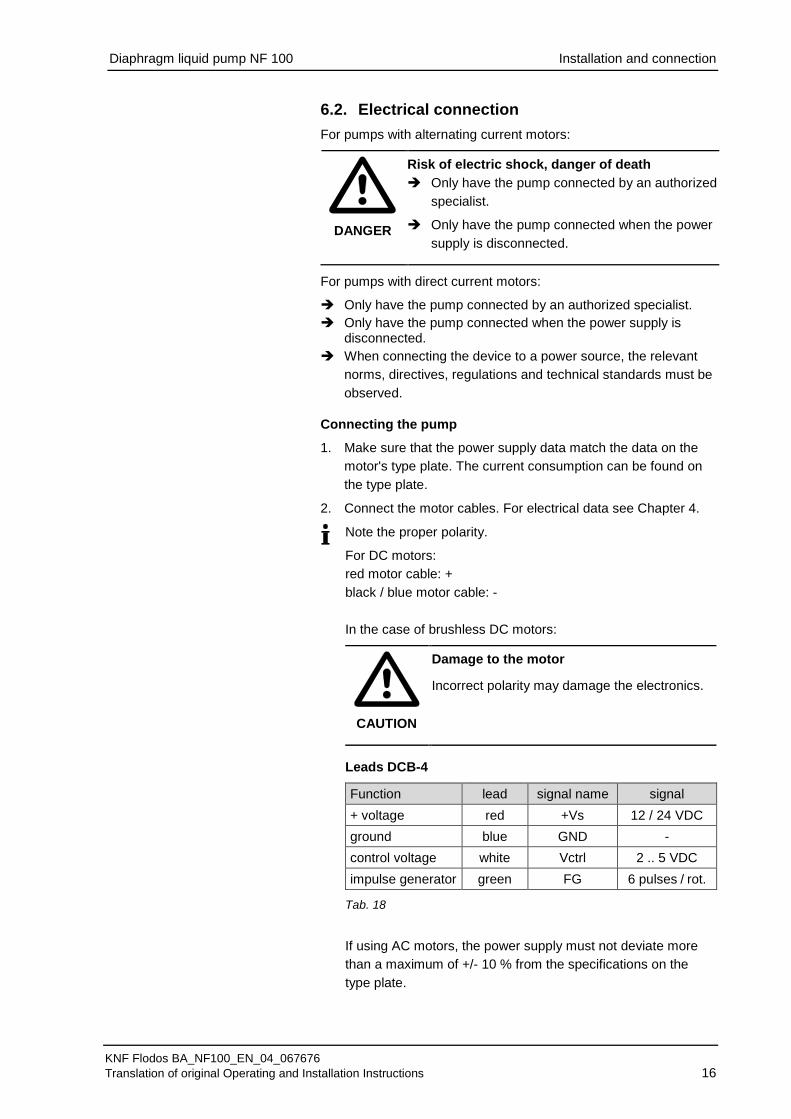
6.2. Electrical connection For pumps with alternating current motors:
DANGER
Risk of electric shock, danger of death Only have the pump connected by an authorized
specialist.
Only have the pump connected when the power supply is disconnected.
For pumps with direct current motors:
Only have the pump connected by an authorized specialist. Only have the pump connected when the power supply is
disconnected. When connecting the device to a power source, the relevant
norms, directives, regulations and technical standards must be observed.
Connecting the pump
Make sure that the power supply data match the data on the 1. motor's type plate. The current consumption can be found on the type plate.
Connect the motor cables. For electrical data see Chapter 4. 2.
Note the proper polarity.
For DC motors: red motor cable: + black / blue motor cable: - In the case of brushless DC motors:
CAUTION
Damage to the motor Incorrect polarity may damage the electronics.
Leads DCB-4
Function lead signal name signal + voltage red +Vs 12 / 24 VDC ground blue GND - control voltage white Vctrl 2 .. 5 VDC impulse generator green FG 6 pulses / rot.
Tab. 18
If using AC motors, the power supply must not deviate more than a maximum of +/- 10 % from the specifications on the type plate.

Diaphragm liquid pump NF 100 Installation and connection
KNF Flodos BA_NF100_EN_04_067676 Translation of original Operating and Installation Instructions 17
In order to ensure that emissions comply with the EN 55011 or EN 55022 emission standards, this pump type with a brushless DC motor DCB must be fitted with a supplemental circuit. The supple-mental circuit must be installed as close as possible to the motor.
The supplemental circuit must be installed according to the follow-ing wiring diagram and its defined components in order to achieve the required level of attenuation.
Optimum circuit Adequate circuit Fig. 13: Supplemental circuit
Supplemental circuit for brushless DCB motors
C1: Condenser 1 µF / UN > 30 V
C2: Condenser 1000 µF / UN > 30 V
L1: Choke coil 6 µH / IN > 1.5 A
Diaphragm liquid pump NF 100 Installation and connection
KNF Flodos BA_NF100_EN_04_067676 Translation of original Operating and Installation Instructions 18
6.3. Hydraulic connection Only connect components to the pump that are designed to
handle the hydraulic data of the pump (see Chapter 4, Technical data).
Only use hoses that are suitable for the maximum permissible operating pressure of the pump (see Chapter 4).
Only use hoses that are sufficiently chemically resistant to the liquids being transferred.
6.3.1. Connecting the pump
Arrows on the pump head indicate the flow direction.
Remove the protective caps. 1.
Connect the suction and pressure lines. 2.
Keep the suction line as short as possible in order to keep the priming process as brief as possible.
If the pump is used to build up pressure, make sure that all 3. transition joints between hose and pump are secure in order to ensure that the hoses cannot come off.
Check that the hoses and transition joints are fitted correctly 4. and securely.
Check that the system is leak-tight. 5.
Connected components
Hoses

Diaphragm liquid pump NF 100 Installation and connection
KNF Flodos BA_NF100_EN_04_067676 Translation of original Operating and Installation Instructions 19
6.3.2. NFB 100 hose configuration
A double-headed pump is normally selected to reduce the pressure surges caused by the alternation between suction and exhaust in a diaphragm pump. In order to achieve this effect, in addition to the pump configuration it is important to configure the hoses correctly.
For low pulsation (pressure surges) in NFB pumps:
Use pump in non-boxer (standard) version so that the heads expel alternately.
Configure pump head hoses in parallel (see Fig. 15).
Keep hoses between pump and junction as short as possible.
As little constriction as possible should be caused when using connecting components. As a guide: min. inner diameter 5.5 mm.
Contact your KNF technical advisor if you have any questions (see last page for telephone number).
Fig. 15: NFB 100 hose configuration for low pulsation
CAUTION
Changed technical characteristics In the case of NFB versions, the use of .27 versions may affect technical characteristics. (See Fig. 14, Hose connection options b) and d) ).
Fig. 14: Hose connection options
for NFB versions
Fig. 16: no series connection in the
case of NFB versions
CAUTION
Series connection damages pump If the two heads in the NFB versions are connected in series, the pump will be damaged, and may leak.

Diaphragm liquid pump NF 100 Operation
KNF Flodos BA_NF100_EN_04_067676 Translation of original Operating and Installation Instructions 20
7. Operation Operate the pumps only under the operating parameters and
conditions described in Chapter 4, Technical data.
Make sure that the pumps are being used properly (see Chap-ter 2.1).
Avoid improper use of the pumps (see Chapter 2.2).
Observe the safety precautions (see Chapter 3).
The pumps are components that are intended to be incorpo-rated into another machine. Before putting them into service it must be established that the machinery or systems in which they are installed meet the relevant regulations.
CAUTION
Risk of burning The drive heats up. Avoid contact with the pump drive.
Avoid contact with flammable materials.
Excessive pressure and the inherent dangers thereof can be prevented by placing a bypass line with a pressure relief valve between the pressure and suction side of the pump. For further information, contact your KNF technical adviser (for telephone number, see last page).
CAUTION
Risk of burns when transferring hot media Do not touch the pump or the media transfer
system.
Avoid contact with flammable materials.
If the pump stops running, restore the system to normal at-
mospheric pressure.
For pumps with thermal switch or electronic overload protection:
WARNING
Risk of physical injury and damage to the pump due to automatic start If the pump overheats and pump operation is stopped by the thermal switch / electronics, the pumps will restart automatically as soon as they have had time to cool down. Take steps to ensure that this cannot produce a
hazardous situation.
Pump standstill
Diaphragm liquid pump NF 100 Operation
KNF Flodos BA_NF100_EN_04_067676 Translation of original Operating and Installation Instructions 21
Switching the pumps on and off
The motor speed of the pump, and thus the flow rate, is adjustable and can also be regulated to some extent.
For more details, see Chapter 4, Technical data Duty cycle / short cycle operation
KNF pumps are designed for continuous operation.
Short start and stop cycles may adversely affect the service life of the brushed motors.
If the pump is operated with short cycles in your application, please contact a KNF technical adviser for further information (for telephone number, see last page).
Switching on the pump
In order to ensure that the pump starts every time, make sure that counterpressure is reduced to an acceptable level before start-up. This should also be done during operation after a brief power cut.
For more specific information contact your KNF technical adviser.
Switching off the pump
KNF recommends: If transferring aggressive liquids, the pump should be flushed thoroughly prior to switch off (see Chapter 8.2.1), as this will help to lengthen the service life of the dia-phragm.
Restore the system to normal atmospheric pressure (release hydraulic pressure in pump).
Setting and regulating motor speed
Short cycle operation
CAUTION
Overpressure on the suction side causes medi-um to flow through the switched-off pump Take steps to ensure that this cannot produce a
hazardous situation.
Diaphragm liquid pump NF 100 Operation
KNF Flodos BA_NF100_EN_04_067676 Translation of original Operating and Installation Instructions 22
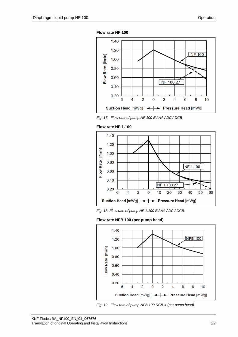
Flow rate NF 100
Fig. 17: Flow rate of pump NF 100 E / AA / DC / DCB Flow rate NF 1.100
Fig. 18: Flow rate of pump NF 1.100 E / AA / DC / DCB Flow rate NFB 100 (per pump head)
Fig. 19: Flow rate of pump NFB 100 DCB-4 (per pump head)

Diaphragm liquid pump NF 100 Servicing
KNF Flodos BA_NF100_EN_04_067676 Translation of original Operating and Installation Instructions 23
8. Servicing 8.1. Servicing schedule Component Servicing interval Pump - Regular inspection for external
damage or leaks Pump head - Clean if the flow rate decreases, the
pump does not work or no vacuum is created (Chapter 8.2)
Diaphragm, valve plates and seals
- Change as soon as pumping capac-ity decreases, preferably sooner
Tab. 19
8.2. Cleaning
WARNING
Health hazard due to dangerous substances in the pump Depending on the medium transferred, caustic burns or poisoning are possible. Wear protective clothing if necessary, e.g. pro-
tective gloves.
Flush the pump with a neutral liquid and pump empty.
8.2.1. Flushing the pump
When transferring aggressive media, KNF recommends flush-ing the pump with air (or an inert gas if necessary for safety reasons) under atmospheric conditions for a few minutes be-fore switching off in order to extend the service life of the dia-phragm.
8.2.2. Preparations for disassembly
Flush the pump with a suitable neutralising liquid, and make 1. sure that no dangerous substances are left in the pump
Pump empty 2.
Separate electrical connections 3.
Disconnect hoses from pump head 4.
Qty Tools for KP, KP.51, KT and TT versions 1 Torx 20 screwdriver Qty Tools for FT version 1 Phillips screwdriver No. 2
Tab. 20
Information on procedure
Tools

Diaphragm liquid pump NF 100 Servicing
KNF Flodos BA_NF100_EN_04_067676 Translation of original Operating and Installation Instructions 24
8.2.3. Disassembling the pump head
Loosen the four head screws (1) and remove the whole head. 1.
Take the valve plate (6) out of the intermediate plate (7). 2.
Remove the resonating diaphragm (3), or resonating dia-3. phragm.27 (15), if fitted diaphragm.27 (14) and pressure spring.27 (13) from the connecting plate (5).
Remove O-ring (4) from head plate (2) or (12). 4.
Carefully grip the diaphragm (8) and remove by turning anti-5. clockwise. Remove the washers (9) and make sure that no washers 9 fall into the pump housing.
We recommend replacing the diaphragm (8). 8.2.4. Clean or replace parts
Clean the diaphragm (8), O-Ring (4), resonating diaphragm 6. (3), or resonating diaphragm.27 (15), if fitted diaphragm.27 (14), valve plate(6), intermediate plate (7) and connecting plate (5) with a cloth and then blow off with compressed air or re-place.
8.2.5. Assembling the pump head
Place the same number of washers on the connecting rod (9) 1. as were there previously. Make sure that no washers (9) fall in-to the pump housing.
Screw in the diaphragm (8). By lightly pressing on the dia-2. phragm push the ridge on the underside of the diaphragm into the groove of the housing.
Place the "dust free“ valve plate(6) into the intermediate plate 3. (7), making sure it is in the correct position.
The method of assembly which follows will differ according to the pump type used. For this reason, please proceed with the section (NF 100 and NFB 100 versions or NF 100.27 ver-sion) that corresponds to the pump type you are using.
NF 100 and NF 100 versions
Insert the resonating diaphragm (3) in the connecting plate (5) 4. and cover with the head plate (2) fitted with a new O-ring (4).
The positions of the intermediate plate (7), the connecting plate 5. (5) and the head plate (2) with respect to one another are de-termined by the arrangement of the visible grooves.
Insert the four head screws (1) in the through holes of the 6. pump head.
Make sure that the flow direction of the pump head (see direc-7. tional arrow on the head plate (2)) is the same as previously.
Place the pump head onto the pump housing and alternately 8. tighten the four head screws (1). The maximum tightening torque is 2.5 Nm.
Reconnect the hoses to the pump head. 9.
Fig. 20: NF 100
Fig. 21:
NF 100 .27
1 Head screw 2 Head plate 3 Resonating diaphragm 4 O-Ring 5 Connecting plate 6 Valve plate 7 Intermediate plate 8 Diaphragm 9 Washer 10 Setscrew 11 Hexagon nut 12 Head plate.27 13 Pressure spring.27 14 Diaphragm.27 15 Resonating diaphragm.27

Diaphragm liquid pump NF 100 Servicing
KNF Flodos BA_NF100_EN_04_067676 Translation of original Operating and Installation Instructions 25
NF 100.27 version
Insert resonating diaphragm.27 (15) in the connecting plate (5). 4.
Place the diaphragm.27 (14) centrally on the resonating dia-5. phragm.27 (15).
Place the compression spring.27 (13) over the thread of the 6. diaphragm.27 (14).
Carefully place head plate.27 (12) with fitted new O-ring (4), 7. screwed-in setscrew (10) and hexagon nut (11) over the whole unit.
The positions of the intermediate plate (7), the connecting plate 8. (5) and head plate.27(12) with respect to one another are de-termined by the arrangement of the visible grooves.
Insert the four head screws (1) in the through holes of the 9. pump head.
Make sure that the flow direction of the pump head (see direc-10. tional arrow on head plate.27 (12)) is the same as previously.
Place the pump head onto the pump housing and alternately 11. tighten the four head screws (1). The maximum tightening torque is 2.5 Nm.
Reconnect the hoses to the pump head. 12. The activities described above should not alter the set pres-
sure of the overflow valve. If it is found that the setting has changed after assembly, the value can be readjusted within the permissible range of the pump in accordance with the instruc-tions in Chapter 8.3, if necessary readjusting the peripheral in-stallations.
CAUTION
Escaping liquid After assembly the pump may not be leak-tight due to incorrect assembly, damaged or soiled seal faces, or other reasons. Run pump for several minutes with a harmless
liquid at maximum operating pressure.
Check that pump is leak-tight
Diaphragm liquid pump NF 100 Servicing
KNF Flodos BA_NF100_EN_04_067676 Translation of original Operating and Installation Instructions 26
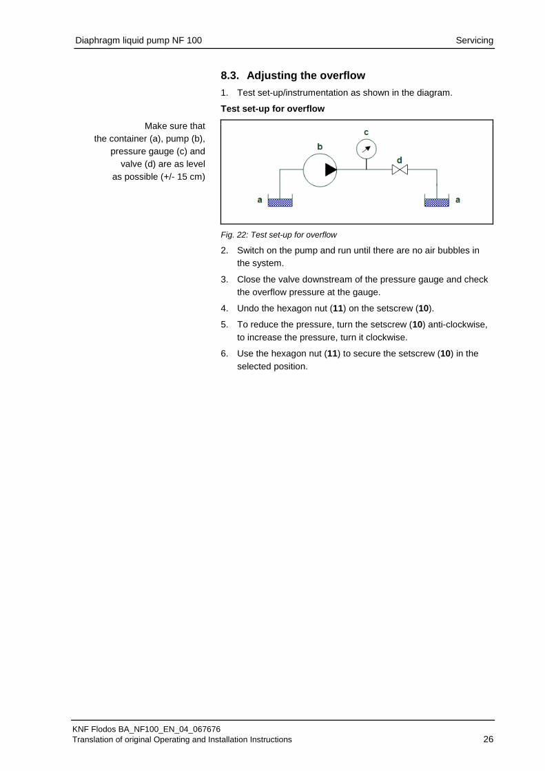
8.3. Adjusting the overflow Test set-up/instrumentation as shown in the diagram. 1.
Test set-up for overflow
Fig. 22: Test set-up for overflow
Switch on the pump and run until there are no air bubbles in 2. the system.
Close the valve downstream of the pressure gauge and check 3. the overflow pressure at the gauge.
Undo the hexagon nut (11) on the setscrew (10). 4.
To reduce the pressure, turn the setscrew (10) anti-clockwise, 5. to increase the pressure, turn it clockwise.
Use the hexagon nut (11) to secure the setscrew (10) in the 6. selected position.
Make sure that the container (a), pump (b),
pressure gauge (c) and valve (d) are as level
as possible (+/- 15 cm)

Diaphragm liquid pump NF 100 Troubleshooting
KNF Flodos BA_NF100_EN_04_067676 Translation of original Operating and Installation Instructions 27
9. Troubleshooting For pumps with alternating current motors:
DANGER
Risk of electric shock, danger of death Disconnect the pump from the power supply
before working on the pump.
Make sure that the pump is de-energised.
Pump does not work
Possible cause Remedy Pump not connected to power supply.
Connect pump to power supply.
Power supply is not switched on.
Switch on power supply.
Thermal switch or pump elec-tronics have tripped.
Disconnect pump from the mains. Allow pump to cool. Identify and eliminate cause of overheating/overload.
Connections or hoses are blocked.
Check connections and hoses. Remove blockage.
External valve is closed or filter is clogged.
Check external valves and filters.
Diaphragm or valve plate or seals are worn.
Replace diaphragm, valve plate and seals (see Chapter 8.2).
Tab. 21
Pump is not priming
Possible cause Remedy Suction side of pump not con-nected.
Connect the suction side of the pump.
Liquid in the container is too low.
Fill container.
Hose connections are not leak-tight.
Secure transition joints between hose and connections with clamps or clamping elements.
Peripheral valve is closed or filter is clogged.
Open the peripheral valve. Clean filter.
Pump head is filled with gas. The system is unable to handle the pressure on the pressure side.
Reduce pressure at pressure side.
Particles in the pump. Clean the pump head (see Chapter 8.2). The pump parts are not re-sistant to the medium to be transferred.
Replace the pump head with a compatible version.
Incorrect interchange of pres-sure and suction line connec-tions.
Remove pressure and suction lines and reconnect correctly.
Tab. 22

Diaphragm liquid pump NF 100 Troubleshooting
KNF Flodos BA_NF100_EN_04_067676 Translation of original Operating and Installation Instructions 28
Flow rate, suction head or pressure head is too low
The pump does not achieve the performance stated in the technical data or on the data sheet. Possible cause Remedy Components in the system connected to the suction and pressure sides, such as hoses, valves or filters, are causing too much resistance.
Modify installation, check the cross-section of components.
Hose connections are not leak-tight.
Secure transition joints between hose and hose connections with clamps or clamping elements
Particles in the pump. Clean the pump head, install suction-side filter if required (see Chapter 8.2).
Viscosity of the transferred medium is too high.
Contact KNF.
Incorrect interchange of pres-sure and suction line connec-tions.
Remove pressure and suction lines and reconnect correctly.
The pump parts are not re-sistant to the medium to be transferred.
Replace the pump head with a compatible version.
Tab. 23
Fault cannot be rectified
If you are unable to identify any of the above causes, please send the pump to KNF customer service (see address on last page).
Flush the pump to clear the pump head of any hazardous or 1. aggressive liquids (see Chapter 8.2.1).
Dismantle the pump. 2.
Clean the pump (see Chapters 8.2.2 to 8.2.5) 3.
Send the pump, with completed decontamination declaration 4. (see Chapter 11), to KNF customer service stating the nature of the transferred medium.

Diaphragm liquid pump NF 100 Spare parts and accessories
KNF Flodos BA_NF100_EN_04_067676 Translation of original Operating and Installation Instructions 29
10. Spare parts and accessories Spare parts kit
Spare parts kit Order No. Spare parts kit KP 1) 065261 Spare parts kit KT / TT 065262 Spare parts kit FT 152631 Spare parts kit KP.27 067529 Spare parts kit KT.27 / TT.27 067530
Tab. 24 1) For KP.51 version, contact your KNF technical advisor (see last page for telephone number). Accessories
Accessories Order No. Screw-in nipple with seal EPDM R1/8" 1) 156627 Screw-in nipple with seal EPDM NPT1/8" 156623 Screw-in nipple with seal FFKM R1/8" 1) 156626 Screw-in nipple with seal FFKM NPT1/8" 156622
Tab. 25 1) For connecting thread G1/8"
Diaphragm liquid pump NF 100 Decontamination declaration
KNF Flodos BA_NF100_EN_04_067676 Translation of original Operating and Installation Instructions 30
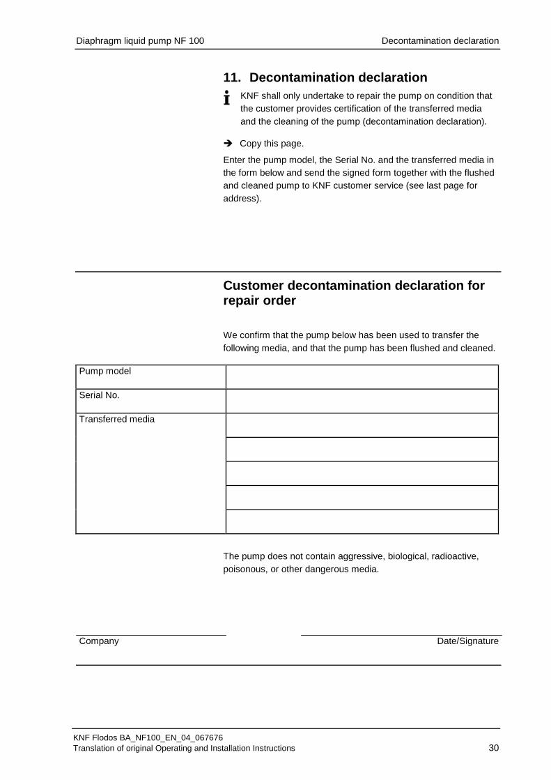
11. Decontamination declaration
KNF shall only undertake to repair the pump on condition that the customer provides certification of the transferred media and the cleaning of the pump (decontamination declaration).
Copy this page.
Enter the pump model, the Serial No. and the transferred media in the form below and send the signed form together with the flushed and cleaned pump to KNF customer service (see last page for address).
Customer decontamination declaration for repair order
We confirm that the pump below has been used to transfer the following media, and that the pump has been flushed and cleaned.
Pump model
Serial No.
Transferred media
The pump does not contain aggressive, biological, radioactive, poisonous, or other dangerous media.
Company Date/Signature

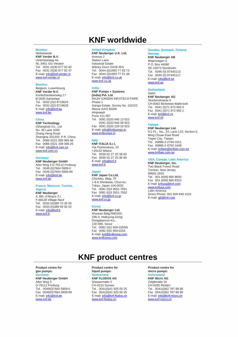
KNF worldwide
Benelux Netherlands KNF Verder B.V. Utrechtseweg 4a NL-3451 GG Vleuten Tel. 0031 (0)30 677 92 40 Fax 0031 (0)30 677 92 47 E-mail: [email protected] www.knf-verder.nl Benelux Belgium, Luxembourg KNF Verder N.V. Kontichsesteenweg 17 B-2630 Aartselaar Tel. 0032 (0)3 8719624 Fax 0032 (0)3 8719628 E-mail: [email protected] www.knf.be China KNF Technology (Shanghai) Co., Ltd No. 36 Lane 1000 Zhang Heng Road Shanghai 201203, P.R. China Tel. 0086 (0)21 685 965 66 Fax 0086 (0)21 339 006 26 E-mail: [email protected] www.knf.com.cn Germany KNF Neuberger GmbH Alter Weg 3 D-79112 Freiburg Tel. 0049 (0)7664 5909-0 Fax 0049 (0)7664 5909-99 E-mail: [email protected] www.knf.de France, Morocco, Tunisia, Algeria KNF Neuberger 4, Bld. d’Alsace Z.I. F-68128 Village-Neuf Tel. 0033 (0)389 70 35 00 Fax 0033 (0)389 69 92 52 E-mail: [email protected] www.knf.fr
United Kingdom KNF Neuberger U.K. Ltd. Avenue 2 Station Lane Industrial Estate Witney Oxon OX28 4FA Tel. 0044 (0)1993 77 83 73 Fax 0044 (0)1993 77 51 48 E-mail: [email protected] www.knf.co.uk India KNF Pumps + Systems (India) Pvt. Ltd. RAJIV GANDHI INFOTECH PARK Phase 1 Ganga Estate, Survey No. 152/2/2 Above AXIS BANK Hinjewadi Pune 411 057 Tel. 0091 (0)20 640 13 923 0091 (0)20 640 08 923 Fax 0091 (0)20 229 33 923 E-mail: [email protected] www.knfpumps.in Italy KNF ITALIA S.r.l. Via Flumendosa, 10 I-20132 Milano Tel. 0039 02 27 20 38 60 Fax 0039 02 27 20 38 48 E-mail: [email protected] www.knf.it Japan KNF Japan Co.Ltd. Chichibu, Bldg. 7F 1-8-6 Shinkawa, Chuo-ku, Tokyo, Japan 104-0033 Tel. 0081 (0)3 3551-7931 Fax 0081 (0)3 3551-7932 E-mail: [email protected] www.knf.co.jp Korea KNF Neuberger Ltd. Woosan Bldg.RM#202, 336-4, Hwikyung-Dong Dongdaemun-Ku., 130-090, Seoul Tel. 0082 (0)2 959-0255/6 Fax 0082 (0)2 959-0254 E-mail: [email protected] www.knfkorea.com
Sweden, Denmark, Finland, Norway KNF Neuberger AB Mejerivägen 4, P.O. Box 44060 SE-10073 Stockholm Tel. 0046 (0) 87445113 Fax 0046 (0) 87445117 E-mail: [email protected] www.knf.se Switzerland Sales KNF Neuberger AG Stockenstrasse 6 CH-8362 Bichelsee-Balterswil Tel. 0041 (0)71 973 993 0 Fax 0041 (0)71 973 993 1 E-mail: [email protected] www.knf.ch Taiwan KNF Neuberger Ltd. 9-2 FL., No., 24, Lane 123, Section 6, Ming Chuan East Road Taipei City, Taiwan Tel. 00886-2-2794-1011 Fax 00886-2-8792-1648 E-mail: [email protected] www.knftwn.com.tw USA, Canada, Latin America KNF Neuberger, Inc. Two Black Forest Road Trenton, New Jersey 08691-1810 Tel. 001 (609) 890 8600 Fax 001 (609) 890 8323 E-mail: [email protected] www.knfusa.com Latin America Direct Phone: 001 609 649 1010 E-mail: [email protected]
KNF product centres
Product centre for gas pumps: Germany KNF Neuberger GmbH Alter Weg 3 D-79112 Freiburg Tel. 0049(0)7664 5909-0 Fax 0049(0)7664 5909-99 E-mail: [email protected] www.knf.de
Product centre for liquid pumps: Switzerland KNF FLODOS AG Wassermatte 2 CH-6210 Sursee Tel. 0041(0)41 925 00 25 Fax 0041(0)41 925 00 35 E-mail: [email protected] www.knf-flodos.ch
Product centre for micro pumps: Switzerland KNF Micro AG Zelglimatte 1b CH-6260 Reiden Tel. 0041(0)62 787 88 88 Fax 0041(0)62 787 88 99 E-mail: [email protected] www.knf-micro.ch