diamond e-2000 fiber optic components · diamond fiber optic components cable assemblies and...
TRANSCRIPT

DIAMONDFiber Optic Components
CABLE ASSEMBLIES AND ADAPTERS
E-2000™ Family
SINGLE MODE PC/APCMULTIMODE PCPS, PSf, PM-PS, PSi, PSm, PSc, PM,VIS/NIR
Specifications subject to changewithout noticeBDD 1951622 10_16
DIAMOND SA • Via dei Patrizi 5 • CH-6616 Losone - SwitzerlandTel. +41 91 785 45 45 • Fax +41 91 785 45 00 • e-mail [email protected]
www.diamond-fo.comthe fiber meeting
Thanks to its different technologies, mechanical and optical interfaces, the E-2000™ fiber optic connector family can cover the most standard and cus-tomized requirements in response to the increasingly customer demands.The family includes: simplex, compact and backplane connectors and adapters, as well as a series of network accessories such as: attenuators, hybrid adapters, transition adapters, terminators, reflectors and receptacles.
FEATURES AND BENEFITS INCLUDE
Color-coding and mechanical keying to ensure correct matings.Spring-loaded protective cap for high power applications providing increased safety protectionSpecially designed body to prevent endface damage during matingModular designed mating adapters with metal protective shutters for high power applicationsEtO sterilizable components with optional O-ring seals IP65-rated (for E-2000™ Simplex and Compact) for safety, reliability, and quality in biomedical markets and applications subject to special environmental conditions.E-2000™ Simplex with non-magnetic components availableAssemblies available with different plastic and metal flexible jacketing: Elastometer (Hytrel), PEEK (Victrex 450), PA (Nylon), PTFE (Teflon), Stain- less steel.
Diamond composite ferrule (zirconia ceramic sleeve and titanium insert):
- Allows plastic deformation for our Active Core Alignment (A.C.A) - Unique 0.1 dB Insertion Loss - Custom drill sizes from 80μm to 800μm - Superior Ultra polishing - Custom ferrules for multi-fiber technology - Ultra-low ferrule O.D. tolerances
AVAILABLE TECHNOLOGIES AND OPTICAL INTERFACES
PS optical interfaces: PS collimated, PSf free space, PM-PS, PSi Free Standing, PSm Multimode, PSc collimator. Polarization Maintaining (PM) VIS/NIR for low wavelengths and small core fibers Optical Line Identification OLID assemblies E-2000™ FUSION for easy field termination of MM and SM fibers E-2000™ Crimp & Cleave for field termination of 200/230 μm HCS-fiber
E-2000™ Simplex
E-2000™ Accessories and active modules
E-2000™ Interlock and Power Solution (PS)
E-2000™ Backplane 2-6 channels
E-2000™ Compact

E-2000™ Family
ENVIRONMENTAL CONDITIONS
MEASUREMENT / TEST PARAMETERS METHOD
Change of temperature (Reliability) -40°C / +85°C / 1 h dwell / 500 cycles IEC 61300-2-22
Low temperature -51°C / 96 h MIL-STD-810F
Dry heat (Reliability) +85°C / 2'000 h IEC 61300-2-18
Termal shock -51°C / +71°C / 1 h dwell / 3 cycles MIL-STD-810F
Low pressure, procedure II 4’572 m / 1 h MIL-STD-810F
Low pressure, procedure III 2'438 m to 12’192 m / 60 s MIL-STD-810F
Damp heat, cyclic(Reliability) +25°C / +55°C / 95% r.h. / 100 cycles IEC 61300-2-46
Compositetemperature-humidity cycling
-10°C / +25°C / +65°C / 93% r.h. /15 cycles IEC 61300-2-21
Extended humidity (Reliability) +85°C / 85% rh / 2’000 h Telcordia GR-326-CORE
Salt mist +35°C / 50 g/l / 96 h IEC 61300-2-26
Tensile strength of couplingmechanism 40 N / 2 min IEC 61300-2-6
Cable retention 100 N / 2 min IEC 61300-2-4
Proof at 0° 4.5 Kg - 6.8 Kg / 5 sTelcordia
GR-326-CORE
Proof at 90° 2.3 Kg - 3.4 Kg / 5 s TelcordiaGR-326-CORE
Static side load 1 N / 1 h on cable version0.2 N / 5 min on fibre version IEC 61300-2-42
Cable torsion 15 N / ±180° / 25 cycles IEC 61300-2-5
Twist 1.35 Kg / ±1'800° / 10 cycles TelcordiaGR-326-CORE
Vibration, sinusoidal 10 Hz - 55 Hz / 1.5 mm / 30 min IEC 61300-2-1
Impact (freefall) 1.5 m / 5 drops IEC 61300-2-12
Bending moment 10 N / 2 min IEC 61300-2-7
Mating durability (Couplings) 500 cycles IEC 61300-2-2
Flexing of strain relief 2 N / +/-90° / 100 cycles IEC 61300-2-44
MECHANICAL CONDITIONS
THE E-2000™ SIMPLEX
Constant innovation in the field of fiber optics has created demand for products with ever increasing performance requirements. Diamond has responded to this challenge and expanded the E-2000™ connector system to address these needs throughout all market segments.The E-2000™ Simplex offers unparalleled 0.1 dB maximum insertion loss random mating, exceptional repeat-ability, while maintaining the already well established, superior features of the E-2000™ connector family.
STANDARDS
EN 86 275-801 „Connector sets of assessed quality for optical fibers and cables - Type LSH universal“ EN 86 275-802 „Connector sets of assessed quality for optical fibers and cables - Type LSH-HRL universal“ TIA/EIA 604-16 Fiber Optic Intermateability standard - Type IEC 61 754-15 “Fiber optic connector interfaces – Part 15: Type LSH connector family”
AVAILABLE AS
Standard terminated connector, also for applications up to 6W (E-2000™ PS)➢ Connector set (to be terminated with Diamond special equipment)
Insertion Loss (IL)
Return Loss (RL)
Repeatability of IL
Service life
Storage temperature
typ. 0.15 max 0.4
typ. 40
typ. 0.2 max 0.4
min 50
typ. 0.2 max 0.4
min 70*
max 0.1
min 85*
dB
dB
dB
-
°C
IEC 61300-3-4; λ = 1300/1550nm
IEC 61300-3-6; λ = 1300/1550nm
IEC 61300-2-2; λ = 1300/1550nm
According to field experience
max ±0.1
1000 mate/demate cycles
-40/+90**
MULTIMODE0° PC
SINGLE MODE0° PC
SINGLE MODE8° APC
SINGLE MODE8° 0.1 dB TEST CONDITIONSUNITS
-
* Measured with high precision reflectometer** May be further limited by cable specifications
OPTICAL SPECIFICATIONS
Simplex adapter with fixed flange
For firmly fixation
Versatile simplex adapter
Multiple swappable mounting flanges Suitable for IP65 version EtO-sterilizable

E-2000™ Family
COLOR KEYING
The E-2000TM system permits the user to specify the color of the thumb-latch and the mating adapter frame so that different line types, uses, destinations and points of origin, etc. can be readily identified.The thumb-latch and frame are available in eight distinct colors:
1. Blue 5. Orange 2. Beige (White) 6. Yellow 3. Black 7. Green 4. Red 8. Violet
MECHANICAL KEYING
Additionally, it will become increasingly necessary to guard against improper connection in multiple-service patch facilities. The E-2000TM system permits the inclusion of a mechanical keying mechanism to ensure channel differentiation.The mechanical keying options are also color-coded as follows:
Key Nr. 1 Red Key Nr. 4 Orange Key Nr. 2 Brown Key Nr. 5 Violet Key Nr. 3 Yellow Key Nr. 6 Beige (White)
NOTE As standard, Diamond uses colored connector bodies, cable boots and mating adapter housings to identify the fiber type (SM or MM 50/62.5μm) and ferrule polish (PC or APC). Diamond`s standard connector/boot/adaptor colors are as follows: Beige/Black/Beige for MM PC 50μm, Beige/Beige/Beige for MM PC 62.5μm, Blue/Blue/Blue for SM PC, and Green/Green/Green for SM APC. Other colors are available upon request.
Injection molded outer housing Connector housing totally encloses ferrule to
optimally protect it from dust, contaminants and scratches
DIAMOND two component ferrule Active Core Alignment minimizes fiber
core offset and ensure optimal connector performance
Modular designed compact mating adapter with interchangeable mounting bracket Permits dense packing Offers several installation solutions
Cable diameter independentcrimping sleeve
Universal bend protectionboot
Integrated metal protective cap Automatically protects personnel from eye-damaging laser radiation Closes automatically upon extraction to protect ferrule from dust and scratches Suitable for high power applications
Spring-loaded metal protection shutters Engages automatically to protect personnel
from eye-damaging laser radiation Angled, anti-reflection surface ensures low
reflectance in unmated state, inducing light diffusion
Positive latching mechanism with interchan geable, color-coded and mechanically-keyed thumb-latch Offers superior retention under axial load Allows higher packing densities Distinct color-coded thumb latch allows easy optical line identification and ordering
Interchangeable color-coded and mechani-cal-keyed frames (8 different colors and 6 different mechanical combinations) Permits clear and unmistakable identifica-
tion of lines on crowded panels Guards against improper connections Adaptable to evolving needs
All cable types supported

E-2000™ Family
THE E-2000™ COMPACT
The E-2000™ COMPACT DUPLEX combines the familiarity of the RJ45 design and the optical performances of the E-2000™ simplex connector. It is based on components of the E-2000™ simplex version and is joined by a simpleclip-bridge and a widened thumb-latch.The E-2000™ COMPACT is the ideal solution for applications where an increasing number of cabling installations isrequired, typically to support multimedia environments including voice, data and image transmission.The color and mechanical keying have the same identification as those of the E-2000™ Simplex connector.
STANDARDS
IEC 61 754-15 “Fiber optic connector interfaces – Part 15: Type LSH connector family”.
AVAILABLE AS
Standard terminated connector Connector set (to be terminated with Diamond special equipment)
THE E-2000™ BACKPLANE
The E-2000™ Backplane combines the advantages of the E-2000™ SYSTEM and an optimal guiding mechanism forsecure backplane connection. When mated, the PCB connector is retained in the mating adapter eliminating allstress on the PC Board.It uses the common components of the E-2000™ Simplex version which are joined by a simple clip-bridge whichincludes a radial, angular and longitudinal compensation. Clip bridges are available for 2 and 6 connectors.The E-2000™ Backplane offers the same optical performances as the E-2000™ simplex connector.The adapters can be easily mounted into the distribution panel.
The E-2000™Backplane covers all needs in this field of applications and offers:
Same optical peformances as the E-2000™ Simplex version Active push pull retention Sufficiently long pre-mating tracks for repeatable mating and high stability Backplane modules designed for integration into metric backplane system as per IEC 1070-4-100 Injection moulded housing (UL 94 V0 flammability rating) Positive latching mechanism with step process to prevent the backplane and the PCB from stress Backplane adapter with spring loaded shutters and connectors with protective metal caps Existing components can be upgraded to the backplane version with the use of a clip bridge and an adapted latch Longitudinal mating compensation
AVAILABLE AS
Standard terminated connector Connector set (to be terminated with Diamond special equipment)
The E-2000™ BACKPLANE is fully integrable into the IEC 1070-4-100 metric systemfor backplane copper connectors: the 2 channel unit is 1 SU high, the 6 channel unitis 2 SU high. Furthermore, they are fully modular combinable; to upgrade theE-2000™ BACKPLANE to system of multiple channel design.

E-2000™ Family
THE E-2000™ INTERLOCKDIAMOND presents a novel, reliable, and high-quality E-2000™ fiber optic connector and mating adapter with an integrated electrical circuit breaker.This is very useful in many laser systems where it is preferred to block the emission by means of an external shutter rather than, for instance, to alter the internal laser's driving conditions.The E-2000™ Interlock is particularly suitable for high-power applications or any other situation where light must be rapidly interrupted due to safety and protection reasons.The E-2000™ interlock is available in several Power Solution (PS) optical interfaces (i.e: PS collimated, PSf free space, PM-PS, PSm, etc.) and supports all other standard E-2000™ features:
Standard and small core fibers Standard, PM and other specialty fibers High precision core placements thanks to the active core alignment (A.C.A.) Color & mechanical coding Automated metal protection cap
The E-2000™ mating adapter also offers metal shutters and thanks to interchangeable mounting brackets supports alarge variety of installation solutions, even on PCB.
AVAILABLE AS
Standard terminated connector
OPTICAL SPECIFICATIONS FOR THE PS VERSION
CONNECTOR TYPE WAVELENGHT (nm)
IL (db) Against Reference RL Against Reference
typ. max.connected unmated
PC 0° APC 4° APC 4°
E-2000™ PS 1625 - 1550 - 1310 0.2 0.4 45 75
501060 - 980 0.3 0.6 35* 60*
TEST CONDITIONS IEC 61300-3-4IEC 61300-3-6
OLCR method / *OCWR method
* Values obtained with Diamond qualified fibers

2.5
ø 0.7
42 8.9
12.7
15
1010
8.6
9.75
16
+0.5 0
+0.4
0
9.1
Max wall thickness 1.6mm
CUT OUT
7.8
15.2
56
3
0.95
0.15
0.95
DETAILS X
PCB thickness: 1,6mm(Other fixation types upon request)
10 10 2.5
4.8
10 10 6.2
5.2
2.4
5.7
max. R 0.75
CONSTRUCTION
Interchangeable parts as from E-2000™ system
Metal swinging springfor electric contact
Plastic protection for metalswinging
MOUNTING INSTRUCTION
42 8.9
12.7
15
9.75
16
+0.5 0
+0.4
0
9.1
Max wall thickness 1.6mm
CUT OUT
7.8
15.2
56
3
0.95
0.15
0.95
DETAILS X
PCB thickness: 1,6mm(Other fixation types upon request)
10 10 2.5
4.8
10 10 6.2
5.2
2.4
5.7
max. R 0.75
Interchangeable parts asfrom E-2000™ system
Metal swinging springfor electric contact
Plastic protection for metalswinging spring
8.6
ø 0.7
A
B
C
D
E
F
SAFETY INFORMATION
The Interlock feature in the E-2000™ connector has to be considered as being part of a complete safety system, as it cannot be deemed as a stand-alone safety device.In order to ensure safe operation it is mandatory to follow the operational information below:
Although equipped with connectors having an Interlock system, lasers should be operated only when connec- tors are mated The light source must be switched off during mating and de-mating.
WARNING: The user is responsible for ensuring that all local, state, and national laws, rules, codes, and regula-tions relating to the use of the E-2000™ Interlock in any particular application are satisfied.
E-2000™ Family
2.5
ø 0.7
42 8.9
12.7
15
1010
8.6
9.75
16
+0.5 0
+0.4
0
9.1
Max wall thickness 1.6mm
CUT OUT
7.8
15.2
56
3
0.95
0.15
0.95
DETAILS X
PCB thickness: 1,6mm(Other fixation types upon request)
10 10 2.5
4.8
10 10 6.2
5.2
2.4
5.7
max. R 0.75
42 8.912
.715
9.75
16
+0.5 0
+0.4
0
9.1
Max wall thickness 1.6mm
CUT OUT
7.8
15.2
56
3
0.95
0.15
0.95
DETAILS X
PCB thickness: 1,6mm(Other fixation types upon request)
10 10 2.5
4.8
10 10 6.2
5.2
2.4
5.7
max. R 0.75
Interchangeable parts asfrom E-2000™ system
Metal swinging springfor electric contact
Plastic protection for metalswinging spring
8.6
ø 0.7
A
B
C
D
E
F
42 8.9
12.7
15
9.75
16
+0.5 0
+0.4
0
9.1
Max wall thickness 1.6mm
CUT OUT
7.8
15.2
56
3
0.95
0.15
0.95
DETAILS X
PCB thickness: 1,6mm(Other fixation types upon request)
10 10 2.5
4.8
10 10 6.2
5.2
2.4
5.7
max. R 0.75
Interchangeable parts asfrom E-2000™ system
Metal swinging springfor electric contact
Plastic protection for metalswinging spring
8.6
ø 0.7
A
B
C
D
E
F
SAFETY INFORMATION FOR E-2000™ POWER SOLUTION
CLEANING
Cleanliness still remains the key word using high power. The basic concept using PS connectors is therefore thefollowing:“before each mating procedure, the connectors must be absolutely clean and inspected with a microscope“.The ferrule`s surface inspection should be performed using an optical microscope with a magnification of at least 200x. The connector is normally affected by contamination during handling and mating procedures; the degree of cleanliness of the overall installation is also a critical parameter to be taken into consideration.
HANDLING
The Power Solution connectors should be operated with high power only when connected. When unmated, the lightsource must absolutely be switched off.
SAFETY
Optical connectors are passive components not subjected to Laser safety, but when integrated in an active system,as the output side of a light source, they will be submitted to it.The following aspects are to be taken into account when evaluating the laser safety requirements:- The exit beam of these connectors have a lower NA as standard connectors in air (NA=0.035) or ca. 2° divergence.This is used in the calculation of the amount of light that can enter the pupil at 1m.
The following safety precautions are to be considered as a starting point, each is responsible to edict proper safety protocols andwe intend here just as to help doing this. The following precautions should not be considered as sufficient and should be reevaluatedfrom case to case.- usage in restricted area, access only for authorized and qualified personnel.- use protective glasses, skin protective measures recommended.- optical behavior under control: eliminate reflections (also diffuse), close unused optical channels, avoid light beams at eye level.- switch on/off system with remote control or interlock and additional automatic switch off safety system.- warning signal when sources are active.- laser classification markings and danger indications.
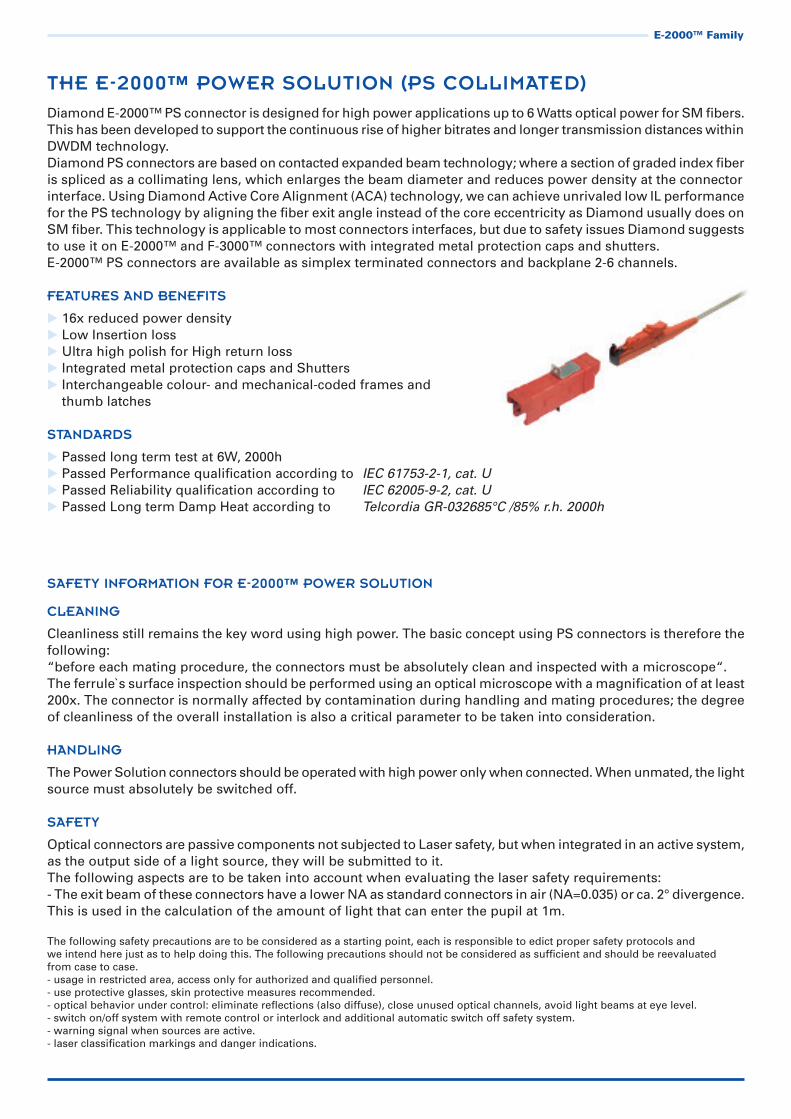
THE E-2000™ POWER SOLUTION (PS COLLIMATED)
Diamond E-2000™ PS connector is designed for high power applications up to 6 Watts optical power for SM fibers.This has been developed to support the continuous rise of higher bitrates and longer transmission distances withinDWDM technology.Diamond PS connectors are based on contacted expanded beam technology; where a section of graded index fiberis spliced as a collimating lens, which enlarges the beam diameter and reduces power density at the connectorinterface. Using Diamond Active Core Alignment (ACA) technology, we can achieve unrivaled low IL performancefor the PS technology by aligning the fiber exit angle instead of the core eccentricity as Diamond usually does on SM fiber. This technology is applicable to most connectors interfaces, but due to safety issues Diamond suggests to use it on E-2000™ and F-3000™ connectors with integrated metal protection caps and shutters.E-2000™ PS connectors are available as simplex terminated connectors and backplane 2-6 channels.
FEATURES AND BENEFITS
16x reduced power densityLow Insertion lossUltra high polish for High return lossIntegrated metal protection caps and ShuttersInterchangeable colour- and mechanical-coded frames and thumb latches
STANDARDS
Passed long term test at 6W, 2000h Passed Performance qualification according to IEC 61753-2-1, cat. U Passed Reliability qualification according to IEC 62005-9-2, cat. U Passed Long term Damp Heat according to Telcordia GR-032685°C /85% r.h. 2000h
E-2000™ Family
max. ±0.1
1000 mate/demate cycles
-25/+70**
-25/+70**
IEC 61300-3-4; λ = 1300/1550nm
IEC 61300-3-6; λ = 1300/1550nm
IEC 61300-2-2; λ = 1300/1550nm
According to field experiences
typ. 0.2 max 0.5
min. 40
typ. 0.25 max. 0.5
min. 50
typ 0.25 max. 0.5
min. 70*
dB
dB
dB
°C
°C
Insertion Loss (IL)
Return Loss (RL)
Repeatability of IL
Service life
Operating temperature
Storage temperature
TEST CONDITIONSMULTIMODE0° PC
SINGLE MODE0° PC
SINGLE MODE8° APC
UNITS
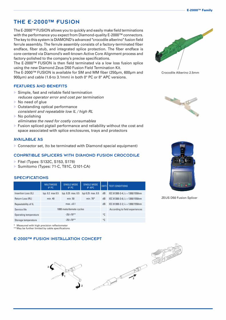
THE E-2000™ FUSION
The E-2000™ FUSION allows you to quickly and easily make field terminations with the performance you expect from Diamond-quality E-2000™ connectors.The key to this system is DIAMOND's advanced "crocodile alberino" fusion fieldferrule assembly. The ferrule assembly consists of a factory-terminated fiberendface, fiber stub, and integrated splice protection. The fiber endface is core-centered via Diamond’s well-known Active Core Alignment process and factory-polished to the company’s precise specifications.The E-2000™ FUSION is then field terminated via a low loss fusion splice using the new Diamond Zeus D50 Fusion Field Termination Kit.The E-2000™ FUSION is available for SM and MM fiber (250μm, 600μm and 900μm) and cable (1.6-to 3.1mm) in both 0° PC or 8° APC versions.
FEATURES AND BENEFITS
Simple, fast and reliable field termination reduces operator error and cost per termination No need of glue Outstanding optical performance consistent and repeatable low IL / high RL No polishing eliminates the need for costly consumables Fusion spliced pigtail performance and reliability without the cost and space associated with splice enclosures, trays and protectors
AVAILABLE AS
Connector set, (to be terminated with Diamond special equipment)
COMPATIBLE SPLICERS WITH DIAMOND FUSION CROCODILE
Fitel (Types: S132C, S153, S178) Sumitomo (Types: 71-C, T81C, Q101-CA)
* Measured with high precision reflectometer** May be further limited by cable specifications
SPECIFICATIONS
E-2000™ FUSION INSTALLATION CONCEPT
3
2
2
1
Crocodile Alberino 2.5mm
E-2000™ Family
ZEUS D50 Fusion Splicer

µm
nm
dBdB
dB
dB
°C
9/125
1260-1360 and 1460-1580
2 4 5 6 10 15 20 25 30 ±0.5 ±0.5 ±0.5 ±0.5 ±1 ±1.5 ±2 ±2.5 ±2.5
<0.5 over service life
1000 matings (According to field experience)
>45 >65
-25/+70
Fiber
Wavelengths
Nominal attenuationTolerance*
Repeatability
Service life
Return loss
Temperature range
SINGLEMODE0° PC
SINGLE MODE8° APC UNITS
SPECIFICATIONS
* Values measured using 1310 or 1550 nm LED source. Additional IL induced by modal noise 0,05 dB/dB. The excess attenuation due to the 2 connections may be as high as 0.5 dB max.
SPECIFICATIONS
SM G. 652D
* Total Insertion Loss. Additional IL due to modal noise max 0.5 dB** Measured with high resolution reflectometer HP Other fibers available upon request
TEST CONDITIONSUNITSMM
Insertion Loss (IL)*
Return Loss (RL)
Repeatability of IL
Service life
Operating temperature
Storage temperature
IEC 61300-3-4; λ = 1300/1550nm SM - 850/1300nm MM
IEC 61300-3-6; λ = 1300/1550nm SM - 850/1300nm MM
IEC 61300-2-2; λ = 1300/1550nm SM - 850/1300nm MM
dB
dB
dB
°C
°C
max 0.7 dB
PC min 45 / APC min 70**
max 0.7 dB
min 35 dB
500 mate/demate cycles
-40/+85
-40/+90
max ±0.3
E-2000™ Family
THE E-2000™ ACCESSORIES AND ACTIVE MODULES
The E-2000™ network accessories are available for many uses and can be deployed at several points in fiberopticnetworks, as well as in LABs or special applications.These include the following product families:Attenuators (OAF), transition adapters (UGT), optical termination modules (OTM), hybrid-adapters, optical reflectors (OGR), multipurpose adapter system (MAS), ADT-UNI universal connector/adapter solutions, Interfaces modules (IMOD), and active modules (MAT/MAR).
OAF E-2000™ ATTENUATORS
Attenuators are used to adapt the transmitted light power to the characteristics of the implanted receiver.The OAF E-2000™ in-line fixed attenuator provide a precise and repeatable amount of light loss (attenuation)via a doped fiber. This results in wavelength independent and stable attenuation values for typical wavelengthbands used in telecommunication applications (1260-1360 and 1460-1580 nm). OAF E-2000™ are available in single mode PC and APC version, for attenuations from 2 dB to 30 dB, for optical power up to +20 dBm.Other available OAF types are: F-3000™, FC, SC, LSA (DIN) and ST.
E-2000™ UGT-SI (Optical Transition Adapters)
Optical Sacrificial Interfaces are compact, in-line, male-to-female components, especially used in laboratory and field test equipment to protect front panel connector end-faces from the damage and contamination of repeated mating and de-mating.Optical Transition Adapters (UGT) are compact, in-line, male-to-female elements used to transition betweensimilar or dissimilar endface geometries, eg. from 0° PC connectors to 8° angle-polished (APC) connectors.(Or the reverse.) They are also of value as "sacrificial" interfaces to protect connector endfaces from the damageand contamination of repeated matings. Other available UGT-SI types are: F-3000™, FC, SC and ST™.

IEC 61300-3-4; λ = 1300/1550nm
IEC 61300-2-2; λ = 1300/1550nm
According to field experience
Insertion Loss (IL)*
Repeatability of IL
Service life
Operating temperature
Storage temperature
dB
dB
°C
°C
typ. 0.15 typ. 0.2 typ. 0.2
max ±0.1
1000 mate/demate cycles
-40/+85
-40/+90
TEST CONDITIONSMULTIMODE0° PC
SINGLE MODE0° PC
SINGLE MODE8° APC UNITS
NA
min 45 min 70*
500 mate/demate cycles
-40/+85
-40/+90
Insertion Loss (IL)
Return Loss (RL)
Service life
Operating temperature
Storage temperature
IEC 61300-3-6; λ = 1300/1550nm
-
dB
°C
°C
SINGLE MODE0° PC TEST CONDITIONSUNITSSINGLE MODE
8° APC
SPECIFICATIONS
SINGLE MODE0° PC
* Measured with high precision reflectometer
SPECIFICATIONS
* IL measured using twoo reference cables
NOTE Optical and mechanical specifications are based on the use of the connector of corresponding standard; the above table reflects typical values.
E-2000™ OTM (Optical Termination Modules)
E-2000™ OTM Optical Termination Modules are used as fiber termination on open, unused channels in telecom-munication distribution panels, measuring devices and CATV installations, in order to have a stable and lower back reflection in the system. Other available OTM types are: F-3000™, FC, and SC.
E-2000™ HYBRID ADAPTERS
E-2000™ hybrid adapters ensure a connection between a E-2000™ and SC/FC/ST™/LSA (DIN) fiber opticconnectors.Their optical performance and compact size make is a logical and cost-effective alternative to hybrid patchassemblies.
E-2000™ OGR (Optical Reflectors)
E-2000™ OGR are normally used as fiber termination with the highest possible back reflection.They are mainly deployed in device manufacturing or LABs for calibration purposes, or for measuring backreflection within fiber-optic components. They are also used to provide reference reflection levels by measuringthe sensitivity of sources to back reflection from other devices.
Other available OGR types are: F-3000™, FC, SC and ST™.
SPECIFICATIONS
SINGLE MODEPC/APC UNITS TEST CONDITIONS
Return Loss (Including connector loss)
Typ. 0.5
dB IEC 61300-3-6; λ = 1310/1550nm
Polarization dependence ofreturn loss Typ. 0.2 max. 0.3 dB IEC 61300-3-2; λ = 1550nm
Wavelengthdependence of return loss Typ. 0.5 max. 0.8 dB IEC 61300-3-7; λ = from 1280 to 1580nm
Repeatability of RL max +/- 0.1 dB IEC 61300-3-6; λ = 1310/1550nm
Service life 500 mate/demate IEC 61300-2-2
Operating temperature -25 / +70 °C IEC 61300-2-22
Storage temperature -40 / +85 °C
E-2000™ Family

max 0.25
max ±0.15
500 mating cycles
1000 mating cycles
-25/+70
IEC 61300-3-4; λ = 1300/1550nm
IEC 61300-2-2; λ = 1300/1550nm
Insertion Loss (IL)*
Repeatability of IL*
Service life (adapters)
Service life (connectors)
Operating temperature
dB
dB
°C
TEST CONDITIONSMULTIMODE0° PC
SINGLE MODE0° PC
SINGLE MODE8° APC
UNITS
SPECIFICATIONS
* Measured using two reference connectors. Valid for ferrule type 2.5 mm diameter. For other types, please contact your local DIAMOND representative
E-2000™ MAS (Multipurpose Adapter System)
The E-2000™ MAS is a modular interchangeable adapters based on 2.5 mm diameter ferrule whose size, easeof cleaning and inspection, and optical performance make it an ideal choice for high performance applicationssuch as test and measurement equipment.This system is composed of a flange which provides an internal connection via a FC or Mini-AVIM style connector and a wide range of interchangeable adapters including the E-2000™, FC, SC, ST and LSA (DIN).
E-2000™ ADT-UNI UNIVERSAL CONNECTOR/ADAPTER
The ADT-UNI is a universal connector/adapter slution, which provides unpar-alleled optical performance and proven long-term reliability. The universal adapters which allows the acceptance of E-2000™, FC, SC, LSA (DIN) and ST™ connectors, are modular interchangeable adapters based on 2.5 mm diameter mating sleeve whose size, ease of cleaning and inspection make them an ideal choice for test and measurement equipment.ADT/UNI are available in SM (typ. 0.2 dB) and MM (typ. 0.15dB).
E-2000™ IMOD (Interfaces Modules)
The E-2000™ Interface Module (IMOD) has been developed as a half adapter for free space application of optical connector. These modules are used more commonly for PC 0° connection, but version for using APC 8° ferrules can be offered as custom component. The two major reasons for using a high quality IMOD are the need of repeatable positioning in both axial and radial direction between each connector and each IMOD.Other available IMOD types are: F-3000™, FC, SC, ST, LSA (DIN), Mini-AVIM, F-SMA.
E-2000™ MAT/MAR (Module Active Transmitter and Receivers)
E-2000™ Transmitter (MAT) and Receiver (MAR) modules are designed as an IMOD with the appropriate fitting to adapt to an active component. The MAT requires an optical component to focus the light source (Laser, LED) to the ferrule position in the housing. Depending on the type of fiber (SM, PM or MM) the active alignment device secured by laser welds on the fixing flange is designed to guarantee optimal performance.
E-2000™ Family
Construction for LED source transmitters and receivers (2 axis alignment)
Construction for LED source transmitters (3 axis alignment)

E-2000™ Family
DIAMOND TECHNOLOGIES
POWER SOLUTION OPTICAL INTERFACES
Diamond uses different methods for expanded beam alignment, depending on the final use of the assembly. The main expanded beam types can be defined as the following: spliced GRIN lenses and spliced glass rod, or endcap which provides a Diverging, Collimated or Focused exit beam. These optical interfaces are also suitable for high power applications.
PS Collimated (Contact)
Diamond offers the Power Solution optical Interface which expands the MFD of a SM fiber by splicing a GRIN lens at the extremity. The MFD at the end of the connector is thus expanded by a factor 4, increasing the contact surface by a factor of about 16. As a result the heat issues decrease but cleanliness of the connectors and mating adapters is still important.
PM-PS Collimated Polarization Maintaining (Contact)
Polarization plays an important role in the industrial photonics market and when coupled with medium-high power application, creates a highly critical interface. Sensors and communication systems have been designed using Polarization Maintaining or Polarizing fibers. Special connectors are required for such applications, because the connection must be made with a certain orientation. Only connectors with an orientation key are capable of properly terminating these fibers.
PSm Power Solution Multimode (Contact)
No standards for large MM connectors has been defined with high power application in mind. The quality of the contact is critical and the standard SM fiber optical interface is not sufficient. Diamond has established a new Optical Interface, the PSm, to fill this void and help end-users to source reli-able connectors for these applications.The optical interfaces use 100% concentricity measurement control and optical geometry measurements. A special visual inspection completes the Optical Interface definition.
PSf Free Space (Diverging, non contact)
A glass rod is spliced at the end of a SM fiber. This allows the beam to be expanded before it exits the glass, diminishing the power density at the glass-air interface. This technique is used for high-power applications, at the injection or at the output to minimize the chance of burns at the interface. Diamond provides the SM Power Solution Freespace Optical Interface using this technology.
PSi Free Standing
The fiber-end free from epoxy glue allows proper thermal dissipation in the region of maximum power density.A proprietary design of mode-stripper can be integrated to obtain laser power confinement in the fiber core. The amount of power stripped out from the cladding is a function of the laser Beam Product Parameter (BPP) and of the receiving fiber core diameter and numerical aperture (NA).
PSc Collimator Systems
Collimators are for use in a wide variety of optical systems. These modules are designed to collimate or focus light exiting an optical fiber to a desired beam diameter or spot size a specific distance away. Col-limators are used with laser diodes, photodiodes, acoustic-optic modulators and other fiber optic devices where a specific output is needed.

VIS/NIR LOW WAVELENGTHS
Diamond offers the VIS/NIR optical interface for low wavelengths and small core fibers on E-2000™ connectors based on the Active Core Alignment (ACA) technology aiming to achieve unrivaled low IL per-formances. Other available types: F-3000™, SC, FC, LSA (DIN), DMI, AVIM, Mini-AVIM.
Advantages
Extremely low lateral offset for low insertion lossUltra high polish for hight return loss
POLARIZATION MAINTAINING (PM)
PM connectors cover applications such as: measurement instrumenta-tion, sensors, communication systems and medical devices. Utilizing our Active Core Alignment process, we are able to independently opti-mize both insertion loss (IL) and extinction ratio (ER), eliminating the need to compromise one performance feature over another.Diamond provides high performance PM terminations directly to both passive and active optical devices, as well as for pigtails and patch cord assemblies.
Panda
Core Stress rod
Elliptical-clad
Difference between keyand true polarization axis
Mechanical key
Stress member slow axis
True slow polarization axis
Bow-Tie
9µm
λ=405nm
λ=532nm
λ=632nm
λ=980nm
MFD=2.5µm
MFD=3µm
MFD=4µm
MFD=6µm
IL<1dB
IL<0.8dB
IL<0.6dB
IL<0.4dB
Cladding
Core
E-2000™ Family
OPTICAL LINE IDENTIFICATION (OLiD)
DIAMOND has developed a new network monitoring system which is basedon Fiber Bragg Grating (FBG) technology. In a P2P network installation, thistechnology is used to identify each fiber line and manage the Optical LineIdentification OLID information through a data base owned by the networkoperator.
Available products
E-2000™ OLID assemblies, UGT, Outlets
SPECIFICATIONS
NOTE - Optical performance values based on use of Panda PM fiber, use of other types or wavelengths may impact performance values. - Diamond performs extinction ratio (ER) measurements using the crossed-polarizer method (similar to IEC 61300-3-40). This method requires the use of Glan-Thomson polarizers and of a low coherence light source (bandwidth > 10 nm). As a guideline, the following table shows the measurement accuracy that is achieved with our setup: ER nominal value and accuracy: 20 dB ±1.5 dB 25 dB ±2.5 dB 30 dB ±3.5 dB. - NA 0.12 ± 0.02 - IL performance intended for E-2000™. Other connector mechanical interface display higher values. Please contact Diamond for values on your specific connector type.
** Limited by test conditions
WAVELENGTH (nm)IL (dB)
97% (typ)ER (dB)
min (typ)RL (dB)
PC 0° APC 8°
1625 - 1550 - 13101060 - 980830 - 780
635532 - 460
405
0.3 (0.15) 0.5 (0.25) 0.6 (0.3) 0.8 (0.4) 1.2 (0.6) 1.5 (0.75)
23 (28)21 (26)20 (25)20 (25)20 (23)18 (21)
50*5040403535
70*60*
60** 60** 60** 60**
TEST CONDITIONS IEC 61300-3-34Random mating
IEC 61300-3-40Low coherence
IEC 61300-3-6*OCWR methodOLCR method
Service life 500 mate/demate cycles

DRAWINGS AND DIMENSIONS
E-2000™ SIMPLEX AND COMPACT CONNECTORS
E-2000TM Simplex connectors 900μm - 3mm boot style
Ferrule material: Zirconia/metal insertExternal parts: Plastic
E-2000TM Simplex connectors 900μm short boot
E-2000TM Compact connectors 900μm - 3mm boot styles
E-2000TM Compact connectors 900μm - 3mm 90° boot style
ca. 61 6.7
R 25
31,5
56
ø 2,
5
7,4
13,1
14,6
ca. 61
R 25
E-2000™ Family
39.8
4.9
12
6.7
31.5

E-2000™ SIMPLEX ADAPTERS
E-2000TM Simplex mating adapter with screw fixing clip
E-2000™ Simplex mating adapter with quick fixing clip (Typ A: for higher packaging density within E-2000TM cutout)
E-2000TM Simplex mating adapter with quick fixing clip(Typ B: for excellent stability within SC cutout)
E-2000TM Simplex mating adapter with print fixing clip
E-2000™ Simplex mating adapter with 45° screw fixing clip
FRO
NT
SID
EFR
ON
T S
IDE
FRO
NT
SID
EFR
ON
T S
IDE
FRO
NT
SID
E
(M2) ø2.2 ±0.2
2.5
ø 0.7
42
ca. 21
42
ca. 21
42
ca. 21
42
42
8.9
12.7
8.9
12.1
12.7
8.9
12.7
15.5
8.9
12.7
15
8.9
19
12.7
13.1
+0.5 0
+0.4
0
9.5
± 0.29,1
13,3
± 0.
2
± 0.29.1
13,3
± 0.
2
18±
0.1
±0.29,1
18±0
.1
15
(M2) ø2.2± 0.2
22
1010
8.6
Max wall thickness 1.6mm
Max wall thickness 1.6mm
Front side
Shown as down orientation
CUTOUT DIMENSIONS
E-2000™ Family

E-2000™ COMPACT ADAPTERS
E-2000™ Compact mating adapter with screw fixing clip
E-2000™ Compact mating adapter with quick fixing clips
E-2000™ Compact mating adapter with print fixing clip (snap closure)
E-2000™ Compact mating adapter with print fixing clip (6 pins)
E-2000™ Compact mating adapter with 45° screw fixing clip
FRO
NT
SID
E
2.5
ø 0.7
42
ca. 21
42
42
ca. 21
42
42
14.7
12.5
14.7
12.5
14.712
.5
14.7
12.5
15
14.7
12.5
12
23
± 0.215
13,3
± 0.
2
(M2) ø2.2± 0.2
22
1010
14.4
Max wall thickness 1.6mm
Front side
CUTOUT DIMENSIONS
(M2) ø2.2 ±0.2
ca. 1
5.5
22
±0.213.1
3
± 0.215
13,3
± 0.
2
18±
0.1
13.3
-0.2
0
18±0
.1
12.5 12.5±0.125
18.5
Shown as right mounting
FRO
NT
SID
EFR
ON
T S
IDE
FRO
NT
SID
EFR
ON
T S
IDE
E-2000™ Family

�
E-2000™ BACKPLANE CONNECTOR AND ADAPTERS
E-2000TM Backplane connectors on 900 μm fiber, without boot
Ferrule material: Zirconia/metal insertExternal parts: Plastic
E-2000TM PCB adapters, 2 and 6 channels
Material: PBT (black)
�
�
Max. torque 0.4 NmMax. torque 0.4 Nm
E-2000TM Backplane adapters, 2 and 6 channels
Material: PlasticMating sleeve: Zirconia
NOTE Standard colors: MM PC (beige); SM PC (blue); SM APC (green), PS (red)
E-2000™ Family

8.5
Ø 5 +0.1 0
40 max. 20
10.4
0.12x
40 max. 20
40
Ø 2
.2 +
0.2
0
Ø 2
.2 +
0.2
0
18.5
37
13.3
+0.
3
0
50.3 ±0.2
13.3
+0.
3
0
20.7 ±0.2
7.4
3.7
18
6.5
Ø 5 +0.1 0
0.24x
0.14x
18
0.24x
6.5
17.5
8.5
17.5
2222
min.21
min.50
min.36
MOUNTING HOLES
6 channel unit
2 channel unit
MODULAR MOUNTING
6 channel unit
2 channel unit 6 und 2 Kanal Kombinierte Montage
E-2000™ Family

APPLICATIONS NOTES
Fiber optic connectors for backplane also require the pre-mating of all involved components, to prevent lateral forces, while mated.For repeatable and secure pre-mating and mating procedures, the E-2000™ BACKPLANE has a high adaptation degree of the connectors at the PC Board to the backplane mating adapter.
PRE-MATING CONDITIONS
The system is designed to ricover lateral misalignment up to ± 1.5 mm.
MATED CONDITIONS
Angular misalignment of ±1.5° degree and lateral misa-lignment of ± 0.5 mm resp. ± 1 mm are compensated.
E-2000™ Family

PROPOSED SPACE REQUIREMENT AND CONTROL ZONE
The E-2000™ BACKPLANE mechanism garantees secure retention and eliminates stress at the PC Board when mated. After completion of the mating procedure the system has a 2.5 mm longitudinal way compensation.
pre-mating
mating
contact and retention
contact, retention andlongitudinal compensation
start of demating
OAF E-2000™ ATTENUATORS
UGT E-2000™ TRANSITION ADAPTERS
OTM E-2000™ OPTICAL TERMINATION MODULES
3
12
max. 38
ca. 40
6.7
12,0
5
+ 0,2+0,05
E-2000™ Family
0°/8°44,7
9
0°/8°

E-2000™ HYBRID ADAPTERS
Hybrid E-2000™ / LSA (DIN)
Hybrid E-2000™ / FC
Hybrid E-2000™ / SC
Hybrid E-2000™ / ST™
OGR E-2000™ OPTICAL REFLECTORS
4.5 D11
5
.5 D
11
22
9
M2
18
6.5
33.2
M5.
5x0.
5
Ø 2
.5
13
10.7 4.9
18 ±
0.1
13.3
±0.
2
(M2)
/Ø 2
.2 +
0.2
0
9.2 +0.2 0
Maxwall thickness3 mm
Stand. maxwall thickness2 mm
22
9
M2
18
6.5
9.3
12.8
34.8
12.4
Ø 2
.5
13
4.9
(M2)
/Ø 2
.2 +
0.2
0
9.5 +
0.5
0
13.1 +0.4 0
18 ±
0.1
6.5
18 ±
0.1
13.3
±0.
2
(M2)
/Ø 2
.2 +
0.2
0
9.2 +0.2 0
Stand. maxwall thickness2 mmMax
wall thickness2 mm
b
22
9
M2
18
6.5
Ø 2
.5
13
4.9
28.45
5.95
M8x
0.75
18 ±
0.1
(M2)
/Ø 2
.2 +
0.2
0
9 +
0.2
0
6.5
18 ±
0.1
13.3
±0.
2
(M2)
/Ø 2
.2 +
0.2
0
9.2 +0.2 0
Maxwall thickness2 mm
Stand. maxwall thickness2 mm
22
9
M2
18
6.5
35.75
13
4.9
Ø 2
.5
13.25
18 ±
0.1
(M2)
/Ø 2
.2 +
0.2
0
9.7 ±
0.1
6.5
18 ±
0.1
13.3
±0.
2
(M2)
/Ø 2
.2 +
0.2
0
9.2 +0.2 0
Stand. maxwall thickness2 mm
Max.wall thickness2 mm
ca. 39,12
ca. 38
12 +0,2+0,05
E-2000™ Family

E-2000™ MAS (MULTIPURPOSE ADAPTER SYSTEM)
MAS Universal flange (FC interface)
MAS Universal flange (Mini-AVIM interface)
MAS E-2000™
E-2000™ ADT-UNI UNIVERSAL ADAPTER
E-2000™ IMOD (INTERFACE MODULE)
E-2000™ MAT/MAR
11.6 ø 10.5
10.6
M 2
1
1
1
11.6
10.6
14
M 8
x 0
.75
15
4
5.3
15
14
ø 2.
5
(25.45)
(20.5)
(16.
65)
CUTOUTDIMENSIONS
10.6
14
11.6
15
M 5
x 0
.5
4
6.45
11.6 ø 10.5
10.6
M 2
1
1
1
CUTOUTDIMENSIONS
938.9
13
Ø 2
.5
M10
x0.5 22
9
22
6,5
18
4,9
22,5
ø2,2
A
23
56.
5
7.5
9
23.5
22
22.5
30.7
DIA
MO
ND
min.
1.3
2.5
5
6.5
18
9
22
M2
18
6.5
9 +0.2
0
18 ±
0.1
13.3
±0.
2
(M2)/Ø 2.2 +0.2 0
9.8 ±0.2
22.5
PCB mounting clip
Wall thickness: 3 mm max
E-2000™ Family
ORDER INFORMATION
Please contact your nearest local Diamond representative or visit www.diamond-fo.com website.
Panel mount
PCB mount