diagnosis, assessment and structural restoration of the
TRANSCRIPT

Diagnosis, assessment and structural restoration of the Royal Palace of Naples
F.M. Mazzolani1, B. Faggiano1, A. Marzo1 and M.R. Grippa1 1 University of Naples “Federico II”, Dept. of Structural Engineering, Naples, Italy
ABSTRACT: The paper deals with an extensive investigation aimed at the preservation of building having relevant artistic and historical values: the case study is the north-west wing of the Royal Palace of Naples, located at the centre of the town. Both horizontal and vertical structures were analyzed through a comprehensive multi-step methodology, consisting in the following phases: diagnosis, structural identification, seismic vulnerability assessment, retrofitting. As a results, a complete knowledge of the structure in terms of both geometrical and mechanical features has been acquired, in addition to the state of the preservation, the residual strength of the structural elements and the safety against the prospective seismic event. Consequently, proper restoration interventions were selected, designed and realized.
1 THE NORTH-WEST WING OF THE ROYAL PALACE OF NAPLES
1.1 Brief historical background of the Palace
The Royal Palace of Naples is located in the historical centre of the town, in Plebiscito Square (Figs. 1a,b). The square body which encircles the Honour Court was built between 1600 and 1613; it corresponds to the original design by the architect Domenico Fontana (1543-1607). During time the original layout of the Palace has undergone several transformations, due to both royal needs and static demands, finally achieving the today’s configuration (Fig. 1c). The building has been Royal Palace from 1600 to 1946; actually it houses the Museum of the Historical Apartment, the National Library and the Superintendence to architectural heritage offices (Mazzolani et al., 2008).
1.2 Analysis methodology
In case of historical monumental buildings the verification of the safety requirements is very cumbersome, due to the variety of typologies, singularities and assortments of materials. What is more, it is not possible to individuate a unique and reliable strategy for modelling and analysis as in the case of ordinary buildings; therefore it is necessary to define appropriate procedures, which take into account the specific peculiarities. With reference to the North-West wing of the Royal Palace of Naples, a comprehensive methodology was applied, including the following steps: 1) the diagnosis, achieved by means of a deep in situ anamnesis and geometrical and photographic surveys; 2) the structural identification, aided by numerical analyses on well-approximated models, for estimating strength and stiffness capabilities and for detecting the critical parts of the structures; 3) the selection and design of the appropriate retrofitting interventions; 4) the vulnerability assessment against seismic actions. In particular, the first three phases have been completed for the horizontal timber structures which cover the Halls of the Historical Apartment, located at the first floor of the building. Then, a global evaluation of the seismic vulnerability was developed on the whole NW wing of the Palace.

a) b)
GARDEN
N
S
W
E
NATIONAL LIBRARY
NA
TIO
NA
L LI
BR
AR
Y
HONOR
BELVEDERE COURT
VIA ACTON (SOUTH-EST)
COACH COURT
COURT
North-West wing
GARDEN
N
S
W
E
NATIONAL LIBRARY
NA
TIO
NA
L LI
BR
AR
Y
HONOR
BELVEDERE COURT
VIA ACTON (SOUTH-EST)
COACH COURT
COURT
North-West wing
c)
HistoricalApartment
2 levelnd
3 levelrd
d)
Figure 1. The Royal Palace of Naples: a) Plan Overview, b) General view; c) Ground floor layout; d) Typical structural section.
1.3 Structural types
The Palace is characterized by a complex layout both in plan and in elevation (Figs. 1c,d). The building is articulated on three main levels with vertical structures made of tuff masonry walls and horizontal ones composed by either beam floors and vaulted ceilings or tuff masonry vaults (Fig. 1d). The roof structures are realized by trusses and tiles. All the trusses were originally made of timber, but some of them, due to the weather degradation occurred during time, have been recently substituted by either reinforced concrete, steel or glued laminated timber trusses. At the 3rd level there are horizontal timber beam floors; between the 3rd and 2nd floors there are generally false ceilings, realized by both timber vault and in plane grids partially suspended to the floor above; at the 2nd level both masonry barrel vaults and timber structures are realized (Fig. 1d). In particular, the halls of the Historical Apartment, which is located at the first floor of the noble part of the building, around the Honour Court, have complex timber roofing structures (Faggiano et al., 2008; Marzo et al., 2009; Mazzolani et al., 2010).
2 THE TIMBER ROOFING STRUCTURES OF THE ROYAL APARTMENT
2.1 Diagnosis
Most of the halls of the Royal Apartment are covered by complex timber structures, datable between the XVII and the XVIII centuries, generally composed of two superimposed sub-systems, such as the beam floor and the vaulted ceiling. During the surveys, three different structural types were detected (Fig. 2), consisting in self-bearing vault, where the spans between the perimeter masonry walls are up to 4.00m (type 1) and, for spans more than 4,00m, in vault
Plebiscito Square
x
y

connected by wooden links either to the floor beams above (type 2) or to an “ad hoc” supporting structure independent from the floor (type 3, Mazzolani et al., 2010).
The vault timber skeleton is made of a grid of elements, ribs and splines, shaped as a reversal boat keel, with a horizontal vault crown (Fig. 2a). Generally, the ribs are composed by three parts, placed side by side, with variable sizes, nailed together. The rib curvature is conferred by connecting the layers of planks, upright arranged, with different length and inclination. The beam floors are composed by either single or double frames. In any case, the primary beams are generally stiffened by a supporting portal frame with a longitudinal beam set under the primary one and inclined struts. Above the planks a layer of lapilli and cement lime mortar is cast.
vault
vault
floor beam
links
supporting structure
linksvault
floor beam
a) b) c)
Figure 2. The timber roofing structures of the Royal Apartment: a) Type 1; b) Type 2; c) Type 3.
In situ diagnostic inspections were carried out in order to evidence the presence of natural defects, damage and decay situations (Fig. 3) and to characterize the elements as respect to the wooden species and mechanical properties by visual grading, according to the Italian codes UNI 11118 and 11119 (2004). The beam floors and the vault supporting structures are mainly made of chestnut, whereas the timber skeleton of the vault and the links are made of poplar.
a) b) c)
Figure 3. Failure diagnosis: a) Natural defects; b) Insect and fungi attacks; c) Bending overstress.
2.2 Structural identification
On the basis of the acquired knowledge of the structures obtained during the geometric and mechanical survey, 3D FEM models have been set-up by means of SAP 2000 v. 9.1.6 software, using frame elements (Fig. 4a), aiming at evaluating the bearing capacity of each structural component and its contribution to the behaviour of the whole structure (Mazzolani et al., 2010). In order to examine the stress and strain states during the whole life of the structure from the beginning until today, different load conditions have been analyzed, which the structure was supposed to have undergone, starting from the erection stages until the actual service condition. Concerning the mechanical characterization, for the structural models related to the erection phases of the structure the material has been modelled as “new timber”, assuming the mechanical properties according to UNI 11035-2 (2003) standard. Besides, considering that the timber could be affected by working lacks and degradation, the material has been modelled as

“ancient timber” in the phases related to the present state, according to UNI 11119 (Mazzolani et al., 2010). In particular, the increment of deformation during the service life of the structure has been evaluated taking into account three combined effects: 1) the reduction of the elastic modulus due to the material degradation; 2) the creep, such as the material strain at constant load; 3) the moisture content of the material, provided from the in situ measurements. The safety checks have been performed according to EC 5 (EN 1995-1-1 2004), by defining the design strengths in function of both load duration and timber moisture content.
The analysis of the structural behaviour has evidenced the weaknesses of the structure in terms of resistance and deformation capabilities (Fig. 4b,c). On the basis of the analysis results, appropriate restoration interventions have been conceived.
1) Self-bearing vault Hall XVII: Queen Passage
2) Vault linked to the floor beams Hall II: Diplomatic Hall
3) Vault linked to “ad hoc” structure Hall V: Third Anteroom
Y X
Z
Y X
Z
Y X
Z
a)
Deformations state: vault Erection phases (new timber) Actual phases (ancient timber) Factor scale=10
0,0
0,2
0,4
0,6
0,8
1,0
1,2
0,0 0,5 1,0 1,5 2,0 2,5
X [m]u z [m
]
0,4
0,9
1,4
1,9
2,4
2,9
3,4
0 1 2 3 4 5 6 7
Y [m]u z [m
]
0,0
0,5
1,0
1,5
2,0
2,5
0 1 2 3 4 5
u z [
m]
Y [m]
b)
Stress state: vault and beam floor A: axial force; M: moment
MA MMAA
M X
ZA X
ZM X
ZM X
ZX
ZA X
ZA X
ZX
Z
A MA M
c)
Figure 4. Examples of structural models and numerical analysis results: a) 3D FEM models; b) Deformation state; c) Stress state.
2.3 Retrofitting
Appropriate restoration interventions were designed for the analyzed timber structures and realized for the complex roofing systems which cover the Diplomatic Hall (II) (Fig. 5a). They mainly consist in the optimization of the vault-floor connections, the upgrading of the whole structure, in terms of both stiffness and strength, by the realization of a steel-timber-concrete composite floor and the reduction of the inflection length of the buckled inclined struts. For the vault, all the struts links placed at the vault curved sides have been removed; while all the links at the horizontal vault crown have been replaced by steel cables (Fig. 5b). For the beam floor, a reinforced lightened concrete slab has been cast, it collaborating with the timber beams by means of steel connectors conceived with “ad hoc” shape (Fig. 5c). They are collars made of cold formed steel, each one composed by four parts bolted at appropriate folded wings (Faggiano et al., 2009). The superior ones have the function of connectors and are immersed in

the concrete cast. A layer of rubber is interposed between the collar and the timber element, in order to assure the adaptability of the system to the irregular surface of the existing ancient beams. The friction at the timber-steel surface is guaranteed by the bolt tightening force, which also provides a transversal ringing action on the beam. Three types of connectors have been installed, depending on the particular shape of the beam cross-section (Fig. 5e). The reinforcement of the unstable inclined struts were realized by means of both horizontal and vertical stiffening elements (Fig. 5d). At the longitudinal and transversal struts a steel vertical element is bolted at both ends, to the beam collar connector above and to the struts collar below, in order to stiffen the struts in the vertical plane. Furthermore, tubular horizontal steel profiles connect the struts at the collar and to the perimeter masonries, in order to stiffen the struts in the horizontal plane.
a) b) c) d)
1010
3
polyst. blocksteel collar
r.c. slab
planks
rubber
r.c. slab
planks
steel collarpolyst. block rubber
1010
3
r.c. slab
planks
steel collarrubberpolyst. block
1010 3
1) Single section 2) Double section 3) Triple section e)
Figure 5. Global interventions a) Roofing structure before interventions; b) Vault-floor suspension; c) Beam-slab connectors installation; d) Stiffening systems for inclined struts; e) Collar types.
The following local interventions were also realized (Fig. 6): a) restoration of the timber beams connections; b) repairs and stiffening of the beams supports at the masonry walls, obtained by prosthesis and cold-formed steel profile respectively; c) substitution of damaged parts by prosthesis of new wood, connected each other by means of resin conglomerate cast.
a) b) c) d) e)
Figure 6. Local interventions: a) Beams connections restoration; b) Repair at beams supports; c) Cold-formed steel profile support; d) Prosthesis at a primary beam; e) Repair of the truss strut.
3 VULNERABILITY ASSESSMENT
3.1 The applied methods
Two methodologies were applied for the seismic vulnerability evaluation: an integrated multilevel methodology, namely GNDT Level II method, and the simplified mechanical model proposed by the Guidelines for seismic risk assessment and mitigation of cultural heritage (Guidelines, 2006).
The multi-level methodology GNDT is based on the determination of the main parameters

representing the seismic damage in buildings whose numerical combination leads to the definition of the vulnerability index Iv. The simplified mechanical model consists in calculating the peak ground accelerations aSLU, corresponding to each limit state of the building to be compared to the one related to the prospective seismic event, obtaining a safety index Is.
Ten control parameters used in the GNDT method are qualified through four different scores (ci), identifying four classes from A to D, whose contribution is appraised by means of appropriate weight factors (wi). They are referred to both horizontal and vertical structural configuration and typology, type of roofing structures, regularity of the structure in both horizontal and vertical planes. Moreover, the method focuses the attention on the complementary details, such as balconies, bell or clock towers, cornices etc. and on the preservation states (Benedetti et al., 1984). The vulnerability index Iv is obtained from the numerical combination of class scores and weights.
Based on the vulnerability index, a global damage index D, given a seismic intensity, can be to evaluated, it characterizing the state of a building after an earthquake by defining the percentage extent of the structural damage, through the so called vulnerability functions, the latter are achieved by statistical analyses of data referred to many study buildings and to assigned seismic intensities (Angeletti et al. 1988). Subsequently, as a complementary value of D, the safety index IS can be calculated.
The simplified mechanical model takes into account the main significant seismic parameters (Guidelines, 2006): 1) the ultimate shear strength of the building FSLU, which is function of both geometrical and mechanical features of the masonry pier in addition to their typical collapse mode; 2) the q factor; 3) the seismic global mass M; 4) the portion of participant mass according to the collapse mode e*; 5) the normalized spectrum C(T) obtained by the ratio between the elastic spectrum and the maximum ground acceleration related to the site features (D. M. 2008 Italian rules). In particular, the ultimate shear strength depends on number, size and mechanical characteristics of the piers, in addition to the collapse mode. Numerical relationships of the above mentioned parameters provide the ultimate peak ground acceleration, with reference to two perpendicular directions (x and y) and each storey, assuming that the collapse occurs by in plane rupture of the walls. Subsequently the safety index Is can be calculated. It is function of the expected peak ground acceleration of the site ag and the one inducing the collapse aSLU, the morphological characteristic of the subsoil S and the importance factor γI.
The complementary use of both methods for determining the seismic vulnerability of constructions, provides a comprehensive assessment of the structural safety, because the GNDT II Level Method takes into account the qualitative features of both structural and non structural elements, in addition to their preservation state, while the Simplified Mechanical Model gives a quantitative global evaluation of the seismic performance. The latter method is suitable in case of historic buildings and it is very useful when a retrofitting intervention must be evaluated. In fact, by comparing the safety index of an examined structure retrofitted by different interventions, the most appropriate one can be selected.
3.2 Application of the GNDT method
With reference to the North-West wing of the Royal Palace the ten reference parameters were evaluated, based on the detailed survey carried out (geometrical and mechanical) and the evidenced conservation state of both structures and completion elements. The score and the weight related to each parameter are summarized in Table 1, where the values attributed to the building under study are plotted in bold characters. It is worth noticing that as far as the score is large (from A to D) the class is worst. In the same Table the (Iv, D) relationships are drawn.
In conclusion, the vulnerability index Iv, obtained from the numerical combination of the scores
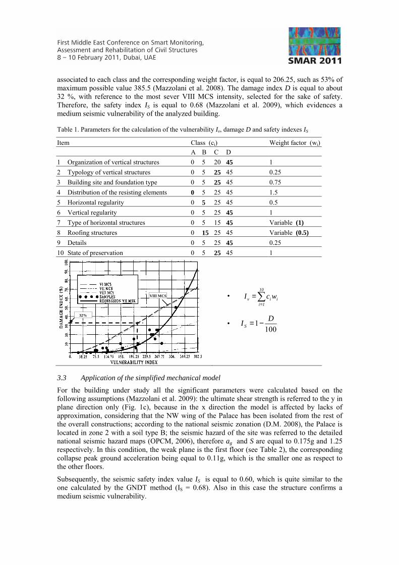
associated to each class and the corresponding weight factor, is equal to 206.25, such as 53% of maximum possible value 385.5 (Mazzolani et al. 2008). The damage index D is equal to about 32 %, with reference to the most sever VIII MCS intensity, selected for the sake of safety. Therefore, the safety index IS is equal to 0.68 (Mazzolani et al. 2009), which evidences a medium seismic vulnerability of the analyzed building.
Table 1. Parameters for the calculation of the vulnerability Iv, damage D and safety indexes IS
Item Class (ci) Weight factor (wi) A B C D 1 Organization of vertical structures 0 5 20 45 1 2 Typology of vertical structures 0 5 25 45 0.25 3 Building site and foundation type 0 5 25 45 0.75 4 Distribution of the resisting elements 0 5 25 45 1.5 5 Horizontal regularity 0 5 25 45 0.5 6 Vertical regularity 0 5 25 45 1 7 Type of horizontal structures 0 5 15 45 Variable (1) 8 Roofing structures 0 15 25 45 Variable (0.5) 9 Details 0 5 25 45 0.25 10 State of preservation 0 5 25 45 1
VIII MCS
32%
• ∑=
=10
1iiiv wcI
• 100
1 DI S −=
3.3 Application of the simplified mechanical model
For the building under study all the significant parameters were calculated based on the following assumptions (Mazzolani et al. 2009): the ultimate shear strength is referred to the y in plane direction only (Fig. 1c), because in the x direction the model is affected by lacks of approximation, considering that the NW wing of the Palace has been isolated from the rest of the overall constructions; according to the national seismic zonation (D.M. 2008), the Palace is located in zone 2 with a soil type B; the seismic hazard of the site was referred to the detailed national seismic hazard maps (OPCM, 2006), therefore ag and S are equal to 0.175g and 1.25 respectively. In this condition, the weak plane is the first floor (see Table 2), the corresponding collapse peak ground acceleration being equal to 0.11g, which is the smaller one as respect to the other floors.
Subsequently, the seismic safety index value IS is equal to 0.60, which is quite similar to the one calculated by the GNDT method (IS = 0.68). Also in this case the structure confirms a medium seismic vulnerability.

Table 2. Parameters for the calculation of the ultimate peak ground acceleration and the safety index
DIRECTION Y q e* Mi (kN) C(T) γI FSLU,i (kN) αSLU
Ground floor 1 372568 90405 0,15 First floor 0,67 217633 1,00 42375 0,11 Second floor
2,25
0,33 78387
1,95
28419 0,14
• )(* TMCe
Fqa SLU
SLU
⋅=
• gI
SLUS Sa
aI
γ=
4 CONCLUSIVE REMARKS AND FUTURE DEVELOPMENTS
The applied procedure provides significant data related to the structural behaviour of the North West wing of the Royal Palace of Naples, however the study has still to be completed. On one hand, the analysis of the timber covering structures is comprehensive, it being related to specific and confined part of the construction; on the other hand, the analysis of the vertical masonry structures is worth to be deepened. In fact, the presented vulnerability evaluation supplies only qualitative information about the state of the building, besides it is related to a part of the whole construction. In this view, as a future development, the investigations should be extended to the whole Royal Palace. In addition, analytical studies should be performed in order to identify the local weakness within the global behaviour of the overall complex structure. At the end, on the bases of the comprehensive analysis, the suitable retrofitting interventions can be designed.
REFERENCES Angeletti, P, Bellina, A, Guagenti, E, Moretti, A & Petrini, V. 1988. Comparison between vulnerability
assessment and damage index, some results. Proc. of the 9th World Conference on Earthquake Engineering, Tokyo-Kyoto, Japan.
Benedetti D, Petrini V. 1984. On seismic vulnerability of masonry buildings: proposal of an evaluation procedure. L’industria delle costruzioni; 18, 66-78 (in Italian).
Faggiano B, Marzo A, Grippa MR, Mazzolani FM. 2008. Analysis of wooden roofing structures in monumental buildings. Proc. of the 10th World Conference on the Timber Engineering (WCTE 2008), Miyazaki, Japan.
Marzo A, Faggiano B, Mazzolani FM. 2006. Analysis of wooden roofing structures in monumental buildings. Proc. of the International Conference on Structural Analysis of Historical Constructions (SAHC ’06), New Delhi, India.
Marzo A, Grippa MR, Faggiano B, Mazzolani FM. 2009. The Diplomatic Hall of the Royal Palace of Naples: diagnosis, analysis and retrofitting of the timber structures. Proc. of the Final International Conference “Protection of Hisorical Buildings (PROHITECH 09), Roma, Italy.
Mazzolani FM, Faggiano B, Marzo A. 2004. Methodology for the analysis of complex historical wooden structures: a study case. Proc. of the International Conference on Structural Analysis of Historical Constructions (SAHC ’04), Padova, Italy.
Mazzolani FM, Faggiano B, Marzo A, Guglielmo E, Mascilli Migliorini P. 2008. Seismic vulnerability of historical buildings: the Royal Palace of Naples. Proc. of the First International Symposium on Life-Cycle Civil Engineering (IALCEE’08), Varenna, Lake Como, Italy.
Mazzolani FM, Faggiano B, Marzo A, Guglielmo E, Calichio D. 2008a. Structural identification of the existing timber structures by ND methods: the Diplomatic Hall of the Royal Palace of Naples. Proc. of the National Conference on the Diagnostic for the protection and preservation of build-up materials (DIACOMAST ‘08), Caserta, Italy (in Italian).
Mazzolani FM, Faggiano B, Marzo A. 2009. Seismic vulnerability of the Royal Palace of Naples. Proc. of the National Conference on Workshop on Design for Rehabilitation of Masonry Structures (WONDER MASONRY 2009),Lacco Ameno, Ischia, Italy (in Italian).
Mazzolani FM, Faggiano B, Marzo A, Grippa MR. 2010. The ancient timber structures of the Royal Palace of Naples: diagnosis, analysis and retrofitting. Proc. of the 11th World Conference on the Timber Engineering (WCTE 2010), Riva del Garda, Trentino, Italy.