diac type 66k - docs.natlswgr.com · ge power management diac type 66k digital overcurrent relay...
TRANSCRIPT
DIAC Type 66KDIGITAL OVERCURRENT RELAY
Instruction Manual
DIAC 66K Revision: SPDV130.A03
Manual P/N: GEK-106261C
Copyright © 2000 GE Power Management
GE Power Management
215 Anderson Avenue, Markham, Ontario
Canada L6E 1B3
Tel: (905) 294-6222 Fax: (905) 294-8512
Internet: http://www.GEindustrial.com/pmManufactured under an
ISO9002 Registered system.
gGE Power Management


These instructions do not purport to cover all details or variations in equipment nor provide for every possiblecontingency to be met in connection with installation, operation, or maintenance. Should further information bedesired or should particular problems arise which are not covered sufficiently for the purchaser’s purpose, thematter should be referred to the General Electric Company.
To the extent required the products described herein meet applicable ANSI, IEEE, and NEMA standards; butno such assurance is given with respect to local codes and ordinances because they vary greatly.


GE Power Management DIAC Type 66K Digital Overcurrent Relay i
TABLE OF CONTENTS
1. INTRODUCTION 1.1 FEATURES................................................................................................ 1-11.2 ORDER CODES ........................................................................................ 1-2
2. PRODUCT DESCRIPTION 2.1 GENERAL.................................................................................................. 2-12.2 APPLICATION ........................................................................................... 2-12.3 RATINGS................................................................................................... 2-22.4 TOC FUNCTIONS ..................................................................................... 2-2
3. CALCULATION OF SETTINGS
3.1 DESCRIPTION .......................................................................................... 3-1
4. HARDWARE DESCRIPTION
4.1 CASE ......................................................................................................... 4-14.2 ADJUSTMENTS: DIGITAL UNITS............................................................. 4-14.3 ADJUSTMENTS: STANDARD INSTANTANEOUS UNIT.......................... 4-14.4 TARGETS AND INDICATORS .................................................................. 4-24.5 RESET TARGETS..................................................................................... 4-34.6 MANUAL TRIP CIRCUIT TEST................................................................. 4-34.7 TRIP CIRCUIT ........................................................................................... 4-34.8 DIAC 66K COVER INSTALLATION........................................................... 4-34.9 RECEIVING, HANDLING, AND STORAGE .............................................. 4-34.10 TARGET AND SEAL-IN UNIT ................................................................... 4-3
5. INSTALLATION 5.1 ENVIRONMENT ........................................................................................ 5-15.2 MOUNTING ............................................................................................... 5-15.3 SURGE GROUND ..................................................................................... 5-15.4 INTERNAL/EXTERNAL CONNECTIONS.................................................. 5-25.5 PANEL MOUNTING AND DRILLING ........................................................ 5-55.6 MOTOR PROTECTION CHARACTERISTIC CURVE............................... 5-6
6. ACCEPTANCE/PERIODIC TESTS
6.1 DESCRIPTION .......................................................................................... 6-16.2 VISUAL INSPECTION ............................................................................... 6-16.3 MECHANICAL INSPECTION .................................................................... 6-16.4 DRAWOUT RELAYS, GENERAL .............................................................. 6-16.5 TOC ALARM UNIT..................................................................................... 6-2
a PICKUP VERIFICATION ........................................................................ 6-2b VERIFICATION OF OPERATING TIME................................................. 6-2
6.6 TOC / INSTANTANEOUS HDO UNIT – INVERSE TIME .......................... 6-3a PICKUP VERIFICATION ........................................................................ 6-3b VERIFICATION OF OPERATING TIME................................................. 6-4
6.7 TOC / INSTANTANEOUS HDO UNIT – DEFINITE TIME ......................... 6-4a VERIFICATION OF TIME DIAL .............................................................. 6-4
6.8 INSTANTANEOUS HDO UNIT .................................................................. 6-56.9 STANDARD INSTANTANEOUS UNIT ...................................................... 6-66.10 PERIODIC TESTS..................................................................................... 6-76.11 SERVICING ............................................................................................... 6-7

ii DIAC Type 66K Digital Overcurrent Relay GE Power Management
TABLE OF CONTENTS
7. SPECIFICATIONS 7.1 BURDENS ................................................................................................. 7-17.2 RATINGS ................................................................................................... 7-27.3 ENVIRONMENTAL .................................................................................... 7-2

GE Power Management DIAC Type 66K Digital Overcurrent Relay 1- 1
GEK-106621 1 INTRODUCTION
1GEK-106621 1 INTRODUCTION 1.1 FEATURES
Figure 1–1: FRONT VIEW OF THE DIAC TYPE 66K RELAY
The DIAC Type 66K Digital Overcurrent Relay includes the following features:
• Digital single Phase overcurrent protection
• General purpose feeder protection
• 50 / 51 applications & Motor Protection
• Self powered
• 9 Selectable curves †
• Reset curve enable/disable
• Low Burden
• Fully Retrofittable
• Functional separate TOC/IOC, TOC alarm & Standard (EM) IOC operations.
• Wide settings range
• Drawout case construction
† The 66LT curve is used by this relay.

1-2 DIAC Type 66K Digital Overcurrent Relay GE Power Management
1 INTRODUCTION GEK-106621
1
Figure 1–2: FUNCTIONAL BLOCK DIAGRAM
1.2 ORDER CODES
Table 1–1: ORDER CODES FOR THE DIAC TYPE 66K RELAY
DIAC * *Base Unit DIAC | | | Base Unit – Digital Overcurrent Component Relay, “S1 Case”
ConfigurationB | |
One TOC/IOC target & seal-in; 1 TOC alarm output (max. current to 1 A); 1 standard hi-set IOC EM dual range target relay (2 to 16 A); time dial 0.1 to 9.9 sec., 50 & 60 Hz with instantaneous or timed reset plus IOC delay. Duplicates the IAC 66K function.
C | | Same as ‘B’ except one 1 standard hi-set dual range target relay unit (10 to 80 A)
D | | Same as ‘B’ except one 1 standard hi-set dual range target relay unit (20 to 160 A)
Current Rating 1 | 1 Amp Nominal Current
5 | 5 Amp Nominal Current
Revision Level B Revision Level
BLOCKDGM.CDR
52
CTs
MAIN BUSMAIN BUS
DIACType 66K
50
51
GE Power Management DIAC Type 66K Digital Overcurrent Relay 2- 1
GEK-106261 2 PRODUCT DESCRIPTION
2
GEK-106261 2 PRODUCT DESCRIPTION 2.1 GENERAL
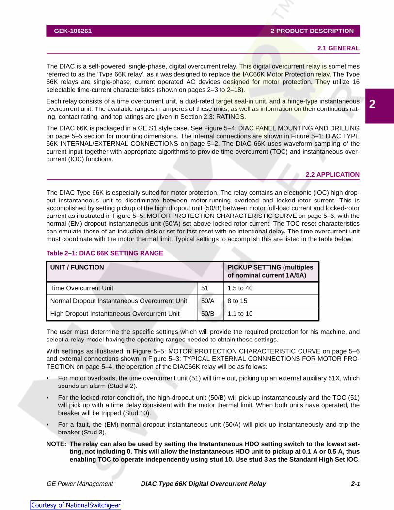
The DIAC is a self-powered, single-phase, digital overcurrent relay. This digital overcurrent relay is sometimesreferred to as the ‘Type 66K relay’, as it was designed to replace the IAC66K Motor Protection relay. The Type66K relays are single-phase, current operated AC devices designed for motor protection. They utilize 16selectable time-current characteristics (shown on pages 2–3 to 2–18).
Each relay consists of a time overcurrent unit, a dual-rated target seal-in unit, and a hinge-type instantaneousovercurrent unit. The available ranges in amperes of these units, as well as information on their continuous rat-ing, contact rating, and top ratings are given in Section 2.3: RATINGS.
The DIAC 66K is packaged in a GE S1 style case. See Figure 5–4: DIAC PANEL MOUNTING AND DRILLINGon page 5–5 section for mounting dimensions. The internal connections are shown in Figure 5–1: DIAC TYPE66K INTERNAL/EXTERNAL CONNECTIONS on page 5–2. The DIAC 66K uses waveform sampling of thecurrent input together with appropriate algorithms to provide time overcurrent (TOC) and instantaneous over-current (IOC) functions.
2.2 APPLICATION
The DIAC Type 66K is especially suited for motor protection. The relay contains an electronic (IOC) high drop-out instantaneous unit to discriminate between motor-running overload and locked-rotor current. This isaccomplished by setting pickup of the high dropout unit (50/B) between motor full-load current and locked-rotorcurrent as illustrated in Figure 5–5: MOTOR PROTECTION CHARACTERISTIC CURVE on page 5–6, with thenormal (EM) dropout instantaneous unit (50/A) set above locked-rotor current. The TOC reset characteristicscan emulate those of an induction disk or set for fast reset with no intentional delay. The time overcurrent unitmust coordinate with the motor thermal limit. Typical settings to accomplish this are listed in the table below:
The user must determine the specific settings which will provide the required protection for his machine, andselect a relay model having the operating ranges needed to obtain these settings.
With settings as illustrated in Figure 5–5: MOTOR PROTECTION CHARACTERISTIC CURVE on page 5–6and external connections shown in Figure 5–3: TYPICAL EXTERNAL CONNNECTIONS FOR MOTOR PRO-TECTION on page 5–4, the operation of the DIAC66K relay will be as follows:
• For motor overloads, the time overcurrent unit (51) will time out, picking up an external auxiliary 51X, whichsounds an alarm (Stud # 2).
• For the locked-rotor condition, the high-dropout unit (50/B) will pick up instantaneously and the TOC (51)will pick up with a time delay consistent with the motor thermal limit. When both units have operated, thebreaker will be tripped (Stud 10).
• For a fault, the (EM) normal dropout instantaneous unit (50/A) will pick up instantaneously and trip thebreaker (Stud 3).
NOTE: The relay can also be used by setting the Instantaneous HDO setting switch to the lowest set-ting, not including 0. This will allow the Instantaneous HDO unit to pickup at 0.1 A or 0.5 A, thusenabling TOC to operate independently using stud 10. Use stud 3 as the Standard High Set IOC .
Table 2–1: DIAC 66K SETTING RANGE
UNIT / FUNCTION PICKUP SETTING (multiples of nominal current 1A/5A)
Time Overcurrent Unit 51 1.5 to 40
Normal Dropout Instantaneous Overcurrent Unit 50/A 8 to 15
High Dropout Instantaneous Overcurrent Unit 50/B 1.1 to 10

2-2 DIAC Type 66K Digital Overcurrent Relay GE Power Management
2 PRODUCT DESCRIPTION GEK-106261
2
2.3 RATINGS
2.4 TOC FUNCTIONS
The TOC function operates on an ‘RMS’ current calculated from the sampled values. The IOC function oper-ates on the sampled values, and the algorithm virtually eliminates the decaying DC offset component toachieve low transient overreach of less than 7%.
The relays contain two independent settings: one for TOC and one for IOC. These two settings control theTOC/Instantaneous function of Stud 10. The TOC/Instantaneous units operate in series with each other as inthe Application Diagram shown in Figure 5–3: TYPICAL EXTERNAL CONNNECTIONS FOR MOTOR PRO-TECTION on page 5–4.
The TOC function provides 16 selectable time current curves:
The IAC51, IAC53, and IAC77 curves match the time current curve of the respective IAC model. This includesthe 0.5 through 9.9 time dial setting for the 1 and 5 A units. Numbered curves 55, 57, 66, 75, and 95 match theshape of the respective IAC model; however, the time dial positions are not one-to-one equivalents. The IEC,IEEE, and I2t curves are based on the equations listed with the corresponding curves on pages 2–11 to 2–18.
The I2t curve has a K value equal to the time dial times 250. The minimum value of K is 25 (0.1 × 250) and themaximum value is 2475 (9.9 × 250).
NOTE: IEC equations are defined by IEC 255-4 and IEEE equations are defined by IEEE PC37.112
Table 2–2: RATINGS OF TARGET AND SEAL-IN COIL
CURRENT OPERATED
UNITS DUAL-RATED AMP
0.2 AMP TAP 2.0 AMP TAP
Carry 30 amps for (seconds) 0.05 2.2
Carry 10 amps for (seconds) 0.45 2.0
Carry continuously (amperes) 0.37 2.3
Minimum operating (amperes) 0.2 2.0
Minimum dropout (amperes) 0.05 0.5
DC resistance (ohms) 8.3 0.24
60 hertz impedance (ohms) 50 0.65
50 hertz impedance (ohms) 42 0.54
• IAC51 • IEC Inverse
• IAC53 • IEC Very Inverse
• 55-SHORT TIME • IEC Extremely Inverse
• 57-MEDIUM TIME • IEEE Inverse
• 66-LONG TIME (DIAC Type 66K) • IEEE Very Inverse
• 75-SHORT TIME • IEEE Extremely Inverse
• IAC77 • Definite Time
• 95-SHORT TIME • I2T

GE Power Management DIAC Type 66K Digital Overcurrent Relay 2- 3
GEK-106261 2 PRODUCT DESCRIPTION
2
Figure 2–1: IAC51 TOC CURVE
0.1 2 3 4 55 6 7 1 2 3 4 55 6 10 2 3 4 55 6 100
0.1
2
3
4
5
66
7
1
2
3
4
5
66
7
10
2
3
4
5
66
7
100
RESET OPERATE
.5
1
2
3
4
5
6
789
9.9
Multiples of Pickup Setting
Tim
ein
Seconds
TIM
ED
IAL
SE
TT
ING
S
0.1 to 3.18 A (1 Amp Relays)
Current Range: 0.5 to 15.9 A (5 Amp Relays)

2-4 DIAC Type 66K Digital Overcurrent Relay GE Power Management
2 PRODUCT DESCRIPTION GEK-106261
2
Figure 2–2: IAC53 TOC CURVES
0.1 2 3 4 55 6 7 1 2 3 4 55 6 10 2 3 4 55 6 100
0.01
2
3
44
5
6
0.1
2
3
44
5
6
1
2
3
44
5
6
10
2
3
44
5
6
100
2
RESET OPERATE
0.5
1
2
3
4
5
6789
9.9
Multiples of Pickup Setting
TIM
ED
IAL
SE
TT
ING
S
Tim
ein
Seconds
0.1 to 3.18 A (1 Amp Relays)
Current Range: 0.5 to 15.9 A (5 Amp Relays)

GE Power Management DIAC Type 66K Digital Overcurrent Relay 2- 5
GEK-106261 2 PRODUCT DESCRIPTION
2
Figure 2–3: 55 SHORT TIME TOC CURVES
0.1 2 3 4 55 6 7 1 2 3 4 55 6 10 2 3 4 55 6 100
0.01
2
3
4
5
66
7
0.1
2
3
4
5
66
7
1
2
3
4
5
66
7
10
RESET OPERATE
0.5
1
2
3
4
5
6
78
9
9.9
Multiples of Pickup Setting
0.1 to 3.18 A (1 Amp Relays)
Current Range: 0.5 to 15.9 A (5 Amp Relays)
Tim
ein
Seconds
TIM
ED
IAL
SE
TT
ING
S

2-6 DIAC Type 66K Digital Overcurrent Relay GE Power Management
2 PRODUCT DESCRIPTION GEK-106261
2
Figure 2–4: 57 MEDIUM TIME TOC CURVES
0.1 2 3 4 55 6 7 1 2 3 4 55 6 10 2 3 4 55 6 100
0.1
2
3
4
5
66
7
1
2
3
4
5
66
7
10
2
3
4
5
66
7
100
RESET OPERATE
.5
1
2
3
4
5
6
7899.9
Multiples of Pickup Setting
0.1 to 3.18 A (1 Amp Relays)
Current Range: 0.5 to 15.9 A (5 Amp Relays)
TIM
ED
IAL
SE
TT
ING
S

GE Power Management DIAC Type 66K Digital Overcurrent Relay 2- 7
GEK-106261 2 PRODUCT DESCRIPTION
2
Figure 2–5: 66 LONG TIME TOC CURVES
0.1 2 3 4 55 6 7 1 2 3 4 55 6 10 2 3 4 55 6 100
0.1
2
3
4
55
6
1
2
3
4
55
6
10
2
3
4
55
6
100
2
3
4
55
6
1000
RESET OPERATE
0.5
1
2
3
4
5
67899.9
Multiples of Pickup Setting
Tim
ein
Seconds
0.1 to 3.18 A (1 Amp Relays)
Current Range: 0.5 to 15.9 A (5 Amp Relays)
TIM
ED
IAL
SE
TT
ING
S

2-8 DIAC Type 66K Digital Overcurrent Relay GE Power Management
2 PRODUCT DESCRIPTION GEK-106261
2
Figure 2–6: 75 SHORT TIME TOC CURVES
0.1 2 3 4 55 6 7 1 2 3 4 55 6 10 2 3 4 55 6 100
0.01
2
3
4
55
6
0.1
2
3
4
55
6
1
2
3
4
55
6
10
2
3
4
55
6
100
RESET OPERATE
0.5
1
2
3
4
5
6
7899.9
Multiples of Pickup Setting
Tim
ein
Seconds
TIM
ED
IAL
SE
TT
ING
S
0.1 to 3.18 A (1 Amp Relays)
Current Range: 0.5 to 15.9 A (5 Amp Relays)

GE Power Management DIAC Type 66K Digital Overcurrent Relay 2- 9
GEK-106261 2 PRODUCT DESCRIPTION
2
Figure 2–7: IAC77 TOC CURVES
0.1 2 3 4 55 6 7 1 2 3 4 55 6 10 2 3 4 55 6 100
0.01
2
3
44
5
6
0.1
2
3
44
5
6
1
2
3
44
5
6
10
2
3
44
5
6
100
2
RESET OPERATE
0.5
1
2
3
4
5
6
7
9.9
98
Multiples of Pickup Setting
0.1 to 3.18 A (1 Amp Relays)
Current Range: 0.5 to 15.9 A (5 Amp Relays)
TIM
ED
IAL
SE
TT
ING
S
Tim
ein
Seconds

2-10 DIAC Type 66K Digital Overcurrent Relay GE Power Management
2 PRODUCT DESCRIPTION GEK-106261
2
Figure 2–8: 95 SHORT TIME TOC CURVES
0.1 2 3 4 55 6 7 1 2 3 4 55 6 10 2 3 4 55 6 100
0.01
2
3
4
55
6
0.1
2
3
4
55
6
1
2
3
4
55
6
10
2
3
4
55
6
100
RESET OPERATE
0.5
1
2
3
4
5
67899.9
Multiples of Pickup Setting
0.1 to 3.18 A (1 Amp Relays)
Current Range: 0.5 to 15.9 A (5 Amp Relays)
Tim
ein
Seconds
TIM
ED
IAL
SE
TT
ING
S

GE Power Management DIAC Type 66K Digital Overcurrent Relay 2- 11
GEK-106261 2 PRODUCT DESCRIPTION
2
RESET TIME: ; PICKUP TIME:
Figure 2–9: IEC INVERSE TOC CURVES
0.1 2 3 4 55 6 7 1 2 3 4 55 6 10 2 3 4 55 6 100
0.01
2
3
4
55
6
0.1
2
3
4
55
6
1
2
3
4
55
6
10
2
3
4
55
6
100
RESET OPERATE
3
2
1
0.5
4
5
6789
9.9
Multiples of Pickup Setting
0.1 to 3.18 A (1 Amp Relays)
Current Range: 0.5 to 15.9 A (5 Amp Relays)
Tim
ein
Seconds
TIM
ED
IAL
SE
TT
ING
S
t TD 0.97
M 2 1–------------------
⋅= t TD 0.014
M 0.02 1–------------------------
⋅=

2-12 DIAC Type 66K Digital Overcurrent Relay GE Power Management
2 PRODUCT DESCRIPTION GEK-106261
2
RESET TIME: ; PICKUP TIME:
Figure 2–10: IEC VERY INVERSE TOC CURVES
0.1 2 3 4 55 6 7 1 2 3 4 55 6 10 2 3 4 55 6 100
0.01
2
3
44
5
6
0.1
2
3
44
5
6
1
2
3
44
5
6
10
2
3
44
5
6
100
2
RESET OPERATE
0.5
1
2
3
4
56
9.9
789
Multiples of Pickup Setting
0.1 to 3.18 A (1 Amp Relays)
Current Range: 0.5 to 15.9 A (5 Amp Relays)
Tim
ein
Seconds
TIM
ED
IAL
SE
TT
ING
S
t TD 4.32
M 2 1–------------------
⋅= t TD 1.35M 1–--------------
⋅=

GE Power Management DIAC Type 66K Digital Overcurrent Relay 2- 13
GEK-106261 2 PRODUCT DESCRIPTION
2
RESET TIME: ; PICKUP TIME:
Figure 2–11: IEC EXTREMELY INVERSE TOC CURVES
0.1 2 3 4 55 6 7 1 2 3 4 55 6 10 2 3 4 55 6 100
0.01
2
3
44
5
6
0.1
2
3
44
5
6
1
2
3
44
5
6
10
2
3
44
5
6
100
2
RESET OPERATE
0.5
9.99876
5
4
3
2
1
Multiples of Pickup Setting
0.1 to 3.18 A (1 Amp Relays)
Current Range: 0.5 to 15.9 A (5 Amp Relays)
Tim
ein
Seconds
TIM
ED
IAL
SE
TT
ING
S
t TD 5.82
M 2 1–------------------
⋅= t TD 8.0
M 2 1–------------------
⋅=

2-14 DIAC Type 66K Digital Overcurrent Relay GE Power Management
2 PRODUCT DESCRIPTION GEK-106261
2
RESET TIME: ; PICKUP TIME:
Figure 2–12: IEEE INVERSE TOC CURVES
0.1 2 3 4 55 6 7 1 2 3 4 55 6 10 2 3 4 55 6 100
0.01
2
3
4
55
6
0.1
2
3
4
55
6
1
2
3
4
55
6
10
2
3
4
55
6
100
RESET OPERATE
0.5
1
2
3
4
5
67899.9
Multiples of Pickup Setting
0.1 to 3.18 A (1 Amp Relays)
Current Range: 0.5 to 15.9 A (5 Amp Relays)
Tim
ein
Seconds
TIM
ED
IAL
SE
TT
ING
S
t TD 0.97
M 2 1–------------------
⋅= t TD 0.013
M 0.02 1–------------------------ 0.0228+
⋅=

GE Power Management DIAC Type 66K Digital Overcurrent Relay 2- 15
GEK-106261 2 PRODUCT DESCRIPTION
2
RESET TIME: ; PICKUP TIME:
Figure 2–13: IEEE VERY INVERSE TOC CURVES
0.1 2 3 4 55 6 7 1 2 3 4 55 6 10 2 3 4 55 6 100
0.01
2
3
44
5
6
0.1
2
3
44
5
6
1
2
3
44
5
6
10
2
3
44
5
6
100
2
RESET OPERATE
0.5
1
2
3
4
5
67899.9
Multiples of Pickup Setting
0.1 to 3.18 A (1 Amp Relays)
Current Range: 0.5 to 15.9 A (5 Amp Relays)
TIM
ED
IAL
SE
TT
ING
S
Tim
ein
Seconds
t TD 4.32
M 2 1–------------------
⋅= t TD 3.922
M 2 1–------------------ 0.0982+
⋅=

2-16 DIAC Type 66K Digital Overcurrent Relay GE Power Management
2 PRODUCT DESCRIPTION GEK-106261
2
RESET TIME: ; PICKUP TIME:
Figure 2–14: IEEE EXTREMELY INVERSE TOC CURVES
0.1 2 3 4 55 6 7 1 2 3 4 55 6 10 2 3 4 55 6 100
0.01
2
3
44
5
6
0.1
2
3
44
5
6
1
2
3
44
5
6
10
2
3
44
5
6
100
2
RESET OPERATE
0.5
1
2
3
4
567899.9
Multiples of Pickup Setting
0.1 to 3.18 A (1 Amp Relays)
Current Range: 0.5 to 15.9 A (5 Amp Relays)
TIM
ED
IAL
SE
TT
ING
S
Tim
ein
Seconds
t TD 5.82
M 2 1–------------------
⋅= t TD 5.64
M 2 1–------------------ 0.02434+
⋅=

GE Power Management DIAC Type 66K Digital Overcurrent Relay 2- 17
GEK-106261 2 PRODUCT DESCRIPTION
2
Figure 2–15: DEFINITE TIME
0.1 2 3 4 55 6 7 1 2 3 4 55 6 10 2 3 4 55 6 100
3
4
55
6
7
0.1
2
3
4
55
6
7
1
2
3
4
55
6
7
10
2
3
4
55
6
7
100
RESET
OPERATE
0.5
1
2
4
5
67899.9
3
Multiples of Pickup Setting
0.1 to 3.18 A (1 Amp Relays)
Current Range: 0.5 to 15.9 A (5 Amp Relays)
TIM
ED
IAL
SE
TT
ING
S
Tim
ein
Seconds

2-18 DIAC Type 66K Digital Overcurrent Relay GE Power Management
2 PRODUCT DESCRIPTION GEK-106261
2
RESET TIME: ; PICKUP TIME:
Figure 2–16: I 2T TIME CURVE
0.1 2 3 4 55 6 7 1 2 3 4 55 6 10 2 3 4 55 6 100
0.1
2
3
44
5
1
2
3
44
5
10
2
3
44
5
100
2
3
44
5
1000
2
3
RESET OPERATE
0.5
1
2
3
4
5
67899.9
Multiples of Pickup Setting
0.1 to 3.18 A (1 Amp Relays)
Current Range: 0.5 to 15.9 A (5 Amp Relays)
TIM
ED
IAL
SE
TT
ING
S
Tim
ein
Seconds
t TD 250
M 2 1–------------------
⋅= t TD 250
M 2----------
⋅=

GE Power Management DIAC Type 66K Digital Overcurrent Relay 2- 19
GEK-106261 2 PRODUCT DESCRIPTION
2
Figure 2–17: IOC CURVE FOR THE HDO INSTANTANEOUS UNIT
Figure 2–18: STANDARD (EM) INSTANTANEOUS UNIT
Multples of Pickup Setting
20
30
40
50
60
70
80
90
100
1 2 3 4 5 6 7 8 9 101.51.1
Tim
ein
Mill
iseconds
0.1 to 3.18 A (1 Amp Relays)
Current Range: 0.5 to 15.9 A (5 Amp Relays)

2-20 DIAC Type 66K Digital Overcurrent Relay GE Power Management
2 PRODUCT DESCRIPTION GEK-106261
2
Figure 2–19: IOC CURVE FOR THE STANDARD (EM) INSTANTANEOUS UNIT

GE Power Management DIAC Type 66K Digital Overcurrent Relay 3- 1
GEK-106261 3 CALCULATION OF SETTINGS
3
GEK-106261 3 CALCULATION OF SETTINGS 3.1 DESCRIPTION
When replacing IAC 66K relays, review the time current curves of the digital relays to verify that they conformto the relays being replaced. In some cases it may be necessary to redo the coordination study to assure coor-dination with other devices.
The base time of the Definite Time Curve is 1 second. The base time is multiplied by the time dial to providethe actual operating time. The default or lowest time dial setting for the Definite Time Curve is 0.1.
The I2T curve has a K value of 250 @ time dial of 1. The range is from 25 to 2475 in steps of 25 set by the timedial. The default or lowest time dial setting for the I2T curve is 0.1.
Pickup for the TOC/ Inst unit is settable from 0.5 to 15.9 amps in 0.1 amp increments for the 5 amp model, and0.1 to 3.18 amps in 0.02 amp increments for the 1 amp model, a setting of 0 disables the TOC element. Thetime dial can be set from 0.5 to 9.9 in 0.1 increments on both the 5 amp model and the 1 amp model. The onlyexception is for the Definite Time and I2T curves where 0.1 is the minimum value.
The IOC function is settable from 1 to 159 amps in 1 amp increments for the 5 amp model, and 0.2 to 31.8amps in increments of 0.2 amps for the 1 amp model. Setting the pickup to 0 disables the IOC element. Bothmodels have an IOC delay adjustment from 50 to 400 milliseconds in 25 millisecond steps.
The formula is:
IOC delay (in milliseconds) = DS × 25 + 25
where DS is setting on IOC delay dial.
The TOC reset characteristic can be controlled from the front panel. The TOC reset can be set to “timed reset”which emulates the characteristic of an induction disk relay, or “instantaneous reset” where the reset is fixed at40 to 50 milliseconds.
The system frequency can be set for 50 or 60 Hz controlled from the front panel.
The High Set Standard (EM) Instantaneous unit pickup range can be adjusted continuously over a four to onerange by using the adjustable pose piece. When the top of the core is lined up with the calibration stamping, anapproximate value of pickup can be determined. Dropout is at least 40 to 50 percent of pickup.

3-2 DIAC Type 66K Digital Overcurrent Relay GE Power Management
3 CALCULATION OF SETTINGS GEK-106261
3

GE Power Management DIAC Type 66K Digital Overcurrent Relay 4- 1
GEK-106621 4 HARDWARE DESCRIPTION
4
GEK-106621 4 HARDWARE DESCRIPTION 4.1 CASE
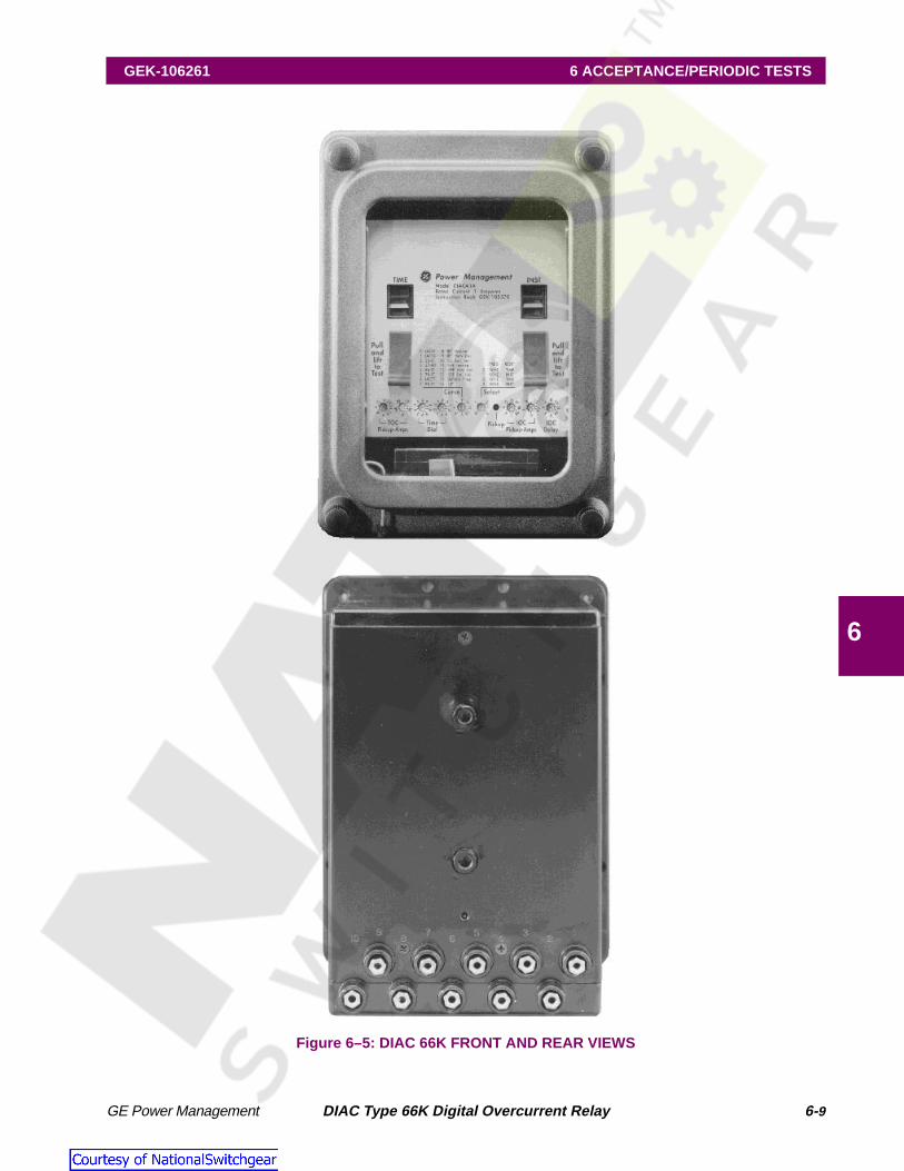
The DIAC relay consists of a case, cover, support structure, and a connection plug to make up the electricalconnection. The case is shown in Figure 6–5: DIAC 66K FRONT AND REAR VIEWS on page 6–9. The exter-nal connections are shown in Figure 5–3: TYPICAL EXTERNAL CONNNECTIONS FOR MOTOR PROTEC-TION on page 5–4. It has 10 connection points and a CT shorting bar. As the connection plug is withdrawn, thetrip circuit is broken prior to the current shorting bar engagement.
4.2 ADJUSTMENTS: DIGITAL UNITS
All customer settings for the TOC Alarm and TOC/IOC are accessible from the front of the relay. The relaycover must be removed to gain access to the settings. The cover has provisions for a sealing “wire.” The set-tings are left to right, pickup current level for the time element, time dial, curve selection, frequency/reset time,pickup current level for the instantaneous element, and the instantaneous element time delay. The settings areall calibrated and are set by turning the rotary switch to the desired value. The switches are recessed, a smallscrew driver is required to make the adjustment.
The relay may be supplied with one of three pointer styles as shown. The color is the color of the indicator, notethe arrow location, all switches are shown in the 9:00 position.
Figure 4–1: DIAC 66K POINTER STYLES
The TOC pickup current is set directly in Amps with two rotary switches. An arrow is used to indicate settingposition. Setting the TOC or the IOC pickup current between, but not including 0 and a value less than mini-mum 0.5 (5amp) or 0.1 (1Amp) will result in the relay defaulting to its minimum setting. Setting the TOC or IOCpickup current to 0 will disable their respective elements. Although the time dial can be set to a value less thanminimum the relay will use the minimum setting.
4.3 ADJUSTMENTS: STANDARD INSTANTANEOUS UNIT
The standard instantaneous unit is an electromagnet that attracts a hinged armature when sufficient current isapplied. The armature carries a “T” shaped moving contact that bridges two stationary contacts when the coil isenergized. A target is displayed when the unit operated. Pressing the button in the lower left corner of the relaycover resets the target.
The pickup range can be adjusted continuously over a four to one range by using the adjustable pole piece.When the top of the core is lined up with the calibration stamping, an approximate value of pickup can bedetermined. Dropout is about 40 to 50 percent of pickup.
Figure 2–19: IOC CURVE FOR THE STANDARD (EM) INSTANTANEOUS UNIT on page 2–20 shows the vari-ation of operating time with applied current for this unit. Burden data of the standard unit is given the tablebelow.
Pointer styles
Yellow Orange White

4-2 DIAC Type 66K Digital Overcurrent Relay GE Power Management
4 HARDWARE DESCRIPTION GEK-106621
4
† Volt-Amperes at five amps calculated from input at minimum pickup ( I2Z).
4.4 TARGETS AND INDICATORS
The yellow pick-up LED, will come on solid for the TOC function when the input current to the relay is higherthan the set point. The location of the LED is between the frequency/reset switch and the IOC pickup levelswitch.
It may be desirable to know when the relay is powered up and operating. The relay must be energized at orabove 95% of the minimum possible setting and below pick-up set point. To activate, turn the SELECT switchone step clockwise or one step counterclockwise. This will cause the pickup LED to blink at 4 second intervalswhile current is below the pick-up set point. Minimum current is 95% of minimum TOC pickup setting for boththe 1amp and 5 amp models. A blinking LED indicates the microprocessor is executing code and outputtingsignals.
The relay uses a target and seal-in unit as its TOC/IOC tripping element. And the relay uses one target for thehigh set standard IOC unit. The targets are mechanically latched when the function trips. The TOC/IOC con-tacts will remain closed until the trip circuit current drops below 0.19 or 2.0 Amps, depending on the Seal-In tapsetting.
NOTE: The current will continue conducting through Stud 1 to Stud 10 while the trip signal is stillbeing sent to the TOC/Inst. Unit.
Table 4–1: DIAC 66K BURDEN DATA
Pickup Range (A)
Frequency (Hz)
Amps Volt-Amps † Impedance(Ω)
Power Factor
0.5 to 2 50 5 310 12.4 0.84
60 5 330 13.2 0.78
1 to 4 50 5 94 3.75 0.77
60 5 100 4.0 0.71
2 to 8 50 5 23 0.94 0.77
60 5 25 1.0 0.71
4 to 16 50 5 5.8 0.23 0.77
60 5 6.2 0.25 0.71
10 to 40 50 5 0.9 0.04 0.77
60 5 1.0 0.04 0.71
20 to 80 50 5 0.23 0.01 0.77
60 5 0.25 0.01 0.71
40 to 60 50 5 0.07 0.003 0.71
60 5 0.07 0.003 0.71

GE Power Management DIAC Type 66K Digital Overcurrent Relay 4- 3
GEK-106621 4 HARDWARE DESCRIPTION
4
4.5 RESET TARGETS
Targets can be reset by lifting the target reset level at the lower left edge of the cover on the DIAC. The relayalso provides a front panel trip circuit test. A actuating lever that must be pulled and then lifted is provided totrip the device connected to the relay. The level directly operates the trip contacts.
4.6 MANUAL TRIP CIRCUIT TEST
The front panel contains two manual trip levers to test the trip circuit. The relay cover must be removed toaccess the lever. The lever must be pulled and then lifted which prevents unintentional uplifted to prevent unin-tentional operation.
4.7 TRIP CIRCUIT
The trip circuit is NOT polarity sensitive. The trip circuit will not be damaged if connected in reverse.
NOTE: Both trip circuits are suitable for use with Cap-Trip devices.
4.8 DIAC 66K COVER INSTALLATION
When replacing the cover on the DIAC relays the reset wire should be “locked” behind the nameplate by aslight left to right motion to place the reset wire in the correct position.
4.9 RECEIVING, HANDLING, AND STORAGE
Immediately upon receipt, the relay should be unpacked and examined for any damage sustained during ship-ment. If damage occurred during shipment a damage claim should be filed at once with the transportation com-pany, and the nearest GE sales office should be notified. If the relay is not installed immediately, it should bestored in its original carton in a location that is dry and protected from dust, metallic chips and severe atmo-spheric conditions.
4.10 TARGET AND SEAL-IN UNIT
The target and seal-in unit has an operating coil tapped at 0.2 and 2.0 amperes. The relay is shipped from thefactory with the tap screw in the lower-ampere position. The tap screw is the screw holding the right-hand sta-tionary contact. To change the tap setting, first remove one screw from the left-hand stationary contact andplace it in the desired tap. Next, remove the screw from the first undesired tap, and place it on the left-hand sta-tionary contact where the first screw was removed. This is shown below in Figure 4–2: OPERATING COILTAPPED AT 2A (FACTORY DEFAULT). This procedure is necessary to prevent the right-hand stationary con-tact from getting out of adjustment.
NOTE: Screws should never be left in both taps at the same time!

4-4 DIAC Type 66K Digital Overcurrent Relay GE Power Management
4 HARDWARE DESCRIPTION GEK-106621
4
Figure 4–2: OPERATING COIL TAPPED AT 2A (FACTORY DEFAULT)
0.2 A SETTING2 A SETTING
0.2 A SETTING0.2 A SETTING

GE Power Management DIAC Type 66K Digital Overcurrent Relay 5- 1
GEK-106261 5 INSTALLATION
5
GEK-106261 5 INSTALLATION 5.1 ENVIRONMENT
Installation of the relay should be in a clean dry location that is free from dust.
5.2 MOUNTING
The relay should be securely mounted on a vertical surface that provides accessibility to both the front and rearof the unit. The outline and panel drilling dimensions are provided in Figure 5–4: DIAC PANEL MOUNTINGAND DRILLING on page 5–5.
5.3 SURGE GROUND
The relay should be grounded to the station ground mat with a 12 AWG braided ground lead connected to ter-minal 4. If the relay is to be retrofitted in a panel, terminal 4 should be removed from the new case and installedinto the old case. For the surge protection to function properly the relay must be grounded.

5-2 DIAC Type 66K Digital Overcurrent Relay GE Power Management
5 INSTALLATION GEK-106261
5
5.4 INTERNAL/EXTERNAL CONNECTIONS
Figure 5–1: DIAC TYPE 66K INTERNAL/EXTERNAL CONNECTIONS

GE Power Management DIAC Type 66K Digital Overcurrent Relay 5- 3
GEK-106261 5 INSTALLATION
5
Figure 5–2: IAC TYPE 66K INTERNAL CONNECTIONS DIAGRAM (FOR REFERENCE)
1
6
5
4
2
9
10
C
D
A
B
6A
INSULATEDSTAND OFF
INSTANTANEOUSUNIT
INDUCTION UNIT
SEAL-INUNIT
** SHORT F INGER
** ** ** **
NOTE: Instantaneous unit connections are for range operation.For high range operation, connect B and D to terminal no. 6 and
A and C to terminal no. 4

5-4 DIAC Type 66K Digital Overcurrent Relay GE Power Management
5 INSTALLATION GEK-106261
5
Figure 5–3: TYPICAL EXTERNAL CONNNECTIONS FOR MOTOR PROTECTION

GE Power Management DIAC Type 66K Digital Overcurrent Relay 5- 5
GEK-106261 5 INSTALLATION
5
5.5 PANEL MOUNTING AND DRILLING
Figure 5–4: DIAC PANEL MOUNTING AND DRILLING
6.625
PANEL
CASE
.75
3.0
STUDNUMBERING
13579
10 8 6 4 2
6.187
5.687
2.187
4.375 8.812CUTOUT
.500
(TYPICAL)
5.25
5/8 DRILLCUTOUT MAY REPLACE
DRILLED HOLES
GLASS
(4) 10-32 X 3/8
MTG. SCREWS
.218
2 HOLES
1.46837MM
133MM 12MM
3/4 DRILL10 HOLES
5MM
224MM
56MM
112MM
168MM
29MM 19MM
157MM
9.125232MM
4.406112MM
3.90699MM
76MM
1.125
144MM
BACK VIEW
CL
LC LC
15MM
19MM
MTG.MTG.SEMI-FLUSH SURFACE (2) 5/16-18 STUDS
FOR SURFACE MTG.
10-32STUDS
8.375212MM
76MM
VIEW SHOWING ASSEMBLY OF HARDWAREFOR SURFACE MTG. ON STEEL PANELS
PANEL DRILLINGFOR SEMI-FLUSH MOUNTING
FRONT VIEW
5/16-18 STUD
PANEL DRILLINGFOR SURFACE MOUNTING
FRONT VIEW
1/4 DRILL4 HOLES6MM
2.84372MM
1.15629MM
109MM
.2506MM
3.076MM
.71818MM
4.281
3.0
5MM.218

5-6 DIAC Type 66K Digital Overcurrent Relay GE Power Management
5 INSTALLATION GEK-106261
5
5.6 MOTOR PROTECTION CHARACTERISTIC CURVE
Figure 5–5: MOTOR PROTECTION CHARACTERISTIC CURVE

GE Power Management DIAC Type 66K Digital Overcurrent Relay 6- 1
GEK-106261 6 ACCEPTANCE/PERIODIC TESTS
6
GEK-106261 6 ACCEPTANCE/PERIODIC TESTS 6.1 DESCRIPTION
Immediately upon receipt of the relay, an inspection and acceptance test should be made to make sure that nodamage has been sustained in shipment, and that the relay calibrations have not been disturbed.
6.2 VISUAL INSPECTION
Check the nameplate stamping to make sure that the model number and rating of the relay agree with the req-uisition. Remove the relay from its case and check that there are no broken or cracked molded parts or othersigns of physical damage, and that all screws are tight.
6.3 MECHANICAL INSPECTION
1. The target and seal-in unit, pull and lift the TOC/Instantaneous HDO lever to test the target, repeat the testfor the IOC Standard High Set target. The Target flag should re-main when the lever is released. Reset thetarget by pushing the reset bar.
2. Make sure that the fingers and shorting bars agree with the internal connections diagram.
CAUTION: Every circuit in the drawout case has an auxiliary brush. It is especially important on cur-rent circuits and other circuits with shorting bars that auxiliary brush be bent high enoughto engage
6.4 DRAWOUT RELAYS, GENERAL
Since all drawout relays in service operate in their cases, it is recommended that they be tested in their casesor an equivalent case. A relay may be tested without removing it from the panel by using the appropriate testplug. For an S case use the XLA series test plug, refer to the GE Power Management Product Catalog, Prod-ucts CD, or website (the URL is www.ge.com/indsys/pm). Although the test plugs provide greater flexibility, itre-quires CT shorting jumpers and exercise of greater care since connections are made to both the relay andthe external circuitry.
NOTE: Pickup calibration for any of the digital controlled outputs are calibrated by the factory and arenot user set-able. Also the same electronics sample the analog signals whether TOC or IOCwith the only difference being the software calculations.

6-2 DIAC Type 66K Digital Overcurrent Relay GE Power Management
6 ACCEPTANCE/PERIODIC TESTS GEK-106261
6
6.5 TOC ALARM UNIT
The TOC Alarm unit Is designed to operate an external alarm unit or auxiliary relay which can draw a maximumof 1 Amp continuously.
a) PICKUP VERIFICATION
• Connect the relay as indicated in Figure 6–1: TOC ALARM UNIT TEST SETUP. In order to apply current tothe relay, use a 50/60 Hz voltage source, with a variable resistor in series, or an electronic current source.
• Set the relay at the desired pickup TOC and the Instantaneous HDO unit by setting the instantaneous cur-rent setting to zero.
Apply current to the relay and verify that the Pickup LED on the front of the relay lights between 98% and 102%of the pickup TOC setting. If the relay is set to blink between power up and pickup, please set it not to blink.
Reduce the current applied, verifying that at a value between 95% and 100% of the pickup TOC, the relayPickup LED turns off or blinks if set to blink.
Figure 6–1: TOC ALARM UNIT TEST SETUP
b) VERIFICATION OF OPERATING TIME
Because the Digital self powered series of relays has many different curve characteristics, the basic testinstruction will be given and the data for each of the curves can be found in Table 6–1: PICKUP TIMES FORVARYING MULTIPLES OF PICKUP (MPU) on page 6–3. With the relay still connected as indicated in Figure6–1: TOC ALARM UNIT TEST SETUP, set the time overcurrent unit to minimum pickup and set the corre-sponding time dial to 5.
Successively apply currents of 2, 5, and 10 times pickup TOC, verifying that the operating times are within themargins indicated in Table 6–1: PICKUP TIMES FOR VARYING MULTIPLES OF PICKUP (MPU)
SINGLEPHASE
CURRENTSOURCE
TIMER
T2
T1
DIAC TYPE66K
TOCAlarm
Iin
T6
T5
START STOP
36/300 V DCPOWERSUPPLY
CURRENTLIMITED TO
200 mA
–
+
200 mA
1 K Ω

GE Power Management DIAC Type 66K Digital Overcurrent Relay 6- 3
GEK-106261 6 ACCEPTANCE/PERIODIC TESTS
6
6.6 TOC / INSTANTANEOUS HDO UNIT – INVERSE TIME
The TOC/ Instantaneous HDO unit is designed similarly to a hinged armature instantaneous unit.
a) PICKUP VERIFICATION
• Connect the relay as indicated in Figure 6–2: DIAC 66K TOC INVERSE TIME TEST SETUP. In order toapply current to the relay, use a 50/60 Hz voltage source, with a variable resistor in series, or an electroniccurrent source.
• Set the TOC unit at the desired pickup and the Instantaneous HDO unit by setting the Instantaneous cur-rent pickup to lowest possible setting not including zero. This will allow the Instantaneous HDO unit tooperate without affecting the TOC trip time which is coordinated with the Instantaneous HDO unit.
Apply current to the relay and verify that the Pickup LED on the front of the relay lights between 98% and 102%of the pickup TOC setting. If the relay is set to blink between power up and pickup, please set it not to blink.
Reduce the current applied, verifying that at a value between 95% and 100% of the pickup TOC, the relayPickup LED turns off or blinks if set to blink.
Table 6–1: PICKUP TIMES FOR VARYING MULTIPLES OF PICKUP (MPU)
CURVE PICKUP TIMES (IN SECONDS)
2 MPU 5 MPU 10 MPU
IAC 51 3.62 to 4.05 1.69 to 1.86 1.19 to 1.32
IAC 53 6.66 to 7.36 1.25 to 1.37 0.687 to 0.759
55-ST 0.298 to 0.330 0.155 to 0.170 0.133 to 0.140
57-MT 20.40 to 22.62 8.82 to 9.75 5.7 to 6.3
66-LT (Type 66K) † 42.7 to 47.2 17.28 to 19.10 10.78 to 11.90
75-ST 0.748 to 0.827 0.3113 to 0.3440 0.2440 to 0.2707
IAC 77 6.49 to 7.17 0.859 to 0.954 0.266 to 0.296
95-ST 0.895 to 0.994 0.356 to 0.396 0.276 to 0.303
IEEE Inverse 3.59 to 3.99 1.59 to 1.76 1.12 to 1.25
IEEE Very Inverse 6.51 to 7.24 1.21 to 1.34 0.64 to 0.71
IEEE Extremely Inverse 8.76 to 9.73 1.18 to 1.32 0.374 to 0.412
IEC Inverse 4.73 to 5.26 2.00 to 2.22 1.39 to 1.54
IEC Very Inverse 6.310 to 7.014 1.56 to 1.73 0.690 to 0.768
IEC Extremely Inverse 12.3 to 13.7 1.51 to 1.67 0.369 to 0.410
Definite Time 4.71 to 5.24 4.71 to 5.24 4.71 to 5.21
I2T 1.175 to 1.310 0.191 to 0.212 0.051 to 0.056
† TD = 5

6-4 DIAC Type 66K Digital Overcurrent Relay GE Power Management
6 ACCEPTANCE/PERIODIC TESTS GEK-106261
6
Figure 6–2: DIAC 66K TOC INVERSE TIME TEST SETUP
b) VERIFICATION OF OPERATING TIME
Because the Digital self powered series of relays has many different curve characteristics, the basic testinstruction will be given and the data for each of the curves can be found in Table 6–1: PICKUP TIMES FORVARYING MULTIPLES OF PICKUP (MPU) on page 6–3. With the relay still connected as indicated in Figure6–2: DIAC 66K TOC INVERSE TIME TEST SETUP, set the time overcurrent unit to minimum pickup and setthe corresponding time dial to 5. Enable the Instantaneous HDO settings by setting the pickup to the lowestsetting (not including zero). This allows the TOC function to operate without coordinating with the Instanta-neous HDO unit. Successively apply currents of 2, 5, and 10 times pickup TOC, verifying that the operatingtimes are within the margins indicated in Table 6–1: PICKUP TIMES FOR VARYING MULTIPLES OF PICKUP(MPU) on page 6–3.
6.7 TOC / INSTANTANEOUS HDO UNIT – DEFINITE TIME
For the Definite Time Characteristics, based on any current input, the time should be half of the maximumvalue.
a) VERIFICATION OF TIME DIAL
Set the relay at the minimum pickup TOC and verify that with an input current of five times (5x) pickup TOC, theoperating time is between the margins shown in Table 6–2: PICKUP TIMES FOR VARYING TIME DIALS.
SINGLEPHASE
CURRENTSOURCE
TIMER
T10
T1
DIAC TYPE66K
Target &Seal -in
Iin
T6
T5
START STOP
36/300 V DCPOWERSUPPLY
CURRENTLIMITED TO
200 mA
To Test Seal-InFunction
–
+

GE Power Management DIAC Type 66K Digital Overcurrent Relay 6- 5
GEK-106261 6 ACCEPTANCE/PERIODIC TESTS
6
6.8 INSTANTANEOUS HDO UNIT
The instantaneous HDO unit will react differently depending on how the signal is applied. If the signal is appliedsuddenly with no prefault current, the operating time will be longer. If a prefault current is applied prior to thefault the operating time will be shorter. The following test determines that the instantaneous unit is working cor-rectly and confirms the operating time for faults applied with no prefault current.
Connect the relay as shown in Figure 6–2: DIAC 66K TOC INVERSE TIME TEST SETUP on page 6–4. Setthe instantaneous unit pickup to 2 Amps (for the 5 Amp rated relay) or 0.4 Amps (for the 1 Amp rated relay)with a zero IOC delay setting. Also set the TOC pickup to its lowest setting not including zero. This allows theInstantaneous HDO unit to function without coordinating with the TOC unit. Apply 6 Amps (for the 5 Amp ratedrelay) or 1.2 Amps (for the 1 Amp rated relay) and measure the operating time. The operating time should bebetween 32ms and 46ms. This time is subject to dependent on the multiple of pickup current and the fault inci-dence angle. A graph of how the instantaneous unit varies as a function of input current is provided for refer-ence in Figure 2–17: IOC CURVE FOR THE HDO INSTANTANEOUS UNIT on page 2–19.
Table 6–2: PICKUP TIMES FOR VARYING TIME DIALS
CURVE PICKUP TIMES (IN SECONDS) FOR TIME DIAL SETTINGS
10 7 3 1
IAC 51 3.62 to 4.05 2.42 to 2.69 0.996 to 1.106 0.372 to 0.413
IAC 53 2.73 to 3.03 1.78 to 1.98 0.742 to 0.824 0.025 to 0.028
55-ST 0.29 to 0.32 0.21 to 0.23 0.10 to 0.12 0.058 to 0.064
57-MT 17.3 to 19.3 12.20 to 13.65 5.27 to 5.86 1.783 to 1.980
66-LT (Type 66K) † 33.9 to 37.7 24.1 to 26.7 10.3 to 11.4 3.460 to 3.848
75-ST 0.577 to 0.641 0.424 to 0.471 0.200 to 0.221 0.09 to 0.10
IAC 77 1.810 to 2.013 1.20 to 1.33 0.545 to 0.605 0.228 to 0.253
95-ST 0.690 to 0.767 0.490 to 0.544 0.230 to 0.252 0.102 to 0.110
IEEE Inverse 3.108 to 3.450 2.206 to 2.450 0.95 to 1.06 0.345 to 0.384
IEEE Very Inverse 2.390 to 2.635 1.69 to 1.88 0.745 to 0.828 0.273 to 0.304
IEEE Extremely Inverse 2.32 to 2.58 1.65 to 1.84 0.734 to 0.815 0.266 to 0.296
IEC Inverse 3.94 to 4.37 2.79 to 3.10 1.21 to 1.34 0.431 to 0.478
IEC Very Inverse 3.060 to 3.402 2.170 to 2.415 0.95 to 1.05 0.332 to 0.369
IEC Extremely Inverse 2.950 to 3.284 2.109 to 2.330 0.913 to 1.015 0.329 to 0.364
Definite Time 9.5 to 10.5 6.65 to 7.31 2.83 to 3.15 0.95 to 1.05
I2T 0.3510 to 0.3865 0.256 to 0.282 0.124 to 0.137 0.0664 to 0.0730
† MPU = 5X
6-6 DIAC Type 66K Digital Overcurrent Relay GE Power Management
6 ACCEPTANCE/PERIODIC TESTS GEK-106261
6
6.9 STANDARD INSTANTANEOUS UNIT
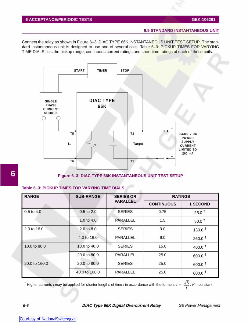
Connect the relay as shown in Figure 6–3: DIAC TYPE 66K INSTANTANEOUS UNIT TEST SETUP. The stan-dard instantaneous unit is designed to use one of several coils. Table 6–3: PICKUP TIMES FOR VARYINGTIME DIALS lists the pickup range, continuous current ratings and short time ratings of each of these coils.
Figure 6–3: DIAC TYPE 66K INSTANTANEOUS UNIT TEST SETUP
Table 6–3: PICKUP TIMES FOR VARYING TIME DIALS
RANGE SUB-RANGE SERIES OR PARALLEL
RATINGS
CONTINUOUS 1 SECOND
0.5 to 4.0 0.5 to 2.0 SERIES 0.75 25.0 †
1.0 to 4.0 PARALLEL 1.5 50.0 †
2.0 to 16.0 2.0 to 8.0 SERIES 3.0 130.0 †
4.0 to 16.0 PARALLEL 6.0 260.0 †
10.0 to 80.0 10.0 to 40.0 SERIES 15.0 400.0 †
20.0 to 80.0 PARALLEL 25.0 600.0 †
20.0 to 160.0 20.0 to 80.0 SERIES 25.0 600.0 †
40.0 to 160.0 PARALLEL 25.0 600.0 †
† Higher currents I may be applied for shorter lengths of time t in accordance with the formula: , K = constant
SINGLEPHASE
CURRENTSOURCE
TIMER
T3
T1
DIAC TYPE66K
TargetIin
T6
T5
START STOP
36/300 V DCPOWERSUPPLY
CURRENTLIMITED TO
200 mA
–
+
I Kt
--------=

GE Power Management DIAC Type 66K Digital Overcurrent Relay 6- 7
GEK-106261 6 ACCEPTANCE/PERIODIC TESTS
6
6.10 PERIODIC TESTS
It is recommended that the user perform a periodic test to verify that the relay is operating properly. It is recom-mended that a portion of the acceptance tests be performed to verify the relay. An inspection of the seal-in con-tacts can be performed by removing the relay from its case and visually inspecting the contacts for corrosion.
6.11 SERVICING
If the relay fails to perform as specified in this instruction manual consult the factory or call your local GE salesoffice. Before returning the relay consult with the GE Power Management technical support.
It is not recommended that the relay be serviced to the component level. This requires substantial investmentin repair/test equipment and in technical expertise, and usually results in a longer down time than if a sparerelay were used in its place, while the unit is shipped back to the factory.

6-8 DIAC Type 66K Digital Overcurrent Relay GE Power Management
6 ACCEPTANCE/PERIODIC TESTS GEK-106261
6
Figure 6–4: REAR, FRONT, AND TOP VIEWS OF THE DIAC TYPE 66K INTERIOR
GE Power Management DIAC Type 66K Digital Overcurrent Relay 6- 9
GEK-106261 6 ACCEPTANCE/PERIODIC TESTS
6
Figure 6–5: DIAC 66K FRONT AND REAR VIEWS

6-10 DIAC Type 66K Digital Overcurrent Relay GE Power Management
6 ACCEPTANCE/PERIODIC TESTS GEK-106261
6

GE Power Management DIAC Type 66K Digital Overcurrent Relay 7- 1
GEK-106621 7 SPECIFICATIONS
7
GEK-106621 7 SPECIFICATIONS 7.1 BURDENS
Burdens for the over-current units are listed in Table 7–1: BURDEN SETTINGS. Burdens decrease with in-creasing current above minimum setting, due to the power supply shunting in the power supply circuit. Sincethe power supply is the major portion of the burden, the burden for a given input current will be constant, irre-spective of pick-up settings on both TOC and IOC units.
Figure 7–1: BURDEN CURVE
BURDENS:0.1A / 0.5 A unit 0.45 VA
1.0A / 5.0 A unit 2.6 VA
Table 7–1: BURDEN SETTINGS
BURDEN at MINIMUM SETTING BURDEN IN Ω (Z) at MULTIPLES OF MINIMUM PICKUP
UNIT RANGE Hz R jX Z ∠ 3x 10x 20x 100x
1A 0.1 / 31.8 60 28.8 29.2 41.3 45° 9.36 2.32 1.24 0.768
5A 0.5 / 15.9 60 1.28 1.15 1.74 42° 0.394 0.094 0.052 0.034
4 55 6 7 8 1 2 3 4 55 6 7 10 2 3 4 55 6 1003
4
1
2
33
4
10
2
33
4
100
2
0.1 2 3 4 55 6 7 8 1 2 3 4 55 6 7 10 2
5AMP Model
1AMP Model
0.1 to 3.18 A (1 Amp Relays)
Current Range: 0.5 to 15.9 A (5 Amp Relays)
Burd
en
inV
A

7-2 DIAC Type 66K Digital Overcurrent Relay GE Power Management
7 SPECIFICATIONS GEK-106621
7
7.2 RATINGS
FREQUENCYSystem Frequency 50/60 Hz
CURRENT (1A OR 5A MODELS)
TRANSIENT OVERREACHMaximum Transient Overreach 7%
CONTACT RATINGS
7.3 ENVIRONMENTAL
AMBIENT TEMPERATUREStorage: –40 to +85°C
Operation: –25 to +70°C
Humidity: Up to 95% without condensing
INSULATION WITHSTAND TESTSImpulse Voltage: 5 KV peak, 1.2/50 µs, 0.5 Joules per
IEC255-5, Class III
SURGE WITHSTAND CAPABILITYFast Transient: Per ANSI C37.90.2-1989
Per IEC 60255-22-4
Oscillatory: Per ANSI C37.90.1-1989Per IEC 255-4
RADIO FREQUENCY WITHSTAND25 MHz to 1 GHz, keyed every 1 MHz for 2 seconds
Per ANSI C37.90.2
Per IEC 60255-22-3
ELECTROSTATIC DISCHARGEPer IEC 60255-22-2
NOTE: The DIAC Type 66K relay must be powered up at least once per year to avoid deterioration of electrolytic capacitors and subsequent relay failiure.
Table 7–2: MAXIMUM PERMISSIBLE CURRENT
1 A MODEL 5 A MODEL
Continuous 3 A 15 A
3 seconds 50 A 250 A
1 second 100 A 500 A
Table 7–3: OPERATING CURRENT RANGE
1 A MODEL 5 A MODEL
minimum 0.095 A 0.475 A
I2T (constant) 1520 38000
Table 7–4: MAXIMUM PERMISSIBLE CURRENT
Voltage Cont. Make & Carry 1
sec
Break Max. Load
DC resistive
125V250V
10A 30A 0.5 A0.3 A
60 W
DC inductive
L/R=40 ms
125V250V370V
10 A 30A 0.25 A0.15 A0.05 A
50 V

GE Power Management DIAC Type 66K Digital Overcurrent Relay A- 1
APPENDIX A A.1 CHANGE NOTES
AAPPENDIX A REVISIONSA.1 CHANGE NOTES A.1.1 REVISION HISTORY
A.1.2 ADDITIONS/CHANGES TO DIAC 66K MANUAL
Table A–1: REVISION HISTORY
MANUAL P/N DIAC 66K REVISION RELEASE DATE ECO
GEK-106261 --- --- ---
GEK-106261A --- --- ---
GEK-106261B SPDV130.A03 November 1, 1999 ---
GEK-106261C SPDV130.A03 November 16, 2000 DIAC66K-007
Table A–2: ADDITIONS/CHANGES TO DGP MANUAL GEK-106261C
PAGE INGEK-106261B
ADDITION/CHANGE(to GEK-106261C)
cover Updated GE contact information and manual part number. Moved warning concerning electrolytic capacitor deterioration to the SPECIFICATIONS chapter.
4-4 Updated Figure 4-2 to reflect the correct taps for 2 A and 0.2 A.
A-2 DIAC Type 66K Digital Overcurrent Relay GE Power Management
A.1 CHANGE NOTES APPENDIX A
A

GE Power Management DIAC Type 66K Digital Overcurrent Relay i
INDEX
Numerics
51 TOC CURVE ........................................................... 2-353 TOC CURVES ......................................................... 2-455 SHORT TIME TOC CURVES ................................... 2-557 MEDIUM TIME TOC CURVES.................................. 2-666 LONG TIME TOC CURVES...................................... 2-775 SHORT TIME TOC CURVES ................................... 2-877 TOC CURVES ......................................................... 2-995 SHORT TIME TOC CURVES ................................. 2-10
A
ACCEPTANCE TESTSdescription ................................................................ 6-1drawout relays ........................................................... 6-1instantaneous HDO unit ............................................. 6-5instantaneous unit test setup ..................................... 6-6pickup times for TOC alarm unit ................................. 6-3pickup times for TOC/ instantaneous HDO unit .... 6-5, 6-6visual inspection ........................................................ 6-1
ACCPETANCE TESTSinverse time .............................................................. 6-4
ADJUSTMENTSdigital units ............................................................... 4-1standard instantaneous unit ....................................... 4-1
APPLICATION ............................................................. 2-1
B
BLOCK DIAGRAM........................................................ 1-2BURDEN
curve ........................................................................ 7-1data .......................................................................... 4-2settings ..................................................................... 7-1specifications ............................................................ 7-1
C
CALCULATION OF SETTINGS ..................................... 3-1CASE .......................................................................... 4-1COVER INSTALLATION ............................................... 4-3CURRENT
maximum permissible ................................................ 7-2operating range ......................................................... 7-2
CURVESsee TOC curves
D
DEFINITE TIME ......................................................... 2-17DRAWOUT RELAYS
testing ....................................................................... 6-1
E
ENVIRONMENT ........................................................... 5-1ENVIRONMENTAL SPECIFICATIONS .......................... 7-2
EXTERNAL CONNNECTIONS FOR MOTOR PROTECTION5-4
F
FEATURES ................................................................. 1-1FRONT VIEW .............................................................. 1-1FRONT VIEW OF DIAC 66K ......................................... 6-9FUNCTIONAL BLOCK DIAGRAM ................................. 1-2
H
HANDLING .................................................................. 4-3HARDWARE DESCRIPTION ........................................ 4-1
I
I2T TIME CURVE ........................................................2-18IAC51 TOC CURVE ..................................................... 2-3IAC53 TOC CURVES ................................................... 2-4IAC77 TOC CURVES ................................................... 2-9IEC EXTREMELY INVERSE TOC CURVES .................2-13IEC INVERSE TOC CURVES ......................................2-11IEC VERY INVERSE TOC CURVES ............................2-12IEEE EXTREMELY INVERSE TOC CURVES ...............2-16IEEE INVERSE TOC CURVES ....................................2-14IEEE VERY INVERSE TOC CURVES ..........................2-15INDICATORS .............................................................. 4-2INSTALLATION ........................................................... 5-1INSTANTANEOUS HDO UNIT
testing ...................................................................... 6-5INTERIOR VIEWS OF DIAC 66K .................................. 6-8INTERNAL CONNECTIONS DIAGRAM ......................... 5-3INTERNAL/EXTERNAL CONNECTIONS ....................... 5-2INTRODUCTION .......................................................... 1-1INVERSE TIME TEST .................................................. 6-4IOC CURVE FOR HDO INSTANTANEOUS UNIT ..........2-19IOC CURVE FOR STANDARD (EM) INSTANTANEOUS
UNIT......................................................................2-20
M
MANUAL TRIP CIRCUIT TEST ..................................... 4-3MAXIMUM PERMISSIBLE CURRENT ........................... 7-2MECHANICAL INSPECTION ........................................ 6-1MOTOR PROTECTION CHARACTERISTIC CURVE ...... 5-6MOUNTING ................................................................. 5-1
O
OPERATING COIL TAPPING ....................................... 4-4OPERATING CURRENT RANGE .................................. 7-2ORDER CODES .......................................................... 1-2ORDERING ................................................................. 1-2
P
PANEL MOUNTING AND DRILLING ............................. 5-5

ii DIAC Type 66K Digital Overcurrent Relay GE Power Management
INDEX
PERIODIC TESTS .................................................6-1, 6-7POINTER STYLES....................................................... 4-1PRODUCT DESCRIPTION ........................................... 2-1
R
RATINGS ..............................................................2-2, 7-2RATINGS OF TARGET AND SEAL-IN COIL .................. 2-2REAR VIEW OF DIAC 66K ........................................... 6-9RECEIVING ................................................................. 4-3RESET TARGETS ....................................................... 4-3REVISION HISTORY ................................................... A-1
S
SELECTION GUIDE ..................................................... 1-2SERVICING ................................................................. 6-7SETTING RANGE ........................................................ 2-1SPECIFICATIONS ....................................................... 7-1STANDARD (EM) INSTANTANEOUS UNIT ..................2-19STORAGE ................................................................... 4-3SURGE GROUND ........................................................ 5-1
T
TARGET AND SEAL-IN UNIT ....................................... 4-3TARGETS ................................................................... 4-2
TESTSsee ACCEPTANCE TESTS and PERIODIC TESTS
TIME OVERCURRENT CURVESsee TOC CURVES
TOC / INSTANTANEOUS HDO UNIT – DEFINITE TIME .6-4TOC / INSTANTANEOUS HDO UNIT – INVERSE TIME ..6-3TOC ALARM UNIT ........................................................6-2TOC CURVES
55 short time ..............................................................2-557 medium time ..........................................................2-666 long time ...............................................................2-775 short time ..............................................................2-895 short time ............................................................2-10IAC51 ........................................................................2-3IAC53 ........................................................................2-4IAC77 ........................................................................2-9IEC extremely inverse ..............................................2-13IEC inverse ..............................................................2-11IEC very inverse .......................................................2-12IEEE extremely inverse ............................................2-16IEEE inverse ............................................................2-14IEEE very inverse .....................................................2-15
TOC FUNCTIONS .........................................................2-2TRIP CIRCUIT ..............................................................4-3
V
VISUAL INSPECTION ...................................................6-1
GE Power Management DIAC Type 66K Digital Overcurrent Relay
NOTES

DIAC Type 66K Digital Overcurrent Relay GE Power Management
GE POWER MANAGEMENT WEBSITE
The latest product information for the DIAC 66K relay is available on the Internet via the GE Power Manage-ment home page:
JVVRYYY)'KPFWUVTKCNEQORO
This site provides access to the following customer services:
• Digital Products DirectoryA brief description of products can be viewed online.
• Product CatalogIndividual product brochures can be downloaded and printed
• Product Selector GuideA graphical tool for finding the product you are inter-ested in
• Sales OfficesA complete listing of world-wide sales offices
• Technical SupportComplete contact information is available
• Instruction ManualsManuals for many products are now available online
• GE Product SoftwareThe latest working versions of product software
• Technical DrawingsMany technical drawings are available in either AutoCAD, CorelDRAW, or PDF formats.
• Order CodesOrder codes for many products can be downloaded and printed
• Technical PublicationsPapers related to power management
Much more is also available. Visit us online at www.GEindustrial.com/pm.

GE Power Management DIAC Type 66K Digital Overcurrent Relay
NOTES