di-acro no. 6 & no. 8 power bender instruction manual · pdf file ·...
TRANSCRIPT

DI-ACRO
NO. 6 & NO. 8 POWER BENDER
INSTRUCTION MANUAL
Toll Free: (855) 651-8948 - www.diacro.com - Fax: (651) 342-1293
12430 55th St. No. - Oak Park Heights, MN 55082 - USA
REV. B 12/16 2
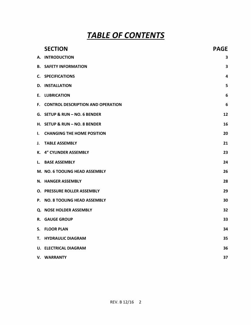
TABLE OF CONTENTS
SECTION PAGE A. INTRODUCTION 3
B. SAFETY INFORMATION 3
C. SPECIFICATIONS 4
D. INSTALLATION 5
E. LUBRICATION 6
F. CONTROL DESCRIPTION AND OPERATION 6
G. SETUP & RUN – NO. 6 BENDER 12
H. SETUP & RUN – NO. 8 BENDER 16
I. CHANGING THE HOME POSITION 20
J. TABLE ASSEMBLY 21
K. 4” CYLINDER ASSEMBLY 23
L. BASE ASSEMBLY 24
M. NO. 6 TOOLING HEAD ASSEMBLY 26
N. HANGER ASSEMBLY 28
O. PRESSURE ROLLER ASSEMBLY 29
P. NO. 8 TOOLING HEAD ASSEMBLY 30
Q. NOSE HOLDER ASSEMBLY 32
R. GAUGE GROUP 33
S. FLOOR PLAN 34
T. HYDRAULIC DIAGRAM 35
U. ELECTRICAL DIAGRAM 36
V. WARRANTY 37
REV. B 12/16 3
A. Introduction
This instruction manual serves two purposes:
1. It outlines essential information for installation, operation, and maintenance of the PLC
controlled No. 6 and No. 8 Power Bender.
2. It gives a complete parts breakdown identified by number, should replacements be
required.
It is recommended that the operator become familiar with the bender’s instructions and
operating details. It is also recommended that the foreman or supervisor familiarize himself with
the operating details of the machine to insure its continued efficient service.
The Di-Acro Power Benders are designed to accommodate two different types of tooling.
The No. 6 Bender is designed to handle tubing to 1.125” diameter (.060” wall-mild steel) and
mild steel round bars up to .563” diameter.
The No. 8 Bender will handle mild steel round bar up to 1” diameter and tubing to 1.500”
diameter (.060” wall-mild steel)
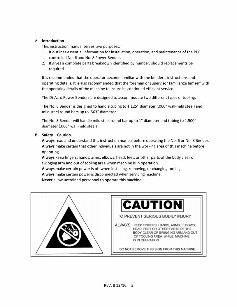
B. Safety – Caution
Always read and understand this instruction manual before operating the No. 6 or No. 8 Bender.
Always make certain that other individuals are not in the working area of this machine before
operating.
Always keep fingers, hands, arms, elbows, head, feet, or other parts of the body clear of
swinging arm and out of tooling area when machine is in operation.
Always make certain power is off when installing, removing, or changing tooling.
Always make certain power is disconnected when servicing machine.
Never allow untrained personnel to operate this machine.

REV. B 12/16 4
C. Specifications
NO. 6 TOOLING HEAD NO. 8 TOOLING HEAD
CAPACITY (MATERIAL)*
1-1/4” OD TUBE - .060” WALL
1-1/2” OD TUBE - .060” WALL
¾” I.P.S. 1” I.P.S.
5/8” DIA SOLID ROUND 1” DIA SOLID ROUND
½” SOLID SQUARE 7/8” SOLID SQUARE
¼” X 2” FLAT (EASY WAY) 3/8” X 4” FLAT (EASY WAY)
¼” X 1” FLAT (HARD WAY) 3/8” X 1” FLAT (HARD WAY)
MAXIMUM RADIUS 9” 24”
HYDRAULIC PRESSURE 1250 PSI 1250 PSI
MOTOR 3 HP 3 HP
CYLINDER BORE 4” 4”
FLOOR SPACE 18” X 62” 18” X 62”
SHIPPING WEIGHT 1,150 LBS 1,150 LBS
SPINDLE TORQUE 3487 FT*LBS 3487 FT*LBS
VOLTAGE REQUIREMENTS 208, 230, OR 460 VAC, 3 PH, 60HZ
*ALL MATERIAL (EXCEPT I.P.S.) IS SPECIFIED AS MILD STEEL (57 KSI YIELD STRENGTH) OR EQUIVALENT.

REV. B 12/16 5
D. Installation
During shipment, the bender may have accumulated a coating of dust or grit. Remove all dirt
and rust preventative with cleaning solvent.
WARNING: To prevent serious bodily injury fasten machine to floor through four holes (5/8”
diameter) provided in the base of the machine.
When shipped, the gauge is removed for packing purposes. Install one of the two gauge groups
as shown below if desired.
Note: The Stop Rod Weldment is inserted through the table assembly from the Operator’s
Console side of the table. The appropriate Gauge Group is then installed onto this weldment
from the opposite side. The “pin” through the Stop Rod Weldment will engage a slot in the hole
of the knurled knob to allow the knob assembly to rotate the Gauge Group.
Note: Install gauge group “A” for short or single length bends. Install group “B” for longer or
multiple length bends.
Note: It is suggested that all four stop arms be placed at right angles to each other even if only
one or two are needed so that the knurled knob can be easily turned to position the stops. IF the

REV. B 12/16 6
stop arms are not located as above, the group will be out of balance and may cause binding of
the knurled knob.
Connect electricity to a three-phase input supply making certain that the transformer and motor
are connected properly for power being supplied. (208-230, or 460 VAC).
Check pump rotation. Power up the machine. Start the hydraulics by rotating the emergency
stop button clockwise, pressing the power on/reset button, and pressing the green start button
on the operator console. Open the door in the base and make sure that the pressure gauge
indicates a value around 1250 psi. If no pressure is indicated by the gauge, the motor is spinning
the wrong direction. Stop the pump by pressing the red stop button on the operator’s console
and disconnect power. Swap two of the input power leads at the machine disconnect to change
the motor direction.
Check the oil level in the sight glass on the tank in the base of the machine. If oil is required, use
the oil detailed in the lubrication section of this manual.
E. Lubrication
If the oil level is low in the sight glass on the side of the hydraulic tank, fill with Shell Tellus S2 M
32 or equivalent. Under no circumstances is a detergent motor oil to be used.
Lubricate the Grease Fitting (No. 29 in the Table Assembly parts breakdown) on the Cam
Follower (No. 29) every 500 hours or every 3 months. Use NLGI No 2 grease to lubricate this
component.
Bare metal surfaces on the tooling and slides can be lubricated with Boeshield T-9, or an
equivalent thin-film lubrication to prevent corrosion in high moisture environments. This can be
applied as needed.
F. Control Description and Operation
1. Initial Power Up
After providing the proper power source to the main electrical enclosure, rotate
the disconnect switch to the “on” position. This will provide power to the PLC
and control panel.
Rotate the Emergency Stop button on the control panel clockwise to deactivate.
Press the “Power on/Reset” button.
Press the “Start” button to start the hydraulic system. The “Stop” button will
shut down the hydraulic system. NOTE: Stop the pump if the machine will be
sitting for a long period. Allowing the pump to run idle can cause the hydraulic
oil to heat up and require replacement.
REV. B 12/16 7
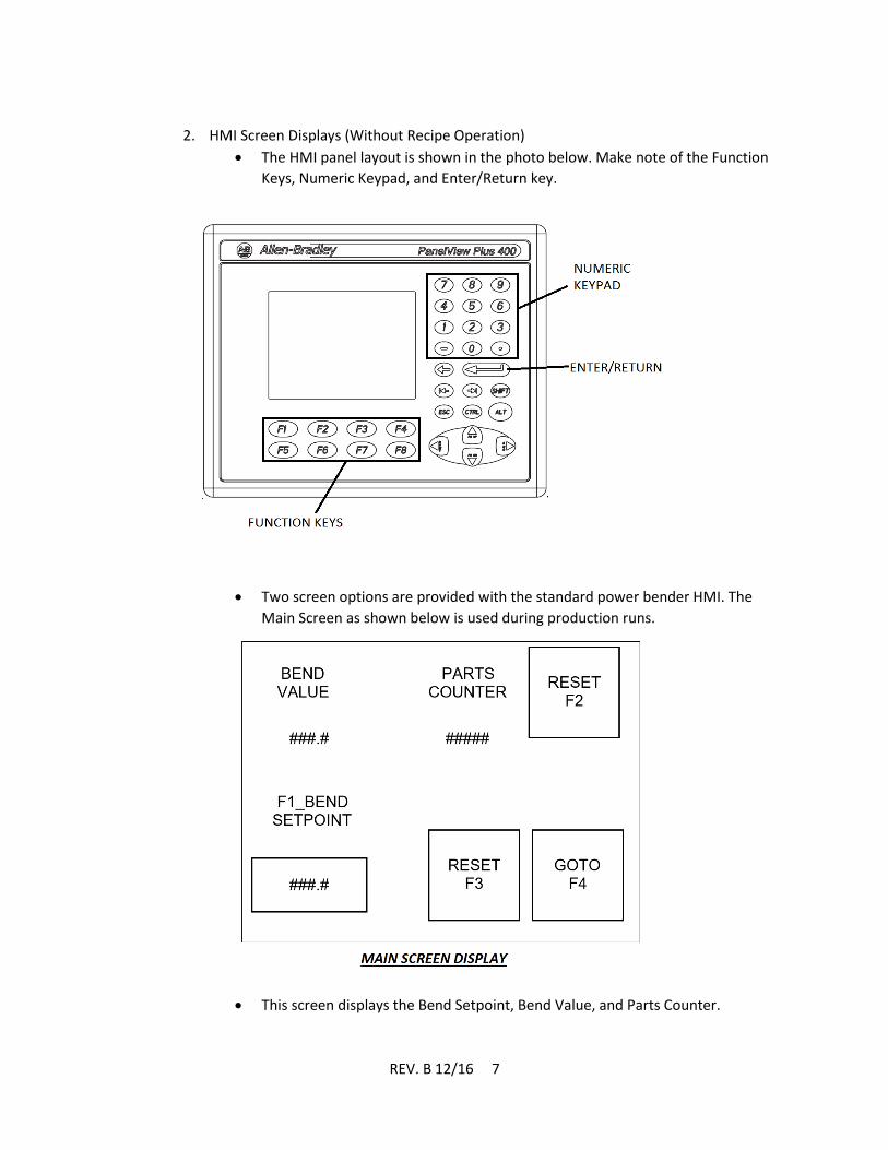
2. HMI Screen Displays (Without Recipe Operation)
The HMI panel layout is shown in the photo below. Make note of the Function
Keys, Numeric Keypad, and Enter/Return key.
Two screen options are provided with the standard power bender HMI. The
Main Screen as shown below is used during production runs.
This screen displays the Bend Setpoint, Bend Value, and Parts Counter.

REV. B 12/16 8
The “Manual/Homing” Screen is used to run the machine manually and to home
the machine. This screen is shown below.
This screen displays the Bend Value, and indicates whether the machine is
Homing or Homed during the Homing procedure.
On either screen, the Function Keys are used to perform whatever functions are
displayed on the screen at the time, or toggle between different modes as
displayed. This is covered in detail in the Homing, Manual, and Automatic
Operation sections that follow.
3. Manual Operation
CAUTION: When operating the power bender in manual mode, it is possible to crash
the tooling setup more readily than when it is set up in automatic mode. Make sure
you are familiar with all the controls and the direction of travel prior to actuating the
machine.
When the machine is initially powered up, the Main Screen will be displayed.
Press F4 to advance to the Manual/Homing Screen display.
The Manual/Homing screen shows the Bend Value, Mode (Automatic or
Manual), direction of travel (Extend or Retract), and Homing/Home State.
The Function Keys will toggle the values shown above each function key
descriptor in each box (F1, F2, etc.)
The value displayed above F1 is what mode the bender is in. Use the F1 button
to toggle between Auto and Manual
The value displayed above F2 displays the direction of travel that the bender will
move when it is actuated. Extend moves the tooling head counter-clockwise
when viewed from above, and Retract moves the tooling head clockwise. Extend
will also increase the bend value displayed, while Retract decreases the bend
value.
Note that neither the Home Position Proximity Switch nor the Bend Setpoint will
stop the bender when in Manual Mode.

REV. B 12/16 9
Once the desired bend has been set up, place your fingers in the two-hand
safety switches located on either side of the Operator’s Console. Note that the
machine will begin moving when your fingers enter these switches. It will not
stop until your fingers are removed or the machine runs out of travel.
When the desired travel has been reached, take your fingers off the safety
switches. Press F2 to reverse the travel if desired. Actuate the safety switches to
move the bender back to the point you started.
4. Homing the Bender
When the machine is initially powered up, the Main Screen will be displayed.
Press F4 to advance to the Manual/Homing Screen display.
Once in the Manual/Homing Screen, note that the Homing and Homed indicator
circles are initially unfilled. This is normal, and should be the case regardless of
the Bend Value. This is because any time that the hydraulic system is powered
down, the PLC unlatches the home position.
Ensure that the Bend Value displayed is a positive number or zero. If the Bend
Value displayed is a negative number, refer to the Manual Operation section
and extend the bender until the Bend Value is zero or positive.
Press F1 until Auto is displayed in the box above F1.
Press F2 to put the machine in Retract Mode if it is in Extend Mode.
Press F3 to begin the Homing Sequence. If the Bend Value is 0.0, the indicator
circle next to Homing will briefly flash, then the circle next to Homed will be
filled. If the Bend Value is not 0.0, the indicator circle next to Homing will be
filled.
Actuate the machine by putting your fingers into the safety switches on the
sides of the operator console. The bender will then retract to 0.0, and the
indicator circles will show that the machine has been homed.
NOTE: The machine will only retract during the Homing sequence. If you happen to
begin this sequence from a negative Bend Value, and cannot move the machine in
Manual Mode, you will need to shut off the hydraulic system. You may then restart
the hydraulics and extend the machine in Manual Mode until the Bend Value is
positive prior to attempting to home the machine.
5. Automatic Operation
NOTE: The machine will not operate in Automatic Mode without being homed. Follow
the procedure outlined above for Homing the Bender to home the machine prior to
Automatic Operation.
NOTE: Most ductile materials will exhibit some spring back when bending. Parts can be
overbent to compensate for spring back. Spring back is determined by material type,
part geometry, and even grain direction. Because of this, you will need to determine the
amount of overbending required experimentally in manual mode. This will allow you to
determine the exact bend set point for your specific application.
The Automatic Mode of operation allows the operator to set a desired bend set
point for the machine to repeat. To set up this mode of operation from the
REV. B 12/16 10
Manual/Homing Screen, press F4 (Return). This will toggle the HMI display back
to the Main Screen.
In the Main Screen, press F1 to enter the Bend Set Point. The Bend Set Point
value should be highlighted on the HMI. Use the numeric keypad to enter the
desired Bend Set Point. Save the Bend Set Point by pressing Enter/Return.
Press F1 to exit the Bend Set Point mode.
If desired, the production counter can be reset in this screen by pressing F2.
Activate the bender by actuating the two-hand safety switches on the sides of
the operator console. The bender will then extend until the safety switches are
not actuated or the bend set point is reached, whichever comes first.
Once the bend set point is reached, remove your hands from the switches.
To retract the machine, return your hands to the safety switches. The Bender
will automatically change directions and retract home so long as the switches
are actuated.
NOTE: During Automatic Operation, the bender extends to the Bend Set Point. Once
it reaches the set point, the PLC switches to Homing mode internally, and will re-
home upon retraction. The machine is coded this way to combat any drift
introduced by delays in the mechanical or hydraulic system.
6. Recipe Operation (If Installed)
The optional Recipe Operation function allows the user to save recipes of up to
4 consecutive bends in a recipe that may be recalled when needed for
production. Up to 75 unique recipes can be saved in the internal memory.
HMI Screen Displays
The Manual/Homing Screen Display is unchanged from the screen shown
above. Homing and manual operation is also the same as listed above.
The Main Screen is shown below.

REV. B 12/16 11
For Automatic operation with the recipe option, a recipe must be
programmed and selected. Press F1 to advance to the recipe screen.
The Recipe Setup Screen Display is shown below.
When this screen is displayed, recipes can be programmed and selected.
Press F1 to bring up the recipe selection popup. Use the numeric keypad
to enter the desired recipe (1 to 75 are available for use), and press
Enter/Return to close the popup. The recipe number should be
displayed in the box under Recipe Number on the display.
To Program bends, press the function key (F5-F8) for the corresponding
bend value to program that value. When one of these function keys is

REV. B 12/16 12
pressed, a popup will be displayed to enter the value. Use the numeric
keypad to enter the desired value. Press Return/Enter to save this value.
If less than four bends are desired, leave the bends that are not desired
set to zero.
Once the desired bend angles have been programmed, press F3 to save
the recipe.
Press F4 to return to the Main Screen. Production runs are performed
from this screen.
Recipe operation is similar to Automatic Operation. When the bender is
activated, it will advance to the first bend set point, or until the safety
switches are released. Once the bend set point has been reached, the
bender will stop until the safety switches are released, then retract once
the safety switches are re-actuated.
After the first bend, re-set the part and tooling to perform bend two, if a
second bend is desired. The bender will automatically advance to the
next programmed bend, if bend two has a nonzero value programmed.
Repeat this step for all of the programmed bends.
Once the bender has performed the last non-zero bend in the program,
the production counter will increase by one and the bend value will
display the programmed bend angle for bend one.
G. No. 6 Bender Set-up and Run
1. Turn power on. Make sure rack assembly is fully retracted into the cylinder. If you
ordered the machine complete with the No. 6 tooling assembly, the machine was
set up at the factory for this position to be aligned properly for this tooling
assembly.
2. Turn power off. Set Rotating arm on top of the Table per the diagram below.
3. Place the slide onto the table adjacent to the rotating arm as shown. Insert the 3/8”
socket head cap screws into the slide and loosely thread into the table top.
4. Insert the three ½” dowel pins (provided) into the ½” holes in the slide and tap
down until they are flush with the top of the slide. Tighten the cap screws in the
slide at this time.
REV. B 12/16 13
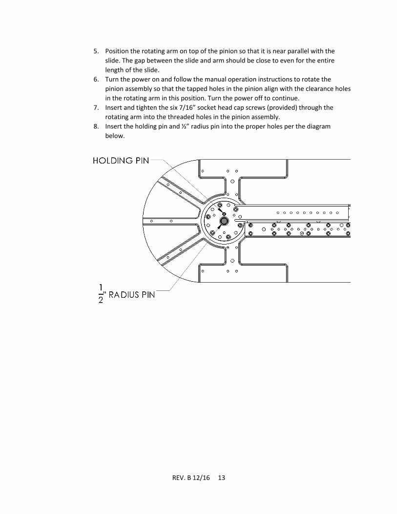
5. Position the rotating arm on top of the pinion so that it is near parallel with the
slide. The gap between the slide and arm should be close to even for the entire
length of the slide.
6. Turn the power on and follow the manual operation instructions to rotate the
pinion assembly so that the tapped holes in the pinion align with the clearance holes
in the rotating arm in this position. Turn the power off to continue.
7. Insert and tighten the six 7/16” socket head cap screws (provided) through the
rotating arm into the threaded holes in the pinion assembly.
8. Insert the holding pin and ½” radius pin into the proper holes per the diagram
below.
REV. B 12/16 14
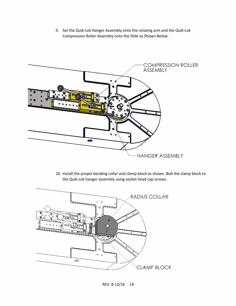
9. Set the Quik-Lok Hanger Assembly onto the rotating arm and the Quik-Lok
Compression Roller Assembly onto the Slide as Shown Below.
10. Install the proper bending collar and clamp block as shown. Bolt the clamp block to
the Quik-Lok hanger assembly using socket head cap screws.

REV. B 12/16 15
11. Adjust the Quik-Lok hanger that controls the clamp block.
a. Advance the Quik-Lok hanger handle toward the radius collar so that it is in
the position closest to the radius collar.
b. Slide the hanger forward so that the clamp block touches the radius collar.
c. Insert spacer rods in between the hanger and knurl head screw to hold the
hanger in this position, shown below. Spacer rods should be removed or
added depending on the bend radius. Some experimentation may be
needed to determine the proper number and type of spacer rods used.
d. Insert and tighten bolts to bolt the hanger down to the rotating arm.
e. Pull the handle back and insert a piece of desired bend material in between
the clamp block and radius collar. Move the handle forward to make sure
that the material is clamped tightly into place. If adjustment is needed,
loosen the hanger bolt and make fine adjustments via the knurl head screw.
The Quik-Lok should lock into place when the material to be bent is clamped
tightly.
12. Adjust the Compression Roller Assembly per above, using the proper follow bar in
lieu of the clamp block. It may be easier to have material clamped in place to bend
during this adjustment since the follow bar does not bolt to the compression rollers.
13. Power up the machine and perform test bends in Manual mode until the desired
bend is achieved. Once the desired bend has been determined, use the Bend Value
number to program the machine in Automatic Mode to duplicate this bend. Please
reference the Operation section of this manual for instructions on the operation of
manual and automatic modes.

REV. B 12/16 16
NOTE: The No. 6 Bender tooling and PLC is designed to run in the counter-clockwise direction. However,
it is possible to set up the machine to perform clockwise bends. If you have a need to run the bender in
this manner, please contact Di-Acro for further instruction.
H. No. 8 Bender Set-up and Run
NOTE: This procedure details the setup of this tooling for bending in the counter-clockwise
direction. The tooling and PLC package is designed to run in this direction. If clockwise bending is
desired, please contact Di-Acro for assistance.
1. When you receive your machine, verify that all parts for this tooling head have been
included. Refer to the parts breakdown on pages 20 and 21 for a list of these components.
2. Turn power on. Make sure that the rack assembly is retracted fully into the cylinder by
retracting the machine until it stops in manual mode. See the operation section of this
manual for instructions on operating the machine.
3. Place Mounting Plate and Nose Holder Slide into position on top of the machine as shown
below. The Mounting plate is centered on the Pinion Assembly by a small Spacer located on
top of the pinion. The Nose Holder Slide should be lined up with the holes in the table.
4. Locate 3/8-16NC x 1-1/2” socket head cap screws (20), and loosely thread them into the
table through the holes in the nose holder slide.
5. Insert the five ½” DIA x 1-3/4” long dowel pins through the slide into the table through the
slide. Tap them down so that they are flush with the top of the slide. Tighten the socket
head cap screws.

REV. B 12/16 17
6. Place the nose holder assembly on the slide as shown. Do not bolt down at this time.
7. Insert desired radius pin into center hole on mounting plate. If a radius collar is desired,
insert a ½” radius pin into this hole, then slip the radius collar over it.
8. To complete setup, you will need a piece of the desired bend material to properly locate the
locking pin and forming nose assembly. Place the material against the radius collar in the
desired bend orientation. Locate the hole in the mounting plate that allows a locking pin,
when rotated counter-clockwise, to lock tightly against the material, holding it against the
radius collar. An example of this is shown below.
REV. B 12/16 18
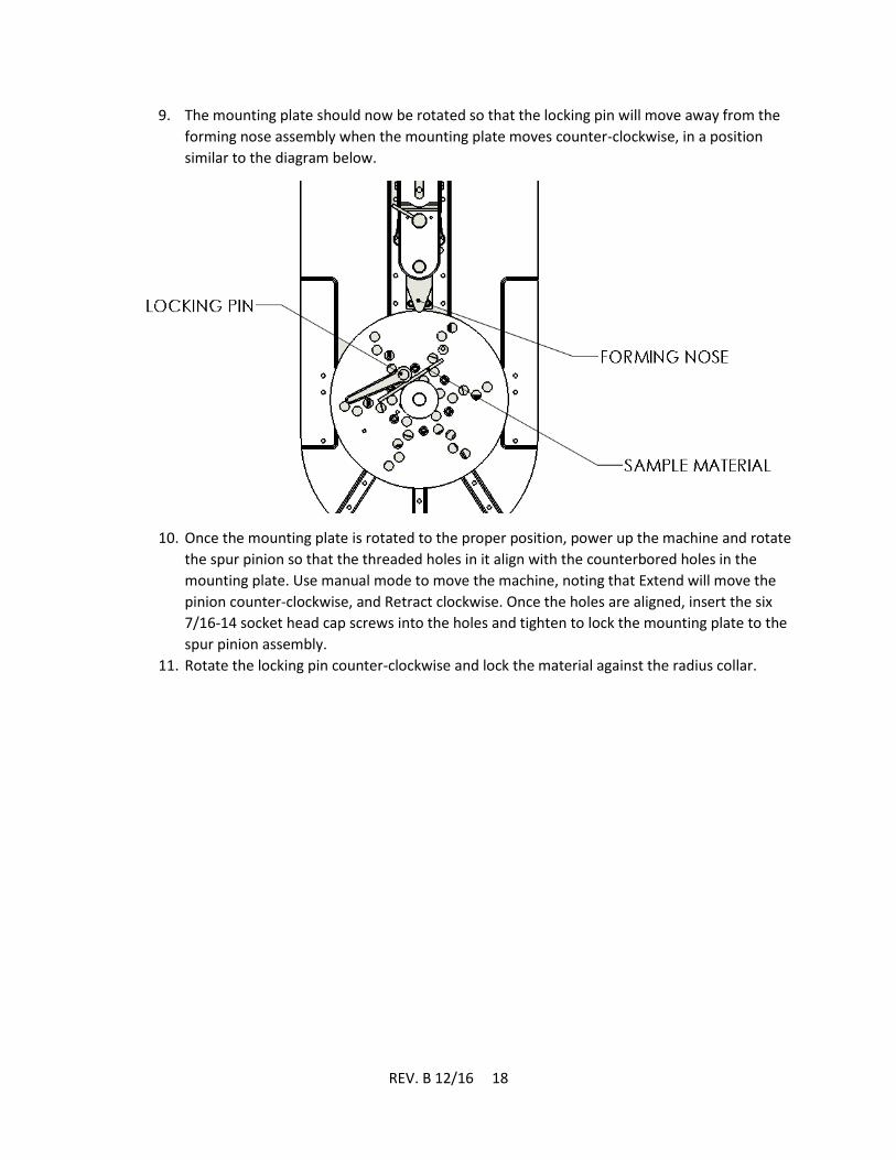
9. The mounting plate should now be rotated so that the locking pin will move away from the
forming nose assembly when the mounting plate moves counter-clockwise, in a position
similar to the diagram below.
10. Once the mounting plate is rotated to the proper position, power up the machine and rotate
the spur pinion so that the threaded holes in it align with the counterbored holes in the
mounting plate. Use manual mode to move the machine, noting that Extend will move the
pinion counter-clockwise, and Retract clockwise. Once the holes are aligned, insert the six
7/16-14 socket head cap screws into the holes and tighten to lock the mounting plate to the
spur pinion assembly.
11. Rotate the locking pin counter-clockwise and lock the material against the radius collar.

REV. B 12/16 19
12. Adjust the nose holder assembly.
a. Push the nose holder assembly so that the nose holder touches the sample material,
as shown below.
b. Place the Nose Holder Support onto the Slide behind the Nose Holder Assembly so
that the Nose Holder Support Screw is facing the Nose Holder Assembly. Align the
bolt holes with threaded holes in the slide so that the support screw can be
extended to push the nose holder assembly toward the work piece.
c. Tighten bolts “B” securely.
d. Finger tighten bolts “A”
e. Adjust Nose Holder Support Screw “C” until nose comes in contact with work piece.
f. Tighten bolts “A” securely.
13. Follow Manual Operation instructions to test bend a part.

REV. B 12/16 20
I. Changing the Home Position.
On some setups, it may be necessary to change the home position of the bender. This is simple
to do if you follow the procedure below:
1. Without tooling on the tooling head setup, retract the bender all the
way in Manual mode.
2. Place the tooling, locking pin, and test material onto the tooling head.
3. If the tooling is 60 degrees or more out of alignment with the forming
nose, rotate the tooling head to get closer to the proper alignment.
4. Extend the bender in manual mode until the tooling is aligned with the
forming nose.
5. Loosen the clamping screw that clamps the trip clamp to the bottom of
the spur pinion assembly under the table. Rotate the trip clamp on the
pinion assembly so that the trip arm illuminates the LEDs on the
proximity switch.
6. Tighten the socket head cap screw to lock the assembly in this position.
7. Home the machine per the instructions in the Operation section of this
manual (page 9).

REV. B 12/16 21
J. Table Assembly
REV. B 12/16 22
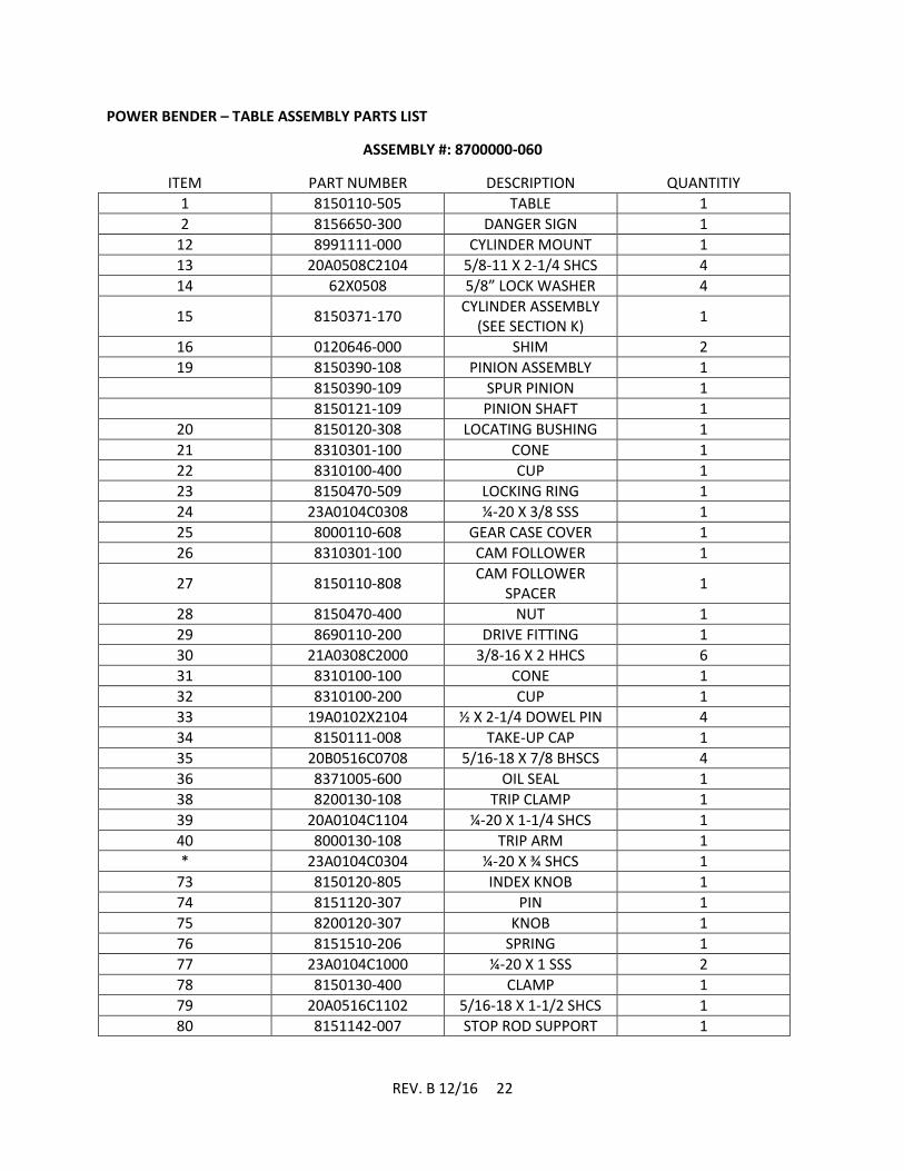
POWER BENDER – TABLE ASSEMBLY PARTS LIST
ASSEMBLY #: 8700000-060
ITEM PART NUMBER DESCRIPTION QUANTITIY
1 8150110-505 TABLE 1
2 8156650-300 DANGER SIGN 1
12 8991111-000 CYLINDER MOUNT 1
13 20A0508C2104 5/8-11 X 2-1/4 SHCS 4
14 62X0508 5/8” LOCK WASHER 4
15 8150371-170 CYLINDER ASSEMBLY
(SEE SECTION K) 1
16 0120646-000 SHIM 2
19 8150390-108 PINION ASSEMBLY 1
8150390-109 SPUR PINION 1
8150121-109 PINION SHAFT 1
20 8150120-308 LOCATING BUSHING 1
21 8310301-100 CONE 1
22 8310100-400 CUP 1
23 8150470-509 LOCKING RING 1
24 23A0104C0308 ¼-20 X 3/8 SSS 1
25 8000110-608 GEAR CASE COVER 1
26 8310301-100 CAM FOLLOWER 1
27 8150110-808 CAM FOLLOWER
SPACER 1
28 8150470-400 NUT 1
29 8690110-200 DRIVE FITTING 1
30 21A0308C2000 3/8-16 X 2 HHCS 6
31 8310100-100 CONE 1
32 8310100-200 CUP 1
33 19A0102X2104 ½ X 2-1/4 DOWEL PIN 4
34 8150111-008 TAKE-UP CAP 1
35 20B0516C0708 5/16-18 X 7/8 BHSCS 4
36 8371005-600 OIL SEAL 1
38 8200130-108 TRIP CLAMP 1
39 20A0104C1104 ¼-20 X 1-1/4 SHCS 1
40 8000130-108 TRIP ARM 1
* 23A0104C0304 ¼-20 X ¾ SHCS 1
73 8150120-805 INDEX KNOB 1
74 8151120-307 PIN 1
75 8200120-307 KNOB 1
76 8151510-206 SPRING 1
77 23A0104C1000 ¼-20 X 1 SSS 2
78 8150130-400 CLAMP 1
79 20A0516C1102 5/16-18 X 1-1/2 SHCS 1
80 8151142-007 STOP ROD SUPPORT 1
REV. B 12/16 23
ITEM PART NUMBER DESCRIPTION QUANTITY
84 8300142-007 MATERIAL STOP ROD
SUPPORT 2
85 23A0516C0104 5/16-18 X ¼ SSS 4
89 62X0308 3/8 LOCK WASHER 6
90 62X0516 5/16 LOCK WASHER 4
92 8150110-800 SPACER 2
* 8150740-101 PROXIMITY SWITCH
MOUNT 1
* 8150740-102 ENCODER FLEX PLATE 1
* 8150740-103 ENCODER ADAPTER 1
* 23A0X10C0104 10-24 X ¼ SSS 2
* 23A0X10C0102 10-24 X ½ SSS 1
* 20A0X08C0304 8-32 X ¾ SHCS 6
* 31X0X08C 8-32 JAM NUT 6
* 61X0X10 #10 FLAT WASHER 10
* 62X0X10 #10 LOCK WASHER 6
* 62X0104 ¼ LOCK WASHER 4
* 21A0104C0708 ¼-20 X 7/8 HHCS 4
*PARTS SHOWN WITH (*) IN ITEM COLUMN ARE NOT SHOWN ON ASSEMBLY DRAWING
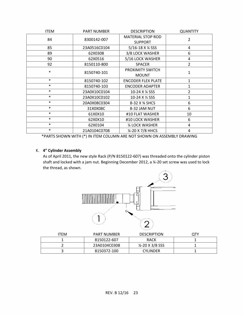
K. 4” Cylinder Assembly
As of April 2011, the new style Rack (P/N 8150122-607) was threaded onto the cylinder piston
shaft and locked with a jam nut. Beginning December 2012, a ¼-20 set screw was used to lock
the thread, as shown.
ITEM PART NUMBER DESCRIPTION QTY
1 8150122-607 RACK 1
2 23A0104C0308 ¼-20 X 3/8 SSS 1
3 8150372-100 CYLINDER 1
REV. B 12/16 24
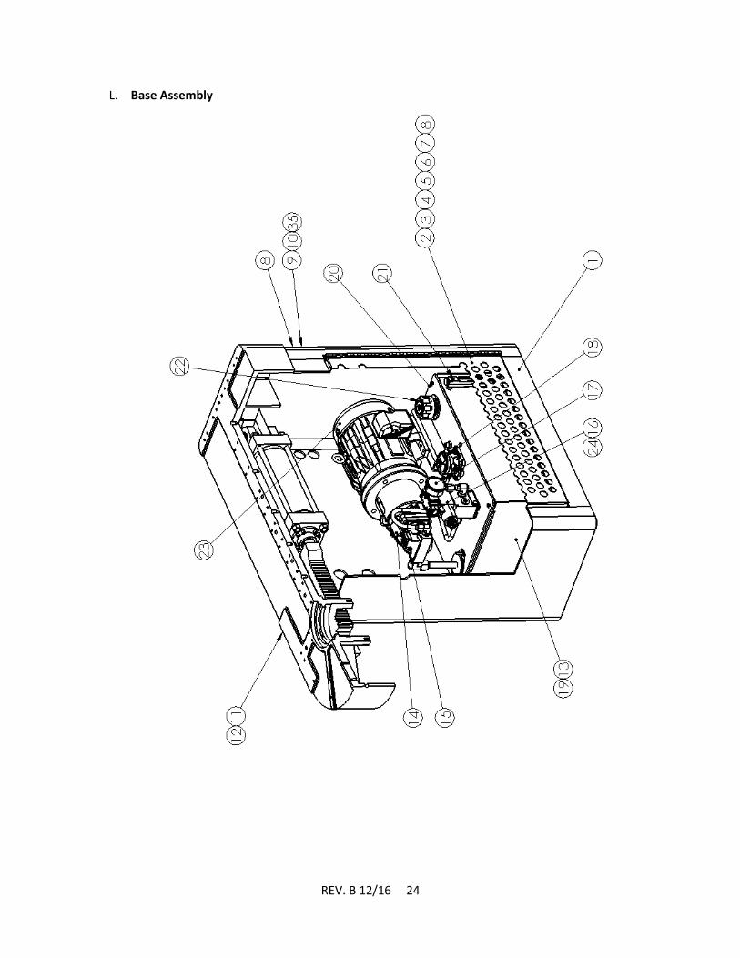
L. Base Assembly

REV. B 12/16 25
POWER BENDER – BASE ASSEMBLY PARTS LIST
ASSEMBLY # 121871-000
ITEM PART NUMBER DESCRIPTION QUANTITY
1 121871-100 BASE – SUB ASSEMBLY
1
2 121871-200 DOOR ASSEMBLY 1
3 8150720-108 DOOR 1
4 8150720-109 HINGE 1
5 8033343-000 LATCH 1
6 20A0104C0304 ¼-20 X ¾ SHCS 5
7 62X0104 ¼ LOCK WASHER 5
8 30X0104C ¼-20 FULL NUT 5
9 21A0308C0304 3/8-16 X ¾ HHCS 4
10 62X0308 3/8 LOCK WASHER 4
11 20A0102X1104 ½-13 X 1-1/4 SHCS 4
12 62X0102 ½ LOCK WASHER 4
13 1000307-000 HYDRAULIC POWER
SUPPLY 1
14 8150730-103 HYDRAULIC PUMP 1
15 8150730-104 PRESSURE
ADJUSTMENT 1
16 8150730-106 DIRECTIONAL VALVE 1
17 8150730-107 PRESSURE GAUGE 1
18 8150730-108 RETURN FILTER 1
19 8150730-109 RESERVOIR 1
20 8150730-110 DRAIN PLUG 1
21 8150730-111 SIGHT LEVEL/TEMP
GAUGE 1
22 8150730-112 FILLER / BREATHER
CAP 1
23 8150730-113 MOTOR 1
24 8150730-115 PO CHECK VALVE 1
25* 130-0221-P HYDRAULIC HOSE 8 FEET
26* 130-0213-P 90 DEG. MALE
ELBOW 2
27* 130-0214-P SWIVEL FITTING 4
28* 8150730-114 BUSHING 2
29* 20A0102C1304 ½-13 X 1-3/4 SHCS 4
30* 62X0102 ½ LOCK WASHER 4
31* 61X0102 ½ FLAT WASHER 4
32* 30X0102C ½-13 FULL NUT 4
33* 8150750-101 TAMPER PROOF LOCK 1
34* 100-0135-P NAMEPLATE 1
ITEMS MARKED WITH AN ASTERISK (*) ARE NOT SHOWN

REV. B 12/16 26
M. No. 6 Tooling Head Assembly

REV. B 12/16 27
NO. 6 TOOLING HEAD ASSEMBLY – PARTS LIST
ITEM PART NUMBER DESCRIPTION QUANTITY
1 20A0716C1104 7/16-14 X 1-1/4 SHCS 6
2 8156120-302 HOLDING PIN 1
3 8130016-970 RADIUS PIN 1
4 20A0516C0508 5/16-18 X 5/8 SHCS 2
5 8156111-371 HANGER ASSEMBLY 1
6 0308WILLIAMS
WASHER 3/8 WILLIAMS
WASHER 4
7 20A0308C2102 3/8-16 X 2-1/2 SHCS 4
8 8200111-371 ROTATING ARM
ASSEMBLY 1
9 8400111-301 SPACER ROD C – 4” 2
10 8300111-301 SPACER ROD B – 2” 2
11 8156111-301 SPACER ROD A – 1” 2
12 8700111-301 SCREW SUPPORT 2
13 20A0308C1102 3/8-16 X 1-1/2 SHCS 4
14 8500111-301 SCREW SUPPORT 2
15 20A0308C1102 3/8-16 X 1-1/2 SHCS 12
16 8910111-300 SLIDE 1
17 19A0102X1304 ½ X 1-3/4 DOWEL PIN 3
18 8000111-371 COMPRESSION
ROLLER ASSEMBLY 1

REV. B 12/16 28
N. Hanger Assembly
HANGER ASSEMBLY
PARTS LIST
ITEM PART NUMBER DESCRIPTION QUANTITY
1 8500111-300 HANDLE ROD 1
2 8120810-700 PLASTIC KNOB 1
4 19A0102X2102 ½ X 2-1/2 DOWEL PIN 1
5 19A0508X2102 5/8 X 2-1/2 DOWEL
PIN 1
6 1856111-302 HANGER WELDMENT 1
7 8920111-300 NOSE ASSEMBLY 1
7A 23A0104C0104 ¼-20 X ¼ SSS 1
8 8930111-300 LINK 2
9 8156120-301 LINK PIN 1
10 8400111-300 HANDLE BLOCK 1
10A 23A0104C0104 ¼-20 X ¼ SSS 2
REV. B 12/16 29
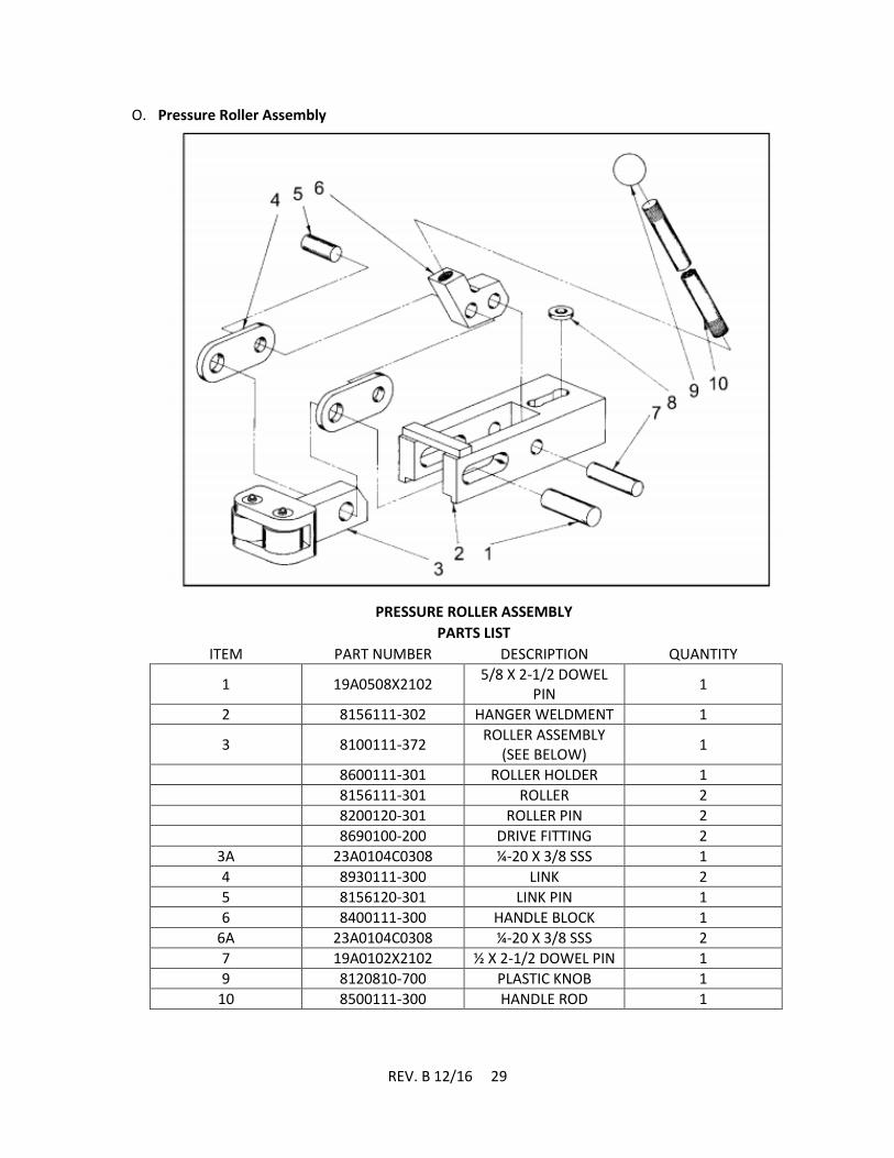
O. Pressure Roller Assembly
PRESSURE ROLLER ASSEMBLY
PARTS LIST
ITEM PART NUMBER DESCRIPTION QUANTITY
1 19A0508X2102 5/8 X 2-1/2 DOWEL
PIN 1
2 8156111-302 HANGER WELDMENT 1
3 8100111-372 ROLLER ASSEMBLY
(SEE BELOW) 1
8600111-301 ROLLER HOLDER 1
8156111-301 ROLLER 2
8200120-301 ROLLER PIN 2
8690100-200 DRIVE FITTING 2
3A 23A0104C0308 ¼-20 X 3/8 SSS 1
4 8930111-300 LINK 2
5 8156120-301 LINK PIN 1
6 8400111-300 HANDLE BLOCK 1
6A 23A0104C0308 ¼-20 X 3/8 SSS 2
7 19A0102X2102 ½ X 2-1/2 DOWEL PIN 1
9 8120810-700 PLASTIC KNOB 1
10 8500111-300 HANDLE ROD 1
REV. B 12/16 30
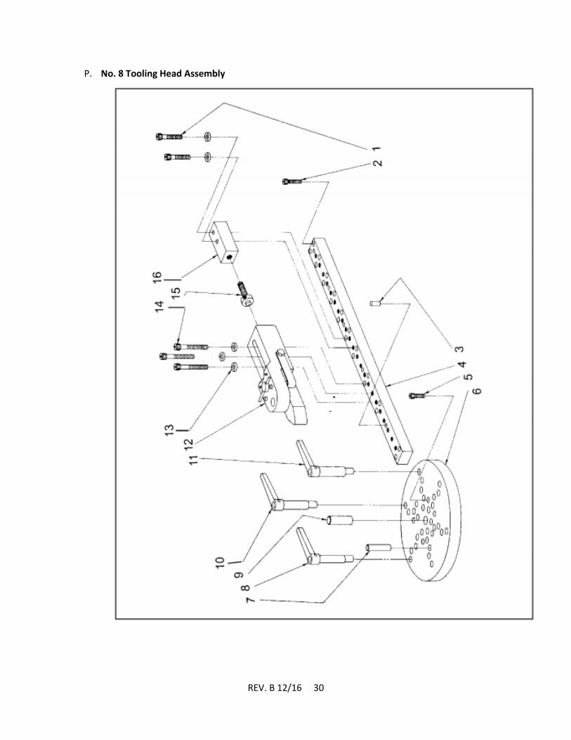
P. No. 8 Tooling Head Assembly

REV. B 12/16 31
NO. 8 TOOLING HEAD ASSEMBLY
PARTS LIST
ITEM PART NUMBER DESCRIPTION QUANTITY
1 20A0102C2102 ½-13 X 2-1/2 SHCS 2
2 20A0308C1102 3/8-16 X 1-1/2 SHCS 20
3 19A0308C1102 ½ X 1-3/4 DOWEL PIN 5
4 8158121-703 NOSE HOLDER SLIDE 1
5 20A0716C1104 7/16-14 X 1-1/4 SHCS 6
6 8158110-501 MOUNING PLATE 1
7 8158120-302 PIN 1
8 8158111-370 LOCKING PIN SMALL 1
9 8130016-970 RADIUS PIN 1
10 8000111-370 LOCKING PIN
MEDIUM 1
11 8100111-370 LOCKING PIN LARGE 1
12 8158121-771 NOSE HOLDER
ASSEMBLY 1
13 0102WILLIAMS
WASHER ½ WILLIAMS WASHER 5
14 20A0102C3102 ½-13 X 3-1/2 SHCS 3
15 8300121-701 NOSE HOLDER
SUPPORT SCREW 1
16 8158121-701 NOSE HOLDER
SUPPORT 1

REV. B 12/16 32
Q. Nose Holder Assembly
NOSE HOLDER ASSEMBLY
PARTS LIST
ITEM PART NUMBER DESCRIPTION QUANTITY
1 8210510-204 SPRING 1
2 8010461-000 STEEL BALL 1
3 8158121-702 TRIGGER 1
4 8500121-701 FORMING NOSE 1
5 23A0308X0102 3/8-16 X ½ SSS 1
6 8600121-701 NOSE HOLDER 1
7 8400121-701 NOSE PIN 1
9 8310301-200 NEEDLE ROLLER 2
10 18A0104X3000 ¼ X 3 SPRING PIN 1
11 8158510-401 NOSE SPRING 2
12 21A0516C0102 5/16-18 X ½ HHCS 2

REV. B 12/16 33
R. Gauge Group
GAUGE GROUP
PARTS LIST
ITEM PART NUMBER DESCRIPTION QUANTITY
1 8000142-007 STOP ARM 4
2 8151142-006 STOP ROD
WELDMENT 1
3 8200142-007 STOP BRACKET ARM 1
4 8100142-007 STOP BRACKET
ASSEMBLY 1
20A0516C1104 5/16-18 X 1-1/4 SHCS 6
20A0516C1000 5/16-18 X 1 SHCS 1
REV. B 12/16 34
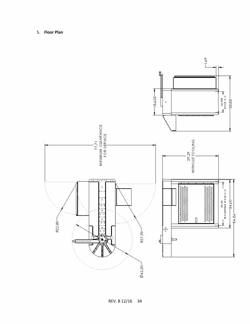
S. Floor Plan

REV. B 12/16 35
T. Hydraulic Diagram

REV. B 12/16 36
U. Electrical Diagrams
THIS PAGE INTENTIONALLY LEFT BLANK
Please reference the diagrams that were included with your bender.

REV. B 12/16 37
V. Warranty and Limitation of Liability
Defective parts, of a product manufactured by DI-ACRO, will be replaced or repaired at no
charge for twelve (12) months following delivery to the original purchaser. Labor is included for
the first 90 days. This warranty becomes void when products have not been used according to
instructions furnished by DI-ACRO, nor does it cover any altered parts of unauthorized repairs.
We cannot be responsible for the cost of repairs made of attempted outside of our factory. All
other warranty claims are made FOB our plant, providing such item(s) is returned freight
prepaid to our plant for examination.
This warranty does not apply to parts, components, or systems not manufactured by DI-ACRO.
These products are covered instead by the existing warranties, if any, of their manufacturers.
Normal service items with a reasonable life expectancy of less than one year are warranted only
to the extent of of the reasonable life under normal use and service.
Authorization must be obtained from DI-ACRO before returning parts or equipment to the
factory. DI_ACRO will satisfy this warranty by replacing the product or refunding the purchase
price upon receipt, inspection, and defect identification.
DI-ACRO’s liability under this warranty shall not exceed the amount paid for the product.
THIS IS DI-ACRO’S SOLE WARRANTY IN LIEU OF ALL OTHER WARRANTIES, EXPRESS OR
IMPLIED, WHICH ARE HEREBY EXCLUDED, INCLUDING IN PARTICULAR ALL WARRANTIES OF
MERCHANTABILITY, FITNESS, OR ANY LOSS, DAMAGE OR EXPENSES DIRECTLY OR INDIRECTLY
RELATED TO THE USE OF ITS PRODUCT OR FROM ANY OTHER CAUSE OR FOR CONSEQUENTIAL
DAMAGES INCLUDING, WITHOUT LIMITATION, LOSS OF TIME AND LOSS OF PRODUCTION.
IT IS EXPRESSLY UNDERSTOOD THAT DI-ACRO IS NOT RESPONSIBLE FOR DAMAGE OR INJURY
CAUSED TO OTHER PRODUCTS, MACHINERY, PROPERTY, OR PERSONS BY REASON OF THE USE
OF ITS PRODUCTS.
Toll Free: (855) 651-8948 – www.diacro.com - Fax: (651) 342-1293
12430 55th St No – Oak Park Heights, MN 55082 - USA