dg 415-1 army national guard design guide for … · november 1999 dg 415-1 draft dg 415-1 army...
TRANSCRIPT
November 1999 DG 415-1 DRAFT
DG 415-1 ARMY NATIONAL GUARD DESIGN GUIDE FOR READINESS CENTERS
NATIONAL GUARD
INSTALLATIONS DIVISION 111 SOUTH GEORGE MASON DRIVE
ARLINGTON, VA 22204-1382
NOVEMBER 1999
ARMY INSTALLATIONS THE FOUNDATION FOR READINESS

November 1999 DG 415-1
i
FOREWORD
This document was published by the National Guard Bureau, Army Installations Division (NGB-ARI). The guide is provided to assist States, possessions and design agencies in the design and preparation of the bidding/construction documents for United States Army National Guard (USARNG) Readiness Centers (previously called Armories) that qualify to be supported in part or totally from Federal funds. This guide is applicable to all projects for new construction including additions, alterations, rehabilitation and conversion of existing facilities. Distribution is limited. If additional copies are needed, local reproduction may be used. Users are encouraged to send comments and suggested improvements on DA Form 2028 (Recommended Changes to Publications/Blank Forms) directly to NGB-ARI, ARNG Readiness Center, 111 South George Mason Drive, Arlington, Virginia 22204-1382.
November 1999 DG 415-1
READINESS CENTERS
TABLE OF CONTENTS
Page
ii
CHAPTER 1 - GENERAL INFORMATION ........................... 1 C1.1. PURPOSE ............................................. 1 C1.2. ROLE OF FEDERAL GOVERNMENT .......................... 1 C1.3. FUNCTION AND OPERATION OF ARNG READINESS CENTERS .... 2 C1.4. PLANNING GUIDELINES ................................. 3 C1.5. CODES ............................................... 6 C1.6. POLICY .............................................. 7 CHAPTER 2 - ENGINEERING CRITERIA .......................... 9 C2.1. GENERAL ............................................. 9 C2.2. SITE WORK .......................................... 30 C2.3. CONCRETE ........................................... 49 C2.4. MASONRY ............................................ 50 C2.5. METALS ............................................. 52 C2.6. WOODS AND PLASTICS ................................. 53 C2.7. THERMAL AND MOISTURE PROTECTION .................... 53 C2.8. DOORS AND WINDOWS .................................. 55 C2.9. FINISHES ........................................... 57 C2.10. SPECIALTIES ....................................... 58 C2.11. EQUIPMENT ......................................... 60 C2.12. FURNISHINGS (NOT APPLICABLE) ..................... 60 C2.13. SPECIAL CONSTRUCTION .............................. 60 C2.14. CONVEYING SYSTEMS ................................. 61 C2.15. MECHANICAL ........................................ 61 C2.16. ELECTRICAL ........................................ 70 CHAPTER 3 - ENERGY CONSERVATION .......................... 82 C3.1. GENERAL ............................................ 82 C3.2. PASSIVE SOLAR ENERGY CONSERVATION .................. 82 C3.3. THE BUILDING ENVELOPE .............................. 85 C3.4. HVAC EQUIPMENT ..................................... 86 C3.5. DOMESTIC HOT WATER ................................. 87 C3.6. LIGHTING ........................................... 88

November 1999 DG 415-1
READINESS CENTERS
TABLE OF CONTENTS
Page
iii
CHAPTER 4 - ENVIRONMENTAL REQUIREMENTS ................... 89 C4.1. GENERAL ............................................ 89 C4.2. STORMWATER ......................................... 91 C4.3. UTILITIES .......................................... 91 C4.4. ASBESTOS REMOVAL ................................... 92 CHAPTER 5 - NGB DESIGN REVIEW REQUIREMENTS ............... 93 C5.1. PURPOSE ............................................ 93 C5.2. SPECIAL REQUIREMENTS DURING DESIGN ................. 93 C5.3. REVIEW CHECKLIST. .................................. 94 APPENDICES AP1. HEAT TRANSMISSION FACTORS .......................... 1-1 AP2. INTERIOR FINISHES .................................. 2-1 AP3. INDOOR RANGE REQUIREMENTS .......................... 3-1 AP4. DINING FACILITY REQUIREMENTS ....................... 4-1 AP5. TYPICAL READINESS CENTER LAYOUTS ................... 5-1

November 1999 DG 415-1
1
C1. CHAPTER 1
GENERAL INFORMATION
C1.1. PURPOSE
This guide sets forth criteria and general requirements to be used in the development of a design for an Army National Guard Readiness Center project that qualifies for support, totally or in part, by federal funds. It is applicable to all construction projects, including additions, extensions, alterations, rehabilitation, and conversions.
C1.2. ROLE OF FEDERAL GOVERNMENT
C1.2.1. Title 10, United States Code, authorizes contributions of federal funds to the States, District of Columbia, Puerto Rico and territories to provide facilities for the training of Reserve Components of the Armed Forces. National Guard Regulation (NGR) 415-10 establishes construction policy, NGB-PAM 415-12 establishes space allowances and this guide provides the design and construction standards governing federal funds administered by the Chief, National Guard Bureau (NGB). Each such contribution is subject to the terms of a Military Construction Cooperative Agreement (MCCA), which is executed specifically for providing Readiness Centers; one of the standard provisions of the Agreement is that, "All work shall be done according to the laws of the state concerned and under the supervision of state officials, subject to inspection and approval by the State Military Department or a designee". For State Army National Guard Readiness Center projects, the United States Property and Fiscal Officer (USPFO) is responsible for disbursement of all federal funds to be contributed toward accomplishment of those projects. Under normal circumstances, the facility which is being constructed or improved is the property of the state, which may allocate funds to the project in

November 1999 DG 415-1
2
excess of whatever state cost sharing is required under the terms of the Agreement. When a Readiness Center is constructed on federal property, the federal funding for design and construction will be in accordance with NGR 415-5, and this design guide will govern.
C1.3. FUNCTION AND OPERATION OF ARNG READINESS CENTERS
A Readiness Center is defined as a facility which houses one or more units of the State Army National Guard.
C1.3.1. Function
C1.3.1.1. Primary. Provides administrative, training and material storage areas for the assigned military unit(s).
C1.3.1.2. Secondary. Utilized in support of state functions such as disaster relief and policing actions in case of civil disturbance.
C1.3.1.3. Tertiary. Provides for military and public social functions, generally on a rental basis. Access to functional spaces would normally be limited to the Assembly Hall, Rifle Range (used by authorized local organizations), Lobby, Toilet, Food Preparation/Classrooms and Scullery areas. The functional layout should provide the appropriate compartmentalization of all areas to support the above uses.
C1.3.2. { tc " Operation of Armories " \l 3 }Operation of Readiness Centers
C1.3.2.1. Part-Time
C1.3.2.1.1. Unit Training Assemblies (UTA): are normally conducted on one weekend per month per unit. Several units may train on the same weekend. The number of weekends used for assemblies is dependent upon individual unit situations and scheduling. However, alternating weekends are not uncommon. All unit personnel, both part-time and full-time, are normally in attendance at such assemblies.

November 1999 DG 415-1
3
C1.3.2.1.2. Meetings. Administration and training meetings may be conducted one or more nights per month.
C1.3.2.1.3. Special training classes. may be conducted at night during the week or on a weekend as circumstances may dictate.
C1.3.2.2. Full-Time. Generally limited to those personnel required to provide continuous support in unit administration, preparation and planning for unit training, unit supply administration and recruiting.
C1.4. PLANNING GUIDELINES
C1.4.1. { tc "General" \l 3 }General.
C1.4.1.1. Site selection and federal support will conform to NGR (National Guard Regulation) 415-5, paragraph 4-2. New facilities should be designed to accommodate a minimum of 20 FT clear zone on the outside of the perimeter fence and 20 FT between equipment and buildings on the inside, unless the building structure is part of the perimeter.
C1.4.1.1.1. Declaration of Uniformity. Rock excavation can be supported if the condition is prevalent throughout a 5 mile region and a "Declaration of Uniformity of Area Soil Conditions" as discussed in Chapter 5 (NGB Design Review Requirements) and DG 415-5 Appendix 2 (Declaration of Uniformity of Area Soil Conditions) is provided to NGB-ARI to support the claim. Design Guide 415-5 (General Appendices to the Design Guides) is distinguished from the Regulation (NGB 415-5) in the above paragraph.
C1.4.1.1.2. Soil Borings. Based on a visual observation of the site and knowledge of the local area, an appropriate number of soil borings should be made to determine the nature and consistency of subsurface soil conditions. Additional borings should be made if the results obtained are inconclusive or insufficient to be used for design of foundation and pavement work. The results of the investigation for the selected site are to be included in the
November 1999 DG 415-1
4
Site Survey Report which is to be prepared in accordance with NGR 415-5. It should be noted that this report is primarily for the use of the designer and the state; and is used by NGB-ARI to research a specific problem area. The completed “Soil Bearing Capacity Declaration” discussed in Chapter 5, and attached as Appendix 1, is used by NGB-ARI to gauge the adequacy of the site and thus determine whether federal funds should be granted for construction of the additional foundations caused by poor soil at that particular location.
C1.4.1.1.3. The allowable design soil bearing based on undisturbed soil capacity should be used in the Declaration, whatever that capacity may be. If, during the early portion of the design development phase, the designer determines that the structure, footings and/or pavement thickness must be greater or would be more costly than what would be normally expected at a site having 4,000 PSF non-expansive soil at the foundation or subgrade depth and more than a three to four percent(%) surface slope is required; it will be necessary to execute and provide to NGB-ARI a Declaration of Uniformity of Area Soil Conditions (if appropriate) (to suitably document the fact that the poor soil conditions encountered on the site are not peculiar to that site, but are typical of conditions which could be expected to be encountered throughout the area; 5-mile radius of the site in question) in order to obtain federal funding support.
C1.4.1.2. The building (as well as the individual functional spaces) should be simply designed, generally utilizing rectangular areas. Narrow or irregular configurations (with excessive numbers of building corners) should be avoided. The proposed project should indicate on the schematic design layouts and/or the site plan the future expansion requirements of the building and parking. It would be beneficial for the future expansion plan to show a feasible and realistic layout for expansion of utilities, site area, parking areas, other outside support items, and the building. Proposed expansion of the building could show how the individual functional areas will be enlarged. A 50% expansion of the proposed Readiness Center will be used for future requirements.

November 1999 DG 415-1
5
C1.4.1.3. Landscape Design. In addition to aesthetic values, landscaping provides an opportunity to enhance the energy efficiency of the facility. Solar orientation, planting and berming (if appropriate and cost effective) should all be considered during early stages of design. Plant and tree selection should provide permanent, low maintenance vegetation appropriate to the location. Consideration should be given to adjacent structures to prevent adverse impact. Top soil should be about 4 IN thick unless there is a surplus from on-site project excavational grading. Trees should be carefully selected to prevent clogged gutters and drains from leaves and seeds and blocked sewer lines due to root infiltration. Planting shall be included as an integral part of the planning of the project and the location, size and quantity shall be clearly indicated on the plans for bidding purposes. The planting design shall be simple and orderly using a minimum of plant types and materials for framing and background aesthetics of the building and the screening of service areas, parking areas and other objectionable views. Selected plant material shall be of local, hardy species that are tolerant of specific site conditions. Planter boxes may be used as part of landscaping. Federal participation shall not exceed 2% of the federal share of the federally supportable building costs.
C1.4.1.4. Irrigation/Lawn Sprinkler Underground Systems. If such a system is proposed, it may be supported as part of the landscaping cost. Both the landscaping and sprinkler/irrigation system are subject to the budget limitations stated above. See also the Role Of Federal Government section).
C1.4.1.5. Site Layout. Subject to any constraints imposed by soil conditions and topography of the site, the Readiness Center building should be located to maximize its visual presence in the community and to facilitate accessibility from the public thoroughfare. The military vehicle storage compound and supporting structures, such as the unheated unit storage building (if authorized), should be located to the rear to minimize visual impact. Future
November 1999 DG 415-1
6
expansion of the building and parking should be shown on the plans and considered in the layout to eliminate the necessity for removing and relocating paved areas and utilities.
C1.4.2. Design Schedule. A schedule, allocating a specific time for completion of each phase (concept, preliminary, and final) of design, is to be established with sufficient time included for NGB-ARI receipt, review, processing and return of document.
C1.5. CODES
As stipulated in the applicable federal/state agreement covering the project, all work is to be accomplished "according to the laws of the state". This means that all codes which those state laws invoke take precedence when they are more restrictive than applicable federal requirements. Differences of opinion occasionally arise with respect to interpretations of codes. In order to avoid involvement in such interpretations, NGB-ARI has developed a tool identified as a "Certification of State Code Requirement". This document consists of a structured narrative, prepared by the responsible design professional for signature by the federal officer who is designated as the state Facility Management Officer (FMO). Such a certification is only necessary in cases where code interpretations would set a significant precedent; appear to be unusually restrictive (and thus expensive); and/or are considered by NGB-ARI to be inconsistent with similar situations encountered in other states. The sample format to be followed, as the need arises, may be found in NGR 415-5. When designing facilities, the National Fire Protection Association (NFPA), Occupational Safety and Health Standards (OSHA), Uniform Building Code (UBC), Americans with Disabilities Act (ADA), Telecommunications Industry Association/Electronic Industry Association Standards (TIA/EIA), or other state required building codes, along with environmental codes and laws, are to be followed. In the event of conflict between the codes listed above, contact NGB-ARI for resolution.
November 1999 DG 415-1
7
C1.6. POLICY
NGB-ARI policy regarding types of facilities, materials, and installed equipment authorization eligible for federal support in Army National Guard (ARNG) Readiness Center projects is as follows below.
C1.6.1. Criteria. Where specific guidance is not set forth herein, and in the programming documents, criteria in the USACE, Technical Instructions, Design Criteria (TI 800-01) applies for all projects located on federal property and, except where contravened by state requirements, for all projects located on property under control of the state.
C1.6.2. Federal Support. To qualify for federal support, the materials and equipment incorporated ("built-in" or installed) in an ARNG Readiness Center project shall generally not exceed the standards set forth in this design guide. The architecture of the structure is to be based on an unembellished, yet attractive design that will conform with the general aesthetic appearance of adjacent structures and surrounding community.
C1.6.3. Construction/Equipment Materials Criteria. The materials/equipment allowances are to be considered the maximum allowable using federal contributions. Since local conditions may warrant the construction of less expensive facilities, use of full maximum allowances is permissible rather than mandatory.
C1.6.4. Deviations from Criteria. Deviations from the allowances established by NGB PAM 415-12 and this design guide may be authorized provided:
C1.6.4.1. The federal cost of construction is not increased by the deviation from the standard.
C1.6.4.2. Substituted materials, criteria, or equipment are equal in quality and performance. In those

November 1999 DG 415-1
8
cases where a determination cannot be made as to the acceptability of a proposed feature from a study of this design guide and other applicable publications, guidance is to be solicited from NGB-ARI.
C1.6.4.3. The items that exceed the stated allowances have been requested and approved as "exceptions to criteria" by NGB-ARI. Changes are noted on DD Forms 1390 and 1391.
C1.6.5. Non-Federal Funds. This design guide does not preclude the use of non-federal funds to provide materials, equipment/systems, or features of higher quality than stipulated. The cost of such improvements, however, must be clearly determinable as separate bid items or specified as a contractor's option. If an unusually large amount of higher quality features, equipment, materials and space not federally supportable make separate bidding impractical, a prior agreement must be negotiated between the state and federal government (NGB-ARI) to establish the limitations of the federal share of the overall project construction costs.
C1.6.6. Anti-terrorism and Force Protection. All “inhabited” facilities, built with MILCON dollars in FY 02 and beyond, require “minimum” standards as defined by the Interim Department of Defense Antiterrorism/Force Protection Construction Standards. Corresponding design constraints are based on appropriate levels of protection in compliance with AR 190-13, 415-15, 435-13 to provide proper planning, evaluation, application, design, installation, and construction of facility enhancements for physical security and antiterrorism. All force protection requirements beyond the required "minimum standards" are based on risk and threat analysis. Ensure that all Anti-terrorism and Force Protection threat analysis procedures described in DA PAM 190-51, TM 5-853-1 (project development), are conducted with the cost results properly reflected in the programming documents (DD Form 1390/91). Apply the construction standards identified in TM 5-853-2 (concept design) and -3 (final design) into the design as required.

November 1999 DG 415-1
9
C2. CHAPTER 2
ENGINEERING CRITERIA
C2.1. GENERAL
C2.1.1. Exterior Aesthetics. The facility should blend into the existing architecture of the surroundings, symbolizing not only its role in National Security but also the close relationship of the Army National Guard to the community with which it is affiliated. The exterior wall finish should generally consist of face brick (colored mortar may be used), stucco, or plaster, or appropriate combinations. If a standing seam metal roof system is selected, metal trim may be used to blend the exposed metal roof surface with the principle wall surface material.
C2.1.2. Functional Grouping of Interior Space. The primary purpose of every National Guard Readiness Center is to provide an environment in which the assigned unit or units can be administered, train for their mobilization mission, and store the immediate equipment which they would take to their mobilization station. In addition to the functional space which is authorized every unit for the above purpose, additional space may be authorized for certain special units/activities which are not present at every Readiness Center in accordance with guidance in NGB PAM 415-12. For this reason, a careful study of the space authorizations on the programming documents is essential to an understanding of how best to arrange the various functional groups in any given case. A further complication arises from the fact that certain functional spaces are set aside as "common use" areas to be utilized by all personnel in multi-unit Readiness Centers, whereas other functional areas are dedicated to "sole use" by a single unit, even at multi-unit Readiness Centers . Figure AP5.F1 in Appendix 5 (Typical Readiness Center Layouts) shows the optimum physical relationship for the various "common use" and "sole use" spaces; some guidelines to be

November 1999 DG 415-1
10
applied in trying to arrive at the best relationship in any given instance are:
C2.1.2.1. The assembly hall should be utilized to the maximum practical extent for circulation.
C2.1.2.2. Rectilinear shapes should be used for both functional spaces and the building envelope to obtain a compact form.
C2.1.2.3. Spaces having similar heights should be grouped together.
C2.1.2.4. Expandable spaces should be located adjacent to exterior walls.
C2.1.2.5. Classrooms and administrative spaces where possible should be located adjacent to exterior walls to take advantage of natural light and ventilation.
C2.1.2.6. Use of interior open office plans should be considered for larger administrative spaces.
C2.1.2.7. Functional spaces should be grouped horizontally and vertically by service requirements, whenever possible. For example, toilet facilities and air-conditioned spaces should be grouped together horizontally and vertically.
C2.1.2.8. Readiness Center Floor Plan Example. The "Optimum Physical Relationship for Functional Spaces” along with the functional area space authorized on the approved programming document should be used to prepare an ideal, economical, and functional floor plan layout; approved by the State Military Department and user. An example of such a floor plan is shown figure AP5.F2 in Appendix 5.
C2.1.3. Common Use Areas. No functional area will be programmed for a smoking room.
C2.1.3.1. Circulation (including lobby)

November 1999 DG 415-1
11
C2.1.3.1.1. The circulation area authorization on the programming documents is for interfunctional use only. Intrafunctional circulation is included in the individual functional space allowances.
C2.1.3.1.2. As noted above, large interior open spaces, such as the assembly hall, should be used as a circulation element.
C2.1.3.1.3. Circulation areas should provide direct access to functional spaces without the use of offsets or elaborate circulation patterns. Perpendicular inter-corridor connections are desirable.
C2.1.3.1.4. All interior corridors should be double loaded.
C2.1.3.1.5. Corridors should serve at least two or more spaces.
C2.1.3.1.6. Corridor width should be based on the anticipated use but should not exceed 7 FT unless required by an applicable code or justified and approved as an exception.
C2.1.3.1.7. Onlyone lobby should be provided. As a guideline, the net area of the lobby should be between 12% to 15% of the total authorized circulation area listed in the approved programming document.
C2.1.3.1.8. Vertical (stairs) circulation should be strategically located adjacent to corridors.
C2.1.3.1.9. The following situations should be avoided to eliminate costly building space:
C2.1.3.1.9.1. Corridor network servicing the same functional spaces.
C2.1.3.1.9.2. Avoid corridors located adjacent to exterior spaces,(single loaded).

November 1999 DG 415-1
12
C2.1.3.1.9.3. Avoid corridors located adjacent to large interior area functional spaces, i.e., the assembly hall, which can function as a circulation space.
C2.1.3.1.9.4. Enclosed corridors located adjacent to an open work area should be avoided. (Unless required by state life safety code as a means of egress).
C2.1.3.1.9.5. Avoid alcoves to rooms unless necessary to meet an applicable code requirement. However, a wall recess for future installation of a display cabinet in the lobby may be considered, particularly when the lobby space is limited.
C2.1.3.1.9.6. Enclosed vestibules to toilet rooms, locker rooms and other similar functional spaces should also be avoided A screen wall should be incorporated, instead.
C2.1.3.1.10. Elevators. Elevators are authorized for Readiness Centers with second floors if required by regulation or code.
C2.1.3.2. Assembly Hall. The primary function of this area is to provide space for troop formations/inspections, dining, and large group assemblies for instructional training. However, it also serves the neighboring community as a place of public assembly (not only for planned functions, but also as a place of refuge in case of natural disaster). The latter usage is of particular interest, since it will be the controlling factor in designing for fire safety and should be taken into account in arranging the toilet areas and providing handicapped accommodations.
C2.1.3.3. Classroom Areas. This area is further subdivided as follows:
C2.1.3.3.1. Meetingroom/Classrooms. Classrooms are used for instructional training of unit personnel and for unit meetings. The space authorization approved on the

November 1999 DG 415-1
13
program documents (which is based on the number of units and personnel involved) should be used for design. Classrooms 900 SFor larger may be provided with an accordion or folding partition to divide the classroom area into two smaller rooms, but not into areas smaller than 450 SF. Acoustical treatment should be provided above the ceiling to the under side of the roof deck or floor at the folding partition(s) to attain a sound transmission coefficient (STC) of 40. Lighting controls should be provided at a point convenient to the speaker, as well as at the door, for each individual classroom and subdivision. Chalkboards or marker boards with map rails (up to 64 SF for a 900 SF or larger classroom and 32 SF for smaller rooms), fixed speaker's platforms (one at each end of classrooms 900 SF or larger and atone end of smaller rooms), and electrical outlets for audio/visual equipment should be provided. Also, separate sections of approximately sixteen linear FT of map rails may be included in each classroom. See figure AP5.F3 in Appendix 5 for a typical layout. A portion of the authorized classroom space may be designed as an auditorium with an incline and floor, installed seats, a raised platform (if desired), wiring and conduit for a public speaking system, light dimmers, and electrical outlets.
C2.1.3.3.2. Library/Classrooms. The Library/Classrooms are used to accommodate training publications, reading material, and a reading area. This space may be combined with the “Learning Center” discussed below. Limit the length of built-in shelving and/or racks (where required) to the length of the longest wall. The height should not be more than 8 FT from the floor. Provide a sixteen (16-SF) chalkboard with map rails as well as electrical convenience outlets. See figure AP5.F4 in Appendix 5 for a typical layout.
C2.1.3.3.2.1. The Learning Center is to be equipped with individual prewired study carrels for Military Occupational Skills (MOS) training. This space should be adjacent to, or combined with, the library/ classroom. Built-in shelving and/or racks (limited to the longest wall from the floor to 8 FT high located where required) and a chalkboard (16 SF) should be provided, as

November 1999 DG 415-1
14
well as electrical outlets to accommodate audio/ visual equipment in the study carrels (for purposes of locating outlets, the carrels can be assumed to be 4 FT wide by 2 ½ FT deep. See figure AP5.F4 above for a typical layout.
C2.1.3.3.2.2. Audio/visual storage and training aids storage rooms, which should be adjacent to and preferably direct access to the library/classroom and learning center. Rooms should be designed to maximize wall space. Built-in shelving and/or racks (one full wall) should be provided for each room. Shelving in the audio/visual storage area should be 36 IN deep, with a 20 IN vertical clearance, to accommodate relative bulky equipment.
C2.1.3.4. Rifle Range. This functional area (which also includes storage room and small toilet as shown in Appendix 3 (Range Requirements) of this DG 415-1; the floor area for these areas comes out of the authorized unit storage and toilet areas) is used for marksmanship for the military units which it serves. Since it also may accommodate community shooting groups and Law Enforcement Agencies, it is most important to provide a means of access to the range while prohibiting access to the remainder of the facility. Appendix 3 sets forth some basic guidelines and provides for a rifle range design which will meet the requirements of the National Guard. Use of these guidelines, in conjunction with heating and ventilation equipment properly sized by the designer, will assure that environmental requirements are met and meets all OSHA requirements and air quality standards. The contract documents should stipulate that the construction contractor is to hire an independent qualified testing firm to perform an evaluation of the ventilation system in the completed range to assure that the air flow at the firing line is uniformly distributed over the room cross section, that the necessary velocity requirements are met and meets all OSHA requirements and air quality standards. The designer should note in particular the stipulations concerning alternate designs for the heating systems.

November 1999 DG 415-1
15
C2.1.3.5. Toilets and Showers. This functional group noted as two entries (male and female) under Schedule I of the space authorizations on the programming documents, must accommodate several functions. The subdivision and arrangement of the total square footage authorized must accommodate both male and female military members during unit training; both male and female personnel attending a public function in the assembly hall (including provisions for the handicapped); a small unisex toilet at the rifle range (unless one of the larger toilets can serve this function without allowing access to other undesired functional areas); and small toilet(s) to serve the remote locations on upper floors in larger Readiness Centers.
C2.1.3.5.1. The bulk of the authorization should be concentrated in two relatively large complexes (toilet, shower, and drying area placed adjacent to the locker room) located near the assembly hall. No limits (either maximum or minimum) have been established on the actual number of fixtures to be provided. It is the responsibility of the design professional to establish the optimum number of the various types of fixtures which can be arranged within the authorized space (the designer should note that space can be borrowed from the male authorization to enlarge the female facility. This may be necessary in some instances to provide enough female water closets to serve the public assembly function or females in National Guard units).
C2.1.3.5.2. If a separate male officers' toilet is created from the male toilet authorization, it may include a portion of the locker room space authorization so it can serve as a combined toilet and locker room for officers. This separate toilet should generally be located adjacent to the central toilet area to minimize piping, but in large Readiness Centers it could be located to serve the main administrative area, if this function is relatively remote. This same reasoning could apply to female toilet space, if the number of female officers is significant.
C2.1.3.5.3. The total of all toilet areas cannot exceed the sum of the authorized male and female toilet/shower area in addition to considering the flexibility

November 1999 DG 415-1
16
or except where required by an applicable state or local code. A shelf may be provided along the wall just above lavatories. A built in shower bench may be provided. Showers may be designed as either gang or private.
C2.1.3.6. Food Service Area. Appendix 4 (Dining Facility Requirements) provides guidance for design, including equipment to be furnished and installed by the construction contractor; the designer need only determine the size of the Readiness Center (small for 55 to 250 people or large for 251 to 799 people) in question, in order to design the food services part of the Readiness Center. Additional guidance concerning the spaces in this functional area are as follows:
C2.1.3.6.1. Food Storage. Intended for storage of food items in a dry, refrigerated, or frozen state, as well as, housing the ice making machine. Dry bulk staple food items are stored in mobile storage cabinets, with individual cabinets assigned to, and under control of, the various military units at the Readiness Center. Refrigerated and frozen foods are stored in freezer/refrigerator units.
C2.1.3.6.2. Food Preparation. Intended for preparation, cooking, and serving of food. One tackboard (16 SF) should be provided in this area for the cooks worksheet and one tackboard (16-SF) should be provided in the serving corridor for the daily menu.
C2.1.3.6.3. Serving Corridor. Intended for dispensing drinks, dishes, eating utensils and facilitating the orderly movement of diners.
C2.1.3.6.4. Office. Intended for administration of food service operations, preparation of menus, accounting, bookkeeping and file maintenance.
C2.1.3.6.5. Scullery. Intended for cleaning of food preparation and cleaning of dining utensils.
C2.1.3.6.6. Exterior Space
November 1999 DG 415-1
17
C2.1.3.6.6.1. Provide a garbage can wash area (a rigid concrete pad, 4 IN thick, 54 SF in area, provided with hot and cold water and a drain with grease separator, contiguous with the building wall, and screened by a 5 FT high masonry wall).
C2.1.3.6.6.2. Provide a garbage can storage area ( a rigid concrete pad, 4 IN thick, 9 SF/can, 54 SF minimum, contiguous with the building walls, and screened by a 5 FT high masonry wall).
C2.1.3.6.7. Facility Maintenance Storage. Intended for storage of supplies and equipment used in the day-to-day functioning of the facility. The bulk of the authorized space should be located in an appropriate area for use as central storage, with 1(or more in larger or multi-story facilities) janitorial closets with mop sinks strategically located adjacent to toilet rooms to minimize plumbing costs. 32 SF of built in shelving should be provided in the central storage area.
C2.1.3.6.8. Mechanical/Electrical/Telecommunications Equipment Room. This room is intended to accommodate HVAC equipment, electrical distribution equipment, and telecommunications equipment associated with the Readiness Center and its operation. This area may be subdivided only if appropriate to serve larger or multi-story facilities or accommodate applicable codes. Telecommunications rooms should be located away from sources of electromagnetic interference until interference is less than 3 V/m across the frequency spectrum. These rooms, if on two different floors, should be stacked to maximize cost effectiveness. Exterior access, by both vehicles and personnel, should be provided to the location where heavy mechanical equipment is housed. Equipment access for repair and/or replacement must be strategically planned. A ¾ IN by 4 FT by 8 FT plywood backboard for telephone equipment should be provided in the room where the telephone service cable enters the building/room. Allow 1.0 SF of wall mount for each 200 SF of floor space, which ever is greater. If the programmed authorized net floor area is not adequate, the actual room

November 1999 DG 415-1
18
size required by the equipment layout for operation and maintenance would be authorized.
C2.1.3.6.9. Flammable Material Storage. Intended for storage of petroleum based lubricants, solvents and paint. Shelving and/or racks should be provided with a shelving area equal to the floor area. Flammable materials storage space may be incorporated within the facility or provided in a separate masonry or prefabricated metal building (for metal thickness refer to unheated unit storage discussed under Site Work in Chapter 2. An exterior door must be provided when constructed as part of the Readiness Center building, an interior door may also be provided. If an interior door is provided, the door will be an automatic self closing fire door and a non-combustible liquid tight 4 IN high curb is required around the periphery of the floor slab. This area shall be provided adequate gravity type ventilation to the exterior of the building to prevent accumulation of objectionable vapors within the room. This space will only be heated when the outside design temperature is below 25 degrees Fahrenheit (° F). The space will be considered as Class I, Division 1, hazardous location for electrical work. When the Readiness Center is collocated with a maintenance shop, the flammable material storage area allowances shall be combined into one space, but the portion of space assigned to the Readiness Center may be separated from that assigned to the maintenance shop by a 10-gauge industrial wire mesh partition or a CMU partition. Each space may have its own exterior access.
C2.1.3.6.10. Table and Chair Storage. Intended for storage of tables and chairs. This space could be located along one of the Assembly Hall walls with close proximity to the classrooms.
C2.1.3.6.11. Physical Fitness Area. The net floor space should be obtained from the approved programming document. The physical fitness equipment is portable to be purchased and installed from other than federal construction funds through standard supply channels. The specific pieces of equipment with all installation requirement is to be obtained by the state FMO and provided to the A/E for the
November 1999 DG 415-1
19
floor plan design. Generally, the equipment should be installed perpendicular to the walls with access to equipment and workout areas from a 6 or 7 FT aisle down the center of the room. The room finish, HVAC, and lighting requirements are listed elsewhere in this guide.
C2.1.4. Exclusive Use Areas
C2.1.4.1. Unit Administration. The actual number of administrative personnel and their assigned equipment, such as filing cabinets, desks, chairs, personal computers, etc. will be provided at the pre-design conference. This personnel group will always (except in the case of small detachments) include a Unit Commander, an Executive Officer, and a Senior Non-Commissioned Officer (NCO) (each of whom should be provided with a private office) and one or more clerks and sub-unit leaders (who should be housed in an open bay type office area).
C2.1.4.1.1. Modular office furniture, not to be purchased with federal construction funds, may be a consideration when laying out the open bay areas to provide future rearrangement flexibility. The total space authorized for administration of each unit or detachment assigned to the Readiness Center will be provided by the state FMO at the pre-design conference.
C2.1.4.1.2. Layout of the unit administrative space must take into account the need for full-time administrative personnel to be located adjacent to the main entrance/lobby for visitor control. A viewing window (with a pass through if desired), should be provided in an adjacent lobby functional area so that the entrance can be kept under observation, from both a standing and seated position, at all times. A reasonable number of viewing windows/visibility panels may be provided in the permanent partitions or doors which subdivides the administrative space. One bulletin/tack board should be provided for each unit 32 SF) and for a Battalion Headquarters (64 SF). The boards should be place in the public corridor nearest the unit or battalion's administration area. An alternate location may be found inside the units administrative office. Eye bolt(s), 3/8-IN
November 1999 DG 415-1
20
diameter, anchored into the floor slab or wall may be provided (if required by the units) to chain small portable safes containing sensitive materials. Safes are not part of design/construction.
C2.1.4.2. Unit Storage. Heated unit storage (as opposed to unheated unit storage space, which is discussed under Site Work in Chapter 2) is authorized for each unit to provide a secure area for storage, issue, and turn-in of organizational equipment and clothing. The space authorized for each unit or detachment assigned to the Readiness Center will be provided by the state FMO at the time of the predesign conference.
C2.1.4.2.1. The authorized heated storage space for each unit should be enclosed with CMU partitions 6-IN minimum thickness) extending from the floor slab to the bottom of the roof deck or floor structure above. Windows or vents, if used, are to be manufactured security type or be fitted with security grilles (even if located on an upper floor). Doors are to be 16 gauge hollow metal flush-type, with fixed-pin hinges of suitable weight, on a 14-gauge hollow metal frame. A dutch door could be used in place of a standard door if desired by the unit. A double door (no center mullion or removable mullion) should be provided so that heavy/bulky equipment can be moved directly between storage area and transporter. Physical security standards for proposed newly constructed unit storage spaces will be as presented in this paragraph, and, for existing unit storage space no less than as stipulated in NGR 190-11. All locks are to be Government “Series 86 Deadbolt” type complying with Federal Specification FF-H-106. Door frame mounting screws and hinge pins should not be exposed to the exterior of the storage room. However, when this condition is unavoidable, all exposed screws and hinge pins exposed to the outside of the storage room are to be spot welded, or use non-removable screws and hinge pins, or cover with a plate, or filled with material to prevent easy removal. 300 SF of the authorized space may be enclosed to form a vault; and 250 SF may be enclosed to provide a work area for the full-time supply and armorer technician (see below for detailed criteria on these subdivisions). The remaining space is to be subdivided with

November 1999 DG 415-1
21
ten (10) gauge industrial wire mesh partitions into sub-unit cubicles and appropriate circulation/corridor space. Mesh is to extend from the floor slab to the roof deck or floor slab above. Where this is impractical, a wire mesh ceiling should be provided. Provide shelving (bolted to floor), built in cabinets, bins and service counter area not to exceed the net area of the unit storage floor area. figure AP5.F5 in Appendix 5 shows a typical layout of a unit storage room (with an administrative area and a vault).
C2.1.4.2.2. Specific criteria for administrative and vault construction is:
C2.1.4.2.2.1. Administrative Area. 250 SF of the authorized storage space for each unit (with an authorized strength of 55 or more) should be enclosed as office space and provided with lighting, HVAC, electrical power, and interior finish in accordance with guidance set forth elsewhere, herein, for administrative space.
C2.1.4.2.2.2. Vault. The area of the vault may be attained from the approved programming documents. Generally, no vaults should be designed with less than 300 SF of space. The 300 SF may be exceeded provided a detailed layout of actual weapon storage is provided and approved by NGB-ARI.
C2.1.4.2.2.2.1. Vaults should designed and constructed in accordance with The Department of the Army Regulation for Physical Security, AR 190-11. The vault should be provided with a 1-½ IN schedule 80 pvc pipe (Z-Type) vent for emergency ventilation. The designer should provide a minimum of four air changes per hour of supply air from a central HVAC Unit into the Vault and exhausted to the outside. The designer must use canvas type flexible duct connections for vibration elimination and terminate duct with security grilles/registers at the interior surfaces.
C2.1.4.2.2.2.2. Vault doors are to be Class 5, without day gate, Federal Specification AA-D-600B. Vault walls will, as a minimum, consist of 8 IN thick
November 1999 DG 415-1
22
concrete, reinforced with number four steel reinforcing bars at 9 IN on center in each direction and staggered on each face to form a grid approximately 4-½ IN square. Anchor rings should be installed along the inside walls to facilitate the securing of arms racks. As an alternate, a 3/8 IN thick by 2 IN wide hardened steel bar located continuously around the inside wall with anchor rings welded to the bar may be used to facilitate the securing of arms racks.
C2.1.4.2.2.2.3. The vault ceiling should be a minimum 5 IN concrete slab with a minimum reinforcing of number four steel bars 6 IN on center, both ways. Additional reinforcing and slab thickness should be provided if required structurally. If the ceiling forms the floor for a room above, the ceiling slab should be a minimum of 8 IN thick.
C2.1.4.2.2.2.4. The vault floor should consist of a 6 IN concrete slab with a minimum reinforcing of W4 by W4 mesh or equivalent steel bars, 6 IN on center both ways. If the floor forms the ceiling for the room below, the slab is to be a minimum of 8 IN thick. A permanently installed (secured to floor or wall) filing cabinet security safe may be provided within the vault to store removed weapon parts and/or other highly sensitive items.
C2.1.4.2.2.2.5. An intrusion detection system, described in the subparagraphs under Electrical Design (C2.16), is to be installed in each vault. See figure AP5.F6 in Appendix 5 for typical vault layout and cross section. The vault door will be illuminated by lighting if not located within another room (i.e. supply room). Vaults located within another room require security lighting over the exterior door to that room. A modular vault constructed of prescast panels, if it meets or exceeds the above security requirements, may be bid as additive alternate to the constructed in place vault and the less expensive vault would be selected.

November 1999 DG 415-1
23
C2.1.4.3. The Locker Room is intended for storage of individual equipment. Space is not intended to be separated by unit, but rather by male/female. The total authorization for each Readiness Center is identified by the state FMO or obtained from the approved program documents. The amount of space allowed for each locker is 18 SF (includes circulation space, locker space with doors open and a locker room bench). There is also a basic allowance of 200 SF allowed for general entrance/exit circulation. The locker area may be divided by wire mesh partition for each unit utilizing the same room. An appropriate portion of the total locker space authorization should adjoin the female toilet, with the remainder being contiguous with the male toilet area (as noted elsewhere, a small separate toilet may be provided for officers; an appropriate portion of the locker room authorization should be located contiguous to this toilet room). Although lockers and benches will not be included in the construction contract, a phantom layout should be shown to assure that the optimum room geometry has been chosen (locker size: 36 IN wide by 24 IN deep. Doors should be the same as unit storage doors.
C2.1.4.4. Recruiting Office. This functional area should be located as near the main entrance as possible, preferably adjacent to the lobby with a viewing/pass through window or some other appropriate means of emphasizing public accessibility. It will be used for administrative purposes by full-time personnel and for discussions with potential members and re-enlistees.
C2.1.4.5. COMSEC Areas (when authorized). The Army has crypto devices for Command and Control operations. Design criteria for Readiness Center storage of these devices and for work space for the service and repair of either the communication gear or the crypto devices is as follows:
C2.1.4.5.1. Storage areas are identified as "Restricted Area" and, as such, will have walls extending from floor to underside of the above floor or roof structure.

November 1999 DG 415-1
24
The walls and door will have a 1-hour fire rating. No visibility from the outside of the COMSEC room can be tolerated if organizational maintenance is to be performed on the equipment. The interior of the room will be so constructed that forcible entry is readily detected; and, the door to the room will be equipped with appropriate 3-position tumbler locking device for use during non-duty hours.
C2.1.4.5.2. A four-drawer, "Class Five" or better security container is considered adequate for providing an appropriate level of protection for crypto device keys and instruction manuals. This will provide separate storage of the normal training and the reserve/contingency supply units. This storage container will be considered as the "crypto facility" and is to be purchased with other than federal construction funds.
C2.1.4.5.3. Training Area/Classroom. Those areas dedicated to continual specialized training such as TACFIRE training systems. Rooms required for those systems will be constructed following the same procedures for the crypto equipment/storage room except the crypto keys are secured during non-use periods in the unit crypto security containers. The door will be equipped with both three position tumbler and cipher locks for non-duty and duty hour control.
C2.1.4.6. Maintenance Training Workbays. The operations performed and some of the design criteria for the functional areas supporting unit level maintenance requirements are presented below.
C2.1.4.6.1. Supervisors Office. Supervises operations of the shop in performing organizational level maintenance on federal surface equipment.
C2.1.4.6.2. Supply and Tool Room. The supply/tool room technician is responsible for requisitioning; issuing repair parts/supplies, and special tools. The supply and tool room are generally adjacent or contiguous with each other for convenience of operation.

November 1999 DG 415-1
25
C2.1.4.6.3. Battery Room. This room is used to put electrolyte in new batteries, charge vehicle batteries, in rare cases remove electrolyte from unserviceable batteries (electrolyte is poured into a covered, sealable container not down the sanitary sewer), add electrolyte and store new-dry batteries, electrolyte and bicarbonate of soda. This room shall be equipped with an eyewash and deluge shower combination fixture without floor drains and equipped with an audible automatic alarm activated when the eyewash/shower is operated with the alarm located where workers outside the battery room can hear the alarm and respond, and, the eyewash/shower located for easy access from any point in the room without obstructions; shall be adequately ventilated (louvered door or wall and non-explosion proof spark resistant exhaust fan; ANSI 29.1-1971 stipulates minimum of two CFM per SFof floor area) to prevent build-up of gases during charging operations. Explosions proof lights, motors, switches are not required by the National Electric Code for small charging operations that are properly ventilated. Built-in acid resistant PVC shelving area may be approximately equal to the battery room net floor area. An acid resistant built-in workbench (with shelves below it) located adjacent to the sink may be provided. The number of charging circuits may vary with the size of the battery shop (generally, two chargers per battery shop); however, these circuits should be connected to the exhaust fan, so that when charging operations starts, the exhaust fan goes on automatically. A means shall be provided to disconnect power to all electric equipment in the room. The location of the emergency disconnect switch should be located at the exit.
C2.1.4.6.4. Inspection and Library. This office area is used by a mechanic responsible to perform inspection on work accomplished by mechanics on all TOE equipment maintained in the training bays and parts. The mechanic inspector also maintains a library on technical manuals, technical bulletins, modification work orders, etc. to be used by the inspector and other mechanics. The shelving for the library may be inexpensive wood like pine or equivalent or standard metal shelving placed along one full wall of the room.
November 1999 DG 415-1
26
C2.1.4.6.5. Maintenance Training Workbays. When authorized, there could be Unit Level Maintenance Training Workbays or Support Level Maintenance Training Workbays or both. The Unit Level Maintenance Workbays are used to train mechanics and operator personnel organization level maintenance and operator level maintenance (lower level of maintenance than support level; i.e. general equipment servicing like lubrication, or working to maintain proficiency). The Support Level Maintenance Training Workbays are used to train mechanics at a higher level of maintenance called support level (tune-ups, removing and replacing components from equipment, minor rebuild of components, engine removal and reinstallation, etc. Workbays will use TOE authorized equipment. The bay should be attached to the Readiness Center to provide lower costs and access to other functional areas within the Readiness Center. The workbays should generally be arranged end-to-end to allow for repair of oversized equipment and a pull through capability. Intra-circulation space has been included in the 20-FT x 40-FT and 32-FT by 32-FT workbay sizes.
C2.1.4.6.6. Circulation. The intra-circulation between the shop office and shop areas is to be approximately 15% of the shop office and shop areas (excluding workbays not authorized intra-circulation). Intra-circulation is discussed in more detail in paragraphs after C2.1.3.1.
C2.1.4.6.7. Aprons. The apron criteria for doors outside the building are explained in paragraph C2.2.18.
C2.1.4.6.8. Interior Finishes. Refer to the Table in Appendix 2 for interior finishes.
C2.1.4.6.9. Lighting. For lighting, refer to the exterior and interior subparagraphs under electrical design section C2.16.
C2.1.4.6.10. Interior Heights. Refer to paragraph C2.4.1 and associated Table C2.T2 for interior heights.
C2.1.4.6.11. Installed Equipment for Maintenance Workbays. For each bay, provide with four 110-volt duplex

November 1999 DG 415-1
27
outlets, one 220-volt outlet and one grounding rod (If required).
C2.1.4.6.11.1. Hose bibbs. One per workbay and one outside for all bays (outside hose bibb should be a non-freeze yard hydrant in cold climate states). Backflow preventers are required.
C2.1.4.6.11.2. Hot Water Outlet. Provide one hot water outlet per bay.
C2.1.4.6.11.3. Compressed Air. Compressed air is not required, since this unit is to use TOE equipment.
C2.1.4.6.11.4. Special Exhaust Systems. All exhaust systems shall be designed in accordance with the latest edition of ACGIH, Industrial Ventilation Handbook for the Battery room and Vehicle tailpipe exhaust. Reference DG 415-2.
C2.1.4.7. Special Purpose Areas (when authorized). Listed under Schedule II of the programming documents, these areas may include:
C2.1.4.7.1. Headquarters Functions. May consist of a state, division, brigade, battalion, or other headquarters function (as listed on the programming documents). The authorized space is to be used to perform the administrative type work associated with the operation of the headquarters and will be occupied by a mix of full-time and Inactive Duty Training (IDT) personnel. More detailed guidance on the layout will be provided by the Military Department. Generally it should consist of a large open common use administrative area, with modular furniture, bordered by enclosed areas housing specific functions (personnel with supervisory responsibilities, sensitive information, etc.).
C2.1.4.7.2. Army Advisor's Office. Administrative space occupied full-time.
C2.1.4.7.3. Band Facilities. When a band is authorized at the Readiness Center Schedule II allowances

November 1999 DG 415-1
28
should be used. Two rooms should be designed with non-parallel walls with acoustical treatment for use by small groups for band practice and as a recording booth. These two rooms should be located adjacent to the rehearsal studio and should be equipped with a soundproof window looking into the studio for sound booth use. Separate practice rooms, cleaning and repair rooms, along with a music library are required.
C2.1.4.7.4. Other Special Purpose Space. As authorized on the program documents for the specific project in question.
C2.1.4.8. Provisions for the Handicapped
Federal support for additional costs associated with providing features required for accessibility and usage by the handicapped are based on ADA requirements unless a more stringent state requirement exists. This would have to be documented by a "Certification of State Code Requirement" as discussed in section C1.5 (Codes). In general, the criteria for federal support can be summarized as follows:
C2.1.4.8.1. Handicapped parking is stipulated in the ADA and in accordance with state requirements.
C2.1.4.8.2. Toilet facilities are accessible to the handicapped only on the ground floor level (unless an elevator has been authorized and, there are toilet facilities on the second floor, then include handicapped accessibility to a second toilet) is as follows:
C2.1.4.8.2.1. Male. one water closet, one urinal, one lavatory, and one mirror, and entrance door of appropriate size.
C2.1.4.8.2.2. Female. one water closet, one lavatory, and one mirror and entrance door of appropriate size.
C2.1.4.8.3. 1 drinking fountain accessible to the handicapped (only on the ground floor level unless an elevator has been authorized, then include handicapped accessibility to the second floor fountain).
November 1999 DG 415-1
29
C2.1.5. Design Considerations
C2.1.5.1. General: The use of contractor's options and performance type specifications is encouraged as a means of ensuring that the most economical system/component is being procured. Materials and methods of construction proposed for use on a given facility must have been used on enough state facilities to establish a documented record of performance. The building(s) shall be non-combustible construction and all materials shall have a flame spread rating of 25 or less. The number of exterior building corners should be held to a minimum.
C2.1.5.2. Flexibility. Individual functional areas may be increased or decreased by exchanging a percentage of the area between functions, but in no case can the total net functional area exceed that authorized for the facility. The limitations on the percentages are:
Table C2.T1. Individual functional areas
FUNCTIONAL AREAS
INCREASE
DECREASE
Assembly Hall -0- 15%
Rifle Range -0- -0-%
All Others 15% 15%
C2.1.5.3. Guarantees: All materials, equipment and workmanship shall carry an unconditional no cost to the owner, minimum 1-year and maximum 2-year guarantee (except the roofing system). All roofing systems (including the insulation) should be a quality to be a 15 or 20 year

November 1999 DG 415-1
30
warranted type. A bond or warranty may be included as part of the construction documents.
C2.2. SITE WORK
C2.2.1. Site Preparation. The work for clearing and grubbing (including existing structures such as buildings, utilities, retaining walls, pavement, etc. to be removed), including relocation of existing utilities, stripping and stockpiling topsoil, excavation, and embankment earthwork, and rough grading and compaction operations that are required to develop the project site to subgrade levels and elevations for proper siting and drainage of facilities (including culverts, head walls, retaining walls, etc.) will be identified as a separate bid item for 100% state funding of costs.
C2.2.1.1. When all building space and/or other outside items are authorized with 100% federal funding, the site preparation will be supported with 100% federal funds and a separate bid item is not necessary.
C2.2.1.2. Site preparation should not include excavation and backfilling required for foundation walls and footings nor finish shaping and proof rolling of the subgrade under pavements and floor slabs. The architect shall be required to prepare a suitable storm water management plan and obtain permits during construction phase and post construction phase in accordance with local requirements.
C2.2.1.3. The user should also seek to minimize the disturbance of the site’s surface for construction of underground storm lines, retaining walls, excavation (approximately balance cut and fill), and sidewalk/road/utility lengths. Consult “Energy Conserving Landscaping” (discussed in Chapter Three of this design guide) for orienting facilities to take advantage of already existing windbreaks, and consult DG 415-5 Appendix 6 (Stormwater Pollution Prevention) for orienting facilities within the property boundary to take advantage of existing slopes and permeable soils.

November 1999 DG 415-1
31
C2.2.2. Fine Grading and Seeding. The area within the limits of construction (established by the minimum amount of excavation and embankment work required to develop the project site) should be fine graded and seeded to provide proper site drainage and erosion control. The limits of construction should be clearly indicated on the project plans. Any damaged surface cover outside this limit should be stipulated to be restored to its previous condition at no extra cost to the government. The bottoms of drainage swales or ditches and embankment slopes steeper than 1 FT vertical to 4 FT horizontal should be turfed with sod instead of seeding. Banks steeper than 1 FT to 3 FT slope should be stabilized with ground cover plants (not requiring mowing) or with 3 IN of crushed aggregate where necessary. Steep slopes should be held to the absolute minimum and designed only when most economical. Existing topsoil should be reused. Importation of topsoil is authorized only if the quality and/or quantity of existing topsoil is insufficient to provide adequate cover. The topsoil of 2 IN for sodding and 4 IN for seeding may be included under this item.
C2.2.3. Planting. See Landscape Design paragraph under the Planning Guidelines section in Chapter One. Planting is to include the furnishing and planting of new trees, shrubs, ground cover (other than sodding or seeding); and, irrigation systems, fertilizing, liming, mulching, staking, erection of temporary barriers, watering, and general maintenance operations required to establish healthy growth after transplanting.
C2.2.4. Erosion Control. During the construction phase, appropriate control measures (straw bales, snow fence, etc.) will be employed to minimize erosion in order to comply with the latest environmental and state requirements.
C2.2.5. Military Vehicle Parking. Consult the program documents for the area and type of paving to be provided. This area includes space for parking of the vehicles and circulation to get into the parking spaces and in and out of the parking lot. The paving should consist of portland
November 1999 DG 415-1
32
cement concrete, the design of which should be based on soil conditions and on the maximum loads anticipated, but in no case less than a 4,000 pound wheel load and a 40 pounds per square inch (PSI) tire pressure. At many locations the following pavement sections would be applicable:
C2.2.5.1. The rigid pavement section should consist of concrete and shrinkage/temperature welded wire mesh steel (6-IN slab 6 X 6 - 8/8 or 6 X 6 - W2.0 X W2.0 and an 8-IN slab 6 X 6 - 6/6 or 6 X 6 - W2.9 X W2.9) with a thickness of 6 IN for wheeled vehicle and 8 IN for tracked vehicles. Generally, concrete will be placed directly on a compacted subgrade, unless existing soil conditions dictates an aggregate base (thickness 6 IN maximum). An alternative to the rigid pavement section is to use roller compacted concrete which in many areas now is much less costly than conventional rigid concrete pavement. If the designer determines that a more costly paving section is required due to local soil conditions, special justification (as discussed elsewhere) will be required before federal support can be obtained for the additional paving cost.
C2.2.5.2. Wheel stops should not be installed in parking spaces because of vehicle length variances, snow removal difficulty, and limited circulation flexibility.
C2.2.5.3. Additional area(s) of pavement for vehicular access to a wash platform and/or fuel dispensing facility, if authorized in conjunction with the project, should be incorporated into the military parking/storage area and enclosed, along with the platform and/or fuel facility, within a security fence.
C2.2.5.4. Where fuel trucks are parked, containment is required and overhead protection is allowed. When more than one fuel truck is authorized, a spacing of 10 FT should be maintained between vehicles when parked.
C2.2.6. Privately Owned Vehicle (POV) Parking. Consult the program documents for the parking area and type of

November 1999 DG 415-1
33
pavement to be provided. The authorized parking area is based on 35 SY per parking space and this includes adequate circulation to get into the parking space and in and out of the parking lot. However, if on street parking is provided (rather than a parking lot) the 35 SY per parking space should be reduced to provide a parking space perpendicular to the street 9 to 10 FT wide by 18 to 20 FT deep (approximately 18 to 22-SY), or, a parking space parallel to the street 8-FT wide by 22-FT long (approximately 20-SY). The flexible paving section should consist of a 2 IN bituminous surface course on a 4-IN bituminous base or a 6 IN aggregate base with a minimum California Bearing Ratio (CBR) of 50 (unless a thicker pavement section is justified by calculations) will be adequate for the loading generated by the military vehicular traffic. A seal coat is authorized on coarse aggregate flexible pavement. Paint striping to define individual parking stalls, but no identification marking of stalls is authorized except for handicapped if there is a competitive employee position authorized. Rigid concrete curbs may be used around the pavement edges. Security fencing of this area is not normally to be provided.
C2.2.7. Access Roads/Entrance Throats. Consult the approved program document for the total authorized amount of paved area. Paving section will be designed in accordance with the design professional's recommendation based upon the typical vehicle weights and repetitions anticipated. The primary entrance/access road should be 24 FT wide, with secondary access roads and access lanes in parking areas limited to 20 FT in width without shoulders. Paving for circulation lanes is included in the authorization of paving for the parking areas and is not chargeable to the authorization of paving for access roads. Acceleration/deceleration lanes for entry/exit to the main road to the Readiness Center are not authorized and if these lanes are required they should be made a part of site preparation or bid separately to be supported with other than federal funds. Rigid or bituminous concrete curbs may be installed around the main access road entrances. An adequate turning radius based on types of equipment driven or towed should be used in the design.
November 1999 DG 415-1
34
C2.2.8. Security Fencing. A security type fence consisting of a 6 FT high, 9-gauge, chain-link-type metal (zinc coated steel) fabric with a 12 IN high, three strand, 4 point barbed wire anti-climber is to be provided to enclose the area stipulated on the program documents. Vehicle gate(s) may be swinging or rolling, (decision at the discretion of the user). A personnel gate should be provided at locations where significant foot traffic may be involved. The fence should usually be tied to the building(s) in order to provide the most economical enclosure of the protected area. Generally, only the Military Vehicle Parking, fuel storage and dispensing system, service and access aprons to maintenance training workbays and assembly hall, flammable material/storage building, unheated unit storage, wash platform and loading ramp would be fenced. Fencing may be located no more than 5 FT from the edge of the paved areas unless more distance is required for safety or security. Special security requirements shall be addressed in accordance with the programming documents.
C2.2.9. Walks. Single layer poured in-place 3,000-4,000 PSI rigid concrete (28-day compressive strength) may be used for sidewalks. Sidewalks generally connect the primary and secondary building entrances to the POV parking area(s) and to the main vehicular access points. The maximum width should be 6 FT, except at the main entrance/flagpole location, where it may be increased to 10 FT to 15 FT; the total area should not exceed the amount authorized on the programming documents, without prior approval from the Military Department or state equivalent. A maximum 4-IN thick slab with a broom finish and edged joints and sides is a standard design practice. Rigid concrete pads should be provided at exit doors, but connections to other sidewalks may not always be required. Walks may have a thickened edge adjacent to the POV parking area. Fiberated concrete is authorized.
C2.2.10. Trash Container Pad. An 8 FT by 8 FT by 6 IN thick rigid concrete pad with a 12 IN thickened edge and a

November 1999 DG 415-1
35
troweled or broomed finish may be provided at an appropriate location for storage of a truck operated trash container. The concrete should have non-galvanized welded wire mesh and cast directly on a compacted earth subgrade. The selected location should take into account the ease of access by building custodian(s), and visibility. A screen wall of masonry is authorized; however, planting may be used as a screening alternative. Location of the trash container slab should be outside the fenced area to permit vendor servicing of trash container.
C2.2.11. Flagpole. Normally, a ground set flagpole (fixed or tilt down type; 50 FT high; tapered pole of wood, steel, or aluminum; cleat cover and locking device) with double truck and ball should be provided if authorized on the programming document. Subject to the approval of the Military Department, two 20-FT long building mounted flagpoles may be substituted.
C2.2.12. Unheated Unit Storage. Consult the program documents for the size building to be provided. The building may adjoin the Readiness Center structure, or be a separate structure of similar design and building material, or be a stand alone metal facility. If the building is to be a metal wall building, it should be located inside the fenced military vehicle parking area with the fence no closer than 5 FT to the building.
C2.2.13. The design may consist of a pre-engineered metal building with a beam and column design of standard bay widths and lengths, with a minimum roof slope of ¼ IN per FT. Interior columns (at equal bay spacings) should be used when economy of design dictates. A clear span rigid frame design may also be considered when determined to be more cost effective in any given instance.
C2.2.14. Roof and wall panels should be standard zinc coated 24 gauge cold formed steel sheets. The exterior finish should be a system which will provide a standard manufacture's guaranteed life expectancy of 20 years, one example being a coating of mixed zinc and aluminum applied coating. Roof and wall panels may be 0.032 IN aluminum

November 1999 DG 415-1
36
with a factory applied fluoropolymer coating. Roof panels may contain some translucent panels provided those panels can be substituted for metal panels without the need for special design and construction. Panel seams may be of various types provided a 20-YR standard manufacturer's guarantee can be provided (boxed framed skylights should not be used). If desired, concrete masonry unit (CMU) wall construction instead of metal wall panels could be bid as a contractor's option. Paint finish on exterior CMU surfaces is authorized; brick veneer is unauthorized.
C2.2.14.1. Rain water drainage should be toward the perimeter of the roof. Gutters and downspouts discharging onto splash blocks located at grade should be provided. In areas of extremely cold weather subject to continuous freezing, interior roof drains are authorized.
C2.2.14.2. Ventilation should be provided by means of a series of fixed gravity roof ventilators or continuous rigid type fixed ventilation, in conjunction with personnel door louvers and/or wall louvers for make up air.
C2.2.14.3. Windows are not authorized.
C2.2.14.4. Personnel doors should be single 3 FT by 7 FT hollow metal doors and frames with 16-gauge and 14-gauge (pre-engineered building manufacturer's standard door and frame acceptable), material respectively, fitted with fixed pin hinges of suitable weight. Door closers are not authorized. If the door hinges are exposed, the hinge pins should be designed to prevent easy removal. Exposed screws should be spot welded or non-removable screws used. The locking devices should be designed for government furnished padlocks.
C2.2.14.5. Supply doors should consist of 6 FT by 8 FT overhead metal doors constructed of 24-gauge steel, sectional or roll-up with manual operation; or, double 3 FT by 7 FT doors without mullion. Provide 16-gauge doors and 14-gauge frames. A Pre-engineered building manufacturer's standard door and frame is acceptable.
November 1999 DG 415-1
37
C2.2.14.6. One personnel door and one supply door should be provided, unless the size of the facility justifies additional door openings (where there are multiple units in the building, separate exterior supply doors may be provided for each unit).
C2.2.14.7. The building should be located in the proximity of the Readiness Center and oriented so that personnel and supply doors are contiguous to the flexible pavement or hardstand area for military parking. A concrete apron or pad 4 FT by the width of the door(s) plus a maximum of 12 IN on each side of the door by 6 IN thick with WWM), should be provided at each door opening.
C2.2.14.8. Floor slab will normally be a concrete (3,000 to 4,000 PSI) slab designed in accordance with the design professional's recommendation.
C2.2.14.9. Foundation walls should normally consist of reinforced concrete grade walls, or CMU with grouted core on spread footings, or the concrete floor slabs turned down at the perimeter edges of the building (poured independent of the column foundation support). Where the design professional and geotechnical investigation supports more elaborate foundations, piles, grade beams and piers are allowed. Concrete compressive strength at 28 days should be 3,000-4,000 PSI.
C2.2.14.10. Interior storage space should be subdivided to section level with number ten wire mesh industrial partitions. At multi unit Readiness Centers, exterior access should be provided into the space assigned to each unit.
C2.2.14.10.1. Interior height of the facility, measured from the finished floor to the bottom of the roof structural system, should not exceed 10 FT(measured at the one-third-height point of the triangle formed by the sloping roof). If the manufacturer's standard height exceeds the specified 10 FT and would cost less than or equal to the 10 FT height, the standard height would be federally supported.

November 1999 DG 415-1
38
C2.2.14.10.2. Shelving permanently installed may be provided (total shelf storage area shall not exceed the net floor area of the facility).
C2.2.14.10.3. Lighting shall consist of fluorescent fixtures providing 20 foot candles (FC) illumination. Cold weather ballasts should be used in cold regions. Suspension should be from the structural system using non-rigid (chain) hangers. Zone switching should be used for subdivided areas; 3-way or 4-way switches are not authorized. Exterior lighting may be provided for security (see paragraph C2.16.1.1) and over personnel door(s).
C2.2.14.10.4. Vault construction is not required in conjunction with these buildings.
C2.2.14.10.5. Roof insulation (2 IN batt maximum) may be included if required to prevent condensation, as based on local conditions.
C2.2.14.10.6. Smoke/heat detection and fire alarm system should be included only if required by state code.
C2.2.15. Fuel Storage and Dispensing System. Consult the program documents for authorization, type(s) of fuel, tank sizing, and refer to DG 415-5 Appendix 5 (Vehicle Requirements) which shows typical layouts for both single and dual fuel systems for vehicles.
C2.2.15.1. If above ground Storage Tanks (ASTs),instead of underground Storage Tanks (USTs),are to be used, concrete-encased ASTs (such as "CONVAULTS") are recommended. However, due to their weight and problems involved in transporting, these concrete-encased fuel storage tanks are essentially limited to small volumes, with 2,000 gallons being a common practical upper limit. ASTs can also be emplaced away from facility boundaries reducing the likelihood of vandalism, and leaks from ASTs are much easier to detect in a timely manner than leaks from USTs. A 15 by 45 FT rigid concrete pad poured directly on the compacted subgrade should be provided for each type of vehicle fuel. Fuel storage may be installed under or above ground. However, when the quantity of the
November 1999 DG 415-1
39
product to be stored is of such a magnitude to create unreasonable demands in construction time and cost, above ground storage is to be considered after determining available space, safety clearances, security requirements, and underground construction conditions. In addition to the hoses required to fuel individual vehicles, the fuel dispensing system should be equipped for bottom loading of tank trucks/trailers and will meet all applicable Federal, State, and environmental regulatory requirements.
C2.2.15.2. Except in cases of conflict with NFPA standards and State requirements, the design should be in accordance with TM 5-848-2 and changes. If there is a justification to deviate significantly from the design criteria in TM 5-848-2, discuss the deviation with the appropriate engineer at NGB-ARI to determine the acceptability of deviation. Dispensing units for directly fueling ground vehicles should have an output capacity not greater than 26 GPM and the pump should be located in the dispensing unit, rather than in the dispensing tank.
C2.2.15.3. Special approval is required for high speed, large capacity units involving multiple dispensing systems and a pump located in the tank. AR 710-2, paragraph C-7, requires that all plans for new construction, modification, or upgrading of petroleum facilities containing fuel purchased with Federal funds be submitted for review and technical assistance prior to bidding. This review (by to the U.S. Army Petroleum Center, New Cumberland, PA 17070-5008) is necessary to help ensure that the proposed facilities meet all requirements of regulations, specifications, and safety. Any questions related to a fuel dispensing system can be answered by calling to the Petroleum Center at DSN 977-5582. The following are most of the requirements that Petroleum Center personnel will be checking for on the plans and in the specifications.
C2.2.15.3.1. Vegetation should be cleared from the areas where POL is to be stored including a strip 10 FT wide around the perimeter.
November 1999 DG 415-1
40
C2.2.15.3.2. Above-ground storage tanks exceeding 500 gallons in size (or less if there is a possibility that the liquid contents could flow onto an adjacent property or into a public waterway) must be surrounded by a liquid-tight dike equipped with a drain sump, drain pipe, lock-type gate valve, and a minimum of two grounds. All vegetation should be cleared from within the diked area.
C2.2.15.3.3. All fixed facilities should be marked for identification of liquid petroleum products in accordance with state and local regulations.
C2.2.15.3.4. All loading and unloading points should be equipped with bonding and grounding equipment.
C2.2.15.3.5. All electrical equipment should be installed in accordance with CES.
C2.2.15.3.6. All valve and equipment pits should be equipped with watertight covers.
C2.2.15.3.7. All fuel dispensing facilities should be equipped with:
C2.2.15.3.7.1. Filter/separators qualified under Mil-F-8901E.
C2.2.15.3.7.2. Pressure gage or pressure differential indicator.
C2.2.15.3.7.3. Water drain valve.
C2.2.15.3.7.4. Sight glass.
C2.2.15.3.7.5. Air eliminator valve.
C2.2.15.3.7.6. Data plate giving manufacturer's part number, capacity, working pressure, and test pressure.
C2.2.15.3.7.7. A sampling probe with a quick connect/disconnect should be installed downstream from the

November 1999 DG 415-1
41
filter/separator to allow a filter effectiveness testing required periodically after construction.
C2.2.15.3.8. Storage tank fill lines, dispensing lines, and dispensing nozzles should be equipped with a 100-mesh (or finer) corrosion resistant screen.
C2.2.15.3.9. All ground rods should be marked and identified in accordance with Chapter 13, FM 10-69, Petroleum Supply Points and Operations.
C2.2.15.3.10. "No Smoking within 50 FT" signs should be permanently displayed near all petroleum handling and storage areas.
C2.2.15.3.11. The location and arrangement of parking pads for fuel tanker vehicles should consider safety and security and should provide for dispersion and a safe escape path to permit rapid removal of vehicles in an emergency.
C2.2.15.3.12. Dispensing nozzles equipped with a locking device. The use of automatic shut off nozzles is authorized; however, graduated notches, latch open devices, or other wedging devices that permit unattended operations are not authorized since filling or unloading operations have to have an attendant present at all times to eliminate potential spills. Any nozzle that is equipped with a lock or latch open device must be modified so that the nozzle must be held open by hand and attended at all times (reference NFPA).
C2.2.15.3.13. Underground storage tanks (with concrete hold down pad and anchor straps, if required by the potential high groundwater conditions) shall be designed and installed as required by the Federal Register 40 CFR Parts 280 and 281 dated September 23, 1988; NFPA Std 30, Chapter 2; and/or state/local codes whichever are more stringent. Double-walled tanks of either fiber glass reinforced plastic or steel construction my be used and must be used with interstitial leak detection when pressurized piping is used. The steel tank is to be the standard and the fiber glass bid as an additive alternate with the least costly selected. The steel tank will be coated with either a coal tar or epoxy and

November 1999 DG 415-1
42
will be cathodically protected or coated with glass fiber-reinforced polyester resin. The tanks will be monitored between the outer and inner shells with a leak detection system (electronic, pressure, vacuum, or liquid monitoring that will indicate the presence of leaks) with an audible alarm and indicator lights. UST systems containing POL must meet release detection requirements as contained in 40 CFR 280.41, 280.43, 280.44. Underground piping will be steel or nonmetallic. Steel piping will be cathodically protected. Steel piping and fittings will be primed and protected with pressure-sensitive organic plastic tape or coated with the same material used to coat the tank. Double walled piping maybe used. Piping must meet release detection requirements as contained in 40 CFR 280.44.
C2.2.15.3.14. Aboveground tanks may be used instead of underground tanks if allowed by state/local codes. Aboveground tanks are to be designed and installed in accordance with the American Petroleum Institute and NFPA 30, Chapter 2.
C2.2.15.3.15. Ensure contractor/installer provides all components and documentation for tank installation operations and monitoring systems.
C2.2.15.4. The access road to and leaving the fueling facility may be 20-FT wide flexible pavement with pavement being wider on curves where turning radius may be too small for fuel trailers to stay on a 20-FT wide pavement.
C2.2.16. Wash Platform. Wash Platforms for Vehicles/Equipment: The wash platforms are generally 25 FT by 40 FT and 110 SY; however, if there is a justification based on oversized pieces of equipment, the dimension may be adjusted accordingly. The number and size of wash platforms to be included in the construction documents may be obtained from the approved programming documents. Wash platforms should be equipped with settling basins to trap grit and oil equal to 250 CF of water volume plus 50 CF of grit volume per connected wash platform. Environmental features required by Federal, State and local codes will be

November 1999 DG 415-1
43
included. The method of final disposal of the effluent should be selected from among the following alternatives: surface disposal; subsurface disposal, or recirculation to a closed system (pre-treatment is authorized, if required to meet local standards). The water supply should be sufficient to provide a flow of 40 gpm at 40 PSI at each hydrant/bibb. Refer to DG 415-5 Appendix 5 for details and a layout of a typical vehicle/equipment wash platform. If a bird bath type wash facility is authorized on the approved programming documents rather than wash platforms, NGB-ARI should be contacted to obtain design criteria/guidance and copies of plans and specifications of previously constructed facilities. A roof over the wash platforms is authorized if required by code.
C2.2.17. Detached Facility Sign. In addition to the building mounted sign(s) described elsewhere, herein, a detached facilities sign should be provided where the Readiness Center is located 600 or more FT from a public thoroughfare or is screened from it. The sign should identify the facility, the name of the state, and the words "Army National Guard". For more details on sign, including sizes, refer to the signage subparagraphs under the paragraph specialties section.
C2.2.18. Loading Dock. An Readiness Center building loading dock may be provided if the site topography is such that substantial, additional, construction cost does not result. Judgment and innovation on the part of the designer will be required to evaluate each project for inclusion of this feature.
C2.2.19. Storm Water Retention Basin/Surface Flow. A/E should design so as to separate normal stormwater sheet flows (roofs or other areas) from possible contaminated stormwater sheet flows (military, POV parking areas). Non-contaminated flows should be designed to run off downstream from contaminated sheetflows. Contaminated sheetflow management (including retention basins, grit interceptions and oil water separators) will be authorized Federal support if required or recommended by the approved SWMP (Storm Water Management Plan) and the National Pollution Discharge Management Plan

November 1999 DG 415-1
44
(NPDES) requirements (based on one hour rainfall during a ten year event, and the local limitations-thresholds imposed on such effluents). DG 415-5 Appendix 6 provides additional guidance for incorporating stormwater pollution prevention.
C2.2.20. Aprons. There are two types of aprons which need to be defined for design and area computation purposes. A building apron is usually constructed of rigid concrete extending from the exterior edge of the building adjacent to single, double, roll-up or sectional roll-up doors approximately 4 FT out from the building. The second type of apron is measured out from the Vehicle bay, 40 or 60 FT, including 4 FT building apron. Refer to the programming document to determine the type of pavement to be used for the Vehicle service/access apron. The pavement design criteria indicated under the Military Vehicle Parking paragraphs would generally suffice unless specific site conditions or design methods justify a different pavement section.
C2.2.21. Controlled Waste Facility (covered and enclosed). A concrete masonry building with a concrete floor or building of equivalent or less cost will be provided. The size of this building shall be obtained from the programming documents. This may be a separate building adjoining the Readiness Center or a storage facility and shall generally be constructed of noncombustible materials such as a prefabricated metal building/structure or a building of equivalent cost.
C2.2.21.1. Structure Constructed on Site. Portioning off of individual storage cells will be designed to provide secondary spill containment within each cell. The building will be designed to allow waste to be conveniently stored inside each cell in drums, metal boxes or pallets, and easily loaded/unloaded using a forklift or by manual means. Only a single personnel door and a single 8-FT by 10-FT high sectional or roll up metal door for a facility requiring forklift operations is authorized. The concrete floor slab shall have a compressive twenty-eight day strength of 3,000 to 4,000 PSI and appropriately sloped. A 6-FT high chain link type fence should be used to separate the various types of controlled waste in

November 1999 DG 415-1
45
accordance with the latest waste management requirements. An eye wash/deluge shower equipped with an audible alarm activated when the eyewash/shower is operated, and with the alarm located where workers outside the facility can hear and respond to the alarm, should be installed in case of accidental personnel exposure to harmful wastes. The eyewash/shower should be located for easy access from any point within the facility without obstructions. No floor drains should be installed. The building should be located within a secured compound, located to minimize the impact of accident contamination to surface run off. Only a single grounding rod for the entire building, wired in series, to ground an anchor bolt installed in the concrete floor for each separated chain link fence area for grounding flammable materials in metal containers should be provided. The entire concrete floor and curb shall be painted with a clear epoxy paint applied in accordance with the manufacturer's instruction to eliminate the possibility of controlled wastes from being absorbed by or leaking through a crack in the concrete. If expansion joints are required, a special liquid tight joint, such as that used in swimming pool construction should be used. Provide for continuous gravity ventilation along the roof ridge and between the edge of the floor slab and the sides. A minimum of six air changes per hour is required.
C2.2.21.2. Prefabricated Structure. These structures are pre-engineered and pre-assembled at the manufacturer's facility and are designed to store controlled waste products in accordance with local, state and federal codes and regulations. The containment sump capacity should be 25% or more of the volume stored, or sized to comply with all EPA spill containment requirements. If required, shelving and access metal ramps affixed to the structure may be purchased as part of the unit. These structures are to be attached to a concrete slab and the electrical power line is to be hardwired to the electrical control panel of the structure. The same electrical and mechanical criteria mentioned above apply to this structure.
C2.2.22. Utilities (Outside)
November 1999 DG 415-1
46
C2.2.22.1. General. All building utility service lines should be underground where possible. The designer should verify that all utility services will be available at the site, and should stipulate in the contract documents that the contractor is to coordinate with local utility companies on the division of work to the extent necessary to assure that when the facility is completed, all utility services will be connected and operational without further cost. It should be noted that the federal share of the total cost of all utility service connections cannot exceed 15% of the federal share of the building cost. Bumper guards or posts may be provided for exposed utility components and/or light standards if a location outside the vehicle traffic area is not feasible. Emergency power may be provided when sewage lift stations are necessary. The length of the service line for each utility is limited to the distance of the shortest run from the 5 FT building line to the property line adjacent to the public right-of-way (providing ingress and egress for the site), plus 100 LF for connection to the existing utility systems. For facilities collocated with an Readiness Center, the utility connections should be connected into the Readiness Center utilities if that would be the most economical solution.
C2.2.22.2. Electric Exterior
C2.2.22.2.1. General. Direct burial cable, marked with above ground indicators at appropriate intervals, should be used to the maximum practical extent. Conduit should be limited to those sections passing under paved areas unless the electric company's policy is to install all underground service in conduit. Lighting and power loads will be served at the highest voltage practicable. The designer will specify primary power at 480Y/277 3-Phase and use a dry type transformer to obtain 208Y/120 where required.
C2.2.22.2.2. Electrical Service Line. Secondary power supply line may extend from the power panel in the building up to 100 FT outside the property line and sized adequately to accommodate any future projected demand. The electrical power to such items as fuel dispensing system and lube/inspection rack are included under this item. Extension

November 1999 DG 415-1
47
of primary power supply line, substations, and transformers should be the municipalities or state's financial responsibility, except for a proposed building located on federal property. The designer shall provide for in the construction documents as a bid alternate, An outside emergency generator hook-up with all the necessary auxiliary equipment. The bid alternate will include, quick power connect/disconnect, manual transfer switch, fuel oil/diesel piping from fuel oil storage tank, natural gas (NG) piping (if NG is available at site) and a 8 FT by 8 FT by 6 IN reinforced concrete pad to be provided near the main power service.
C2.2.22.2.3. Exterior Lighting. Lighting may be provided at entrances to the building, at sidewalks from parking areas to building entrances, military vehicle and POV parking, around the buildings, and other areas, if required for safety and security. Lighting should not be directed on to adjacent properties. The lighting for military vehicle parking should illuminate 30 FT to 40 FT the area outside the fenced area where M-1 tanks are stored, if that area is within the ARNG property line.
C2.2.22.3. Telephone. An underground cable of sufficient pairs of wires should be installed to accommodate present and future requirements of the needs of the units/functions located within the facility. The state Facilities Management Officer, during the programming stage of the project, should coordinate with the state Director of Information Management (DOIM) to determine the exact type of telephone system to be installed and provide to the design agent. A fiber optics outside cable should be considered by the DOIM even though the telephone companies primary cable is not a fiber optic cable. The fiber optic cable would still allow for connection to a conventional telephone system inside the building. Plastic conduit may be used instead of direct burial cable to expedite changing cables, repair of broken lines, protect the cable from breakage during future excavation, protect the cable from rodents, etc. Also, if the telephone company is to install cable and requires the building contractor to dig the trench for the conduit, or if the telephone company

November 1999 DG 415-1
48
requires the contractor to furnish and install the cable, these items are to be included in the construction contract.
C2.2.22.4. Water (Potable). Plastic piping, Type K Copper (for line size 2 IN or less in diameter) or a pipe equivalent quality and cost may be used for the service connection, unless there are specific circumstances requiring the use of some more expensive material. In the event that a water system is not available in the general area, a well may be utilized if consistent with the requirements of the local authority having jurisdiction.
C2.2.22.5. Fire Protection. Consideration will be given to the size of the structure, the type of construction, and the exposure to fire hazard that it creates for or receives from nearby buildings. Except in cases of conflict with state requirements, exterior fire protection should be in conformance with National Fire Protection Association requirements. Extension of water mains for fire protection is limited to the shortest length from the existing main required to locate the hydrants within 400 FT (but not less than 50 FT) of the building with no more than 100 FT of pipe located outside the project property. Federal support is not authorized for extension of water mains to more than 100 FT off of the site.
C2.2.22.6. Sewage System/Storm Drain. Piping should be vitrified clay, concrete, corrugated metal, plastic, or a piping of equivalent quality and cost unless there are special circumstances requiring the use of a more expensive material. A gravity type sewer may be used. In the event that a municipal system is not available in the general area, a packaged sanitary treatment system or septic system (tank and drainage field), whichever is the most economical (located within the property boundaries) may be utilized, but care must be exercised to comply with the requirements of the state and local authority having jurisdiction while still minimizing construction and operational costs. A septic system (tank and drainage field) should be used or if not allowed by code, a package

November 1999 DG 415-1
49
treatment plant may be used if sewer system is uneconomical or not available.
C2.2.22.7. Natural Gas. Natural gas is normally the fuel of choice, (if available at the site or if non-federal funds are available to bring it to the site). See the heating subsection. Piping material should be vinyl clad schedule forty (40) black steel or thermoplastic.
C2.3. CONCRETE
C2.3.1. Foundations. Bearing wall foundations may be concrete masonry block (with grout filled cores) or reinforced concrete foundation walls on continuous concrete spread footings. Special foundations such as wood, steel or concrete piles and concrete grade beams would be supported if the soil investigation survey indicates an alternative should be used and a "Declaration of Uniformity of Area Soil Conditions" (see NGR 415-5) is provided as justification. The top of the interior bearing wall footing should be generally placed 6 IN to 8 IN below the bottom of the floor slab. The bottom of the exterior bearing wall footings should be located just below the maximum frost depth or 1 FT 6 IN below finished grade whichever governs. All interior non-bearing masonry partitions should be supported by a thickened concrete slab. Concrete compressive strength should generally be between 3000 to 4000 PSI at 28 days after pouring unless a stronger concrete is justified on the basis of economy. At entrances in cold climates, consideration may be given to the use of foundations/grade walls under concrete stoops (which are almost flush with the bottom of the doors) to prevent door interference due to upward displacement of the stoop by frost action. Foundation drainage may be installed where needed.
C2.3.2. Floors (Slab-On-Grade). Federal support is generally limited to the following thickness’: 6-IN in the assembly hall (8-IN where tracked vehicles are assigned); 6-IN in maintenance training bays 8-IN where tracked vehicles are assigned), 6-IN in the vault; and 4-IN in all
November 1999 DG 415-1
50
other functional areas. The concrete slab (single layer pour and standard troweled finish) should have ungalvanized welded wire mesh for shrinkage and temperature steel and poured on no more than a 6-IN granular base. The concrete compressive strength should be 3000 to 4000 PSI in 28 days after pouring unless a stronger concrete is justified. Fibrous concrete may be considered instead of temperature steel.
C2.4. MASONRY
C2.4.1. Structure Height. Generally, the total number of stories should be limited to 2. The building story heights should be kept to a minimum to reduce not only construction costs but operating costs as well. The interior height from the finished floor to the bottom of the roof structure system (or upper floor structure) should not exceed the limitations set forth in the table below plus or minus 4 IN to accommodate masonry courses if masonry is to be used:

November 1999 DG 415-1
51
Table C2.T2. Interior Height From Finished Floor
FUNCTIONAL AREAS LIMITATIONS
Assembly Hall 20 FT to 24 FT (see sprinkler
protection)
Mechanical Room 10 FT to 12 FT or based upon equipment
Maintenance Training Bays 18 FT to 20 FT
All Other Spaces 10 FT
Band Rehearsal Areas Based upon type room in accordance with Army Design Guide
C2.4.2. Exterior walls. Exterior walls, except for vaults, may be face or common brick (laid in running bond except for a limited amount of stacked bond, soldier coursing, etc. authorized for aesthetics) with concrete masonry unit backup forming a bearing wall, concrete tilt slab or other suitable system that can be provided at equal or less cost.
C2.4.2.1. Insulated metal panels, stucco or plaster finish may be substituted for brick veneer. Cavity type wall construction may be used to obtain the authorized "U" factor. Precast insulated concrete panels may be used if the cost is equal to or less than cavity wall construction (brick, insulation, and concrete block wall section).
C2.4.2.2. Parapet walls, up to a maximum height of 18 IN or two courses of masonry, are authorized. A 1-piece truss type (industry standard) horizontal reinforcing every second or third course may be used in concrete masonry unit walls. Vertical reinforcing is only authorized in appropriate seismic zones.
November 1999 DG 415-1
52
C2.4.2.3. Masonry thickness plus air space or space for rigid insulation for cavity wall construction should be adequate to provide the authorized heat transmission value in Appendix 1 (Heat Transmission Factors) of this DG 415-1 and comply with the governing building code(s). Masonry wall construction is to comply with the requirements of appropriate building codes. Where 6-IN CMU is adequate by code, the option of using an 8 IN CMU is given.
C2.4.2.4. Tinted mortar may be used, if appropriate.
C2.5. METALS
C2.5.1. Generally, a steel column and wide flange beam systems would be more costly than if interior walls are strategically planned and located to function as a room partition and a bearing wall. See figure AP5.F7 in Appendix 5 for a typical framing plan.
C2.5.2. The roof system should normally consist of a lightweight noncombustible type construction. A 3-FT roof overhang is authorized at the southerly exposure for solar heat gain reduction in addition to the 18-IN parapet wall. A roof scuttle and fixed ladders may be provided on the inside of multi-story buildings from finished floor level to the low roof and from the low to the high roof.
C2.5.3. Instead of parapet, a 2-FT roof overhang 3 FT on the southerly exposure) is authorized around the building perimeter when a sloping roof system is utilized. Greater overhangs could be authorized as passive solar features when supported by appropriate life cycle cost documentation. Other exterior shading devices may be considered at areas with glazed fenestration when supported by appropriate documentation. A canopy may be provided at high use exterior doors and should generally be limited to 5 FT deep except 15 FT at the main entrance.
C2.5.4. Where the roof structure is sloping, the clearance is to be measured at the low point of the roof support structure. Care has to be exercised to maintain the maximum authorized clearance at the lowest point and

November 1999 DG 415-1
53
still provide at least 8 FT to 8 FT 8 IN clear structure height at the lowest point of the sloping roof structure. This may be accomplished when longer spans are required by reducing the slope with the limit of slope reduction being the minimum recommended by the manufacturer in order to get a 15 or 20 year warranted roofing system.
C2.5.5. Miscellaneous Metals
C2.5.5.1. Lintels may be either metal angles or masonry lintels.
C2.5.5.2. A steel angle or other type protection may be used to protect the concrete edge of the vehicle access door threshold.
C2.6. WOODS AND PLASTICS
The roof system should normally consist of a lightweight noncombustible type construction. As an alternate structural system, heavy timber type construction (defined as minimum of 2 IN thick decking and 6 IN by 8 IN minimum size joist, purlin, beams, etc.) may be used when proven to be more economical than steel construction.
C2.7. THERMAL AND MOISTURE PROTECTION
C2.7.1. Insulation. Exterior walls and the roof may be insulated to reduce the heat transmission factor "U" to the values listed in Appendix 1 as based on the heating degree day, as determined from TM 5-785, "Engineering Weather Data" (additional insulation may be provided if required by an applicable state code or if justified on a life cycle cost basis).
C2.7.1.1. Installation of batt insulation above suspended ceilings is not recommended, due to the likelihood that a condensation problem will be created. Roof insulation may be installed below the roof deck, if no condensation problem is created.
November 1999 DG 415-1
54
C2.7.1.2. Vertical or horizontal (not both) perimeter insulation should be provided for slab-on-grade floors to reduce the U-value to the same as the exterior wall insulation. Exterior wall insulation and foundation insulation should be arranged to preclude leaving an uninsulated gap at the wall/floor juncture.
C2.7.2. Roofing. The roof membrane may be either a composite hot or cold process built-up roof (a three-ply minimum and four-ply maximum glass fiber felts); a single-ply membrane roof (Ethylene propylene diene monomer-EPDM, minimum 60 mil, mechanically adhered, fully adhered; or loose laid/ballasted); or a standing seam metal roof.
C2.7.2.1. If the built-up or single-ply roofing is selected, it may be placed over rigid insulation on either a galvanized or ungalvanized metal deck (with a manufactures applied paint on both sides of either type decking) or over 2 IN of wood decking.
C2.7.2.2. If the standing seam metal roofing is selected, generally the less costly roofing system using a twenty-four gauge galvanized or aluminized painted metal roofing, supported by metal purlins with the appropriate thickness of fiberglass batt insulation placed under the metal roofing and over top of the purlin would be authorized. However, if a standing seam metal roof is selected for over the assembly hall, rigid insulation placed on metal decking may be used instead of the less costly standing seam metal roof system to provide a more pleasing under side appearance. Also, if a standing seam metal roof is used over the rifle range, rigid insulation should be used with the standing seam roof attached through the insulation to the precast hollow concrete roof planking. The metal standing seam roof over the assembly and rifle range, if the above discussed roofing system is used, may be galvanized or aluminized painted metal roofing and the gauge should be reduced from 24 gauge to be whatever is necessary to obtain a 15 to 20 year manufacturers warranted roofing.

November 1999 DG 415-1
55
C2.7.2.3. Proposals to use other roofing systems and/or slopes exceeding 3 IN per FT would generally be discouraged. Walking treads may be provided if required for maintenance of roof mounted equipment. Drainage should be toward the perimeter of the roof (minimum slope of ¼ IN per FT) into scuppers and downspouts discharging onto grade.
C2.7.2.4. Interior roof drains discharging onto grade are authorized for large roof areas. Interior roof drains discharging into underground piping systems are authorized in areas where the outside heating design temperature as determined from the 97½% column in TM 5-785
is (+)10° F dry bulb or less. Federal support is also authorized for the underground piping system in these areas.
C2.8. DOORS AND WINDOWS
C2.8.1. Exterior. All exterior doors (including all sectional or roll-up overhead doors) entering into heated or air-conditioned areas should be insulated. Exterior doors and doors providing access to unit storage rooms should be 16 gauge hollow metal (flush) with fixed pin hinges of suitable weight on a 14 gauge hollow metal frame. Main entrance doors and doors connecting directly to POV parking areas should be recessed to form a vestibule and will consist of commercial grade aluminum and glass "store front" systems. Secondary doors (generally used for emergency egress only) should not be fitted with glass panels, transom glass or sidelights for security reasons. Trim around the doors may be limestone, concrete, masonry or brick (native stone sills and trim may be bid as a contractor's option). All exterior doors, frames and aluminum trim may be anodized (clear or bronze). Screens may be provided for all operable exterior doors.
C2.8.2. Vehicle Doors. Motor operated doors should be a minimum of 16 gauge and 14 FT high. The Assembly Hall vehicle door should be 16 FT wide and insulated. Either a

November 1999 DG 415-1
56
16 FT or 24 FT wide door (based on the workbay width of 20 FT or 32 FT) should be provided for the maintenance training bays. The 24 FT wide vehicle maintenance roll-up door is a maximum dimension and it is suggested that a door width of 20 FT or less be selected if possible, since wider doors usually cause more maintenance problems and heat loss in cold climates.
C2.8.3. Interior. Interior flush doors should generally be 18 gauge hollow metal (except 16-gauge for unit storage and locker rooms doors) with 16-gauge(14-gauge for unit storage) frames for durability with kick plates for frequently used doors. Doors, however, may be 1¾ IN solid core wood doors (except unit storage requires both sides faced with 22-gauge steel) with a standard finish and construction. Interior doors should only be recessed if required by a safety code, except for classroom break/assembly, and large latrine/toilet rooms which doors have sufficient occupant load to require door recessing.
C2.8.4. Windows/Glazed Openings. Windows should generally be manually operable. Glazed openings subject to accidental human impact should be glazed with ¼ IN fully tempered glass or wire glass, laminated safety glass, or plastic sheet as appropriate. Double strength sheet glass or float glass should be used for all other exterior glazed openings. Double/triple glazing or insulated glass (not storm windows) may be used if necessary to obtain the average heat transmission values stipulated, herein, and should be used for all areas. Thermal breaks should be provided in the window frame. Tinted glass or fully reflective glass may be provided, particularly at windows in air-conditioned space.
C2.8.4.1. Security window sash/bars may be provided on the ground floor only. Glass block may be used in place of the above glazing options. Window sills may be concrete, masonry, brick or limestone. Screens may be provided for all operable exterior windows.
C2.8.4.2. Viewing windows should be limited to those conveniently located for observation of entry to lobby for
November 1999 DG 415-1
57
visitor control and for superiors to observe personnel work performance. Lintels may be either masonry or metal angles.
C2.8.4.3. All exterior window frames and aluminum trim may be anodized (clear or bronze).
C2.8.5. Hardware. Commercial grade hardware will be used. Ball bearing hinges should only be used for high frequency usage doors or where fire safety governs. Kick and push plates should be used on frequently used doors.
C2.8.5.1. Exterior. Door locks should be standard commercial grade (except that Government “Series 86 Dead Bolt” type, Federal Specification FF-H-105 are to be used for all exterior and supply room doors).
C2.8.5.2. Interior. Interior doors may have surface mounted door closers. Locksets/locks should not be installed on interior stairways/corridors where prohibited by the fire code and on latrine/shower area doors for safety reasons.
C2.9. FINISHES
C2.9.1. General. Interior finishes to be used for design are shown in Appendix 2 (Interior Finishes).
C2.9.2. Interior Walls. Interior walls, except for vaults, may be non combustible gypsum wall board metal stud construction (Type X Gypsum Board is authorized where a fire rating is required; no dry wall construction in rifle range), concrete block, some industrial type steel and glass floor to ceiling partitions or other suitable system which can be provided at equal or less cost. Partitions may be extended to the underside of the roof where required by odor control, sound control, fire code or any other applicable state code. Wherever possible, administrative space will be open bay type areas. The number of separate offices should be kept to the absolute minimum to provide future flexibility for office rearrangement.

November 1999 DG 415-1
58
C2.9.3. Painting. Painting of exterior galvanized metal surfaces (gutters, downspouts and flashing) is authorized where such surfaces are exposed to view from the ground.
C2.9.3.1. Painting of wood windows, doors, and trim, as well as ungalvanized/unfinished steel windows and doors, is authorized. Painting of these items should be applied with number of coats as recommended in manufacturer's instructions.
C2.9.3.2. Baked on colors are authorized instead of anodized finish on aluminum or steel commercial grade doors and windows.
C2.9.3.3. Paint for all authorized interior spaces is to be applied in the number of coats as recommended in the manufacturer's instructions.
C2.10. SPECIALTIES
C2.10.1. General. All of the following items may be included in the project and are authorized for federal support.
C2.10.2. Partitions. Toilet partitions should be of steel with a baked enamel finish or plastic laminate, for durability.
C2.10.3. Mirrors. Attached individual mirrors as large as 24 IN by 36 IN may be used over each lavatory.
C2.10.4. Display Case. Lockable illuminated built-in display cases are authorized in lobbies and other high visibility areas.
C2.10.5. Signage. Signs may be made out of aluminum, steel, plastic or materials of equivalent or less cost.
C2.10.5.1. Project sign during construction indicating federal and state participation may be provided.

November 1999 DG 415-1
59
C2.10.5.2. Exterior building mounted facility sign will consist of the words "National Guard Readiness Center" with the state's name or at a joint use facility "United States Armed Forces Reserve Center". Letters not exceeding 12-IN in height may be provided. Each sole use portion of the building may be identified with smaller 6 IN lettering; i.e., "(STATE) Army National Guard" and "United States Army Reserve Center". Additionally, a detached sign with letters not to exceeding 12-IN in height may be included when the Readiness Center is located more than 600 FT or is screened from the main thoroughfare or view of the front of the building is screened.
C2.10.5.3. The following interior letters/signs should be provided: Rifle Range Signs (as stipulated elsewhere, herein), Room Numbers mounted on or adjacent to room entry door, Signs for Toilet Rooms, and Safety Signs and Markings as required by applicable codes. Below each room number sign (except for toilet rooms) a permanently installed extruded aluminum, chrome plated, polished aluminum, or plastic bracket that can receive an inserted room use sign no greater than 2 IN to 3 IN in height may be provided. However, the room use sign is not to be purchased or installed with federal construction funds.
C2.10.6. Dispensers (stainless steel) for towels, toilet paper, soap, and sanitary napkins (one per women's latrine) etc., may be surface mounted or recessed.
C2.10.7. A "Class Six" Security Key Cabinet (NSN 7110-00-920-9339) for the building may be provided from construction funds in new or additions to Readiness Centers. The cabinet may be located in a common space, accessible to all units and is to be securely attached to the floor by means of four 3/8-IN anchor bolts. Reference AR 190-11.
C2.10.8. Venetian blinds (standard size or 1 IN horizontal or vertical slat) or shades may be provided. In addition to the blinds, blackout shades maybe provided in classrooms.
November 1999 DG 415-1
60
C2.10.9. Training Devices. Structural foundations and utility connections for training devices may be included as part of the construction project; however, the training devices themselves will not be a part of the construction contract. Extract(s) from the technical manual(s) describing the requirements should be included in the material given to the designer. Reference NGB Design Guide 415-4 (for Training Facilities) for a detailed description of the Engagement Skills Trainer (EST) and other training devices.
C2.10.10. Fire Extinguisher Cabinets. Fire extinguishers are addressed as portable equipment below. Built in cabinets (recessed where they might constitute an obstruction in a means of egress) should be provided as required.
C2.11. EQUIPMENT
C2.11.1. Portable equipment. Portable equipment such as desks, chairs, tables, stools, map cases, fire extinguishers, coat of arms, state seal, memorial plaques and finished floor entrance door mats (except at main entrances using recessed door mats), etc., should be supported by other than federal construction funds.
C2.11.2. Fire Extinguishers. Fire extinguishers are classified as portable equipment and should not be included in the construction contract. Built in cabinets are addressed in the specialties section above.
C2.12. FURNISHINGS (NOT APPLICABLE)
C2.13. SPECIAL CONSTRUCTION
C2.13.1. Skylights. A limited amount of skylights may be considered. Where high walls exist, it would be preferred to install windows instead of skylights to

November 1999 DG 415-1
61
provide adequate natural light. Some areas where skylights may be beneficial would be in lobbies, warehouses, and interior windowless areas where natural light may be advantageous and artificial light may be reduced or eliminated during daytime hours.
C2.13.2. Closets. Closets may be designed in a functional area and will be counted as part of the functional area authorized space.
C2.14. CONVEYING SYSTEMS
Elevators are authorized for Readiness Centers with second floors if required by regulation or code.
C2.15. MECHANICAL
C2.15.1. General. Mechanical systems should be selected and designed in accordance with the provisions of the American Society of Heating, Refrigerating and Air Conditioning Engineer (ASHRAE) Guide and Data Book, except as modified, herein. Areas scheduled for only part-time occupancy should be separated from those areas which are normally occupied full-time, to the maximum practical extent. Ductwork for heating, cooling and exhaust should be installed over-head (not underground) to minimized costs. Through-the-wall exhaust fans can be an economical and practical means of minimizing ductwork.
C2.15.2. Plumbing
C2.15.2.1. Plumbing Exterior
C2.15.2.1.1. 4 frost free hydrants may be provided.
C2.15.2.1.2. Dilution Basin. Electrolyte solution should be disposed of in accordance with applicable federal, state, and local environmental requirements and not through the building drain system (for this reason, special neutralization/dilution chambers in the drain lines are not

November 1999 DG 415-1
62
normally necessary; however, where specifically required by an applicable codes, such a device may be provided).
C2.15.2.1.3. Sewerage/storm Drain System. See the subparagraph for sewerage system/storm drains under the Utilities (outside) paragraph.
C2.15.2.1.4. Water (potable). See the subparagraph for water (potable) under the Utilities (Outside) paragraph.
C2.15.2.2. Plumbing Interior. Plumbing systems/fixtures should incorporate water and energy saving devices. Fixtures should be provided with vandal resistant features.
C2.15.2.2.1. Water Coolers surface mounted. Minimum of two per facility. Additional coolers should be provided as required by code. Will be certified lead-free.
C2.15.2.2.2. Water Closets. Wall hung or floor mounted with flush valve are authorized. Ease of maintenance of the facility should be examined in deciding on type of water closet to install.
C2.15.2.2.3. Lavatories. Counter top or wall mounted lavatories may be provided in male or female toilets.
C2.15.2.2.4. Fixture Count. NGB-ARI has not established limitations (either maximum or minimum) on the number of toilet fixtures to be provided. It is a function of the responsible designer to appropriately distribute the authorized space and the optimum number of fixtures to best serve the selected functional layout.
C2.15.2.3. Type Piping
C2.15.2.3.1. Domestic water piping may be copper or plastic (if condensation from piping is a problem), and piping may be insulated.
C2.15.2.3.2. Sanitary waste lines may be plastic (provided it is permitted by applicable code) or a pipe of

November 1999 DG 415-1
63
equivalent cost. Except under the concrete floor slab, cast iron pipe may be used.
C2.15.2.3.3. Gas piping may be black iron, copper, plastic or other non-reactive material if permitted by applicable code.
C2.15.2.3.4. Storm drain line pipes may be plastic or pipe of equivalent cost.
C2.15.2.4. Hot Water Heaters. Separate point-of-use water heaters may be used for low use areas such as kitchens, break areas, or for remotely located toilet areas instead of circulating pumps and piping.
C2.15.2.5. Labeling. For identification purposes, piping systems may be labeled instead of painting (color coding) the entire system.
C2.15.3. Fire Protection
C2.15.3.1. Exterior. Sites for National Guard Readiness Centers will normally have all utility lines, including a water main of adequate size to provide fire protection, available adjacent to the site. Except in cases of conflict with state requirements, exterior fire protection should be in conformance with NFPA requirements. Where the facility is to be built in a community served by municipal or private water systems and fire fighting forces, fire hydrants and a water main may be provided to ensure that two fire hydrants (including existing) are within 400 FT of the building (additional hydrants may be authorized if required by an applicable state code). Extension of water mains for fire protection is limited to the shortest length from the existing main required to locate the hydrants within 400 FT (but not less than 50 FT) of the building with no more than 100 FT of pipe located outside the project property.
C2.15.3.2. Interior

November 1999 DG 415-1
64
C2.15.3.2.1. Alarm Systems. See paragraph for alarms in the electrical section.
C2.15.3.2.2. Fire Extinguisher/Cabinets. See appropriate paragraph in equipment section.
C2.15.3.2.3. Emergency Egress Lighting. See the special lighting subsection in electrical section.
C2.15.3.2.4. Exit Signs. Either lighted or unlighted exit signs may be provided in accordance with applicable codes as shown in the special lighting subsection.
C2.15.3.2.5. Sprinkler Protection. An analysis should be made of the most cost effective method(s) of complying with the requirements of the applicable codes, prior to recommending that sprinkler protection be provided in any functional area. Alternative measures to be considered include (but not limited to) separation of various occupancies, increasing ceiling heights, and installation of fire rated ceiling assemblies. For example, a fire rated ceiling assembly is usually more economical than sprinkler protection or increasing the clear height to 20 FT in the assembly hall and will provide a degree of protection sufficient to satisfy most codes. (Note that this would be applicable to new construction only; federal funding support may not be available to retrofit existing structures).
C2.15.3.3. Analysis. An analysis should be developed prior to finalizing design decisions, to include as a minimum the following:
C2.15.3.3.1. Applicable code(s).
C2.15.3.3.2. Type of occupancy.
C2.15.3.3.3. Type of construction.
C2.15.3.3.4. Location of fire rated walls, doors, dampers, and enclosures for hazardous areas.
C2.15.3.3.5. Exit travel distance.
November 1999 DG 415-1
65
C2.15.3.3.6. Occupant load/exit unit widths.
C2.15.3.3.7. Special protection (separation, ceilings, automatic detection and alarms, sprinkler protection, etc.).
C2.15.4. Heating
C2.15.4.1. Fuel Selection/Type of System: The selection of the energy source for the heating system shall be based on a comparison of all energy sources available at the site. Where a choice between two or more options exists, a single fuel selected (Fuel oil, Natural Gas, LPG, or Electric) for a Readiness Center on state property is a state responsibility; and, although a life cycle cost analysis is not to be forwarded to NGB-ARI, conformance to NGB-ARI Policy for fuel selection in accordance with AR 420-49 is encouraged; and, a single fuel selected for a Readiness Center on federal property will follow the guidance below and conform with AR 420-49.
C2.15.4.2. For either fuel oil or natural gas, the state is responsible for the preparation of a life-cycle cost analysis supporting the type proposed and a copy of the analysis retained in the state project file (Not to be sent to NGB-ARI).
C2.15.4.3. Due to uncertain availability in time of fuel shortages, the use of liquefied petroleum gas (LPG) is not encouraged (except for infrared heaters in the rifle range when natural gas is not available). Selection should be based on a life cycle cost analysis; a copy of this analysis should be retained in the state's project file design (Not to be sent to NGB-ARI).
C2.15.4.4. The use of electric resistance heating or heat pumps cannot be approved unless a life cycle cost analysis, establishing that this is the most cost-effective system available, and this analysis is to be retained in the state's project file (Not to be sent to NGB-ARI). Any request for the exceptions to policies of AR 420-49 must be forwarded to ARI with complete detailed justification data.

November 1999 DG 415-1
66
Proposals to use water-to-air heat pumps or air-to-air for certain warmer climatic areas, solar energy (including domestic water heaters), geothermal, etc., must be justified on the basis of life cycle cost studies of operating and maintenance costs as well as first cost of construction to determine the economics and feasibility of the proposed system over a system using a more conventional source of energy, such as oil, natural gas, or coal (the most economical conventional energy, selected in accordance with the provisions of AR 420-49, should be used as the basis for comparison). The comparative study/justification should address the differential in initial construction cost and in annual operating/maintenance costs for all fuels. Calculations should be in discounted dollars and should utilize documentable current local fuel cost, and certain escalation forecasts as prepared by the Office of the Secretary of Defense. When completed, the study/justification should be retained in the state's project file.
C2.15.4.5. Infrared radiant heaters may be used in the assembly hall, maintenance training workbays and at the firing line end of the rifle range (oil or natural gas fuel should be used in the assembly hall, natural gas should be used in the rifle range, or if unavailable, LPG may be substituted). Generally, surface mounted unit heaters should be used in the unit storage, locker, toilet, kitchen, assembly hall and flammable material storage where outside design temperature is 25° F or less. Baseboard heat is authorized in the previously mentioned areas when a hot water heating system is found to be the most economical system. Radiant under-floor heating is authorized if it has been shown to be effective in other facilities within the state. If the functional area is too small for a unit heater, the most economical method of heating is to be selected. If natural gas is selected as the primary fuel, the furnace or boiler should be equipped with dual type fuel burners and an interior oil pipe line extended from the furnace or boiler outside to the 5 FT building line (but not including an oil storage tank) to facilitate possible future conversion to fuel oil as the energy source availability and economics dictates. If fuel oil is the

November 1999 DG 415-1
67
primary source (equip with dual gas burners), an above or underground storage tank (with monitoring wells without monitoring equipment) may be installed. Pollution controls may be used when mandated by state laws/regulations.
C2.15.4.6. Where steam or hot water boiler systems are used, water treatment systems may be authorized federal support.
C2.15.4.7. Sizing. The system components should be
selected to maintain an inside design temperature of 68° F except at the maintenance training workbays and rifle range
which will be 55° F. The outside design temperature as is to be as indicated in the 97⏐% column of TM 5-785 for the project site location. Use of heated make up air should be minimized to keep the mechanical equipment capacity to the minimal size.
C2.15.4.8. Control. A system of electrically, electronically or pneumatically operated controls (whichever is the most cost effective) may be used to maintain the interior temperature at the design level during periods of occupancy and at lower temperatures (40-
50° F) as appropriate when unoccupied. Zoning should be used in lieu of individual room control.
C2.15.4.9. Timers. Programmable timers (one per building, with relays as appropriate) should be used to conserve energy by providing a capability to preset the appropriate temperature levels for weekends, holidays, and other unoccupied periods. A computer controlled interior temperature and ventilation system should be examined. An outdoor temperature sensing control located near the mechanical room should be provided to automatically shut off the heating system when the outdoor temperature reaches or exceeds 65° F.
C2.15.4.10. Fuel Storage. A 30-day supply (greater storage capacity may be provided if economically justified) is authorized for the capacity of the storage tank for the fuel oil or LPG (when authorized) heating systems. Fuel storage facilities shall conform to all applicable federal,

November 1999 DG 415-1
68
state, and local vapor emission control and water pollution control (spill planning) regulations. If oil is selected, either an above or an underground fuel oil tanks is authorized and guidance is provided as follows:
C2.15.4.10.1. Above ground. Tanks may be either single walled steel or single walled fiberglass reinforced plastic (if allowed by state and local codes) and should be designed and installed in accordance with the American Petroleum Institute and NFPA Code 30 & 30A and 40 CFR 112. Tanks exceeding 500 gallons in size (or less if there is a possibility that the liquid contents could flow onto adjacent property or into a public waterway) should be surrounded by a liquid- tight dike equipped with a drain sump, drain pipe, locked-type gate valve, and minimum of two tank grounds. All vegetation should be cleared from within the dike area.
C2.15.4.10.2. Underground. Storage tanks with concreted hold-down pad and anchor straps, if required by the potential for high groundwater conditions, shall be double-walled steel or double-walled fiberglass reinforced plastic construction. The steel tank is to be the standard and the fiberglass bid as an additive alternative with the least costly selected. The steel tank will be coated with either a coal tar or epoxy and will be cathodically protected or coated with glass fiber-reinforced polyester resin. These tanks will be capable of being monitored between the outer and inner shells with a leak detection system (electronic, pressure, vacuum, or liquid monitoring that will indicate the presence of leaks) with an audible alarm and indicator lights. While heating oil tanks are not regulated at this time, consideration should be given to following the same requirements as for regulated tanks to prevent expensive upgrades in the future. Underground piping will be steel or nonmetallic. Steel piping will be cathodically protected steel piping and fittings will be primed and protected with pressure-sensitive organic plastic tape or coated with the same material used to coat the tank. Double walled piping may be used.
C2.15.4.11. Rifle Range. See Appendix 3 (Indoor Range Requirements).

November 1999 DG 415-1
69
C2.15.4.12. Maintenance Training Workbays. Tempered make up air may be used except in the warmer climates.
C2.15.5. Air Conditioning
C2.15.5.1. Mechanical air conditioning or evaporative cooling may be provided in all administrative areas, medical facility rooms, physical fitness area, band storage room which also requires humidity control, band rehearsal studio, music library, CMDSA, darkrooms, food preparation and classroom space including library/classroom and learning center, if authorized, by AR 420-54. Spaces to be air-conditioned will be consolidated to the maximum extent feasible. Separate systems should be provided for administrative space which are to be occupied full-time, or part-time, and classroom areas which are normally only used nights and weekends. Centralized systems (factory fabricated unitary equipment) should be used to the maximum extent practical, but small spaces which must be remotely located from the majority of air-conditioned space may be served by small auxiliary units. The total number of units should be held to a minimum, consistent with cost, energy savings, and occupancy. Areas not to be air conditioned or evaporative cooled are locker rooms, toilets, storage (including vaults), assembly hall, supply/tool, battery, workbays, corridors, and lobby areas.
C2.15.5.2. Sizing. The system components should be
sized to maintain an indoor design temperature of 80° F in the authorized areas as based on an outside design temperature designated in the 2½% Dry Bulb Column of TM 5-785 for the project location.
C2.15.5.3. Treatment system. Where evaporative cooling or spray precoding system is used, federal support of a treatment system is authorized if recommended by the design professional.
C2.15.6. Ventilation. Mechanical ventilation systems should provide the minimum number of air changes recommended by the American Society of Heating, Refrigerating, and Air Conditioning Engineer (ASHRAE) Guide

November 1999 DG 415-1
70
for the various functional areas. Functional areas not specifically covered in this publication should be designed to standards established for similar commercial areas. Special design for the rifle range should be in accordance with Appendix 7. Natural (non mechanical) ventilation should be used in vaults, janitor's closet, maintenance/custodial, mechanical/electrical/telephone and flammable material storage areas (unless in direct conflict with state or local codes which would require a code certification in accordance with NGR 415-5). Door louvers should be used where ever practical. In battery rooms a fan should be sized to meet American National Standards Institute (ANSI) Standard 29.1-1971 which stipulates two CFM/SF at floor level. An explosion proof fan is not necessary unless required by state code and must be interlocked with battery chargers to operate when chargers are turned on.
C2.15.7. Vehicle Exhaust System and Battery Room. Refer to the subparagraphs on “Special Exhaust Systems” under “Exclusive Use Areas”.
C2.15.8. Fly Fans. Fly fans may be used at all exterior doors which open directly into the food preparation/scullery area.
C2.15.9. Boilers. Generally a hot water boiler is more economical to operate than steam. Multiple heating boilers may be selected if efficiency, zoning, controls, system redundancy requirements, and cost analysis justify.
C2.16. ELECTRICAL
C2.16.1. Exterior Lighting
C2.16.1.1. General. Lighting should be provided to illuminate sidewalks from parking areas to building, building entrances, military vehicle and POV parking and other areas if required for Safety and Security. Lighting should not be directed onto adjacent properties.

November 1999 DG 415-1
71
C2.16.1.2. Type. High Pressure Sodium Vapor or Metal Halide. Vandal resistant lenses should be provided where appropriate.
C2.16.1.3. Intensity. The minimum illumination intensity 0.2 foot candles (FC) (measured at the surface of the ground or pavement midway between light fixtures or at a point to be lighted farthest from the light fixture resulting in higher intensities at other points) should be provided. Existing outside lighting should be taken into account in computing illumination intensity. Care must be exercised to assure that areas being illuminated do not create undo glare on neighboring properties or landing aircraft. Lighting should not be provided purely for aesthetic or decorative purposes. Illumination intensity for a fuel dispensing facility should be 20 FC at 3 FT to 4 FT above finished grade.
C2.16.1.4. Mounting. Building mounted fixtures should be used to the maximum practical extent. Steel, wood, aluminum or concrete pole mounted industrial fixtures may be used to support light fixtures in those locations which are beyond the effective range of fixtures mounted on the building or where building mounting would create significant problems due to glare falling on neighboring property not under the control of the Military Department. When pole mounted lights are placed in a parking area where vehicle damage could result, a 3 FT high concrete pedestal may be used to elevate the pole.
C2.16.1.5. Control. In addition to standard manual controls, exterior lighting should be equipped with photoelectric cells and a time clock or electronic management control system for maximum adaptability to changing local circumstances and operating conditions.
C2.16.2. Interior Lighting
C2.16.2.1. Type Fixtures. With the exception of the assembly hall, where high pressure sodium or metal halide fixtures may be used, energy efficient fluorescent light fixtures and tubes (T8 with electronic ballast) should be

November 1999 DG 415-1
72
used throughout the facility (strip fixtures should be provided in areas such as Maintenance/ Custodial rooms, Closets, Mechanical room, Training aid storage, etc.). Fluorescent lighting may be used to supplement the sodium or halide system for night lighting and to provide immediate light response. Decorative lighting will not be used. Direct lighting should be used in all areas. One tube size should be used to reduce requirements for stocking different size tubes. Consideration should be given to room shape, utilization and furnishings to attain the desired intensity.
C2.16.2.2. Intensity. The intensity at task level in the various functional areas should be as shown in Table C2.T3 below.
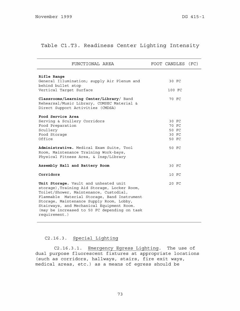
November 1999 DG 415-1
73
Table C1.T3. Readiness Center Lighting Intensity
FUNCTIONAL AREA FOOT CANDLES (FC)
Rifle Range General Illumination; supply Air Plenum and behind bullet stop
30 FC
Vertical Target Surface 100 FC Classrooms/Learning Center/Library/ Band Rehearsal/Music Library, COMSEC Material & Direct Support Activities (CMDSA)
70 FC
Food Service Area Serving & Scullery Corridors 30 FC Food Preparation 70 FC Scullery 50 FC Food Storage 30 FC Office 50 FC Administrative. Medical Exam Suite, Tool Room, Maintenance Training Work-bays, Physical Fitness Area, & Insp/Library
50 FC
Assembly Hall and Battery Room 30 FC Corridors 10 FC Unit Storage. Vault and unheated unit storage),Training Aid Storage, Locker Room, Toilet/Shower, Maintenance, Custodial, Flammable Material Storage, Band Instrument Storage, Maintenance Supply Room, Lobby, Stairways, and Mechanical Equipment Room. (may be increased to 50 FC depending on task requirement.)
20 FC
C2.16.3. Special Lighting
C2.16.3.1. Emergency Egress Lighting. The use of dual purpose fluorescent fixtures at appropriate locations (such as corridors, hallways, stairs, fire exit ways, medical areas, etc.) as a means of egress should be
November 1999 DG 415-1
74
considered as an alternative to dedicated battery pack emergency lighting units. Dual purpose fixtures, which are more economical and do not require special circuitry, incorporate battery back up units and continue to function during power outages. If only battery pack lights are used, they are to be hardwired (not plug-in).
C2.16.3.2. "Instant Restrike Light Source/Night Lights" in Assembly Hall. In addition to the HID light fixtures, an instant restrike light source, such as incandescent, fluorescent or an integral part quartz should be used to supplement the metal halide system and to provide immediate light response. The designer shall determine the most economical type light source to be provided for the project involved in order to ensure adequate light for life safety purposes.
C2.16.3.3. Exit signs. The use of approved self illuminating exit signs is encouraged in locations where illuminated exit signs are required by NFPA 101.
C2.16.3.4. Control. Classroom lighting should be controlled from a point convenient to the speaker, as well as at the door. one dimmer control located at speakers platform may be used for lighting fixtures.
C2.16.4. Power/Wiring
C2.16.4.1. Interior
C2.16.4.1.1. The interior electrical distribution system should be designed for the most efficient and economical distribution of power, using the highest voltage consistent with the load served. A 3-phase 208/120-volt system will generally be the minimum, with consideration given to using a 480/277-volt system where loads are sufficient to justify it. Wiring (including conduit for future communications wiring), junction boxes, and plug-in receptacles may be selected for use in a grid arrangement above the suspended ceilings in large open administrative areas. This is to be used in conjunction with "telephone power pole" systems or a conventional wall and/or floor pedestal outlets. However, the use of floor pedestal outlets

November 1999 DG 415-1
75
reduce or might eliminate future flexibility for room layouts. The "poles" themselves, however, cannot be supported with military construction funds (since they are portable). Wiring/conduit may be labeled or tagged for circuit identification but should not be color code painted. EMT or rigid conduit should be used where required by code. Concealed conduit should be used in administrative areas, corridors, lobby, toilets, classrooms/library, learning center, food preparation and scullery area, physical fitness area, medical areas and may be used throughout the facility.
C2.16.4.2. Ground fault provisions should be in accordance with NFPA 70. Ground fault protection may be used for all receptacles where power tools will be used.
C2.16.4.3. Power panels, telecommunications, and electrical equipment should be located in secure areas free from environmental extremes of temperature, dust and humidity. All equipment must be grounded. Do not use storage rooms or maintenance/custodial areas. Where required, shallow closets or hanging Telecommunications cabinets may be provided. Possible future expansion and/or changes should be considered when sizing and routing conduit.
C2.16.5. The number of duplex convenience receptacles indicated below are generally what could be expected, however, the number of outlets should be reviewed by the state and modified as required for each Readiness Center.

November 1999 DG 415-1
76
TABLE C2.T4. ELECTRICAL RECEPTACLES
FUNCTIONAL AREA NUMBER OF OUTLETS/REMARKS
Rifle Range 2 located behind firing line Unit Storage (Heated and Unheated)
One outlet/each subdivided wire cage area
Vault 1 Food Service Areas Additional 110-volt or 220-volt outlets for
equipment per Appendix 8; w/ ground-fault-protected outlets required in wet areas
Food Storage None Food Preparation 2 Scullery 1 Toilets Male/Female 1 ground fault 110-volt duplex outlet per 2
lavatories, minimum of 1 Maintenance Training Bay 4 additionally; 1 220-volt outlet per bay;
1 28-volt dc outlet per bay (not including converter 1 110-volt or 220-volt outlet for each piece of installed or movable equipment requiring a dedicated outlet; 1 110-volt weatherproof outlet installed just outside the training bay
Flammable Material Storage None Lobby 3 with 1 of the 3 outlets for future trophy
case Exterior of Readiness Center Building
1 Ground fault protected 110-volt waterproof duplex outlet every 150-FT of building periphery
C2.16.5.1. Power for Microprocessors. As long as an adequate number of electrical outlets is provided in areas where microprocessors are to be used, and the circuitry is

November 1999 DG 415-1
77
properly designed to accommodate the anticipated loading, there should be no need to provide special "dedicated" circuit wiring for computer use (RCAS server/printer location is an exception). Electrical power surge and spike protection strips should not be included in the design and construction documents.
C2.16.5.2. The exhaust fan for a battery room is to be interconnected with the charger circuit so the fan always operates when the charger is on. Under these conditions, the fan does not need to be explosion proof.
C2.16.6. Fire Protection
C2.16.6.1. General. Sites for National Guard Readiness Centers will normally have all utility lines, including a water main of adequate size to provide fire protection, available adjacent to the site. Except in cases of conflict with state requirements, exterior fire protection should be in conformance with NFPA requirements. Refer to the mechanical subsection on fire protection for more details on the design and analysis.
C2.16.6.2. Interior
C2.16.6.2.1. Alarm Systems. A manual alarm system should be provided, with a connection to the supporting fire fighting unit. Automatic detection and alarm systems are not normally required or authorized unless required by an applicable code.
C2.16.6.2.2. Fire Extinguisher/Cabinets. Fire extinguishers are classified as portable equipment and addressed under the equipment section.
C2.16.6.2.3. Emergency Egress Lighting. Means of egress emergency lighting should be as defined by NFPA and the special lighting subsection.
C2.16.6.2.4. Exit Signs. Either lighted or unlighted exit signs may be provided in accordance with applicable codes as shown in the special lighting subsection.

November 1999 DG 415-1
78
C2.16.6.3. Sprinkler Protection. See the appropriate Sprinkler Protection subparagraph in the Mechanical for details on the design and analysis.
C2.16.7. Intrusion Detection System (IDS)
C2.16.7.1. New Vault Construction. An IDS is required to be installed in each Readiness Center containing an arms and/or ammunition vault. The IDS shall consist of a Government furnished system, installed by the contractor, and shall include the following:
C2.16.7.1.1. A unit storage room, which gives access to a vault, should have one ultrasonic motion sensor (directed at the vault door); an ultrasonic motion processor; balanced magnetic switches on all doors and operable windows; and a time delay device (with timer and duress capability).
C2.16.7.1.2. A unit storage room, which does not allow access to a vault, does not require an IDS.
C2.16.7.1.3. The arms vault(s) should have a control unit (one per vault); a balanced magnetic switch on the vault door; ultrasonic, infrared, or vibration sensors (to cover entire vault area), and either an ultrasonic, infrared, or vibration processor. If high ultrasonic noise levels prevent use of passive ultrasonic sensors, vibration or passive infrared sensors and corresponding processors should be used.
C2.16.7.1.4. The vault(s) should also have an ultrasonic motion processor; passive infrared sensors, passive ultrasonic sensors or vibration sensors. Include a passive ultrasonic processor (infrared or vibration processor if required). If high ultrasonic noise levels prevent use of passive ultrasonic sensors, vibration or passive infrared sensors should be used.
C2.16.7.1.5. The data transmission system should be located in the control unit. At multi-vault locations, one control unit will house the data transmission system, with the other control units are connected to it by wiring in
November 1999 DG 415-1
79
rigid conduit. The transmitter should be connected through a leased telephone line to a remote monitoring agency.
C2.16.7.1.6. At multi-vault locations, area notification equipment should be installed to indicate which vault control unit is in an alarm condition.
C2.16.7.1.7. An interior audible alarm may be installed at the option of the state (100% federally funded). The design of this system shall be in accordance with NGB-ARI Joint Services Interior Intrusion Detection System (J-SIIDS) Guide Specifications which also provide guidance in connection of the system to an appropriate monitoring agency. A telephone outlet should be provided near the control unit to facilitate testing the system. No federal funding support will be provided for a leased or rented IDS.
C2.16.7.1.8. Rifle Range Storage Room. If a Class V security container is placed in this storage room, a magnetic switch is to be installed on the storage room door, a proximity sensor on the security container, and a time delay device.
C2.16.7.1.9. Intrusion Detection System. All conduit and installation of J-SIIDS equipment is to be listed as a separate bid item for cost accounting computation purposes, J-SIIDS eligible for 100% federal support (as opposed to 75% federal support normally authorized for the Readiness Center itself). A commercial intrusion detection system (CIDS) may be 75% federally supported and a separate bid item is not required.
C2.16.7.2. Alterations to Existing Facilities. There are several options to consider for commercial IDSs in existing vaults when there is an alteration and/or addition project for the Readiness Center. If the existing IDS is in compliance with revised IDS Specifications and the existing equipment is in good working order, it may be retained. If the existing commercial IDS equipment is determined to need replacement, J-SIIDS or a comparable commercial IDS system shall be used. Any questions on commercial IDS or J-SIIDS should be referred to NGB-ARI.

November 1999 DG 415-1
80
C2.16.8. Telecommunications & Cabling
C2.16.8.1. General. At the programming stage of the project, the state Facilities Management Officer is to coordinate with the state Director of Information Management (DOIM) to determine the complete type of telephone system to be installed; then, provide this data to the design agent. Telecommunications cabling plant includes both voice, video and data in a single integrated plant. It will be installed in accordance with All States Log Army National Guard Telecommunication Policy and Services, and as applicable TIA/EIA 568A Standards.
C2.16.8.2. Cable. The cable plant will be a Star Topology with no more than two levels of cross connect. All wiring will be, as a minimum, unshielded twisted four pair "Category Five" cabling, tested to Category Five standards, fiber optic cabling is preferred if funding available. The completed cable plant will be tested and certified as meeting Category requirements. Wiring will be run in conduit separate to sources of electro-magnetic influence and terminated in a telecommunications information closet protected from temperature and humidity extremes.
C2.16.8.3. Specifics
C2.16.8.3.1. Two dual outlets per each small office with both data and voice capability will be provided.
C2.16.8.3.2. In large open bay areas there will be one dual outlet centrally located per 10-FT run.
C2.16.8.3.3. One dual outlet in the supply room near the vault door to facility CIDS/J-SIIDS testing; one dual outlet in the Rifle range, located behind the firing line, and one dual outlet in the vault to support the J-SIIDS.
C2.16.8.3.4. One voice outlet for a public telephone in the lobby.
November 1999 DG 415-1
81
C2.16.8.3.5. The designer should specify on the contract drawings/specifications that the system's outside trenching, plastic conduit and cable to the terminal board in the Readiness Center, the cable trays, outlet boxes, associated wiring, and cabinet mounting board to be contractor furnished and installed, and be Category Five certified. The telephone instruments, modems, and voice data switching equipment are not supportable with MCA construction funds.
C2.16.8.4. Public Address System. Conduit, wiring and equipment may be installed. This system is intended to primarily serve the assembly hall, but should be capable of being heard throughout the facility in order to contact personnel whose exact location is not known at any given moment or who may not be near a telephone and thus cannot be contacted with the telephone intercom capability.
C2.16.8.5. Antenna Base and Lead-In. In those cases where one or more of the units at the Readiness Center are authorized a ground mounted antenna system (either through the TDA or other sources such as the Federal Emergency Management Agency), an antenna concrete base, conduit (with pull wire) leading into the building and outlet should be provided. Also, if antenna mast is roof mounted, a roof mounted base, mounting brackets, guy cable tiedown and conduit may be provided as part of construction. Detailed coordination between the responsible designer, the Military Department, and the using unit will be required to assure that the exact requirements have been identified.
C2.16.8.6. Door Bell. A door bell, if required, may be located at the main entrance from the POV parking area. A remote controlled door latch and opener would not be authorized.

November 1999 DG 415-1
82
C3. CHAPTER 3
ENERGY CONSERVATION
C3.1. GENERAL
All facility equipment, materials, and fuel types in the design process should be selected on the minimum consideration of the least total cost, current and future availability, environmental compatibility, and renewability.
C3.2. PASSIVE SOLAR ENERGY CONSERVATION
Functional areas should, where feasible, be designed and oriented to make use of the principles of passive solar energy design, but specific passive solar features (other than those recognized specifically, herein) would have to be justified on a life cycle cost basis (retain at state and not to be submitted to NGB) demonstrating a payback in 25 years or less before federal support could be obtained. Buildings should be located to utilize winter sun, prevailing winds, and natural land forms. Landscaping and planting should be utilized for shade from summer sun and to block winter winds. If multiple features are proposed, a separate study need not be prepared for each, but the cost for individual items should be separated within the study. Features that are suggested for consideration at Readiness Centers and which may prove to be cost effective are as follows:
C3.2.1. Enclosed unheated vestibules (at high use entries, corridors, main entrance and those used as access to POV parking).
C3.2.2. Screens (including screen walls, shutters and louvers).
C3.2.3. Earth berms(against the exterior walls).
November 1999 DG 415-1
83
C3.2.4. Plantings. Landscaping can reduce direct sun from striking and heating up building surfaces. It can prevent reflected light carrying heat into a house from the ground or other surfaces. By reducing wind velocity, an energy conserving landscape slows air leakage in a house. Additionally, the shade created by trees and the effect of grass and shrubs will reduce air temperatures adjoining the house and provide evaporative cooling.
C3.2.4.1. Design Considerations. "Energy conserving landscapes" reduce energy costs in a home during summer and winter. Ideally, the energy conserving landscape is also a water conserving landscape. It is possible to achieve as much as a 30% reduction in cooling and heating costs through careful landscape planning.
C3.2.4.2. Dense Trees And Shrubs . The use of dense tree and shrub plantings on the west and northwest sides of a home will block the summer setting sun. This is the most effective landscape planting strategy.
C3.2.4.3. Shading. Trees are primary in an energy conserving landscape. Trees can have a canopy large enough to shade roofs, reducing cooling costs and increasing comfort.
C3.2.4.4. Deciduous trees. The best locations for deciduous trees are on the south and east sides of a house. When these trees drop their leaves in the winter, sunlight can reach the house to help in heating the home. Note: Even without leaves, trees can block as much as 60% of the sun, making placement of trees critical to effectiveness.
C3.2.4.5. Evergreen trees. Evergreen trees on the north and west sides afford the best protection from the setting summer sun and cold winter winds.
C3.2.4.6. Large trees. If large trees need to be planted, it is best to select trees that have a moderate growth rate rather than fast growing varieties. Moderate
November 1999 DG 415-1
84
growing varieties are sturdier against storm damage and generally more resistant to insects and disease.
C3.2.4.7. Medium to large size trees. A tree that will reach a medium to large size should be located 15 FT to 20 FT from the side of a house and 12 FT to 15 FT from the corner. Smaller trees can be planted closer to a house and shade walls and windows.
C3.2.4.8. Shrubs. Shrubs or small trees can be used to shade split air conditioning or heat pump equipment that sits outside. This will improve the performance of the equipment. For good airflow and access, plants should not be closer than 3 FT to the compressor.
C3.2.4.9. Vines for Shading. When trees are young and not providing much shade, vines can be used to provide shading on walls and windows. Some vines such as English Ivy will cling to any wall surface. This can harm wood surfaces. Trellises placed close to the walls can be used to support vine growth without touching the walls. Using vines which lose foliage in the winter can be used for summer shading as long as vine stems do not significantly block winter sun. Evergreen vines will shade walls in the summer and reduce the effects of cold winds in the winter.
C3.2.4.10. Absorbent and Reflective Materials. Groundcover and/or turf also has a cooling effect from evapotranspiration (the loss of water from the soil by evaporation and by the transpiration of the plants growing therein). The temperature above a groundcover will be 10 to 15 degrees cooler than above a heat absorbent material such as asphalt or a reflective material such as light colored gravel or rock. A heat absorbent material like asphalt will also continue to radiate heat after the sun has set. It is best to either minimize the use of heat absorbent and reflective materials near a house and/or shade them from any direct sun.
C3.2.4.11. Windbreaks. Evergreen shrubs and small trees can be planted as a solid wall at least 4 FT to 5 FT away from the north side and provide a windbreak. However,

November 1999 DG 415-1
85
it is better to have dense plantings further away so air movement can occur during the summer. The effective zone of protection for a windbreak can be 30 times the height of the trees. However, the maximum protection occurs within five to seven times the tree height. For example, if the windbreak will be 25 FT tall, it should be placed from 125 FT to 175 FT from the house. The Characteristics of an effective windbreak are as follows:
C3.2.4.11.1. The windbreak extends to the ground.
C3.2.4.11.2. Foliage density on the windward side is optimally 60%.
C3.2.4.11.3. 2 to three rows of evergreen trees in staggered order should be used. If using deciduous trees, there should be five to six rows.
C3.2.4.11.4. The length of a windbreak should be 11.5 times the mature width of the stand of trees.
C3.2.4.11.5. The tree heights within the windbreak should be varied.
C3.3. THE BUILDING ENVELOPE
C3.3.1. Wall Insulation. As noted in Chapter 2, the exterior building walls should be insulated to obtain a heat transmission factor (as stated in Table AP1.T1.) for the gross wall value. Achievement of these values will require a comprehensive approach in determining the sizing and location of glazed openings, the glazing system(s) to be used, heat loss at door openings (including use of enclosed vestibules at primary entrances), and the characteristics of the insulation to be used in the roof and the opaque wall section(s). As discussed elsewhere, herein, the calculations used to verify that the proposed wall systems target U-Value has been achieved must be submitted to NGB with the preliminary design (35% completion of contract documents).

November 1999 DG 415-1
86
C3.3.2. Roof Insulation. Also as noted in Chapter 2, the roof assembly should be insulated to obtain a heat transmission factor in Table AP1.T1. in Appendix 1. Calculations concerning this system will also be submitted to NGB along with the preliminary (35%) design documents.
C3.3.3. Doors/Windows. Openings should be sized and located to strike an appropriate balance between energy conservation and functional usage. As noted in Chapter 2, double/triple glazing or insulated glass should be considered, thermal breaks should be provided in the metal frames, and heat absorbing tinted glass of reflective glass should be used where appropriate. All exterior doors are to be insulated.
C3.3.4. Vestibules. Air locks/vestibules should be used at the main entrance and at all corridor entrances/exits leading to POV parking areas at Readiness Centers which are located in climatic zone with a design temperature less than 15°F.
C3.3.5. Earth Embankments/Berms. Embankments/berms may be used where appropriate, provided such usage does not involve an excessive amount of retaining wall type construction at entrances/exits (federal support is not authorized for retaining wall construction at the toe of the embankment; i.e. toe of berm is above adjacent finished grade).
C3.3.6. Weather Stripping/Caulking. Use these items to reduce air infiltration.
C3.3.7. Building Shape. The building should be shaped with as low an exterior surface as practical and economical to reduce heating and cooling costs.
C3.4. HVAC EQUIPMENT
C3.4.1. Fuel selection and types of heating systems are addressed in the Heating subsection of Chapter 2 of this Design Guide for fuel selection and types of heating systems.
November 1999 DG 415-1
87
C3.4.2. Features which should be provided include:
C3.4.2.1. A programmable timer with a capability to preset the appropriate temperature level for occupied and unoccupied usage of the various zones.
C3.4.2.2. An outdoor temperature sensing control to automatically shut off the heating system when the outdoor temperature reaches or exceeds 65°F.
C3.4.2.3. Door closers, where justified, may be installed on exterior and interior doors.
C3.4.2.4. Operable (manual) windows.
C3.4.2.5. Low leakage dampers.
C3.4.3. Features which should be considered, if economical, include:
C3.4.3.1. Multiple boilers.
C3.4.3.2. Destratification fans in assembly hall.
C3.4.3.3. Exhaust hood that supplies untempered make-up air through an outer jacket of the kitchen exhaust hood so only a limited amount of heated room air is exhausted.
C3.5. DOMESTIC HOT WATER
C3.5.1. Features which should be provided include:
C3.5.1.1. Flow restrictors in shower heads.
C3.5.1.2. Low flow aerators in kitchen and lavatory faucets.
C3.5.1.3. Separate water heaters for kitchen and small toilets serving full-time occupancy.

November 1999 DG 415-1
88
C3.5.2. Features which should be considered include:
C3.5.2.1. Outdoor temperature reset control for the water heating systems (to vary water temperature inversely with outdoor temperature).
C3.5.2.2. Time clocks on water heaters serving main toilets and showers.
C3.6. LIGHTING
C3.6.1. Interior. High pressure sodium or metal halide fixtures should be used in the assembly hall (with a separate fluorescent "night light" system), as stipulated elsewhere, herein. Design lighting intensity levels should be established to develop a maintained intensity level approximately equal to the intensity at task level stipulated elsewhere, herein. Energy efficient florescent fixtures with electronic ballast and T8 tubes are authorized.
C3.6.2. Exterior. High pressure sodium or metal halide fixtures, with photo electric and time clock controls as stipulated elsewhere, herein, should be used.

November 1999 DG 415-1
89
C4. CHAPTER 4
ENVIRONMENTAL REQUIREMENTS
C4.1. GENERAL
C4.1.1. Environmental Codes. All current environmental codes, which the laws of the state invoke or incorporate, take precedence where they are more restrictive than applicable Federal requirements as stipulated, in section C1.5 (Codes)of Chapter 1 of this design guide. In order to avoid problems of interpretation, use a "Certification of State Code Requirement", where code interpretations would set a significant precedent, appear to be unusually restrictive, or considered to be inconsistent with similar situations encountered in other states. (See also section C1.5 of Chapter 1, above.)
C4.1.2. Erosion. Appropriate control measures will be employed during construction to comply with the latest federal environmental and state requirements to minimize erosion. (See subsection C2.2.4 of Chapter 2, above.)
C4.1.3. Soils. The completed “Soil Bearing Capacity Declaration” discussed in section C1.4 of Chapter 1, and shown in Appendix 1 of DG 415-5, is used by NGB-ARI to gauge the adequacy of the site and thus determine whether federal funds should be granted for construction of the additional foundations caused by poor soil at that particular location. Special foundations such as wood, steel or concrete piles and concrete grade beams would be supported if the soil investigation survey indicates an alternative should be used and a "Declaration of Uniformity of Area Soil Conditions" is provided as justification. (See also section C1.4, above, and Appendix 2 of DG 415-5.)
Indoor Ranges. Appendix 3 (Indoor Range requirments) of this DG 415-1 sets forth some basic guidelines and provides for a rifle range design which will meet the requirements
November 1999 DG 415-1
90
of the National Guard. Use of these guidelines, in conjunction with heating and ventilation equipment properly sized by the designer, will assure that environmental requirements and all OSHA requirements are satisfied.
C4.1.4. Fuel Storage. The program documents should be consulted for fuel storage and dispensing systems as recommended in subsection C2.2.15 (Fuel Storage and Dispensing System). Appendix 5 (Vehicle Requirements) in DG 415-5 (General Appendicies) shows typical layouts for both single and dual fuel systems for vehicles.
Fuel Storage Tanks. Above ground Storage Tanks (AST) may be used instead of underground Storage Tanks (USTs) if allowed by state/local environmental and safety (fire) codes, as leaks from ATSs are much easier to detect in a timely manner than leaks from USTs. ASTs should be emplaced away from facility boundaries to reduce the likelihood of vandalism. If ASTs are to be used, concrete-encased ASTs are recommended if sufficient capacity and aboveground space are available. (See also subsection C2.2.16.) USTs must meet standards of 40 CFR 280 series and any applicable state codes. Army policy, however, does not recognize the heating oil exclusion for USTs.
C4.1.4.1. Petroleum Dispensing Facilities. All plans for new construction, modification, or upgrading of petroleum facilities containing fuel purchased with Federal funds should be submitted for review and technical assistance prior to bidding as discussed in paragraph C2.2.16.2 of subsection C2.2.16 above. This review is necessary to help ensure that the proposed facilities meet all environmental and safety (especially fire) requirements of regulations. These requirements include clearing vegetation from the area where POL is to be stored, constructing liquid tight dikes surrounding ASTs that exceed 500 gallons in size, and have a fire suppression system, if required by state/local codes.
C4.1.4.2. Wash Platforms (wash racks). Environmental features required by Federal, State and local codes will be

November 1999 DG 415-1
91
included. The method of final disposal of the effluent should be selected from among the following alternatives: surface disposal; subsurface disposal, or recirculation to a closed system (pre-treatment is authorized, if required to meet local standards). (See subsection C3.2.17 of Chapter 3 for Wash Platforms.) The wash platforms are generally 25 FT by 40 FT and 110 SY; however, if there is a justification based on oversized pieces of equipment, the dimension may be adjusted accordingly. The number and size of wash platforms to be included in the construction documents may be obtained from the approved programming documents. Wash platforms should be equipped with settling basins to trap grit and oil equal to 250 CF of water volume plus 50 CF of grit volume per connected wash platform.
C4.2. STORMWATER
Storm Water is addressed in section C2.2 (Site Work) of Chapter 2 of this design guide. The designer should separate normal stormwater sheet flows from possible contaminated stormwater. Non-contaminated flows should be designed to run off, down stream, from contaminated sheetflows. DG 415-5 Appendix 6 (Stormwater Pollution Prevention) provides additional guidance for contaminated sheetflow management including bio-retention ponds, retention basins and grit interceptors. Oil water separators will be authorized Federal support if recommended by the SWMP (Storm Water Management Plan) and the National Pollutant Discharge Elimination System(NPDES)requirements, and permitted by state/local codes.
C4.3. UTILITIES
The designer should verify that all utility services will be available at the site as mentioned in subsection C2.2.23 (Utilities). The contract documents should stipulate that the contractor is to coordinate with local utility companies on the division of work to the extent necessary to assure that when the facility is completed, all utility

November 1999 DG 415-1
92
services will be connected and operational without further cost.
C4.4. ASBESTOS REMOVAL
C4.4.1. An asbestos survey should have been accomplished for all Readiness Centers that are programmed or planned for any combination of alteration, rehabilitation and addition to establish the amount, location and estimated cost of asbestos removal. If only a portion of an existing building requires alteration and rehabilitation, all the friable asbestos that would potentially be affected in the building is to be removed prior to the beginning of the alteration and rehabilitation parts of the project.
C4.4.2. The cost of the survey, removal and disposal of asbestos will be 100% federally supportable. DD Form 1390/1391 should include a rough estimate for asbestos removal as a separately listed item of work in the detail estimate. In the transmittal letter to NGB-ARI indicate there is an asbestos problem and authorization to do an asbestos survey and design for removal is urgently needed.
C4.4.3. Coordinate with NGB-ARE-PC Environmental Division (Compliance and Restoration Branch), the State environmental section and NGB Safety And Occupational Health Branch, Industrial Hygiene Team, as a pressing issue is one of responsibility for funding of asbestos-related issues. At present, NGB Environmental pays for asbestos surveys, and disposal of hazardous waste (such as removed asbestos), but not for the labor involved in removing the asbestos form the structure.

November 1999 DG 415-1
93
C5. CHAPTER 5
NATIONAL GUARD BUREAU DESIGN REVIEW REQUIREMENTS
C5.1. PURPOSE
NGB-ARI design reviews are intended only to identify those features which do not qualify for Federal support under the scope authorized on the approved programming documents and criteria in excess to that stated in this document and items which are excessively costly. If serious discrepancies and deficiencies or under-designs are noted during the review, they may be picked up and then pointed out in the comments, but this is not the intent of the review process; responsibility for technical and functional adequacy rests with the responsible designer and the state.
C5.2. SPECIAL REQUIREMENTS DURING DESIGN
Documentation of certain design features and procedures are required by NGR 415-5 and necessary before NGB-ARI will authorize the release of Federal construction funds. These include the: Site Survey Report (paragraph 3-12), Vicinity Sketch (paragraph 4-3) and Location Map (paragraph 4-4). The Site Survey Report includes the Declaration of Soil Bearing Capacity and Declaration of Uniformity of Area Soil Conditions (see respective Appendix 1 and Appendix 2 of DG 415-5 (General Appendices)). Paragraphs 4-5 through 4-8 require Cost Estimates, copies of the Construction Documents, Heat Transmission Factor Calculations,(Appendix 1 of this DG 415-1), and the Bid Form (DG 415-5 Appendix 3). Prior to the solicitation of bids, one copy of the final project documents to be used for bid solicitation is to be submitted to NGB-ARI as a record file of the actual project that is to be constructed. These documents should be completely revised in conformance with the previous NGB-ARI review comments so that the need to issue Addenda during the bidding process is minimized. The transmittal

November 1999 DG 415-1
94
memorandum for the bid documentation should reference and address each NGB-ARI final review comment.
C5.3. REVIEW CHECKLIST.
A Checklist as an aid to check specific items which will be reviewed by NGB has been included as DG 415-5 Appendix 4 (Design Review Checklists). Expeditious approval and authorization of Federal support is contingent on assurance that all items on the checklists, as a minimum, have been scrutinized and are in compliance with the respective criteria.