df-35 instruction manual - accuphase · instruction manual please read this manual and the separate...
TRANSCRIPT

INSTRUCTIONMANUAL
Please read this manual and the separate ImportantSafety Instructions thoroughly before use, and retainthese documents for future reference.
DIGITALFREQUENCY
DIVIDINGNETWORK
DF-35

1. Naming of PartsFront Panel / Rear Panel ………………………………… 1Filter Amplifier Unit ………………………………………… 23-Way Amplification System or Greater Configurations… 2Verify that Supplied Accessories are Complete ………… 2
2. Warnings/ Precautions ………………… 33. Parts and Function………………………………4, 54. Operations
Input Selection………………………………………………6Filter Amplifier Unit Overview ………………………………6Basic Display Settings ………………………………7~10
Selection of Previously Registered Characters ……10Independent Character Setting………………………10
Filter Amplifier Unit Initial Settings Display ………………11To Return to the Initial Settings Display
after Making Function Changes... …………11Set DELAY Separately for Left and Right Speakers ……11Accessing the Function Settings Memory ………………12Function Safety Lock (Setting and Canceling) …………12How to Install the DN-35 Filter Amplifier Unites…………13
5. How to Interconnect UnitsInput Connections
Analog Input …………………………………………14Digital Input � ………………………………………15Digital Input � ………………………………………16
Examples for Connecting to Multi-Channel Amplifiers 172-Way Amplification System ……………………18, 193-Way Amplification System ……………………20, 214-Way Amplification System ……………………22, 235-Way Amplification System ……………………24, 25Subwoofer System ………………………………26, 27
6. Option BoardsWhen Interconnecting with an Analog Preamplifier ……28Digital Connection from DC-330…………………………28
7. Technical DiscussionTime Alignment and the DELAY Function ………………29Phase Relations ……………………………………30~32Level Adjustments…………………………………………32Speaker Measurement with the DG-28 …………………33
8. Guaranteed Specifications ………………………349. Performance Curves………………………………35
10. Block Diagram ……………………………………36
This mark indicates an important instructionthat must be observed to prevent the possibilityof death or injury to persons or severe damageto the unit. To ensure safe use of the product,make sure that such instructions are fullyunderstood and observed.
About the mark
Thank you for purchasing this Accuphase product, which is anothermanifestation of our efforts to create the highest quality audiocomponents. The strictest control was exercised throughout our entiremanufacturing process in producing this component — from basicresearch, the selection of each part, assembly, testing, data recording,up to packing and shipping — so that we supply a product with everyconfidence that it will provide full satisfaction and pride in ownership.
We are pleased to heartily welcome you to the fast-growingAccuphase circle of distinguished audio enthusiasts and devotees oftrue sound.
Contents
Warning:Disregarding instructions bearing thismark incurs the risk of death or severeinjury.
Caution:Disregarding instructions bearing thismark incurs the risk of l ight injury topersons or damage to the product.

1
SUBWOOFER Output SelectorSwitch (page 5)
6
●●●●
1. Naming of Parts
Front Panel
Rear Panel
Cutoff frequency(Frequency and slope can be independently set for each channel)
Channel 1(LOW Range)
Channel 2(HIGH Range)
POWER Switch(page 4)
1
INPUT Selector Switch(pages 4, 6)
2
BALANCED OutputConnectors (page 4)
4 UNBALANCED OutputConnectors (page 5)
5
INPUT - COAXIAL DigitalInput Connector (page 5)
7
OUTPUT - COAXIALDigital OutputConnector (page 5)
8
Option boardextension slots (pages 5, 26)
9
AC power connector(page 5)
10
Filter Amplifier Unit
●
●
●●●●
● ●
●●●●●●●●
●●●●●●●●
3Filter amplifier unit (DN-35)extension slots (page 13)
Channel 1 Channel 2
Channel 2analog output
Channel 1analog output
Filter amplifier unit extensionslots (insert from front panel)
(page 13)
(pages 2, 4, 6 ~ 13)LOCKEDLED lights when locked
●
※ The DF-35 unit can function as a 2-wayamplification system by using the twoDN-35 filter amplifier units that areincluded as standard equipment.

2
Filter Amplifier Unit
ENCODER
(PUSH ENTER)
FUNCTION
LOWERFREQUENCY (Hz)
LOWERSLOPE (dB/oct)
LEFTLEVEL (–dB)
DELAY (cm)
OUTPUT
UPPERFREQUENCY (Hz)
UPPERSLOPE (dB/oct)
RIGHTLEVEL (–dB)
PHASE
ASSIGNMENT
1 LOWER FREQUENCY
Lower cutoff frequency (Hz)
3 LOWER SLOPE
Lower slope characteristic (dB/oct)
5 LEFT LEVEL
Left channel level (dB)
7 DELAY
Delay transmission distance (cm) Set separately for left and right channels
9 OUTPUT
Output ON/OFF
A FUNCTION
Function selector knob (Turn to light LEDs ① ~ ⑩)
C Display Window
2 UPPER FREQUENCY
Upper cutoff frequency (Hz)
4 UPPER SLOPE
Upper slope characteristic (dB/oct)
6 RIGHT LEVEL
Right channel level (dB)
8 PHASE
Phase switch
10 ASSIGNMENT
Character display
B ENCODER
Parameter selector knob
As you turn the knob, each function setting appears in the display window . Push the knob to enter Function Memory, Function Safety Lock and other settings.
C ( )
3
3-Way Amplification System or Greater Configurations
● Increase the number of filter amplifier units (DN-35).
● One DF-35 unit can be used for up to a 4-way configuration.
● 5-way or greater configurations require extra DF-35 units
(see page 24).
3-Way Amplification System (see page 20)
HIGH Range
LOW Range
MID Range
4-Way Amplification System (see page 22)
LOW-MID Range
HIGH Range
LOW Range
MID Range
(see pages 7 ~ 12 for details of operations)
Add one DN-35 unit
Add two DN-35 units
DN-35 filter amplifier unit
● Instruction manual ……………… 1● Important Safty Instructions …… 1●AC power cord (2 m) …………… 1
Verify that Supplied Accessories are Complete

Warnings
Use only signals from the OUTPUT connector of an additionaldigital output board installed in a DC-330 OUTPUTS slot asdigital input to the DF-35. Do NOT input digital signals fromany other source.
The following connections can cause speaker damage owingto full level signal input to the DF-35 without the DC-330'svolume data.
▼ DC-330 OUTPUTS slot DG-28 DF-35 DigitalConnection▼Digital output from a source other than the DC-330
OUTPUTS slot.▼Digital output from a CD player or other digital audio
equipment.
Use only analog audio equipment such an analog pre-amplifier through which volume is routed for analog inputsignals to the DF-35.
The following connections will cause speaker damage, sincethe full level signal is input directly to the DF-35 withoutvolume control.
▼The analog output connector of a CD player or otheraudio equipment.▼The recording (REC) output connector of a pre-amplifier,
etc.▼The analog output signal of an added optional circuit
board such as the DC-300/DC-330.
Precautions
● Do not change the cutoff frequency, slope characteristic orother functions while the speakers are active, as severesignal fluctuations can cause unwanted noise or shocknoise.
● Particularly in the case of active tweeters and midrangedrivers, if you change to a cutoff frequency below theLOWER cutoff frequency setting, the inordinately largeoutput to the speakers could exceed the speakers'permissible input level and result in speaker damage. Takecare, therefore, when setting below the rated cutofffrequency.
● Do not switch off the power within 1 seconds of makingfunction changes, since the changes you made will not bestored in memory.
● Turning the FUNCTION and ENCODER knobs is an easyway of making a variety of setting changes. Use theSAFETY LOCK to avoid making mistakes or settingalterations that cause unwanted noise.
■ Be sure to turn off the power before connecting/disconnecting any input/output cable.
■ Be sure to turn off the power when inserting or removinga DN-35 filter amplifier unit or optional circuit board.
3
2. Warnings
■Be sure to connect the power cord of theDF-35 only to an AC outlet rated for thevoltage shown on the rear panel. ●This unit can be used in areas with an AC line frequency
of 50 or 60 Hz.
■Handle the power cord with care, to avoidthe danger of electric shock.●Do not nick or excessively bend the cord, and do not
place heavy objects on it.●When removing, always grasp the plug. Do not pull at
the cord.●Never touch the plug with wet hands.●Do not use the suppl ied power cord for other
equipment. Do not use the DF-35 with any other thanthe supplied power cord.(Using a cord with a different rating or plug configurationposes a fire hazard and other risks.)
■When not using the unit for a long time,disconnect the power cord from the AC outlet.
■Never remove the top or bottom cover ofthe unit. Touching any part inside the unitinvolves the risk of electric shock and maydamage the unit.
■Replacing the feet of the unit is dangerous.If the mount screws touch internal parts,this could Iead to electric shock or damage.
■After turning the power off, do not set thepower switch immediately to ON again(within 10 seconds).
■Contact your Accuphase dealer or anauthorized service station in any of thefollowing cases:●If liquids or chemicals were spilled into the unit.●If a foreign object (such as a small pin, nail, coin, etc.)
has entered the unit.●If you notice any unusual circumstances, including smell
or smoke.
Please read this manual and the separate Important Safety Instructionsthoroughly before use, and retain these documents for future reference.
Digital Input
Analog Input
Filter Amplifier Unit Operation

POWER Switch
Push this push-button switch to turn the power On. Pushthe switch again to turn the power Off. For about 2.5seconds after Power On until the internal circuitrystabilizes, the muting circuit operates and thus there is nooutput from the DF-35 during this period.
※The operations and functions that you set beforeturning the power off will be memorized even when thepower is off.
INPUT Selector Switch
Use this selector switch to select the rear panel'sCOAXIAL input and input from the optional slots. An LEDlights when you lock on a digital signal. (See page 6).
COAX: Selects COAXIAL input provided as standardequipment on the rear panel.
1, 2, 3, 4: Selects in order inputs from the optional slots.
DN-35 Filter Amplifier Unit
See pages 7 ~ 13 for a detailed description of operations.
FUNCTION Selector Knob
Use this selector knob to select each type of settingwithin the divided audio frequency range. Turn the knobclockwise and counterclockwise to select functions 1 ~10 and parameters. The LED of a selected item lightsand the content of the selection is indicated in thedisplay window
ENCODER - Parameter Selector Knob
Use this selector knob to select the number and settingof items selected with FUNCTION selector knob .Press the knob to use each function memory and safetylock, etc. (See page 12).
Display Window
This displays each function in the frequency bandselected with FUNCTION selector knob . (See page11 for factory display settings.)
LOWER FREQUENCYThis sets the lower cutoff frequency of the audioband.
UPPER FREQUENCYThis sets the upper cutoff frequency of the audioband.
LOWER SLOPEThis sets the attenuation slope characteristic of thelower cutoff frequency.
UPPER SLOPEThis sets the attenuation slope characteristic of theupper cutoff frequency.
LEFT LEVELThis sets the left channel level.
RIGHT LEVELThis sets the right channel level.
DELAYConverts the delay transmission time of sound todistance (cm) and displays it. Set the value separatelyfor left and right channels.
PHASEUse this selector switch to change the phase of theoutput.
OUTPUTUse this selector to turn ON/OFF analog output withinthe frequency range.
ASSIGNMENTUse this selector to make selections from amongthose registered for display. You can also use thisselector to enter optional character strings. The ASSIGNMENT display lights up automaticallywhen the power is turned On.
BALANCED Output Connectors
These connectors provide balanced transfer outputs thatare strong against exterior inductance noise. Theconnectors enable excellent audio signal transmissionwhen the power amplifier's input connectors are balancedinputs. The pin polarities are as follows:
�:Ground�:Inverted (–)�:Non-inverted (+)
● Accuphase sells audio cable designed for use withthese connectors.
A
A
C
4
3. Parts and Function
2
1
3
4
1 2
3
A
1
2
3
4
7
6
5
8
9
10
B
C

5
UNBALANCED Output Connectors
Use these output connectors when you are using regularpin plug type audio cable for output.
Subwoofer Output Selector Switch
Use this switch to select the Subwoofer mode when youconfigure a multi-amplification system using a subwoofer.(See pages 26, 27.)
NORMAL:Normally leave the switch in this position when youdo not intend to use the subwoofer system (Normalmode).
SUB WOOFER:Set the switch in this posit ion to producemonophonic signals by mixing left and right signalsoutput from the filter amplifier unit. Because thesame signal will be output from both the LEFT andRIGHT channels, connect either of the two outputsto a power amplifier (which may be a monophonicpower amplifier).
INPUT-COAXIALDigital Input Connector
This connector allows coaxial cable input of digital outputsignals from the output connector of a DC-330 boardadded to the OUTPUTS slot.
OUTPUT-COAXIALDigital Output Connector
Use these connectors to transmit input signals when youconfigure a 5-way amplification or further expandedsystem using an extra DF-35 unit. The connectors outputdigital signals via coaxial cable. The volume signal isoutput at the same time.
OPTION 1, 2 Option Board Extension Slots
Use these slots to add option boards for analog or digitalinput. Connect to preamplifier output when installing anadditional board.● See page 28 for available board types.
AC INLET
Insert the supplied power cord into this connector andplug the other end into a wall AC outlet.
WARNING
WARNING
5
6
7
8
9
10
Subwoofer SystemThe subwoofer system is also referred to as the three-dimensional (3D) system. By making use of thephysiological nature of the human auditory system and itsinability to sense the directivity of acoustic frequencieslower than 100 Hz, this system reproduces sounds byplacing a speaker dedicated to ultra-low frequenciesbetween the left and right stereo (not necessarily at thecenter) speakers to mix left and right sounds of low pitch.
● Do not use the unit with any other than the suppliedpower cord.
● The shape of the AC inlet and the plug of thesupplied power cord depend on the voltage ratingand destination country. Using any other type ofcable except the supplied power cord poses the riskof fire and damage.
● This product is available in versions for 120/230 VAC. Make sure that the voltage shown on the rearpanel matches the AC line voltage in your area.
● Opening the unit involves a severe risk of electricshock.
● If the unit does not operate, the internal fuse mayhave blown. Never attempt to replace the fuseyourself. Be sure to contact your Accuphase dealeror an authorized service station.

6
The LED (INPUT LOCKED) above the INPUT selector switch lights when you lock on an input signal.
■<COAX> PositionSet the selector switch to this position for digital (COAXIAL) input.
■<1 ~ 4> Positions (Added Optional Circuit Boards)Set the INPUT selector switch in sequence from positions 1 ~ 4 as shown in the following tablewhen taking input from added optional boards.
The DF-35 uses one DN-35 filter amplifier unit for one part of the audio frequency range, allowingsetting of low-pass filter, high-pass filter and band-pass filter. The DF-35 is provided with two filteramplifier units as standard equipment, which enables the configuration of a 2-way amplificationsystem. For 3-way amplification or greater systems, you must add DN-35 units accordingly.
4. Operations
INPUT(● LOCKED)�
COAX
1 2 34
23
1
1 2 OPTION
1
1 2 OPTION
12
1 2 OPTION
12
1 2 OPTION
312
1 2 OPTION
1
1 2 OPTION
12
1 2 OPTION
34
INPUT(● LOCKED)�
COAX
1 2 34
Lit
INPUT(● LOCKED)�
COAX
1 2 34
Lit
INPUT(● LOCKED)�
COAX
1 2 34
Lit
INPUT(● LOCKED)�
COAX
1 2 34
Lit
INPUT(● LOCKED)�
COAX
1 2 34
Lit
INPUT(● LOCKED)�
COAX
1 2 34
Lit
INPUT(● LOCKED)�
COAX
1 2 34
Lit
INPUT(● LOCKED)�
COAX
1 2 34
Lit
INPUT(● LOCKED)�
COAX
1 2 34
Lit
Input No.
1
2
3
4
Input connector examples�Circled ○ number is the input selector switch position�
�
INPUT selector switch position�(LED lights for locked position)
AI-U1AI2-U1DIO-ST1D1-BNC1
DIO-OC1 AI-B1AI2-B1DIO-PRO1DI2-HS1
Type of option
1
1 2 OPTION
2
1
1 2 OPTION
One-input option Two-input option Option using two slots
INPUT(● LOCKED)�
COAX
1 2 34
Lit
Locked on ①�
Locked on ①� Locked on ②�
Locked on ①�Locked on ②�Locked on ③�
Locked on ①�Locked on ②�Locked on ③� Locked on ④�
From DC-330OUTPUTS slot
LED lights withselector at theCOAX position
Input Selection
Filter Amplifier Unit Overview
PRECAUTIONS※Because analog input boards lock
in with the board's A/D converter,the LED lights irrespective ofboard connection.
※With digital input boards, the LEDwill not light if the digital signal isnot input to its connector.

7
※When configuring your system, please refer to pages 29 ~ 32 with regard to speaker unit delay(DELAY), PHASE, SLOPE characteristic and other settings.
The following shows a setting display example for each function in a 3-way amplification system usingone extra DN-35 filter amplifier unit for channel 3.
ENCODER
(PUSH ENTER)
FUNCTION
Channel 3HIGH Range
High-pass
Norm
On
High
Selects from 59 frequencies
Variable from 0 ~ – 40 dB (in 0.1-dB steps)
0 ~ 999 cm (in 1-cm steps) Up to 700 cm for signals of sampling frequency 176.4 kHz or greater
Norm (Normal) / Inv (Inverted)
On/Off setting
② UPPER FRE- QUENCY (Hz)
④ UPPER SLOPE (dB/oct)
⑥ RIGHT LEVEL (dB)
① LOWER FRE- QUENCY (Hz)
③ LOWER SLOPE (dB/oct)
⑤ LEFT LEVEL (dB)
Pass
– – – –
0.0
500
96
0.0
500
96
12.5
8000
96
12.5
8000
96
25.0
Pass
– – – –
25.0
( )
Selects from 6 dB/oct, 12 dB/oct, 18 dB/oct,24 dB/oct, 48 dB/oct, 96 dB/oct.
L 0R 0
L 15R 15
L 23R 23
Turn to select the desired number
Channel 1LOW Range
Low-pass
Norm
On
Low
Channel 2MID RangeBand-pass
Norm
On
Mid
Details of displayed function Turn to select functions ①~⑩ (LED lights)
⑦ DELAY (cm)
⑧ PHASE
⑨ OUTPUT
⑩ ASSIGNMENT
ENCODERENCODER
(PUSH ENTER)(PUSH ENTER)
FUNCTIONFUNCTION
LOWERLOWERFREQUENCY (Hz)
LOWERLOWERSLOPE (dB/oct)
LEFTLEVEL (–dB)
DELAY (cm)
OUTPUT
UPPERFREQUENCY (Hz)
UPPERSLOPE (dB/oct)
RIGHTLEVEL (–dB)
PHASE
ASSIGNMENTASSIGNMENT
ENCODERENCODER
(PUSH ENTER)(PUSH ENTER)
FUNCTIONFUNCTION
LOWERLOWERFREQUENCY (Hz)
LOWERSLOPE (dB/oct)
LEFTLEVEL (–dB)
DELAY (cm)DELAY (cm)
OUTPUT
UPPERFREQUENCY (Hz)
UPPERSLOPE (dB/oct)
RIGHTLEVEL (–dB)
PHASE
ASSIGNMENT
ENCODERENCODER
(PUSH ENTER)(PUSH ENTER)
FUNCTIONFUNCTION
LOWERLOWERFREQUENCY (Hz)
LOWERLOWERSLOPE (dB/oct)
LEFTLEVEL (–dB)
DELAY (cm)
OUTPUT
UPPERFREQUENCY (Hz)
UPPERSLOPE (dB/oct)
RIGHTLEVEL (–dB)
PHASE
ASSIGNMENTASSIGNMENT
Cutoff frequency500 Hz
LOW Range HIGH Range
96dB/octave
8000 Hz
96dB/octave
MID Range
PASSPASS
Channel 1 Channel 2 Channel 3(add)
Setting Example
23cm
15cm
Tweeter
Mid-range
Woofer
Diaphragm position of each driverwith reference to the woofer position
(Same for left and right speakers)
Basic Display Settings
Display Example
Speaker Example

8
①② LOWER/UPPER CUTOFF FREQUENCY
This sets the unit's cutoff frequency from LOWER through UPPER portions of the audio frequencyrange. Settings are as follows:
LOW Range: PASS/500 Hz (low-pass filter)MID Range: 500 Hz/8000 Hz (band-pass filter)HIGH Range: 8000 Hz/PASS (high-pass filter)
The term in the above means that filtering is not applied and the signal is allowed to passas is.
Precaution: When LOWER range and UPPER range cutoff frequencies conflict (i.e., whenLOWER range ≧ UPPER range), the frequency display window flashes towarn you of the discrepancy.
③④ LOWER/UPPER SLOPE Characteristic
This control sets the attenuation slope characteristic for LOWER and UPPERrange cutoff frequencies. As with cutoff frequencies, the attenuation slopecharacteristic can be set separately for each unit.Which of the attenuation slope characteristics you should choose dependson the speaker system you use or your preference for sound. You shouldmake a decision based on listening tests.If FREQUENCY (cutoff frequency) is , the slope characteristic cannotbe set and the display window flashes.
Cutoff Frequencies (Hz)10 20 31.5 35.5 40 45 50 56 63 71
80 90 100 112 125 140 160 180 200 224
250 280 290 315 355 400 500 560 630 710
800 900 1000 1120 1250 1400 1600 1800 2000 2240
2500 2800 3150 3550 4000 5000 5600 6300 7100 8000
9000 10k 11.2k 12.5k 14k 16k 18k 20k 22.4k
Displays thefollowing
frequencies
11.2k→11k212.5k→12k522.4k→22k4
Cutoff Frequencies
The DF-35 uses the range 31.5 Hz ~ 22.4 kHz with a series of 1/6 octave intervals (ISOstandard). Cutoffs at 10 Hz, 20 Hz and 290 Hz are provided as exceptions. The 10 Hz and20 Hz cutoff frequencies act as subsonic noise filters. If the speaker system you use is a finished product, its cutoff frequency (e.g., crossoverfrequency at LOW range and HIGH range) is specified by the manufacturer. Therefore, thespeaker system should, as a rule, be used at the specified cutoff frequency. However, thisfrequency need not be observed so strictly: a deviation of ±10% from the specified frequencyhas negligible effect on the sound quality.However, when using a horn speaker at higher than LOW-MID range, be sure that the cutofffrequency does not become lower than the specified cutoff frequency. This precaution isnecessary because with a horn speaker the sound reproduction limit (i.e., the flare cutofffrequency) of the speaker horn has been predetermined, and thus the horn speaker isintended for use at the cutoff frequency at least one octave higher than the flare cutofffrequency. Should the cutoff frequency be lowered to the vicinity of the flare cutoff frequency,sounds with a tone unique to the horn will be output, and the produced sounds may lackenergetic continuity in tone with the range below.
Selectable Attenuation Slope Characteristics
6dB/oct, 12dB/oct, 18dB/oct, 24dB/oct, 48dB/oct, 96dB/oct
6dB/oct
96dB/oct
6dB/oct
96dB/oct
LOWER UPPER
Pass Pass
Frequency

9
PRECAUTIONSWith cutoff frequencies of 10 Hz and 20 Hz, the only available attenuation slopecharacteristics are 6 dB/oct, 12 dB/oct and 18 dB/oct.
● are not displayed.● If you set an attenuation slope characteristic of 24 dB/oct or greater with a cutoff
frequency of 31.5 Hz or greater, when you turn the FUNCTION selector knob to 10Hz or 20 Hz, the slope characteristic will be automatically set at 18 dB/oct. (Pleasereset the slope characteristic when you return to a frequency of 31.5 Hz or greater.
⑤⑥ LEFT/RIGHT LEVEL Controls
These controls set the output level separately for left and right channels of each unit. See page 32for an account of level adjustment.
⑦ DELAY (Delay Transmission Time)
If your speakers contain more than two drivers, the speaker diaphragm positions will be out ofalignment with each other. Consequently, if each speaker driver is driven simultaneously, there willbe a time difference between drivers for sound arriving at the ears. Adjustment of this timedifference is known as time alignment (see page 27). The DF-35 incorporates a DELAY functionthat allows time adjustment for sound reaching the ears.Delay is the electrically delayed time from the time taken for sound to reach a certain distance. Forsimplicity, the DF-35 converts the delay time to distance (cm) and displays the distance. In thecase of the speaker example shown on page 27, the diaphragms of the three drivers are out ofalignment with each other. Since the woofer is deepest within the speaker cabinet, it is subject tothe most delay, so the woofer diaphragm position is taken as the reference position of 0 cm.Although measurement is not strictly accurate, the distance to another diaphragm is measured incm units. In this setting example, the channel 1 woofer position is the reference position of 0 cm,the channel 2 mid-range is at 15 cm and the channel 3 tweeter is at 23 cm.With horn speakers, the location of the sound source is not a diaphragm, and the resonant part ofthe horn changes depending on frequency. The DF-35 allows you to make settings in 1 cm units,so adjust the delay time of each filter amplifier unit with the DELAY control while conductinglistening tests for each adjustment until you attain satisfactory delay.Set DELAY separately for right and left speakers (see pages 11 and 29).
⑧ PHASE Selector Switch
See pages 30 ~ 32 for setting details.
⑨ OUTPUT SwitchThe output of each filter amplifier unit can be switched ON and OFF. Use this switch whenchecking your speakers; otherwise you should normally leave the switch in the ON position.
A

10
⑩ ASSIGNMENT (Character Display)
Allows you to select and display characters you previously registered. ASSIGNMENTallows you to independently set a display of 4 characters of your own choosing.
Turn the ENCODER knob to select the characters you want.
� Turn ENCODER knob and select character entry mode (thecharacters entered on the previous occasion are displayed).
� Press ENCODER knob and the fourth character position on the displayflashes.
� Turn ENCODER knob to select a character you want.
� Turn FUNCTION selector knob clockwise and the third character positionon the display flashes.
� Turn ENCODER knob to select a character you want. Repeat these steps
in the same way for setting of characters 2 and 1.
� After entering the characters, press ENCODER knob . The next time youselect character entry mode, the characters you entered on this occasion willbe displayed. The characters will be retained in memory after the power isturned OFF.
B
B
AB
B
B
●Independent Character Setting
B
●Selection of Previously Registered Characters
Registered Characters
(Counterclockwise) Turn ENCODER knob (Clockwise)
(Super Low) (Low Mid) (Mid High) (Super High)〔Character entry mode〕
BDisplays characters previously entered
(initial setting is blank)
Selectable Characters (Total: 70characters)
Upper-case characters
Lower-case characters
Digits
Symbols
(Blank) (Fully lit)
………
………
ENCODER
(PUSH ENTER)
FUNCTION
LOWERFREQUENCY (Hz)
LOWERSLOPE (dB/oct)
LEFTLEVEL (–dB)
DELAY (cm)
OUTPUT
UPPERFREQUENCY (Hz)
UPPERSLOPE (dB/oct)
RIGHTLEVEL (–dB)
PHASE
ASSIGNMENT
B ENCODER
1st character position
Flashing
2nd character position
3rd character position
4th character position
ASSIGNMENT
A FUNCTION
Display Window
11
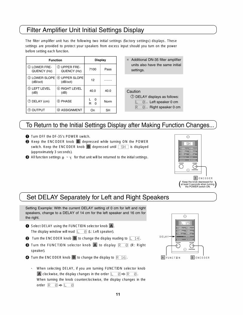
The filter amplifier unit has the following two initial settings (factory settings) displays. Thesesettings are provided to protect your speakers from excess input should you turn on the powerbefore setting each function.
Filter Amplifier Unit Initial Settings Display
② UPPER FRE- QUENCY (Hz)
④ UPPER SLOPE (dB/oct)
⑥ RIGHT LEVEL (dB)
⑧ PHASE
⑩ ASSIGNMENT
① LOWER FRE- QUENCY (Hz)
③ LOWER SLOPE (dB/oct)
⑤ LEFT LEVEL (dB)
⑦ DELAY (cm)
⑨ OUTPUT
7100
12
40.0
L 0R 0
On
Pass
– – – –
40.0
Norm
SH
Function Display
� Turn OFF the DF-35's POWER switch.
� Keep the ENCODER knob depressed while turning ON the POWERswitch. Keep the ENCODER knob depressed until is displayed(approximately 3 seconds).
� All function settings ① ~ ⑩ for that unit will be returned to the initial settings.
BB
To Return to the Initial Settings Display after Making Function Changes...
※ Additional DN-35 filter amplifierunits also have the same initialsettings.
Setting Example: With the current DELAY setting of 0 cm for left and rightspeakers, change to a DELAY of 14 cm for the left speaker and 16 cm forthe right.
� Select DELAY using the FUNCTION selector knob .
The display window will read (L: Left speaker).
� Turn the ENCODER knob to change the display reading to .
� Turn the FUNCTION selector knob to display (R: Right
speaker).
� Turn the ENCODER knob to change the display to .
※ When selecting DELAY, if you are turning FUNCTION selector knob
clockwise, the display changes in the order .
When turning the knob counterclockwise, the display changes in the
order .
A
B
A
B
A
Set DELAY Separately for Left and Right Speakers
ENCODER
(PUSH ENTER)
FUNCTION
LOWERFREQUENCY (Hz)
LOWERSLOPE (dB/oct)
LEFTLEVEL (–dB)
DELAY (cm)
OUTPUT
UPPERFREQUENCY (Hz)
UPPERSLOPE (dB/oct)
RIGHTLEVEL (–dB)
PHASE
ASSIGNMENT
B ENCODERKeep the knob depressed for
at least 3 seconds when turning the POWER switch ON.( )
ENCODER
(PUSH ENTER)
FUNCTION
LOWERFREQUENCY (Hz)
LOWERSLOPE (dB/oct)
LEFTLEVEL (–dB)
DELAY (cm)
OUTPUT
UPPERFREQUENCY (Hz)
UPPERSLOPE (dB/oct)
RIGHTLEVEL (–dB)
PHASE
ASSIGNMENT
B ENCODERA FUNCTION
DELAY
Caution⑦ DELAY displays as follows:
…Left speaker 0 cm…Right speaker 0 cm

12
Functions can be easily set using FUNCTION selector knob and ENCODERknob . For this reason, a safety lock is included to prevent another personfrom changing your function settings by turning the knobs by mistake orthrough carelessness.
� Select ASSIGNMENT with FUNCTION selector knob .
� Keep the ENCODER knob depressed for two seconds.Either the or display will flash. With ENCODER knob depressed
Turn clockwise for (Locked setting)Turn counterclockwise for (Unlocked setting)
� Three seconds after setting to locked mode, the display will change from
back to ASSIGNMENT.
� After setting to locked mode, if anyone turns the FUNCTION selector knob
or ENCODER knob , the display will flash for 3 seconds, and
the set functions will be retained.
BA
B
BA
BA
Function Safety Lock (Setting and Canceling)
ENCODER
(PUSH ENTER)
FUNCTION
LOWERFREQUENCY (Hz)
LOWERSLOPE (dB/oct)
LEFTLEVEL (–dB)
DELAY (cm)
OUTPUT
UPPERFREQUENCY (Hz)
UPPERSLOPE (dB/oct)
RIGHTLEVEL (–dB)
PHASE
ASSIGNMENT
B ENCODERA FUNCTION
ASSIGNMENT
※ Since the setting is for this unitalone, you must repeat the samesetting for all units that you use.
…Unlock
Memories 1 and 2 in each unit have the functions and , which referto memory-read and memory-write respectively.
� Select OUTPUT using the FUNCTION selector knob .
� Keep the ENCODER knob depressed for two seconds.
� For five seconds, either the or display will flash. Turn theENCODER knob during this period to select one or the other anddetermine the selection by pressing ENCODER knob .
� If you want to select :or will be displayed (flashing for 5 seconds).
Turn ENCODER knob during this period to select one or the other,and determine the selection by pressing ENCODER knob .
If you want to select :or will be displayed (flashing for 5 seconds).
Turn ENCODER knob during this period to select one or the other,and determine the selection by pressing ENCODER knob .
※ If you want to cancel during steps �~ � above, turn the FUNCTION selectorknob .
※ Make the (Memory Write) function setting. If you select (Memory Read) first, the currently set function will be erased.
A
BB
BB
BB
BA
Accessing the Function Settings Memory
ENCODER
(PUSH ENTER)
FUNCTION
LOWERFREQUENCY (Hz)
LOWERSLOPE (dB/oct)
LEFTLEVEL (–dB)
DELAY (cm)
OUTPUT
UPPERFREQUENCY (Hz)
UPPERSLOPE (dB/oct)
RIGHTLEVEL (–dB)
PHASE
ASSIGNMENT
B ENCODERA FUNCTION
OUTPUT
… Memory Read… Memory Write
…Read Memory 1 or Memory 2
…Write Memory 1 or Memory 2

13
Before you do anything, be sure to turn Off the POWER switch of the DF-35. Also, takecare not to mar the panel surface.
� Remove the slot cover on the front panel from the slot where you want to install a DN-35
filter amplifier unit. (The cover is held in place by two screws, one at the top and one at the
bottom).
� Remove the slot cover for the relevant slot from the rear panel. (The cover is held in place by
four rivets, two at the top and two at the bottom).
� Slide the new DN-35 filter amplifier unit into its slot along the guide rail and secure the two
mounting screws, one at the top and one at the bottom.
ENCODERENCODER
(PUSH ENTER)
(PUSH ENTER)
FUNCTIONFUNCTION
LOWER
FREQUENCY (Hz)
LOWER
SLOPE (dB/oct)
LEFTLEVEL (–dB)
DELAY (cm)
OUTPUT
UPPER
FREQUENCY (Hz)
UPPER
SLOPE (dB/oct)
RIGHT
LEVEL (–dB)
PHASE
ASSIGNMENT
Guide rail
Remove four rivets
ENCODERENCODER
(PUSH ENTER)
(PUSH ENTER)
FUNCTIONFUNCTION
LOWER
FREQUENCY (Hz)
LOWER
SLOPE (dB/oct)
LEFTLEVEL (–dB)
DELAY (cm)
OUTPUT
UPPER
FREQUENCY (Hz)
UPPER
SLOPE (dB/oct)
RIGHT
LEVEL (–dB)
PHASE
ASSIGNMENT
ENCODERENCODER
(PUSH ENTER)
(PUSH ENTER)
FUNCTIONFUNCTION
LOWER
FREQUENCY (Hz)
LOWER
SLOPE (dB/oct)
LEFTLEVEL (–dB)
DELAY (cm)
OUTPUT
UPPERUPPER
FREQUENCY (Hz)
FREQUENCY (Hz)
UPPER
SLOPE (dB/oct)
SLOPE (dB/oct)
RIGHTRIGHT
LEVEL (LEVEL (–dB)dB)
PHASE
ASSIGNMENT
DN-35
How to Install the DN-35 Filter Amplifier Units

14
5. How to Interconnect Units
WARNING ●Use audio cable with plugs attached for analog inputs and outputs, and make sure you do no makemistakes with left and right channels.
●Do not connect analog output cable for balanced and unbalanced use at the same time. This results in aground loop that causes noise to be generated.
● Be sure to turn off the power of each piece of equipment before making any interconnections, ● For digital input, use 75-ohm coaxial cable, TOSLINK optical fiber cable, HPC optical fiber cable or other
digital cable.●Digital input should be taken from the OUTPUT terminal of a Digital Output Board installed in a DC-330
OUTPUTS slot and connected to the DF-35.
Analog Input -- The figure below shows a connection example with an added optional analog output device--
INPUT
COAXIAL
OUTPUT
COAXIAL
OPTION 1 OPTION 2
ADB 2 Interface
Audio cable with plugs
INPUT
COAXIAL
OUTPUT
COAXIAL
OPTION 1 OPTION 2
ADB 2 Interface
Cable for balanced use
DF-35DF-35
Preamplifier
To additional DF-35 unit INPUT (for 5-way amplification system or greater)
75-ohm coaxial cable 75-ohm coaxial cable
Analog output connectors
To additional DF-35 unit INPUT (for 5-way amplification system or greater)
Option board exampleOPTION 1: LINE IN board (AI2-U1)
Option board exampleOPTION 1, 2: Balanced input board (AI2-B1)
※With the following example, when you set the INPUT selector switch to "1" the LOCKED LED lights.
※ In case of excess input, the LOCKED LED flashes to warn you. Reduce the gain using the GAIN switch on the
option board (–6 dB side).
Input Connections
WARNINGNever use cassette tape or other analogaudio device that outputs without avolume signal. Since such sourcesallow no control over output level, theycan cause damage to speakers.

15
Digital Input � --Adding a Digital Output Board to the DC-330 OUTPUTS slot for program sources with sampling frequencies up to 96 kHz.--
INPUT
COAXIAL
OUTPUT
COAXIAL
OPTION 1 OPTION 2
ADB 2 Interface
DC-330
OPTION 2 OPTION 1 EXT DSP OUTPUTS
75-ohm coaxial cable
INPUT
COAXIAL
OUTPUT
COAXIAL
OPTION 1 OPTION 2
ADB 2 Interface
TOSLINK optical fiber cable
To additional DF-35 unit INPUT (for 5-way amplification system or greater)
DF-35: Install an additional DIO-OC1 and input to the IN connector
(lock in at INPUT selector switch position 2)
Install a DIO-OC1 board in a DC-330 OUTPUTS slot and take the output from the OUT connector
DF-35: Connect to input (lock in at INPUT selector switch COAX position)
DIO-OC1Connect with 75-ohm coaxial cable with pin plugs (e.g., DL-15).
DIO-OC1Connector for EIAJ standard TOSLINK optical fiber cable. Accuphase sells this typeof optical fiber cable incorporating a Yuei Glass core (LG-10 and others, soldseparately.
DIO-ST1Connect with ST type HPC optical fiber cable (HLG-10 or similar cable, soldseparately).
※ST is a registered trademark of AT&T Corporation.
DIO-PRO1Connect with AES/EBU standard XLR connector. Accuphase sells HPC balanced cable (HLC-10 and others). ※ Since the board uses slot 2, it cannot be used if the DC-330 "EXT DSP" slot is
not available.
Connecting Cables
COAXIAL
OPTICAL
HPC OPTICAL : ST
AES/EBU
Pull out the connector's protective plug
Remove the plug's protective cap。
Orient the plug with the lettered surface upward and securely insert in the connector.
Pull out the connector's protective plug
Remove the plug's protective cap
Align the insert guides on the plug and connector.
Insert guide
Loosen the locking ring and securely insert the plug in its connector. Tighten the locking ring (turn clockwise) after inserting the plug.
Locking ring
Locking ring
PRECAUTIONS
● Optical f iber cable is extremelysusceptible to bending force and caneasily cause a disconnection ifhandled inappropriately. If youobtained too much cable length, coilthe remainder at the back end to adiameter of 10 cm or more. Do nottightly coil the cable. Remember thatcutt ing and reprocessing is notpossible with this type of cable.
● Optical signals are transmittedthrough the core of the optical fibercable. Scratches or debris on cableplugs or foreign matter in thereceptacle severely affectperformance. Therefore, be sure toreplace the protective caps when notusing the cable.
● Grip the plug firmly when removingoptical fiber cable. Do not pull on thecable.
●Digital I/O board (DIO-OC1)●HPC coaxial I/O board (DIO-ST1)●AES/EBU I/O board (DIO-PRO1)
PRECAUTION:The DIO-PRO can accommodate up to 48 kHz
Digital Input/Output OptionsConnection Example
WARNING
Do not input digital signals withoutvolume data, since such signals couldcause speaker damage (see page 3).

16
Digital Input � --Connect by HS-Link (High Speed Link) to match high sampling frequency sources such as the DP-100 --
Interconnecting the DC-330 and DF-35 by HS-Link allows use of high sampling frequency sources such as
the DP-100.
OPTION 8 OPTION 7 OPTION 6 OPTION 5 OPTION 4 OPTION 3 OPTION 2 OPTION 1 EXT DSP OUTPUTS
SERIAL NO.
THIS DEVICE COMPLIES WITH PROT 15 OF THE FCC RULES OPERATION IS SUBJECT TO THE FOLLOWING TWO CONDITIONS (I) THIS DEVICE MAY NOT CAUSE HARMFUL INTTERFERENCE AND(2) THIS DEVICE MUST ACCEPT ANY INTERFERENCE RECEIVED INCLUDING INTERFERENCE THAT MAY CAUSE UNDESIRED OPERATION
ADB2 Interface
DIGITAL INPUT
HS-Link
DI2-HS1
DI2-HS1
DP-100
OPTION 2OPTION 1
INPUT
COAXIAL
OUTPUT
COAXIAL
~ AC INADB2 Interface
DIGITAL INPUT
HS-Link
DI2-HS1
DI2-HS1
DC-330 DF-35
1
2
DO2-HS1
HS-Link
DIGITALOUTPUTS
Install a DO2-HS1 unit in OUTPUTS slot
HS-Link Cable
HS-Link Cable
5-way or greater configurations require one extra DF-35 unit
● DP-100 connected by installation of a DI2-HS1 in a DC-330 option slot.
● Installation of DO2-HS1 in a DC-330 option slot orinstallation of a DI2-HS1 in a DF-35 option slot andconnection by HS-Link cable.
Remove the HS-Link connector cap,make sure that the HS-Link cable's plugis correctly oriented with respect to theshape of the jack, and insert the plug untilits lock lever clicks securely. When removing the plug, press the plug'slock lever and pull lightly on the plug.
※ One HS-Link cable is provided as anaccessory with each DP-100 unit.
Connecting HS-Link Cable
Orient plug correctly with connector
Securely insert the plug
Remove cap
HS-Link connector
Lock lever
PRECAUTIONS● Digital transmission of SACD/CD signal input by DC-330 is only possible by HS-Link cable. There is no
output if you install a non-HS-Link Digital Output Board (e.g., DIO-OC1) in one of the OUTPUTS slots.● When installing a DIO-DG1 unit in the DC-330 EXT DSP slot, install a DO2-HS1 unit in an OUTPUTS slot
and connect by HS-Link cable.
Connection Examples

17
*Please refer to the pages indicated below for details on each multi-amplificationconfiguration.
2-Way Configuration ……………………18, 193-Way Configuration ……………………20, 214-Way Configuration ……………………22, 235-Way Configuration ……………………24, 25Subwoofer Configuration ………………26, 27
*Be sure to switch off the power to each unit before making connections.
*Take care not to mistake left and right channels, making sure of correct polarity(+ –) for power amps in each range and the speakers. (Devices must be inphase).
*Carefully read pages 6 ~ 13 for setting methods of each divider unit.
*When connecting to an analog preamp, install Line IN Board AI2-U1 in theOPTION 1 slot.
*The digital input example shows connection to the DC-330 OUTPUTS slot byHS-Link cable and coaxial cable.
*Input Selector signal lock-in positions:●Digital input by coaxial cable ……………… “COAX” position●HS-Link Input Board…………………………Position “1”●Analog preamp input …………………………Position “1”
Examples for Connecting to Multi-Channel Amplifiers

18
ENCODER
(PUSH ENTER)(PUSH ENTER)
FUNCTION
LOWERFREQUENCY (Hz)
LOWERSLOPE (dB/oct)
LEFTLEVEL (–dB)
DELAY (cm)
OUTPUT
UPPERFREQUENCY (Hz)
UPPERSLOPE (dB/oct)
RIGHTLEVEL (–dB)
PHASE
ASSIGNMENT
ENCODER
(PUSH ENTER)(PUSH ENTER)
FUNCTIONFUNCTION
LOWERFREQUENCY (Hz)
LOWERSLOPE (dB/oct)
LEFTLEVEL (–dB)
DELAY (cm)
OUTPUT
UPPERFREQUENCY (Hz)
UPPERSLOPE (dB/oct)
RIGHTLEVEL (–dB)
PHASE
ASSIGNMENT
LOW Range HIGH Range
Cutoff frequency
CHANNEL 1 CHANNEL 2
LOW Range Controls HIGH Range Controls
2-Way Amplification System
●Divide the entire input signal frequency range into two (LOW Range and HIGHRange) by setting the cutoff frequencies of each DN-35 filter amplifier unit forchannel 1 and channel 2.
●The DF-35 is available with two DN-35 filter amplifier units as standard equipment,enabling the configuration of a 2-way amplification system.
OPTION 2OPTION 1
INPUT
COAXIAL
OUTPUT
COAXIAL
~ AC INADB2 Interface
DIGITAL INPUT
HS-Link
DI2-HS1
Install DI2-HS1
DF-35
HS-Link cableChannel 1
power amp
Channel 2 power amp
OPTION 5 OPTION 4 OPTION 3 OPTION 2 OPTION 1 EXT DSP OUTPUTS
SERIAL NO.
DEVICE COMPLIES WITH PROT 15 OF THE FCC RULES OPERATION IS SUBJECT TO THE OWING TWO CONDITIONS (I) THIS DEVICE MAY NOT CAUSE HARMFUL INTTERFERENCE 2) THIS DEVICE MUST ACCEPT ANY INTERFERENCE RECEIVED INCLUDING INTERFERENCE MAY CAUSE UNDESIRED OPERATION
ADB2 Interface
DC-330
1
2
DO2-HS1
HS-Link
DIGITALOUTPUTS
Install DO2-HS1 in OUTPUTS slot
HS-Link Cable Connection with 2-Way Configuration
※ Install DO2-HS1 in DC-330
※ Install DI2-HS1 in DF-35
※ Connect with HS-Link cable

19
Output
Input
R L
R L
Output
Input
R L
R L
Right Speaker Left Speaker
HIGH Range
LOW Range
HIGH Range Power Amplifier LOW Range Power Amplifier
model DN-35
ANALOG OUTPUTSRIGHT LEFT
UNBALANCED
BALANCED
SUB WOOFER
NORMAL
1 GND 2 – ( INV.)3 + (NON-INV.)
model DN-35
ANALOG OUTPUTSRIGHT LEFT
UNBALANCED
BALANCED
SUB WOOFER
NORMAL
1 GND 2 – ( INV.)3 + (NON-INV.)
INPUT
COAXIAL
OUTPUT
COAXIAL
OPTION 1 OPTION 2
ADB 2 Interface
From Analog Preamplifier
CHANNEL 2 CHANNEL 1
From DC-330OUTPUTS Slot
L R75-ohmcoaxial cable
DF-35rear panel
Digital Connection Analog Connection
Interconnection of Units in a 2-Way Amplification System

20
ENCODER
(PUSH ENTER)
FUNCTION
LOWERFREQUENCY (Hz)
LOWERSLOPE (dB/oct)
LEFTLEVEL (–dB)
DELAY (cm)
OUTPUT
UPPERFREQUENCY (Hz)
UPPERSLOPE (dB/oct)
RIGHTLEVEL (–dB)
PHASE
ASSIGNMENT
ENCODERENCODER
(PUSH ENTER)(PUSH ENTER)
FUNCTION
LOWERFREQUENCY (Hz)
LOWERSLOPE (dB/oct)
LEFTLEVEL (–dB)
DELAY (cm)
OUTPUT
UPPERFREQUENCY (Hz)
UPPERSLOPE (dB/oct)
RIGHTLEVEL (–dB)
PHASE
ASSIGNMENT
ENCODER
(PUSH ENTER)(PUSH ENTER)
FUNCTION
LOWERFREQUENCY (Hz)
LOWERSLOPE (dB/oct)
LEFTLEVEL (–dB)
DELAY (cm)
OUTPUT
UPPERFREQUENCY (Hz)
UPPERSLOPE (dB/oct)
RIGHTLEVEL (–dB)
PHASE
ASSIGNMENT
Cutoff frequency
LOW Range MID Range HIGH Range
CHANNEL 1 CHANNEL 2 CHANNEL 3
LOW Range Controls MID Range Controls HIGH Range Controls
(Additional DN-35 Unit)
3-Way Amplification System
●Divide the entire input signal frequency range into three (LOW Range, MID Rangeand HIGH Range) by setting the cutoff frequencies of each DN-35 filter amplifierunit for channel 1, channel 2 and channel 3.
●Add one DN-35 filter amplifier unit for channel 3 to enable the configuration of a3-way amplification system.
OPTION 2OPTION 1
INPUT
COAXIAL
OUTPUT
COAXIAL
~ AC INADB2 Interface
DIGITAL INPUT
HS-Link
DI2-HS1
Install DI2-HS1
DF-35
HS-Link cableChannel 1
power amp
Channel 2 power amp
Channel 3 power amp
OPTION 5 OPTION 4 OPTION 3 OPTION 2 OPTION 1 EXT DSP OUTPUTS
SERIAL NO.
DEVICE COMPLIES WITH PROT 15 OF THE FCC RULES OPERATION IS SUBJECT TO THE WING TWO CONDITIONS (I) THIS DEVICE MAY NOT CAUSE HARMFUL INTTERFERENCE ) THIS DEVICE MUST ACCEPT ANY INTERFERENCE RECEIVED INCLUDING INTERFERENCE MAY CAUSE UNDESIRED OPERATION
ADB2 Interface
DC-330
1
2
DO2-HS1
HS-Link
DIGITALOUTPUTS
Install DO2-HS1 in OUTPUTS slot
HS-Link Cable Connection with 3-Way Configuration
※ Install DO2-HS1 in DC-330
※ Install DI2-HS1 in DF-35
※ Connect with HS-Link cable

21
R L
R L
LOW Range Power Amplifier
R L
R L
MID Range Power Amplifier
R L
R L
HIGH Range Power Amplifier
Right Speaker Left Speaker
HIGH Range
LOW Range
MID Range
model DN-35
ANALOG OUTPUTSRIGHT LEFT
UNBALANCED
BALANCED
SUB WOOFER
NORMAL
1 GND 2 – ( INV. )3 + (NON- INV. )
model DN-35
ANALOG OUTPUTSRIGHT LEFT
UNBALANCED
BALANCED
SUB WOOFER
NORMAL
1 GND 2 – ( INV. )3 + (NON- INV. )
INPUT
COAXIAL
OUTPUT
COAXIAL
OPTION 1 OPTION 2
ADB 2 Interface
model DN-35
ANALOG OUTPUTSRIGHT LEFT
UNBALANCED
BALANCED
SUB WOOFER
NORMAL
1 GND 2 – ( INV. )3 + (NON- INV. )
CHANNEL 2CHANNEL 3 CHANNEL 1
L R
DF-35 rear panel
Digital Connection Analog Connection
From DC-330OUTPUTS Slot
From Analog Preamplifier
75-ohmcoaxial cable
Output
Input
Output
Input
Output
Input
Interconnection of Units in a 3-Way Amplification System

22
ENCODER
(PUSH ENTER)
FUNCTIONFUNCTION
LOWERFREQUENCY (Hz)
LOWERSLOPE (dB/oct)
LEFTLEVEL (–dB)
DELAY (cm)
OUTPUT
UPPERFREQUENCY (Hz)
UPPERSLOPE (dB/oct)
RIGHTLEVEL (–dB)
PHASE
ASSIGNMENT
ENCODER
(PUSH ENTER)
FUNCTION
LOWERFREQUENCY (Hz)
LOWERSLOPE (dB/oct)
LEFTLEVEL (–dB)
DELAY (cm)
OUTPUT
UPPERFREQUENCY (Hz)
UPPERSLOPE (dB/oct)
RIGHTLEVEL (–dB)
PHASE
ASSIGNMENT
LOW Range MID Range
ENCODERENCODER
(PUSH ENTER)(PUSH ENTER)
FUNCTIONFUNCTION
LOWERFREQUENCY (Hz)
LOWERSLOPE (dB/oct)
LEFTLEVEL (–dB)
DELAY (cm)
OUTPUT
UPPERFREQUENCY (Hz)
UPPERSLOPE (dB/oct)
RIGHTLEVEL (–dB)
PHASE
ASSIGNMENT
HIGH Range
ENCODER
(PUSH ENTER)
FUNCTION
LOWERFREQUENCY (Hz)
LOWERSLOPE (dB/oct)
LEFTLEVEL (–dB)
DELAY (cm)
OUTPUT
UPPERFREQUENCY (Hz)
UPPERSLOPE (dB/oct)
RIGHTLEVEL (–dB)
PHASE
ASSIGNMENT
MID-LOW Range
Cutoff frequency
CHANNEL 1 CHANNEL 2 CHANNEL 3 CHANNEL 4 LOW Range LOW-MID Range MID Range HIGH Range
Controls Controls Controls Controls(Additional DN-35 Unit)
4-Way Amplification System
●Divide the entire input signal frequency range into four (LOW Range, LOW-MIDRange, MID Range and HIGH Range) by setting the cutoff frequencies of eachDN-35 filter amplifier unit for channels 1, 2, 3 and 4.
●Add two DN-35 filter amplifier units for channel 3 and channel 4 to enable theconfiguration of a 4-way amplification system.
OPTION 2OPTION 1
INPUT
COAXIAL
OUTPUT
COAXIAL
~ AC INADB2 Interface
DIGITAL INPUT
HS-Link
DI2-HS1
Install DI2-HS1
DF-35
HS-Link cable
Channel 1 power amp
Channel 2 power amp
Channel 3 power amp
Channel 4 power amp
OPTION 5 OPTION 4 OPTION 3 OPTION 2 OPTION 1 EXT DSP OUTPUTS
SERIAL NO.
EVICE COMPLIES WITH PROT 15 OF THE FCC RULES OPERATION IS SUBJECT TO THE WING TWO CONDITIONS (I) THIS DEVICE MAY NOT CAUSE HARMFUL INTTERFERENCE
THIS DEVICE MUST ACCEPT ANY INTERFERENCE RECEIVED INCLUDING INTERFERENCE AY CAUSE UNDESIRED OPERATION
ADB2 Interface
DC-330
1
2
DO2-HS1
HS-Link
DIGITALOUTPUTS
Install DO2-HS1 in OUTPUTS slot
HS-Link Cable Connection with 4-Way Configuration
※ Install DO2-HS1 in DC-330
※ Install DI2-HS1 in DF-35
※ Connect with HS-Link cable

23
Right Speaker Left Speaker
HIGH Range
LOW Range
MID Range
LOW-MID Range
R L
R L
LOW Range Power Amplifier
R L
R L
LOW-MID Range Power Amplifier
R L
R L
MID Range Power Amplifier
R L
R L
HIGH Range Power Amplifier
model DN-35
ANALOG OUTPUTSRIGHT LEFT
UNBALANCED
BALANCED
SUB WOOFER
NORMAL
1 GND 2 – ( INV. )3 + (NON- INV. )
model DN-35
ANALOG OUTPUTSRIGHT LEFT
UNBALANCED
BALANCED
SUB WOOFER
NORMAL
1 GND 2 – ( INV. )3 + (NON- INV. )
INPUT
COAXIAL
OUTPUT
COAXIAL
OPTION 1 OPTION 2
ADB 2 Interface
model DN-35
ANALOG OUTPUTSRIGHT LEFT
UNBALANCED
BALANCED
SUB WOOFER
NORMAL
1 GND 2 – ( INV. )3 + (NON- INV. )
model DN-35
ANALOG OUTPUTSRIGHT LEFT
UNBALANCED
BALANCED
SUB WOOFER
NORMAL
1 GND 2 – ( INV. )3 + (NON- INV. )
CHANNEL 2CHANNEL 3 CHANNEL 1CHANNEL 4
L R
DF-35 rear panel
Digital Connection Analog Connection
From DC-330OUTPUTS Slot
From Analog Preamplifier
75-ohmcoaxial cable
Output
Input
Output
Input
Output
Input
Output
Input
Interconnection of Units in a 4-Way Amplification System

24
ENCODER
(PUSH ENTER)
FUNCTION
LOWERLOWERFREQUENCY (Hz)FREQUENCY (Hz)
LOWERLOWERSLOPE (dB/oct)SLOPE (dB/oct)
LEFTLEFTLEVEL (LEVEL (–dB)dB)
DELAY (cm)DELAY (cm)
OUTPUTOUTPUT
UPPERUPPERFREQUENCY (Hz)FREQUENCY (Hz)
UPPERUPPERSLOPE (dB/oct)SLOPE (dB/oct)
RIGHTRIGHTLEVEL (LEVEL (–dB)dB)
PHASEPHASE
ASSIGNMENTASSIGNMENT
ENCODER
(PUSH ENTER)
FUNCTIONFUNCTION
LOWERLOWERFREQUENCY (Hz)FREQUENCY (Hz)
LOWERLOWERSLOPE (dB/oct)SLOPE (dB/oct)
LEFTLEFTLEVEL (LEVEL (–dB)dB)
DELAY (cm)DELAY (cm)
OUTPUTOUTPUT
UPPERUPPERFREQUENCY (Hz)FREQUENCY (Hz)
UPPERUPPERSLOPE (dB/oct)SLOPE (dB/oct)
RIGHTRIGHTLEVEL (LEVEL (–dB)dB)
PHASEPHASE
ASSIGNMENTASSIGNMENT
MID-HIGH Range
HIGH RangeLOW Range MID Range LOW-MID Range
Cutoff frequency Cutoff Frequency
DF-35 No.1 DF-35 No.2
CHANNEL 1 CHANNEL 2 CHANNEL 3 CHANNEL 4 CHANNEL 5LOW Range LOW-MID Range MID Range MID-HIGH Range HIGH Range
Controls Controls Controls Controls Controls(Additional DN-35 Unit)
5-Way Amplification System
●Divide the entire input signal frequency range into five (LOW Range, LOW-MID Range, MID Range,MID-HIGH Range and HIGH Range) by setting the cutoff frequencies of each DN-35 filter amplifier unitfor channels 1, 2, 3, 4 and 5.
●Add one DF-35 unit to accommodate channels 4 and 5.●Add one DN-35 filter amplifier unit to accommodate channel 3 in a 5-way (5-channel) amplification
system configuration.● In the connection example on page 25, the Digital Output of DF-35 (No.1) preamp input and Digital
Input of one more DF-35 (No.2) are connected by 75-ohm coaxial cable. (See page 5, .)8
OPTION 2OPTION 1
INPUT
COAXIAL
OUTPUT
COAXIAL
~ AC INADB2 Interface
DIGITAL INPUT
HS-Link
DI2-HS1
Install DI2-HS1
DF-35
HS-Link cable
(No.1)
OPTION 2OPTION 1
INPUT
COAXIAL
OUTPUT
COAXIAL
~ AC INADB2 Interface
DIGITAL INPUT
HS-Link
DI2-HS1
Install DI2-HS1
DF-35(No.2)
Channel 1 power amp
Channel 2 power amp
Channel 3 power amp
Channel 4 power amp
Channel 5 power amp
HS-Link cable
OPTION 5 OPTION 4 OPTION 3 OPTION 2 OPTION 1 EXT DSP OUTPUTS
SERIAL NO.
THIS DEVICE COMPLIES WITH PROT 15 OF THE FCC RULES OPERATION IS SUBJECT TO THE FOLLOWING TWO CONDITIONS (I) THIS DEVICE MAY NOT CAUSE HARMFUL INTTERFERENCE AND(2) THIS DEVICE MUST ACCEPT ANY INTERFERENCE RECEIVED INCLUDING INTERFERENCE THAT MAY CAUSE UNDESIRED OPERATION
ADB2 Interface
DC-330
1
2
DO2-HS1
HS-Link
DIGITALOUTPUTS
Install DO2-HS1 in OUTPUTS slot
HS-Link Cable Connection with 5-Way Configuration
※ Install DO2-HS1 in DC-330
※ Connect an additional DI2-HS1 unit to an
option slot for each DF-35 (No.1) and (No.2)
※ Connect with two HS-Link cables

25
Right Speaker Left Speaker
R L
R L
LOW Range Power Amplifier
R L
R L
LOW-MID Range Power Amplifier
R L
R L
MID Range Power Amplifier
R L
R L
MID-HIGH Range Power Amplifier
R L
R L
HIGH Range Power Amplifier
model DN-35
ANALOG OUTPUTSRIGHT LEFT
UNBALANCED
BALANCED
SUB WOOFER
NORMAL
1 GND 2 – ( INV.)3 + (NON-INV.)
model DN-35
ANALOG OUTPUTSRIGHT LEFT
UNBALANCED
BALANCED
SUB WOOFER
NORMAL
1 GND 2 – ( INV.)3 + (NON-INV.)
INPUT
COAXIAL
OUTPUT
COAXIAL
OPTION 1 OPTION 2
ADB 2 Interface
model DN-35
ANALOG OUTPUTSRIGHT LEFT
UNBALANCED
BALANCED
SUB WOOFER
NORMAL
1 GND 2 – ( INV.)3 + (NON-INV.)
model DN-35
ANALOG OUTPUTSRIGHT LEFT
UNBALANCED
BALANCED
SUB WOOFER
NORMAL
1 GND 2 – ( INV.)3 + (NON-INV.)
model DN-35
ANALOG OUTPUTSRIGHT LEFT
UNBALANCED
BALANCED
SUB WOOFER
NORMAL
1 GND 2 – ( INV.)3 + (NON-INV.)
INPUT
COAXIAL
OUTPUT
COAXIAL
OPTION 1 OPTION 2
ADB 2 Interface
CHANNEL 2CHANNEL 3 CHANNEL 1CHANNEL 4CHANNEL 5
75-ohm coaxial cable L R
DF-35(No.2)
DF-35(No.1)
Digital Connection Analog Connection
From DC-330OUTPUTS Slot
From Analog Preamplifier
Output
Input
Output
Input
Output
Input
Output
Input
Output
Input
HIGH Range
LOW Range
MID Range
LOW-MID Range
MID-HIGH Range
Interconnection of Units in a 5-Way Amplification System

26
ENCODER
(PUSH ENTER)(PUSH ENTER)
FUNCTION
LOWERFREQUENCY (Hz)
LOWERSLOPE (dB/oct)
LEFTLEVEL (–dB)
DELAY (cm)
OUTPUT
UPPERFREQUENCY (Hz)
UPPERSLOPE (dB/oct)
RIGHTLEVEL (–dB)
PHASE
ASSIGNMENT
ENCODER
(PUSH ENTER)(PUSH ENTER)
FUNCTION
LOWERFREQUENCY (Hz)
LOWERSLOPE (dB/oct)
LEFTLEVEL (–dB)
DELAY (cm)
OUTPUT
UPPERFREQUENCY (Hz)
UPPERSLOPE (dB/oct)
RIGHTLEVEL (–dB)
PHASE
ASSIGNMENT
Cutoff frequency
LOW Range(Monophonic)
MID-HIGH Range
CHANNEL 2
HIGH Range Unit
CHANNEL 1
Subwoofer Unit
Subwoofer System
●The basic interconnections are the same as any of the above multi-amplification systems.●The only difference is that the Slide switch in the LOW OUTPUT section on the rear panel (CHANNEL
1) must be set in the "SUBWOOFER" position to turn low-range output signals left and right intomonophonic signals. (See page 5, ).
●And example of a 2-way amplification system configuration with a subwoofer system is shown below.Interconnections with a multi-amplification system expanded from the standard 2-way system tothose for three, four and five channels are the same as those of the respective multi-amplificationsystems, except for turning low-pitch left and right signals into monophonic ones.
6
OPTION 2OPTION 1
INPUT
COAXIAL
OUTPUT
COAXIAL
~ AC INADB2 Interface
DIGITAL INPUT
HS-Link
DI2-HS1
Install DI2-HS1
DF-35
HS-Link cableChannel 1
power amp
Channel 2 power amp
OPTION 5 OPTION 4 OPTION 3 OPTION 2 OPTION 1 EXT DSP OUTPUTS
SERIAL NO.
THIS DEVICE COMPLIES WITH PROT 15 OF THE FCC RULES OPERATION IS SUBJECT TO THE FOLLOWING TWO CONDITIONS (I) THIS DEVICE MAY NOT CAUSE HARMFUL INTTERFERENCE AND(2) THIS DEVICE MUST ACCEPT ANY INTERFERENCE RECEIVED INCLUDING INTERFERENCE THAT MAY CAUSE UNDESIRED OPERATION
ADB2 Interface
DC-330
1
2
DO2-HS1
HS-Link
DIGITALOUTPUTS
Install DO2-HS1 in OUTPUTS slot
HS-Link Cable Connection with 2-Way Configuration
※ Install DO2-HS1 in DC-330
※ Install DI2-HS1 in DF-35
※ Connect with HS-Link cable
Conduct level Channel 1
LEVEL adjustment on
the side (left or right)
from which you are
taking the output (LEFT
in the above example).

27
Right Speaker Left SpeakerSubwoofer
R L
R L
Stereo Power Amplifier Mono Power Amplifier
model DN-35
ANALOG OUTPUTSRIGHT LEFT
UNBALANCED
BALANCED
SUB WOOFER
NORMAL
1 GND 2 – ( INV.)3 + (NON-INV.)
model DN-35
ANALOG OUTPUTSRIGHT LEFT
UNBALANCED
BALANCED
SUB WOOFER
NORMAL
1 GND 2 – ( INV.)3 + (NON-INV.)
INPUT
COAXIAL
OUTPUT
COAXIAL
OPTION 1 OPTION 2
ADB 2 Interface
CHANNEL 2 CHANNEL 1
L R
DF-35rear panel
Digital Connection Analog Connection
From DC-330OUTPUTS Slot
From Analog Preamplifier
75-ohmcoaxial cable
Slide this switch to the "SUBWOOFER" position. Output low-pitch signals from either of the two jacks, for left and right signals will be mixed together.
Output
Input
Output
Input
Interconnection of Units in 2-Way Amplification System with Subwoofer System

28
In addition to the standard Digital Input (COAXIAL) connection, there is a wide range of option boards foranalog and digital input available for DF-35 and preamplifier interconnection. While the DF-35 is a channeldivider for full digital signal processing, it is also possible to install an option board that acts as an analogpreamplifier, thereby enabling the same style operation as the previous frequency dividing network. The DF-35 supports SACD, DVD-Audio and other next-generation formats, and is equipped with anoptional slot with an ADB 2 interface standard port.
● Optional slots for system expansion using a variety of available optional boards.● Compatible with boards employing the DC-300, DC-330, DG-28, DP-75V and more. ● On installing an option board, select its connector using the INPUT selector switch. Once locked in,
the LOCKED LED will light.● Before you install an option board, be sure to read through its instruction manual.
● Install an optional analog board with input jacks.● To assure top-quality performance and sound, install the AI2-U1 or AI2-B1.
●When connecting with anything other than with the COAXIAL jack, install an optional board that hasdigital input. You must choose a digital output board with a connector that also matches the DC-330OUTPUTS slot. Please read through the instruction manual for the DC-330.
●Whatever the digital output connector of the additional board, it transmits the same signal as the input,which can be sent as output to the DF-35.
● To reproduce sound when an SACD transport input board is connected to the DC-330, you mustconnect an HS Link option board to the DF-35. See the instruction manual for the DP-100 for details.
PRECAUTION If you install a DI-BNC1 board with a BNC cable connection, install a DIO-OC1board in a DC-330 OUTPUTS slot and use one of the commercially availableCOAXIAL-BNC conversion connectors.
6. Optional Boards
When Interconnecting with an Analog Preamplifier
48kHz 96kHz
AI-U1 ○
○ ○AI2-U1
AI-B1
×
○ ○
×○
AI2-B1
Line input board
Balanced input board
Line input board
Balanced input board※
※
※ AI2-U1 and AI-B1 are equipped with an internal 48/96 kHz selector switch.
Sampling FrequencyAnalog Board Type
Digital Connection from DC-330
48kHz MAX. 96kHz MAX.
DI-BNC1 ○ ○
○ ○DIO-ST1
DIO-OC1 ○ ○
DIO-PRO1IN
OUT ×
○ ○
○
HPC coaxial input board
HPC optical I/O board
Digital I/O board
AES/EBU I/O board
Sampling FrequencyDigital Board Type
HS-Link Input Board DI2-HS1* Max. 192 kHz
Max. 192 kHzDO2-HS1* HS-Link Output Board* HS-Link is also compatible with 2.6224 MHz/bit DSD signals

29
Configuring a multi-channel system requires you to make adjustments and decisions such as cutofffrequency, attenuation slope characteristic, delay, phase between speaker units and signal level.These adjustments and characteristic determinations are not necessarily predetermined by theory.The following therefore serves only as a basic guideline and should be used as a reference whenconfiguring your own particular system. DELAY (time alignment) and PHASE in particular are greatlyinfluenced by their mutual relations and the acoustic properties of the equipment. In the final analysis,you should conduct repeated listening tests while you work towards making the adjustments andcharacteristic selections that are optimal for your system and your preference for sound.
Since sound waves are vibrations propagated in the medium of air, sound has a certain velocity. Ingeneral this velocity is 340 m/sec (with an air temperature of 14℃). This is extremely slowcompared with electrical signals or light. So when using several speaker drivers, there is adifference between drivers as regards the time required for sound to reach the listening position.This difference is noticeable enough to adversely affect sound quality.In a multi-channel system, the speaker units (drivers) are out of horizontal alignment with each other.Because of this, sound radiated from different units arrives at the listening position at different times.The method of time adjustment for sound arriving at the listening position is known as time alignment.The DF-35 employs digital signal processing to introduce an electrical delay. This DELAY functionallows adjustment of the time differences between speaker units for sound to reach the listeningposition. DELAY converts delay time to distance (cm) from the velocity, and displays the result.
■Adjusting the Relative Positions of Speaker Unit Sound SourcesWith the speaker system in the next figure, when setting the speaker unit phases, it is assumedthat the surfaces (sound sources) of the respective speaker units are flush with one another.Because of this, it is first necessary to align the relative sound source positions. In an actual speaker system, the positions of speaker units deviate as shown in figure (a) andfigure (b). Since figure (c) is a horn speaker, the sound source varies with frequency and istherefore difficult to locate. The DF-35's DELAY function allows you to change the sound source position of each unitelectrically. Taking the diaphragm position of the speaker unit that is furthest away from thelistening position as a reference, the DF-35 introduces a delay to the sound emitted by the nearerunits in order to match the times of sound reaching the ears. The DF-35 estimates the distance ofthe diaphragms between speaker units, and allows setting of DELAY for each filter amplifier unit.(See pages 9 and 11 for details.)
7. Technical Discussion
Velocity of Sound = 331.5 + 0.607t [m/sec] t : temperature (℃ )From the above equation, the velocity of sound at 14℃ is 340 m/sec.Based on the above equation, the DF-35 converts delay time to distance (cm) and displays the result.The maximum DELAY display values with the DF-35 are as follows:
Sampling frequency of 96 kHz or less : 999 cmSampling frequency of 176.4 kHz or greater : 700 cm
Reference: Velocity of Sound
MID Range
HIGH Range
LOW Range
MID Range
HIGH Range
LOW Range
MID Range
HIGH Range
LOW Range
(a) (b) (c)
Various Positions of Speaker Units
Sound source deviation
Take as reference
Actual sound source of horn speaker varies with frequency, and therefore cannot be located.
Sound source deviation
Take as reference
Time Alignment and the DELAY Function

30
■ Phase Relations between UnitsIn an audio system, the speaker is the sound source, and thesound is transmitted through air to reach the ears of thelistener. If sound of the same frequency is radiated from two ormore speaker units at the same time, and there are phasedifferences between speaker units, these will be heard aschanges in sound quality and tone.Let us examine phase relations assuming that the soundsources (start positions) of two speaker units are in alignment.If the signals at two speaker units are in phase with each other,the condition in which the moving direction of energy fromeach speaker unit is the same with respect to the other asshown in Fig. 1 and is referred to as "positive phase," and theircomposite waveform represents the sum of the energies of thetwo speaker units.In the condition illustrated in Fig. 2, the phase waveformscompletely cancel each other out. This phase relation isreferred to as "reverse phase" or "negative phase." In anelectronic circuit, if two reverse-phase signals of equalmagnitude are combined, the two energies conflict but do notcancel completely to zero with signals which have once turnedinto the vibrational energy of air such as the ones fromspeakers. Their composite energy will thus be weakened.The phase condition shown in Fig. 3 is intermediate betweenpositive phase and reverse phase. The composite waveformwill not become zero, and while the starting point of thecombined waveform is shifted slightly with respect to the twooriginal waveforms, the energy level is maintained somewhat.The phase of an output is quantitatively expressed in angulardegrees. Like the circular motion of a rigid body, if the phase ofan output is shifted by 180 degrees from its starting point, thedirection of the output waveform becomes opposite withrespect to its phase: that is, reverse phase. If the outputwaveform further advances by 180 degrees (amounting to atotal of 360 degrees), it will return to its original point. The midpoint between the positive and reverse phases is referred to asthe "intermediate state". These phase relations are summarizedin the table on the right.
■ Phase in a Multi-Speaker SystemIn a multi-speaker system, the necessary division of the audiofrequency range always results in the generation of phasedifferences. At a cutoff frequency, the sound radiated from twospeakers forms composite waveforms in the intervening spacebetween the speakers and the listening position, necessitatingphase-matching, Phase differences vary with the attenuationslope. The DF-35 exhibits Butterworth response, the phaseand slope characteristics of which are shown in the table onthe right.To sum up, in a multi-speaker system, each filter amplifier unitgenerates phase differences in the vicinity of its cutofffrequency.
Speaker unit
Speaker unit
Speaker unit
Speaker unit
Speaker unit
Speaker unit
Composite waveform
Composite waveform
No composite waveform is output, since the two energies cancel each other.
Fig. 1 Two Signals in Same Phase (Positive Phase)
Fig. 2 Two Signals in Out-of-Phase Condition
Fig. 3 Two Signals in Intermediate State (Between positive phase and reverse phase)
Phase Relations
SLOPE PHASE (degrees)PHASE setting
(determine throughlistening tests)
6dB/octave 90 (Intermediate state) Norm or Inv
12dB/octave 180 (Reverse phase) Inv
18dB/octave 270 (Intermediate state) Norm or Inv
24dB/octave 360 (= 0, Positive phase) Norm
48dB/octave 720 (= 0, Positive phase) Norm
96dB/octave 1440 (= 0, Positive phase) Norm
Phase difference Phase Composite Sound quality(degrees) waveform
0 Positive Double the original No change phase two energies at all
↕ Intermediate Phase lead Only slightly state or lag occurs changed
180 Reverse The two energies Changed to phase cancel each other a great extent
↕ Intermediate Phase lead Only slightly state or lag occurs changed
360 = 0 Positive Double the original No change phase two energies at all

31
With an attenuation slope of 12 dB/octave, when speakers are driven by a power amplifier,movement is reversed at the cutoff point as shown in Fig. 4 (a). Accordingly, with the compositewaveform the two energies cancel out at the cutoff point indicated by the dotted line in Fig. 4 (b). To solve this problem, if we reverse the polarities (+ –) between mid-range amplifier and mid-rangespeaker, the diaphragm movements of the speakers at the respective cutoff points are in relativeagreement, and the characteristic of the composite waveform becomes flat as indicated by thesolid line in Fig. 4 (b).With attenuation slopes of 6 dB/octave and 18 dB/octave, the phase difference is an intermediatestate between positive and reverse phases. In this case, the composite output will not vary inmagnitude, regardless of whether the connections between the mid-range amplifier and mid-rangespeaker unit are the same phase or not.
■ Checking Phase Relations (3-Way Speaker System)Let's first check the phase relations between frequency ranges. A method of checking phase byear is to use the interstation noise of an FM tuner. You need to check the phase relations betweentwo contiguous acoustic frequency ranges. So, with a 3-way speaker system, be sure to turn OFFthe speaker for the HIGH Range.
� Turn OFF the muting circuit and set the tuner at a frequency where it is not receiving signalsfrom any station in order to generate interstation noise.
� Restrict outputs to those from either the left or right channel only, to produce sound from theleft or right speaker.
� Adjust the volume of the left or right outputs to an appropriate level and listen to thereproduced sounds at the center position between the speakers.
� Reverse the phase of the mid-range with the PHASE Selector switch, and again listen to theresult as in step �.
� Repeat steps � and �. You can determine that the polarity is correct if you can hear stablesound around the speaker. If the polarity is not correct, the sound will be unstable (sporadic).
� After you have determined the polarity of the MID Range speaker unit, determine the polarityof the HIGH Range speaker unit.
Change the DELAY values of the MID Range speaker unit, and conduct more listening tests. It isimportant to observe the following points during these tests.
With the DF-35, to reverse the polarity of the mid-range amplifier, set the PHASE Selectorswitch to the "Inv" position (reversed). It is not necessary to change the connectionsbetween amplifier and speaker.
Fig. 4 Phase and Composite Waveform at Cutoff Points
→ Frequency
→ Frequency
Composite waveform
Cutoff pointCutoff point
Leve
lLe
vel
(a)
(b)
LOW Range MID Range HIGH Range

32
(1) Select the attenuation slope characteristic (-12 db/octave, -18 dB/octave or -24 dB/octave)before conducting the listening test, and keep to the same one throughout because phaserelations between speaker units are governed by the slope characteristic.
(2) Do not listen to sounds near a wall in your room because you will be picking up soundreflected from the wall and other interference sounds, which may lead you to misjudgment. Asfar as possible, try to conduct this listening test at the center of the room, close to the optimallistening position.
(3) In a 3-way system, first test the LOW range and MID-range, and determine the polarity of theMID-range based upon that of the LOW range.
(4) If the cutoff frequency exceeds 2000 Hz, the wavelength will be shortened, making it difficultto decide which is the connection for the correct phase. In this case, listen to various programsources and check which polarity provides better balance and localization.
(5) After determining the polarity between the speakers for two adjoining frequency ranges in theleft and right channels, conduct the same listening test for the other channel as well. Confirmthat sounds from speakers focus well at the center between the two.
Speakers units differ depending on efficiency, amplifier gain and room characteristics in differentparts of the audio frequency range. Level adjustments are therefore necessary to compensate forthese differences and assure that speaker units of all frequency ranges produce a sound ofconstant intensity.
� Level adjustment between speaker unitsTake the woofer as a reference, since this speaker unit has the least efficiency of all. With thelevel of the LOW range set at maximum, and taking into account the efficiency of eachspeaker unit and the gain of each amplifier, lower the levels of the MID and HIGH ranges foradjustment. Use the LEVEL control of the DF-35's filter amplifiers to adjust the level in eachfrequency range, and set the level of each power amplifier to maximum.
� Level difference adjustment between Left and Right channelsTo check for non-uniformity of sound level between left and right channels, reproducemonophonic signals and find a level difference between the channels that achieves soundlocalization at the center position between speakers for each frequency range.
� Final adjustment using an actual program sourceUse the level adjustments completed in steps � and � above as reference, and conduct thefinal adjustment including room characteristic by varying the output level at the sameincrement for both the left and right channels. Use a familiar vocal arrangement for theprogram source and make fine adjustments until you attain a sound that is well balancedacross the whole frequency range.
Level Adjustments

33
The DG-28 digital voicing equalizer allows you to make sound field measurements with a high levelof reliability. Take measurements one speaker at a time. (Refer to the instruction manual for theDG-28 for details of the measuring method.)
� Place a microphone for measurement purposes one meter in front of a speaker and direct ittowards the MID range and HIGH range speaker units.
� With the DG-28, measure the speaker system as a unit in sound field measurement modealone (no compensations made).
� Observe level differences at cutoff frequencies, level differences between frequency rangesand other characteristics while checking frequency response on the monitor.
� Alter the functions on each filter amplifier unit (FREQUENCY, SLOPE, DELAY, PHASE, LEVEL,etc.) and repeat measurements in order to achieve flat frequency response with no dips andbumps.
■When connecting a DG-28 unit between a preamplifier and the DF-35, make surethat the connection allows volume operation.
① Connecting from the DC-330
② Connecting from Analog Preamplifier
Speaker Measurement with the DG-28
DC-330 DF-35
DG-28
DigitalEXT DSP�( slot )� Digital
With the DG-28, install and connect a digital�(I/O board in the DC-330 EXT DSP slot. )�
OUTPUTS�( slot )�With the DF-35, install and connect a digital output board in a DC-330 OUTPUTS slot.
PRECAUTIONS With the setup shown here, the DF-35 does not receive
volume data. Never interconnect units in this way.
Analog preamplifier DF-35
Digital
Analog output( connector )
Analog
DG-28L
R
Install an analog input board for the DG-28
DC-330 DF-35
DigitalDigital
DG-28
OUTPUTS( slot )

34
Input Format
EIAJ standard format
Quantization: 16 ~ 24 bits linear
Sampling Frequency: (auto-detected)
32 kHz, 44.1 kHz, 48 kHz, 88.2 kHz, 96 kHz,
176.4 kHz, 192 kHz, 2.8224 MHz:
Provided by option boards
Digital Input Format Level (EIAJ CP-1201)
Format : DIGITAL AUDIO INTERFACE
OPTICAL : Optical input –27 ~ –15 dBm
(Provide by option board)
COAXIAL : 0.5 VP-P 75 ohms
Digital Output Format Level (EIAJ CP-1201)
Format : DIGITAL AUDIO INTERFACE
COAXIAL : 0.5 VP-P 75 ohms
Frequency Response
0.5~50,000 Hz +0, –3 dB
D/A Converter
24-bit MDS system
Total Harmonic Distortion
0.0008% (20 ~ 20,000 Hz)
Signal-to-Noise Ratio
116 dB
Dynamic Range
112 dB
Channel Separation
108 dB (20~20,000Hz)
Cutoff Frequencies
10 20 31.5 35.5 40 45 50 56
63 71 80 90 100 112 125 140
160 180 200 224 250 280 290 315
355 400 500 560 630 710 800 900
1000 1120 1250 1400 1600 1800 2000 2240
2500 2800 3150 3550 4000 5000 5600 6300
7100 8000 9000 10k 11.2 k 12.5 k 14 k 16 k
18k 20 k 22.4 k
Cutoff Characteristic
–3.0 dB
Attenuation Slope Characteristic
6 dB/octave, 12 dB/octave, 18 dB/octave
24 dB/octave, 48 dB/octave, 96 dB/octave
※Only slope characteristics 6 dB/octave, 12 dB/octave and
18 dB/octave are possible with cutoff frequencies at 10 Hz
and 20 Hz.
Delay (Converted to Distance)
0 ~ 999 cm (in 1-cm steps)
※Maximum delay is 700 cm with a sampling frequency of
176.4 kHz or greater.
※Can be set independently for left and right channels.
Level Adjustment
0 ~ -40 dB in 0.1-dB steps
※ Independent left and right channel adjustment for each
frequency range
Output Voltage/Output Impedance
BALANCED : 2.5 V 50 ohms balanced XLR type
UNBALANCED: 2.5 V 50 ohms RCA phono jack
Minimum Load Impedance
BALANCED : 600 ohms
UNBALANCED : 600 ohms
Power requirements
120V/230V (Voltage as indicated on rear panel)
AC, 50/60Hz
Power consumption
25 W
Maximum Dimensions
Width 475 mm (18-11/16")
Height 171 mm (6-3/4")
Depth 405 mm (15-15/16")
Weight
18 kg (39.7 lbs) net
23.0 kg (50.7 lbs) in shipping carton
※ Specifications and design subject to change without notice
for improvements.
8. Guaranteed SpecificationsThe following characteristics were measured in compliance with EIAJ standard method CP-2402

35
9. Performance Curves
Filter amplifier unit slot characteristics(band-pass filter)
LOWER cutoff frequency : 100 Hz UPPER cutoff frequency : 1 kHz〔 〕
Linearity (analog output against digital input)
Total harmonic distortion (including noise)against frequency response
Digital Input
Analog Output
Frequency

36
10. Block Diagram
Mas
ter
Clo
ck
DA
ID
ecod
er
Ultr
aJi
tter
Fre
eP
LL
For
mat
Con
vert
er
Mas
ter
Mic
ro-
Com
pute
r
Dig
ital
Inp
uts
Dig
ital
Ou
tpu
ts
Unb
alan
ced
Out
puts
Left
An
alo
gO
utp
uts
1
Bal
ance
dO
utpu
t
3-P
ole
Line
arP
hase
Low
Pas
sF
ilter
Bal
ance
dB
uffe
r
Mas
ter
Leve
l
Dig
ital
Isol
ator
MD
S 2
4bit
D/A
Con
vert
er ×6
Dig
ital F
ilter
⊿Σ�
Unb
alan
ced
Out
puts
Rig
ht
An
alo
gO
utp
uts
1
Bal
ance
dO
utpu
t
3-P
ole
Line
arP
hase
Low
Pas
sF
ilter
Bal
ance
dB
uffe
r
Mas
ter
Leve
l
Dig
ital
Isol
ator
MD
S 2
4bit
D/A
Con
vert
er ×6
Dig
ital F
ilter
⊿Σ�
Op
tio
nS
lot
2
Op
tio
nS
lot
1
24bi
t A/D
Con
vert
er
Left
Rig
ht
⊿Σ�
Freq
uenc
yLe
vel
Pha
se
Sub
Woo
fer
Slo
pe
Del
ayO
utpu
tDS
P
Ch
ann
el 1 F
loat
ing
Poi
ntCoe
ffici
ent
Mem
ory
Mic
ro-
Com
pute
rD
ispl
ay
Ch
ann
el 3
Ch
ann
el 4
RLU
nbal
ance
dO
utpu
ts
Left
An
alo
gO
utp
uts
1
Bal
ance
dO
utpu
t
3-P
ole
Line
arP
hase
Low
Pas
sF
ilter
Bal
ance
dB
uffe
r
Mas
ter
Leve
l
Dig
ital
Isol
ator
MD
S 2
4bit
D/A
Con
vert
er ×6
Dig
ital F
ilter
⊿Σ�
Unb
alan
ced
Out
puts
Rig
ht
An
alo
gO
utp
uts
1
Bal
ance
dO
utpu
t
3-P
ole
Line
arP
hase
Low
Pas
sF
ilter
Bal
ance
dB
uffe
r
Mas
ter
Leve
l
Dig
ital
Isol
ator
MD
S 2
4bit
D/A
Con
vert
er ×6
Dig
ital F
ilter
⊿Σ�
Freq
uenc
yLe
vel
Pha
se
Sub
Woo
fer
Slo
pe
Del
ayO
utpu
tDS
P
Ch
ann
el 2 F
loat
ing
Poi
ntCoe
ffici
ent
Mem
ory
Mic
ro-
Com
pute
rD
ispl
ay
Coa
xR
X
Coa
xT
X
Op
tio
n B
oard(別売)
Ana
log
Inpu
t A
I2-U
1
Op
tio
n B
oar
d(S
old
Sep
arat
ely)
Ana
log
Inpu
t
AI2
-U1

820-2177-10 (KE3) PRINTED IN JAPAND010.2X
ACCUPHASE LABORATORY INC.
14-10, 2-CHOME, SHIN-ISHIKAWAAOBA-KU, YOKOHAMA 225-8508, JAPAN
Phone 045-901-2771