devices—1965 kit
TRANSCRIPT
Tested Overhead Projection Series Compiled by HUBERT N. ALYEA Pr~nceton University
DEVICES-1965 KIT Instructions follow for the construction of thirteen basic TOPS devices, 1965 models, shown in the May issue.
MATERIALS
Plexiglas Sheets One 10V4 X 7 X in., black One X 7 X ' A in., black Six 10V' X 7 X V8 in., clem
Glass Par ts 1 set of glass parts shown on the next page 3 culture tubes. Corning. Pyrex Brand, No,
9200. 6 in. long 3 culture tubes, cut to 3'/a in. long 1 medicine dropper for G-1 1 microscope slide, 3 X 1 in. for H-5 2 mirrors, 5 X 2Vs X Vie in. for Ho 1 plate glass. 5 X 5 X Z / K in. for H-4 1 test tube. 13 X 100 mm for H-1 1 vial, 21 X 70 mm for Mp
Machine Screws 2 round-headed, brass. Vas X 2 in.
14 round-headed, brass, V a a X Vs in.
Metal Strips 1 aluminum, 6 X 1 X in. for H-5 1 aluminum, 5 X 1 X V s in. for H-3 1 bronze, springy, 5Va X V ; X 0.020 in. for
two H-3 clips 1 copper, 4 X '/< X ' / a a in, for E-1 1 zinc, 4 X 'Ii X '/a; in. for F>l
. . 1 cork for 6 mm tubing of gas holder 2 rubber, 1-holed, No 00 I rubber, solid. No 00 1 rubber cap for T-tube of Mp
Tubing %in. plexiglas, 'A in. od for G-1 %in. rubber, ' A X V 8 in. for Mp, M e &in. tygon, V s in. od for G-4
Wire 3-ft copper, No 22, plastic insulated 1-ft platinum, No 28
Miscellaneous 1 alcohol burner, small 1 b e t s . 5 X 1V4 X Vs in for H-4 1 blotter, l V a X IV; in for E-1 salt-bridge 1 box, plastic-, 4 X 1 X in for Ho 1 cement, Epoxy, fast-set, small tube 1 cement, plexiglai, 2 0s
H- 1 2 fish valves for Mp and M n I lock-washer for Vr; screw for H-3 2 lugs about 1 in. long for E-l 15-in. masking tape, 1 in. wide for Ho 1 plexiglas strip 5 X V A X Vie in. or can be
of cardboard '/is in. thick 2 t rm~parent ruler8,6-in. mmk8 on one side,
15 cm along the other
CUTTING PLASTIC PARTS
Plate 1, bkck plexielas V ; in. thick cut into
the following pieces. Three, 5 X V d in. i r k e d C-l(2), C-~(2). C-3(4). One, 5 x Vi I . marked E-10). Seven, 4Vi X VB in. i r k e d C-l(3), C-l(4), C-2(3), C-2(5). C- 3(5), C-3(6), H-3(2). Ten, 3'/i X Vi in. marked E-l(3). E-l(4), G-l(2), G-l(3), G- l(41. G-4(2), G-4(3), G-4(4), H-l(2), H-l(3). Three, 4'14 X Vi in. marked C-2(4). C-3(7). C-3(8). One, l l / s X V i in. marked G-l(7). Two, V4 X Vi in. marked Mm(4), Mp(4). One, 4 X "'in. marked M0(3). One, 4'/3 X
in. marked Mp(3).
Plate 2, black plexielas Vi in. thick cut into the following pieces. Six, 5 x I,/$ in^ marked HOW, Mm(2), H-l(5). H-3(1). H- 411). M O ( ~ ) . Two. 5 x a/. in. marked G. l ie), G-416). Four, 3 X Vain. marked El for condu&rity, eleotrolysis, migration, and plating. One, I$/+ X 1V4 in. marked H-3 box. One. 2 X V L in. marked (3-4171. One. I1/s X '11 in marked Ho(4) One, 1 X Va m. marked H-5
Six plates of clear plexiglas Va in. thick cut into the following pieces.
Plate 3. Two. 5 X 5 in. marked 0-1(1), - 1 ( 5 ) . Two, 5 X lla/n in. marked C-3(l), C-3(3).
Plate 4. Two, 5 X 5 in. marked C-2(1), C-2(6). Two, 5 X in marked C-3(9), C-3(ll)
Plate 5. One, 5 X 5 in. marked Hod) . One. 5 X 3V; in. marked Mo(l). One, 3'/2 X 2 in. marked H-3 box. One, 3V; X IVi- in. marked H-3 box.
Plate 6. Five, 3Vi X 2 in. marked H-l(4), H-l(l), H-3 box. G 4 ( l ) , G-4(5). One, X 2'/$ in. marked El(5) . One, 3'/i X 1'/i in. marked H-3 box. One, 3 X IVi in. i r k e d 'G4(8) t o be bent."
Plate 7. Two, 5 X 3'/i in marked G-l(l), G-l(5). Two, 5 X 17/ie in. marked C-3(2), 0-3(101. One, 5 X l'/i in. marked Ho(3)
Plate 8. Two, 5 X 5 in. marked Mp(l), %l(l) . One, 5 X V* in. marked H-4(2). One, 5 X ' A in. marked H-4(3). One, 5 X 1 i n i r k e d "polarity indicator." One, 3Vi X lVÃ in. marked "F,l, plnting."
SPECIAL INSTRUCTIONS
Cells C-I, C-2, and C-3. Cement pieces 1"
n m e n c a l sequence Have ready a cotton swab to wipe away any spilled cement. Polish the sides and edges with steel-wool, a buffering wheel, or a small flame
the vert'ical posts, bend the lugs a t right ngles so they lie flat on the posts, and fasten them with Vas machine screws to the posts. Thread the two wires through the holes near the edge of E-I, draw them tight, and anchor them on the clips. Wires from a toy train transformer supply 12-16 v dc and ac to these clips.
Cell E-2 Accessories. Assemble as shown in
test for pressure-tightness by sucking on each tube, pushing one's tongue against the tube to e if suction holds.
Cell G-1. Assemble all plastic parts but the delivery tube. Bend the plastic tubing by holding a. full minute about 8 in. above a Bunsen burner flame, until the plastic gradu- illy softens; then bend it slowly. Set one end in the black plastic block, and rest the other on the inside floor of G-1. Now apply a drop of plexiglas cement t o the cell floor, where the delivery tubing touches it. Hold firmly for a minute until the cement sets. Finally apply a drop of cement to the junc- ture of block and tubing.
Cell G-4. Note that the divider strip ha? s, hole near its base to permit flow of reagent from one cell to the other. Assemble the box without its base, then sand it square, and finally cement the base in place.
Cell H-1. The oollar and hes,dless machine screw permits lateral and vertical adjustment i f the test tube above the burner.
Cell H-3. The aluminum plate has both oval [ i d round holes to accommodate either cul- ture or test tubes. The post can be anchored to the base by a. flat-headed machine screw.
Cell H-4. Before cementing piece H4(3) in place, hold the 5 X 5 dam plate against H-4(2), then press H-4(3) into position, and add plexiglas cement. When set, the glass i s held firmly in place, but can be removed if i t h e m racked through use.
Cell H-5. Crystallizer. This 13 a new devioe. It is placed on Horizontalizer, Ho, with the- ilcohol burner placed under the projecting edge of H-5 Drops of saturated salt s i lu t~on are placed on a microscope slide resting on H-5, the stage heats to 50°C hastening evaporation so that crystals appear in a few mmutes
Cell Mp. The glass vial, or a square glass bottle, is more satisfactory than the plastic MD box of earl~er mod& wh~ch w ~ u e n t l y . ~
vaporized slightly in vacuum.
Cell Ma. The bulb is simpler than earlier nodels. If the teacher has difficulty blowing a good bulb there are alternatives: epoxy-
the two tubes together; or blowa bulb on the r i d of the capillary, then fasten 7 mm glass. tubing onto the bulb (latter suggested by Thomas Taylor of the Oak Ridge Institute for Nuclear Studiea).
Horizontalizer, Ho. A simpler, newer ver- i n Use thin mirror glass such as is used in ladies' compacts.
DEVICE HOLDER
The author finds it convenient to insert part~tmns m an attach6 case for hddmg and dispensing the devices during the lecture
Volume 42, Number 6, June 7965 / A461
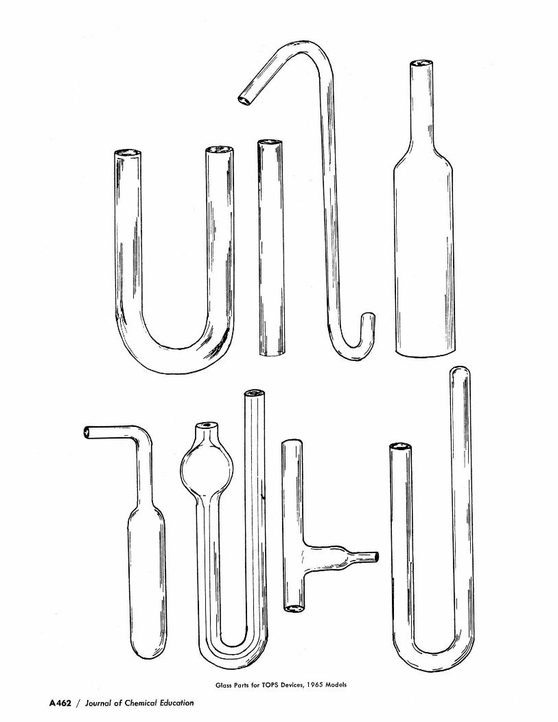
Glois Ports for TOPS Devices, 1965 Models
A462 / Journal of Chemical Education