development os shaker mohd hafiezal bin nordin …umpir.ump.edu.my/id/eprint/6523/1/cd7730.pdf ·...
TRANSCRIPT

DEVELOPMENT OS SHAKER
(CONTROLLER)
MOHD HAFIEZAL BIN NORDIN
Report submitted in fulfillment of the requirements for
the award of degree of Bachelor of Mechatronics Engineering
Faculty of Manufacturing Engineering
UNIVERSITI MALAYSIA PAHANG
JUNE 2013

vi
ABSTRACT
The automatic control has played a role in the advance of engineering and
science. Nowadays, the control of direct current (DC) motor is a common practice in
industry thus the implementation of DC motor of controller speed is important. The
main purpose of motor speed controller is to keep the rotation of the motor at the preset
speed and to drive a system at the demanded speed. When used in speed application,
speed feedback control the DC motor’s speed or confirms that the motor is rotating at
the desired speed. The speed of a DC motor usually is directly proportional to the supply
voltage. For instance, if we reduce the supply voltage from 12 Volts to 6 Volts the motor
will run at half or lower the speed. The advantages used DC motor is provide excellent
speed control for acceleration and deceleration with effective and simple torque control.
The fact that the power supply of a DC motor connects directly to the field of the motor
allows for precise voltage control, which is necessary with speed and torque control
applications. The common methods are used to control speed DC motor is Proportional
Integral Derivative (PID) and PC based to control it. In this project, the method use as
controller is using Arduino Uno as microcontroller for the electric current control to
drive a motor. The expectation of this project is to get the precise the demanded speed
and to drive a motor at that speed.

vii
ABSTRAK
Kawalan automatik telah memainkan peranan dalam kemajuan kejuruteraan dan
sains. Kini, kawalan arus terus (DC) motor adalah biasa
amalan dalam industri itu pelaksanaan DC motor pengawal kelajuan adalah penting.
Tujuan utama pengawal kelajuan motor adalah untuk memastikan putaran motor pada
kelajuan yang ditetapkan dan untuk memandu sistem pada kelajuan yang diminta.
Apabila digunakan dalam permohonan kelajuan, maklum balas kelajuan mengawal
kelajuan motor DC atau mengesahkan bahawa motor yang berputar pada kelajuan yang
dikehendaki. Kelajuan motor DC biasanya adalah berkadar terus dengan voltan bekalan.
Sebagai contoh, jika kita mengurangkan voltan bekalan dari 12 volt ke 6 volt motor akan
berjalan pada separuh atau lebih rendah kelajuan. Kelebihan digunakan DC motor
menyediakan kawalan kelajuan yang cemerlang untuk pecutan dan nyahpecutan dengan
kawalan tork berkesan dan mudah. Hakikat bahawa bekalan kuasa motor DC
menghubungkan terus kepada bidang motor membolehkan kawalan voltan yang tepat,
yang perlu dengan aplikasi kawalan kelajuan dan tork. Kaedah yang biasa digunakan
untuk mengawal kelajuan motor DC adalah derivatif Penting Berkadar (PID) dan
Komputer berasaskan untuk mengawalnya. Dalam projek ini, kaedah yang digunakan
sebagai pengawal menggunakan Arduino Uno sebagai pengawal micro untuk mengawal
arus elektrik untuk memandu motor. Jangkaan projek ini adalah untuk mendapatkan
tepat kelajuan yang diminta dan untuk memandu motor pada kelajuan itu.

viii
TABLE OF CONTENTS
SUPERVISOR’S DECLARATION ii
STUDENT’S DECLARATION iii
DEDICATION iv
ACKNOWLEDGEMENTS v
ABSTRACT vi
ABSTRAK vii
TABLE OF CONTENTS viii
LIST OF TABLES xii
LIST OF FIGURES xiii
LIST OF SYMBOLS xv
CHAPTER 1: INTRODUCTION
1.1 Project Background 1
1.2 Objectives of Project 3
1.3 Scope of the Project 3
1.4 Problem Statement 4
1.5 Thesis Outline 5

ix
CHAPTER 2 LITERATURE REVIEW
2.1 Introduction 6
2.2 DC Motor 7
2.3 Controller 9
2.4 Pulse Width Modulation 12
2.5 Speed Control DC Motor Using Microcontroller 14
2.6 Analog to Digital Converter 16
2.7 Model of Separately exited DC motor 18
2.8 Speed Measurement of DC Motor 21
2.8.1 Speed Measurement by Using Tachometer 21
2.9 Microcontroller 22
CHAPTER 3 METHODOLOGY
3.1 Introduction 24
3.2 Research Methodology 24
3.3 Hardware Implementation 26
3.3.1 Wire/ cable configuration 28
3.3.2 Connection L293D and Arduino 28
3.4 Software Development 29
3.5 Block Diagram 30
3.5.1 Analog to digital Converter 30

x
3.5.2 Pulse Width Modulation Technique 31
3.6 Motor Driver 32
3.7 Relationship between speed and frequency 33
3.8 Conclusion 34
CHAPTER 4 RESULTS AND DISCUSSION
4.1 Introduction 35
4.2 Result and Finding 35
4.2.1 Triangle wave 37
4.2.2 Pulse Width Modulation (Comparator) 38
4.2.3 PWM (Duty Cycle: 52%) 39
4.2.4 PWM (Duty Cycle:99%) 40
4.2.5 PWM (Duty Cycle:1%) 41
4.2.6 PWM (Duty Cycle 15%) 42
4.3 Conclusion 42
CHAPTER 5 CONCLUSION AND RECOMMENDATIONS
5.1 Introduction 43
5.2 Conclusion 43
5.3 Recommendation 44

xi
REFERENCES 45
APPENDICES
A Gantt Chart 47
B Coding AVR 49
C L293 Motor Driver Datasheet 51
D DC Motor 12 V SPG-30 Datasheet 60

1
CHAPTER 1
INTRODUCTION
1.1 Project Background
In many industries, a device that used in order to convert electrical energy into
mechanical energy is called as the direct current (DC) motor. All result is from the
availability of speed controllers which is wide range, easily and many ways. Speed
control is very important in most applications, which is for an example, if we have DC
motor in radio controller car, if we just apply a constant power to the motor, it is
impossible to maintain the desired speed. It will go slower over rocky road, slower
uphill, faster downhill and so on. It is important to make a controller to control the speed
of DC motor in desired speed. In modern industry, DC motor plays a significant role.
Speed control of dc motor could be achieved using mechanical or electrical
techniques. In the past, speed controls of dc drives are mostly mechanical. Requiring
large size hardware to implement. Advances in the area of power electronics have
brought a total revolution in the speed control of dc drives. This development has
launched these drives back to a position of formidable relevance, which were hitherto
predicted to give way to ac drives. These drives have now dominated the area of
variable speed because of their low cost, reliability and simple control.

2
To take a signal representing the demanded speed, and to drive a motor at that
speed is The purpose of a motor speed controller. There are numerous applications
where control of speed is required, as in rolling mills, cranes, hoists, elevators, machine
tools, transit system and locomotive drives. These applications may demand high-speed
control accuracy and good dynamic responses.
DC motor is widely used in metallurgy, machinery manufacturing and light
industry because of its good performance in starting and breaking and its easily
controlled speed regulation. In recent years, with the development of the power
electronic technology, the thyristor rectifier is commonly used for the power supply of
the DC motor, which replaces the AC motor—DC generator power supply system. But
DC motor speed control system is a complex multivariable nonlinear control system,
because the various parameters influence each other, it’s anti—interference ability is
weak and it’s not suitable for high control performance occasion.
Therefore, in order to enhance DC motor speed control system of anti—jamming
and robustness, and improve the response speed and stable precision of the speed
regulation system, this paper discuss the PWM DC motor speed control system based on
the fuzzy control and neural network control.
In conclusion, in devices ranging from toys, house appliance and robotics to
industrial application, the simplicity of control speed made DC motors to be common.

3
1.2 Objective of the Project
Basically, these projects are having three main objectives. The objectives are a
guideline and goal in order to complete this project. This project is conducted to achieve
the following objectives:
I. To develop controller using microcontroller as programming.
II. To design the hardware of the controller to control DC motor
frequency.
III. To develop precisely control the DC motor.
1.3 Scope of the Project
There are two scopes in this project which is hardware development and
software development. For the first scope which is hardware development there are
three main section. First are to design a circuit that can integrate with MicroController,
nest is to design a circuit for control speed of DC motor, and lastly for to design a circuit
for the motor driver.
While For the second scope which is the software development, there are two
main sections and that section are. Firstly try to simulate the control system using
Multisim software, next develop a software or coding and integrate with Arduino uno.

4
1.4 Problem Statement
The efficiency and reliability are the most issue discusses in speed controller. In
order to save cost, the efficiency element is important. The efficiency of speed controller
is depending on method control system. The speed controller usually controls in analog
system and an analog signal has a continuously varying value, with infinite resolution in
both time and magnitude. For example, a 10 V is an analog and its output voltage is not
precisely 10 V, changes over time, and can take any real-numbered value.
Similarly, the amount current drawn from a battery is not limited to a finite set of
possible value. Analog signals are distinguishable from digital signals because the latter
away take values only from a finite set of predetermined possibilities. DC motor widely
used in speed control systems which needs high control requirement such as rolling mill,
double-hulled tanker and high precision digital tools. So, it is crucial to control the
motor speed in order to achieve good production.
One of the most common methods to drive a DC motor is by using PWM signals
respect to the motor input voltage. Manual controller is also not practical in the
technology era because it can waste time and cost. Operation cost regarding controller is
got attention from industrial field. In order to reduce cost and time, we suggest making a
controller based on computer because it is portable. The user can monitor their system at
certain place without need to going to the plant (machine) especially in industrial
implementation. From that, the man power can be reduced and reserve with computer
which is more precise and reliable. The other product regarding this project where
control motor via computer may be commercialized but their cost is very expensive. The
hardware of this product may be complicated and maintenance cost is higher. The low
cost electronic devices can be designed to make a speed controller system. So this thesis
will select PWM to control the speed of DC Motor using witdh modulation

5
1.5 Thesis Outline
Chapter one, it discusses about introduction and overview about this project
includes background, objectives and scope of projects.
Chapter two is explanations about literature review as study material and
references. The topics that I have studied are about the other method of speed control to
compare and analysis their advantages and disadvantages. From the literature review,
knowledge can be gained thus implement in this project.
On chapter three, the methodology that I have done are discusses. This is
explanations about the method used to complete hardware and software.
Chapter four are discusses of the result and analysis of this project. In this
chapter also will explain how PWM is produce and how its control the speed of the DC
motor.
Chapter five are describes conclusion and future recommendation to make this
project greatly.
This thesis included with references and appendices. Also refer the further
information about this project in references which is states the source and their authors.
Datasheet of the components, photo and other information also placed on the appendices
part.

6
CHAPTER 2
LITERATURE REVIEW
2.1 Introduction
Although a far greater percentage of electric motors in service are a.c. motors, the
d.c. motor is of considerable industrial importance. Its speed can be changed over a wide
range by a variety of simple methods is the principal advantage of a d.c. motor. With a.c
motors, such a fine speed control is generally not possible. In fact, fine speed control is
one of the reasons for the strong competitive position of d.c. motors in the modem
industrial applications. In this chapter, we shall discuss the various methods of-speed
control of d.c. motors.
7
2.2 DC Motor
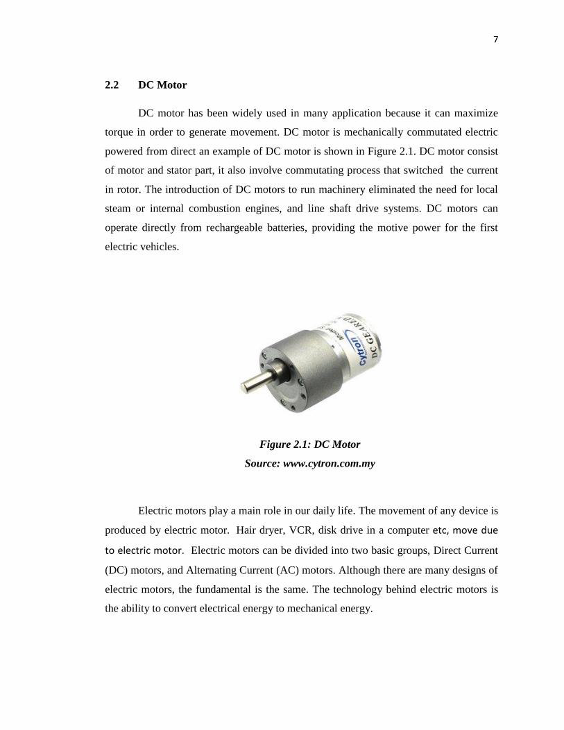
DC motor has been widely used in many application because it can maximize
torque in order to generate movement. DC motor is mechanically commutated electric
powered from direct an example of DC motor is shown in Figure 2.1. DC motor consist
of motor and stator part, it also involve commutating process that switched the current
in rotor. The introduction of DC motors to run machinery eliminated the need for local
steam or internal combustion engines, and line shaft drive systems. DC motors can
operate directly from rechargeable batteries, providing the motive power for the first
electric vehicles.
Figure 2.1: DC Motor
Source: www.cytron.com.my
Electric motors play a main role in our daily life. The movement of any device is
produced by electric motor. Hair dryer, VCR, disk drive in a computer etc, move due
to electric motor. Electric motors can be divided into two basic groups, Direct Current
(DC) motors, and Alternating Current (AC) motors. Although there are many designs of
electric motors, the fundamental is the same. The technology behind electric motors is
the ability to convert electrical energy to mechanical energy.

8
A DC motor is a mechanically commutated electric motor powered from direct
current (DC). The stator is stationary in space by definition and therefore its current.
The current in the rotor is switched by the commutator to also be stationary in space.
This is how the relative angle between the stator and rotor magnetic flux is maintained
near 90 degrees, which generates the maximum torque.
The printed circuit board (PCB) motor, using permanent magnet, has a
configuration radically different from that of the conventional DC motor. The entire
armature winding and the commutator are printed in PCB disk (rotor). This type of
motor has several advantages such as high torque that allows it provides rapid
acceleration and deceleration. The motor can accelerate from 0 to 4000 rpm in 10
milliseconds. The motor has no cogging torque because the rotor is nonmagnetic.
These motors are particularly suitable for applications requiring high
performance characteristics. There are other types of DC motor that have their own
advantages and disadvantages. The variety of DC motor types give a variety of control
method and also the variety of application that can be performed. In conclusion, DC
motors have many types and differ with each other in characteristics of the motor and
also the use the motor in appliances. There are several types of DC motors that are
available. Their advantages, disadvantages and other basic information are list below in
the table below.

9
Table 2.1: Advantages and Disadvantages of various type DC Motor
TYPE ADVANTAGES DISADVANTAGE
Stepper Motor Very precise speed and
position control.
High torque at low speed.
Expensive and hard to find.
Required a switching
control circuit.
DC Permanent Magnet
Motor
Small.
Compact
Easy to find
Very inexpensive
Generally small.
Cannot vary magnetic field
strength.
DC Motor W/field coil Wide range of speed and
torque.
More powerful than
permanent magnet motors.
Require more current than
permanent magnet motors,
since field coil, must be
energized.
Generally heavier than
permanent magnet motors.
More difficult to obtain.
2.3 Controller
Controller is a chip, an expansion card or a stand-alone device that interfaces with a
peripheral devices. This may be a link between two part of a computer for example a
memory controller or a controller on an external device that mange the operation of the
device. Most microcontrollers at this time had two variants. One had an
erasable EPROM program memory, with a transparent quartz window in the lid of the
package to allow it to be erased by exposure to ultraviolet light. The other was

10
a PROM variant which was only programmable once; sometimes this was signified with
the designation OTP, standing for "one-time programmable".
The PROM was actually exactly the same type of memory as the EPROM, but
because there was no way to expose it to ultraviolet light, it could not be erased. The
erasable versions required ceramic packages with quartz windows, making them
significantly more expensive than the OTP versions, which could be made in lower-cost
opaque plastic packages. For the erasable variants, quartz was required, instead of less
expensive glass, for its transparency to ultraviolet glass is largely opaque to UV but the
main cost differentiator was the ceramic package itself.
The use of micro controller for speed control and protection of dc motor is presented
in this paper. The peculiarity of this method is its adaptability to different ratings of
motors. By using mechanical or electrical techniques, speed control of dc motor could
be achieved. The speed controls of dc drives are mostly mechanical in the past and
requiring large size hardware to implement. Advances in the area of power electronics
have brought a total revolution in the speed control of dc drives.
This development has launched these drives back to a position of formidable
relevance, which were hitherto predicted to give way to ac drives. These drives have
now dominated the area of variable speed because of their low cost, reliability and
simple control. DC drives are widely used in applications requiring adjustable speed;
good speed regulation and frequent starting, braking and reversing. Some important
applications are: rolling mills, paper mills mine winders, hoists, machine tools, traction,
printing presses, textile mills, excavators and cranes. Fractional horsepower dc drives
are widely employed -as servo means for positioning and tracking. [1]
By controlling armature or field excitation, adjustable speed drives may be operated
over a wide range. Speeds below rated by armature voltage control and above rated
using field excitation variation, development of various solid sates switching devices in
the form of diodes, transistor and thyristor along with various analog digital chips used

11
in firing controlling circuits, have made dc Drives more accessible for control in
innumerable areas of applications. [2]
Every electric motor has to have some sort of controller. The motor controller will
have differing features and complexity depending on the task that the motor will be
performing. The simplest case is a switch to connect a motor to a power source, such as
in small appliances or power tools. The switch may be manually operated or may be a
relay or contactor connected to some form of sensor to automatically start and stop the
motor. The switch may have several positions to select different connections of the
motor. This may allow reduced-voltage starting of the motor, reversing control or
selection of multiple speeds.
Overload and over current protection may be omitted in very small motor
controllers, which rely on the supplying circuit to have over current protection. Small
motors may have built-in overload devices to automatically open the circuit on overload.
Larger motors have a protective overload relay or temperature sensing relay included in
the controller and fuses or circuit breakers for over current protection. An automatic
motor controller may also include limit switches or other devices to protect the driven
machinery. A motor controller is a device or group of devices that serves to govern in
some predetermined manner the performance of an electric motor.[3]
More complex motor controllers may be used to accurately control the speed and
torque of the connected motor (or motors) and may be part of closed loop control
systems for precise positioning of a driven machine. For example, a numerically
controlled lathe will accurately position the cutting tool according to a preprogrammed
profile and compensate for varying load conditions and perturbing forces to maintain
tool position. A motor controller might include a manual or automatic means for starting
and stopping the motor, selecting forward or reverse rotation, selecting and regulating
the speed, regulating or limiting the torque, and protecting against overloads and faults.
[4]

12
2.4 Pulse Width Modulation
Figure 2.2: Pulse Width Modulation Signal
Source: www.wikipedia.org
Pulse-width modulation (PWM), or pulse-duration modulation (PDM), is a
modulation technique that conforms the width of the pulse, formally the pulse duration,
based on modulator signal information. Although this modulation technique can be used
to encode information for transmission, its main use is to allow the control of the power
supplied to electrical devices, especially to inertial loads such as motors.The use of
stand-alone micro controller for the speed control of DC motor is past gaining ground.
Nicolai and Castagnct have shown in their paper how a micro controller can be used for
speed control. The operation of the system can be summarized as: the drive form a
rectified voltage, it consists of chopper driven by a PWM signal generated from a micro
controller unit (MCU). The motor voltage control is achieved by measuring the rectified
mains voltage with the analog to-digital converter present on the micro controller and
adjusting the PWM signal duty cycle accordingly. [5]

13
The term duty cycle describes the proportion of 'on' time to the regular interval or
'period' of time; a low duty cycle corresponds to low power, because the power is off for
most of the time. Duty cycle is expressed in percent, 100% being fully on. The main
advantage of PWM is that power loss in the switching devices is very low. When a
switch is off there is practically no current, and when it is on, there is almost no voltage
drop across the switch. Power loss, being the product of voltage and current, is thus in
both cases close to zero. In the past, when only partial power was needed (such as for a
sewing machine motor), a rheostat (located in the sewing machine's foot pedal)
connected in series with the motor adjusted the amount of current flowing through the
motor, but also wasted power as heat in the resistor element. It was an inefficient
scheme, but tolerable because the total power was low. This was one of several methods
of controlling power.
There were others—some still in use—such as variable autotransformers,
including the trademarked 'Autrastat' for theatrical lighting; and the Variac, for general
AC power adjustment. These were quite efficient, but also relatively costly. PWM can
be used to control the amount of power delivered to a load without incurring the losses
that would result from linear power delivery by resistive means.
Potential drawbacks to this technique are the pulsations defined by the duty
cycle, switching frequency and properties of the load. With a sufficiently high switching
frequency and, when necessary, using additional passive electronic filters, the pulse
train can be smoothed and average analog waveform recovered.High frequency PWM
power control systems are easily realisable with semiconductor switches. As explained
above, almost no power is dissipated by the switch in either on or off state. However,
during the transitions between on and off states, both voltage and current are nonzero
and thus power is dissipated in the switches. By quickly changing the state between
fully on and fully off (typically less than 100 nanoseconds), the power dissipation in the
switches can be quite low compared to the power being delivered to the load.

14
For about a century, some variable-speed electric motors have had decent
efficiency, but they were somewhat more complex than constant-speed motors, and
sometimes required bulky external electrical apparatus, such as a bank of variable power
resistors or rotating converter such as Ward Leonard drive. However, in addition to
motor drives for fans, pumps and robotic servos, there was a great need for compact and
low cost means for applying adjustable power for many devices, such as electric stoves
and lamp dimmers. One early application of PWM was in the Sinclair X10, a 10 W
audio amplifier available in kit form in the 1960s. At around the same time PWM
started to be used in AC motor control. [6]
2.5 Speed Control DC Motor Using Microcontroller
Now a days, automatic control systems are used widely to minimize the human
errors and increase the production rate with good quality. So most of the machines used
in production stream uses induction motors with variable speeds. Using analog methods
we can vary the speed, but they are not accurate because of the tolerance of the devices,
and also the circuit is complex.
There is a lot of method in controlling DC motor speed, for example Multiple
Voltage Control and Ward-Leonard System. In Multiple voltage control method, , the
shunt field of the motor is connected permanently to a fixed exciting voltage, but the
armature is supplied with different voltages by connecting it across one of the several
different voltages by means of suitable switchgear. The armature speed will be
approximately proportional to these different voltages. The intermediate speeds can be
obtained by adjusting the shunt field regulator.
On the other hands, Ward-Leonard System is used where an unusually wide and
very sensitive speed control is required as for colliery winders, electric excavators,
elevators and the main drives in steel mills and blooming and paper mills. M1 is the
main motor whose speed control is required. The field of this motor is permanently

15
connected across the dc supply lines. By applying a variable voltage across its armature,
any desired speed can be obtained. This variable voltage is supplied by a motor-
generator set which consists of either a dc or an ac motor M2directly coupled to
generator G. The motor M2 runs at an approximately constant speed. The output voltage
of G is directly fed to the main motorM1. The voltage of the generator can be varied
from zero up to its maximum value by means of its field regulator. By reversing the
direction of the field current of G by means of the reversing switch RS, generated
voltage can be reversed and hence the direction of rotation of M1. It should be
remembered that motor generator set always runs in the same direction
Figure 2.3: Arduino Uno
Source: www.arduino.cc
In order to meet higher performance and reliability requirements, the electric
drive systems used in industrial applications are increasingly. The DC motor is an
attractive place of equipment in many industrial applications requiring variable speed
and load characteristics due to its ease of controllability. Microcontrollers provide a
suitable means of meeting these needs. Certainly, part of the recent activity on
microcontrollers can be ascribed to their newness and challenge. In this project use
microcontroller as controller for the speed controller use PIC.

16
Another system that uses a microprocessor is reported in the work is reported in
journal a brief description the system is as follow: The microprocessor computes the
actual speed of the motor by sensing the terminal voltage and the current, it then
compares the actual speed of the motor with the reference speed and generates a suitable
control signal which is fed into triggering unit.
A simple form of speed control is achieved through a variable potentiometer for a
manually controlled system; the operator mentally compares the actual speed to a
desired speed and sets the potentiometer accordingly. A simple form of speed control is
achieved through a variable potentiometer for a manually controlled system; the
operator mentally compares the actual speed to a desired speed and sets the
potentiometer accordingly. Updated on the CRT screen each second to a desired speed,
he/she corrects the current speed by rotating the potentiometer clockwise to increase or
counterclockwise to reduce the speed, by comparing the speed in revolution per seconds
(rps). [7]
2.6 Analog to Digital Converter
An analog-to-digital converter (abbreviated ADC, A/D or A to D) is a device that
converts a continuous physical quantity (usually voltage) to a digital number that
represents the quantity's amplitude. The conversion involves quantization of the input,
so it necessarily introduces a small amount of error. The inverse operation is performed
by a digital-to-analog converter (DAC). Instead of doing a single conversion, an ADC
often performs the conversions ("samples" the input) periodically. The result is a
sequence of digital values that have converted a continuous-time and continuous-
amplitude analog signal to a discrete-time and discrete-amplitude digital signal.
An ADC is defined by its bandwidth (the range of frequencies it can measure) and its
signal to noise ratio (how accurately it can measure a signal relative to the noise it

17
introduces). The actual bandwidth of an ADC is characterized primarily by its sampling
rate, and to a lesser extent by how it handles errors such as aliasing. The dynamic range
of an ADC is influenced by many factors, including the resolution (the number of output
levels it can quantize a signal to), linearity and accuracy (how well the quantization
levels match the true analog signal) and jitter (small timing errors that introduce
additional noise). The dynamic range of an ADC is often summarized in terms of
its effective number of bits (ENOB), the number of bits of each measure it returns that
are on average not noise. An ideal ADC has an ENOB equal to its resolution. ADCs are
chosen to match the bandwidth and required signal to noise ratio of the signal to be
quantized. If an ADC operates at a sampling rate greater than twice the bandwidth of the
signal, then reconstructions possible given an ideal ADC and neglecting quantization
error. The presence of quantization error limits the dynamic range of even an ideal
ADC, however, if the dynamic range of the ADC exceeds that of the input signal, its
effects may be neglected resulting in an essentially perfect digital representation of the
input signal.
Recently, a fully digital approach to generate a test stimulus by PWM used for high
resolution ADCs has been reported with a focus on static test [8]. The advantage of this
technique is that a 1-bit data pulse train can convey the wanted test signal without
harmonic distortions that is particularly attractive for on-chip test. This is in contrast to
the true analog techniques or DA conversion based techniques implemented on a chip,
where the spectral purity of the generated signals can be difficult to guarantee.
The other technique, i.e. uniform-PWM is relatively simpler to implement digitally
but suffers from harmonic distortion components of the modulating signal. Different
algorithmic approaches have been reported to reduce the harmonic content and improve
SNR, including enhanced sampling process [9]