development of very-high-strength and high-performance
TRANSCRIPT

DEVELOPMENT OF VERY-HIGH-STRENGTH AND HIGH-PERFORMANCE CONCRETE MATERIALS FOR IMPROVEMENT OF BARRIERS
AGAINST BLAST AND PROJECTILE PENETRATION
E. F. O’Neil III*, T. K. Cummins, B.P. Durst, P. G. Kinnebrew and R. N. Boone U.S. Army Engineer Research and Development Center
Vicksburg, MS, 39180
R. X. Torres University of Puerto Rico, Mayaguez
Mayaguez, PR, 00681
ABSTRACT
The U.S. Department of Defense is constantly
pursuing new technologies to improve the capabilities of protective structures in defeating current and emerging threats thus providing a safer environment in which its soldiers must work and fight. Exploiting innovative uses of cement-based materials, the U. S. Army Engineer Research and Development Center (ERDC) is developing several high-performance concretes to mitigate the effects of blast and ballistic threats from conventional and asymmetric weapons. This paper presents the theory, development, and preliminary laboratory and field experimental results of two distinctly different classes of high-performance concretes.
The first material presented in this paper is a very-
high-strength concrete engineered for low-cost structural armoring applications. Innovative application of particle selection and distribution, advanced fiber selection in multiple magnitudes of scale, and modified curing techniques are being developed to increase the strength and toughness of this high-performance composite beyond current state-of-the-art performance.
At the other end of the performance envelope, this
paper discusses the development of a material with an innovative combination of mechanical properties that are engineered for mitigation of debris hazards generated by high intensity blast loadings. This material shows great promise for construction applications for barricades and non-load-bearing walls where improvised explosive devices could be employed to inflict human casualties.
1. INTRODUCTION
ERDC, under its Survivability and Protective Structures (S&PS) research thrust, is currently evaluating a variety of high performance concretes for use in force protection applications. Today’s warfighter faces an increasing likelihood of both conventional and
asymmetric/terrorist attacks. Adversaries will exploit strike opportunities against Future Force soldiers and high value assets across the battlespace. Severe logistical constraints of the present and future Army require high-performance protective materials/systems to be lightweight, low bulk, cost effective, and operationally compatible. These problems related to Future Force survivability require innovative passive defense solutions for mitigation of potential weapon threats. High-performance concrete materials are playing a major role in achieving these goals.
The Concrete and Materials Branch (CMB) of the
Geotechnical and Structures Laboratory (GSL), ERDC has developed a very high strength concrete (VHSC) with superior properties of strength and toughness. Its compressive strength is on the order of 5 times greater than conventional high-strength concrete and its toughness is well over 8 times greater than that of conventional fiber-reinforced concrete. The Survivability Engineering Branch (SvEB), GSL, ERDC is using this concrete material in a low-cost, high performance armor component of a modular, man-portable light-weight, protective system currently under development. This system is being designed to focus on defeat of the blast and ballistic effects from direct and indirect fire threats.
VHSC uses dense particle packing technology and
selective material components to enhance the strength of the concrete as well as the inclusion of high performance fibers to bridge cracks and consume energy during the fracture process, thereby toughening the material. This paper will explain the principles used to make VHSC, describe its contribution to the composite armor paneling, and present the results of the micro-fiber toughening research currently being conducted at ERDC.
The term high-performance in concrete materials is generally associated with high strength, but in reality the term refers to an enhanced level of performance of any desired property of the concrete material. For instance, a low-strength concrete that provides enhanced properties
1

Report Documentation Page Form ApprovedOMB No. 0704-0188
Public reporting burden for the collection of information is estimated to average 1 hour per response, including the time for reviewing instructions, searching existing data sources, gathering andmaintaining the data needed, and completing and reviewing the collection of information. Send comments regarding this burden estimate or any other aspect of this collection of information,including suggestions for reducing this burden, to Washington Headquarters Services, Directorate for Information Operations and Reports, 1215 Jefferson Davis Highway, Suite 1204, ArlingtonVA 22202-4302. Respondents should be aware that notwithstanding any other provision of law, no person shall be subject to a penalty for failing to comply with a collection of information if itdoes not display a currently valid OMB control number.
1. REPORT DATE 00 DEC 2004
2. REPORT TYPE N/A
3. DATES COVERED -
4. TITLE AND SUBTITLE Development Of Very-High-Strength And High-Performance ConcreteMaterials For Improvement Of Barriers Against Blast And ProjectilePenetration
5a. CONTRACT NUMBER
5b. GRANT NUMBER
5c. PROGRAM ELEMENT NUMBER
6. AUTHOR(S) 5d. PROJECT NUMBER
5e. TASK NUMBER
5f. WORK UNIT NUMBER
7. PERFORMING ORGANIZATION NAME(S) AND ADDRESS(ES) U.S. Army Engineer Research and Development Center Vicksburg, MS,39180; University of Puerto Rico, Mayaguez Mayaguez, PR, 00681
8. PERFORMING ORGANIZATIONREPORT NUMBER
9. SPONSORING/MONITORING AGENCY NAME(S) AND ADDRESS(ES) 10. SPONSOR/MONITOR’S ACRONYM(S)
11. SPONSOR/MONITOR’S REPORT NUMBER(S)
12. DISTRIBUTION/AVAILABILITY STATEMENT Approved for public release, distribution unlimited
13. SUPPLEMENTARY NOTES See also ADM001736, Proceedings for the Army Science Conference (24th) Held on 29 November - 2December 2005 in Orlando, Florida. , The original document contains color images.
14. ABSTRACT
15. SUBJECT TERMS
16. SECURITY CLASSIFICATION OF: 17. LIMITATION OF ABSTRACT
UU
18. NUMBEROF PAGES
17
19a. NAME OFRESPONSIBLE PERSON
a. REPORT unclassified
b. ABSTRACT unclassified
c. THIS PAGE unclassified
Standard Form 298 (Rev. 8-98) Prescribed by ANSI Std Z39-18
3. BASIS OF VHSC of frangibility can be considered to be high-performance concrete even though it doesn’t possess high strength. Such is the case with Safety Concrete. Under conditions such as the blast loading from a Vehicle Borne Improvised Explosive Device (VBIED) on a barrier made of concrete blocks, the blocks will break into fragments and be propelled at high velocity. These fragments can be small, or as large as an entire block. At velocities of several hundred feet per second, they become hazardous projectiles that can maim and kill. The CMB and the SvEB are working together with Northwestern University to develop a concrete block that will fracture into small pieces under blast-induced loads and not become a lethal hazard. The frangibility of these blocks is likened to the fracture of automotive safety glass and hence has been named Safety Concrete. The material technology to produce it involves use of alternative cementitious materials and specialized curing conditions. This paper will discuss the theory of the material’s frangibility, the materials studied under a laboratory experimental matrix, and the preliminary results from a recent field experiment.
There are a number of strategies that are important to
the engineering of high strength and low porosity of VHSC. First and foremost, it is critical to avoid including flaws in the matrix. Flaws can be caused by any condition that disrupts the homogeneity of the matrix, such as capillary pores, entrained or entrapped air bubbles, or poor quality paste at the paste/aggregate interface. These flaws are initiation sites for the development and growth of microcracks. Flaws act as stress concentrators, multiplying the stress at the flaw many times higher than that of the applied stress. As load is applied to the cement matrix, the localized stress at the flaw exceeds the tensile strength of the paste, which initiates a microcrack. As the applied stress increases, the microcracks grow into mesocracks, the mesocracks coalesce into macrocracks, and the concrete fails. By engineering the volumes and composition of component materials in VHSC, flaws are minimized and the cement paste can carry a higher level of load before microcracks begin to form, thus an inherently higher load-carrying capacity can be realized before failure.
2. VHSC BACKGROUND Particle packing theory is used to minimize sites for
flaws and maximize solid material volume in VHSC. The theory is to choose the volume of a material to fit in the void space formed by the next larger sized particle. Sand is the largest size material used in VHSC. Its maximum particle diameter is less than 9 mm and ranges down to the 500 µm range. Cement is the next largest particle ranging from 10 to 100 µm. Silica flour, which is finely ground quartz, is also used as an aggregate to increase the volume of silica. Its particle diameters range from 1 – 10 µm. The smallest solid particle used is silica fume. It plays a very important role in the hydration process and is used in quantities that are much higher than in normal concrete mixtures. Silica fume has a particle diameter in the range of 0.1 – 1 µm. Each of the successively smaller sized particles will pack into the void space between the larger particles and fill voids that would otherwise be flaws.
In conventional construction practice, concrete is
proportioned to minimize cost, provide for adequate workability, and achieve adequate strength. These properties are often achieved by minimizing the volume of cement used, maximizing the volume of aggregate, and adding water until the mixture is easy to place.
These conventional practices generally yield concrete
with compressive strengths ranging from around 3000 to 5000 psi. Their strength is limited by flaws in the cement paste matrix brought on by excess water and the use of cementitious materials not optimized for producing maximum strength. Judicious choice of component materials and the proper engineering of their volumes can produce very high strength concrete using conventional concreting materials.
The CMB, GSL has been involved in the
development of very-high-strength and high performance concrete materials for the last decade. In cooperation with engineers and scientists of the SvEB, and guided by goals of improving barriers to blast and projectile penetration resistance, this team has developed a high performance concrete material, called VHSC, that is proportioned to optimize strength and toughness by minimizing the conditions that produce premature failure in the matrix.
Improved material homogeneity also strengthens the
matrix. Since calcium silicate hydrate (C-S-H) is the main hydration product in cement paste, it is beneficial that the paste components be composed of as much silica based material as possible to maximize creation of C-S-H. Choosing a cement with a high silica content and incorporating silica flour, silica fume, and silica sand into the mixture maximizes the silica volume and minimizes differential strain under stress from component materials with different moduli of elasticity. This reduces stress and further delays the onset of micro-fractures.
The use of high percentages of silica fume plays an
important role in the development of high strength. The
2
silica fume strengthens the matrix in two ways. Firstly, its small size allows millions of the particles to occupy the void space formed when the larger cement particles come in contact. Otherwise, this space would be filled with weak, high water-to-cement ratio C-S-H and become a site for early formation of microcracks. Secondly, silica fume creates more C-S-H while consuming a detrimental by-product. When portland cement combines with water, the products formed are C-S-H and calcium hydroxide (CH). The C-S-H is strong, but the CH forms crystalline material with one weak plane that has a tendency to cleave under stress. Silica fume in the mixture combines with water and the unwanted CH to form additional C-S-H, thereby consuming a weak hydration product and producing a stronger component.
Additional strength in VHSC is achieved by using
very low water-to-cement ratios. Neville (1996) calculated the ratio of water to cement (w/c) necessary to consume all the water and create C-S-H was 0.42. At higher w/c, excess water remains in the paste to form capillary channels (a source of flaws). At lower w/c, not all the cement would hydrate but would remain as unhydrated clinker. In mixtures with a w/c greater than 0.42, the strength decreases with increase in w/c. In mixtures with w/c less than 0.42 the strength increases with the decrease in w/c down to a ratio of about 0.20 where there is not enough water for hydration. VHSC uses a w/c of 0.25 to achieve the highest level of strength and still be mixeable.
Low w/c mixtures are stiff and unworkable. The use
of high-range water-reducing admixtures (HRWRAs) alleviates stiffness and limited workability by assisting in deflocculating the cement grains. Cement has a tendency to floc together, making it difficult for water to get to the free surface of the cement grains. HRWRAs deposit a negative charge on the cement grain, causing the grains to repel each other, allowing the limited volume of water to coat the grains. This has the effect of increasing the workability and enhancing hydration without adding strength-robbing water.
Additional strength improvement can be realized by
curing the VHSC at elevated temperatures. By curing the VHSC at 90° C, a chemical phase change occurs and the amorphous, glassy C-S-H is converted to tobermorite, a higher strength ordered crystalline structure. The crystalline nature of the tobermorite enhances the strength of the structure over the lower strength amorphous C-S-H, but at the price of greater brittleness. A brittle material under load will store strain energy to a point and then fail very rapidly with no additional capacity to deform while carrying load. A good example is the breaking of a glass rod under a bending load. The glass lacks ductility or the ability to carry load in the post-peak-load regime. Ductility is important in engineering materials because it
increases their toughness or energy consuming potential. Toughness is engineered into VHSC by incorporating discrete steel fibers into the cement matrix. After the brittle cement matrix fractures, additional energy must be consumed to pull the fibers out of the fractured paste for the crack to continue to open. This additional energy consumption enhances toughness. A good example of the benefits of toughness in military armor materials is the enhanced projectile stopping power of a toughened material.
4. RECENT VHSC DEVELOPMENT
The basis for engineering VHSC presented in the previous section has yielded concrete compressive strength on the order of 29,000 psi and eight-fold toughness increases over conventional fiber reinforced concrete. The strength and toughness of VHSC has allowed it to be a component of composite armor that can compete with more sophisticated ceramic armors at a fraction of the cost. This successful use of the material has driven efforts to further enhance its strength and toughness. Two areas that hold promise for increased performance of VHSC are use of more efficient HRWRAs and the development of microfiber technology to address delay of microcrack formation.
Recent developments in HRWRA chemistry have
improved the ability of these chemicals to deflocculate cement. The new generation of polycarboxylate based HRWRAs has increased the charge carrying capacity over the existing lignosulphonate based chemicals. In order to explore the added benefit of the new HRWRAs, a series of mixtures of VHSC were made changing only the HRWRA used in the mixture. The mixtures were made without steel fibers to evaluate both strength and flow characteristics. Four brands of HRWRA were evaluated, identified as A through D. Mixtures were made with the manufacturers’ recommended low and high HRWRA dosages listed in Table 1. Flow table tests were conducted on the fresh concrete and 2 in. cubes were cast for compressive strength. Compressive strength cubes were tested at 7- and 28-day ages and under high temperature curing.
Table 1. Dosages of HRWRA Studied Brand Dosages studied, ml/kg
A 3.9, 9.1 B 6.8, 13.3 C 5.2, 7.2 D 6.8, 9.7
The results of the flow and strength tests with polycarboxylate HRWRAs are presented in Table 2. Flow numbers are a function of the diameter of a sample
3

after it has spread from being dropped and impacted 25 times on a cam table. A number of 8 is very stiff while a number of 160 is very flowable. The manufacturers’ low-end doses produced moderately stiff mixtures while the upper end produced reasonably good flow.
Table 2. Flow and Strength Results from Polycarboxylate HRWRAs
Strength, psi Brand Dose, Ml/kg Flow 7d 28d Heat
3.9 29.8 19,880 21,786 30,833 A 9.1 102.8 18,027 21,729 20,991 6.8 56 20,316 26,008 35,151 B 13.3 128.9 18,975 24,423 32,765 5.2 61.8 19,844 25,751 34,433 C 7.2 122.1 20,052 23,961 35,778 6.8 61 19,229 19,782 34,752 D 9.7 112.2 19,626 21,645 30,568
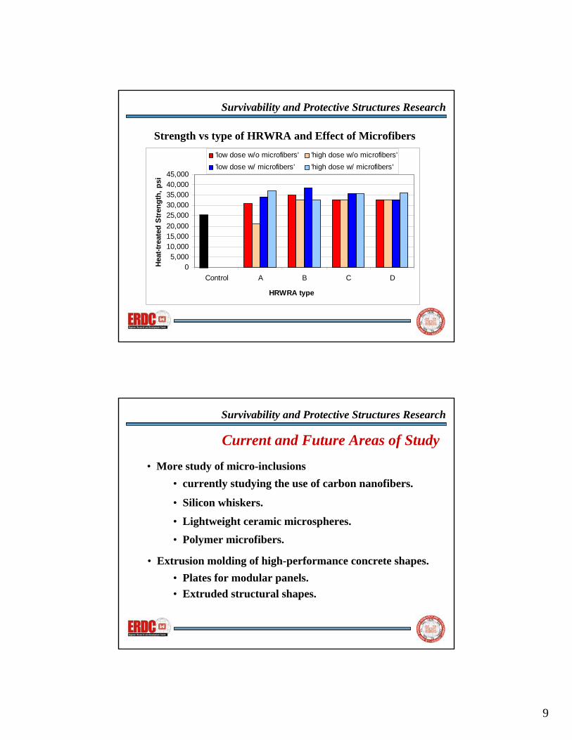
The results of the strength tests were very good. Prior to introduction of the new HRWRAs, the 28-day, non-heat-cured compressive strength of VHSC was about 15,000 psi. The 7-day strengths using the new HRWRAs ranged from 120 to 135 percent of this figure and the 28-day strengths ranged from 132 to 173 percent of this figure. With the old lignosulfonate HRWRA, the heat-cured strengths were about 29,000 psi. The heat-cured strength using the new HRWRAs ranged from 72 to 123 percent of this figure with brand C performing best. It appears that the dosage of HRWRA is not a factor in the resulting strength, only its presence in the mixture. For this reason, levels of HRWRA should be chosen based on desired flow characteristics.
5. MICROFIBER ENHANCEMENT STUDIES
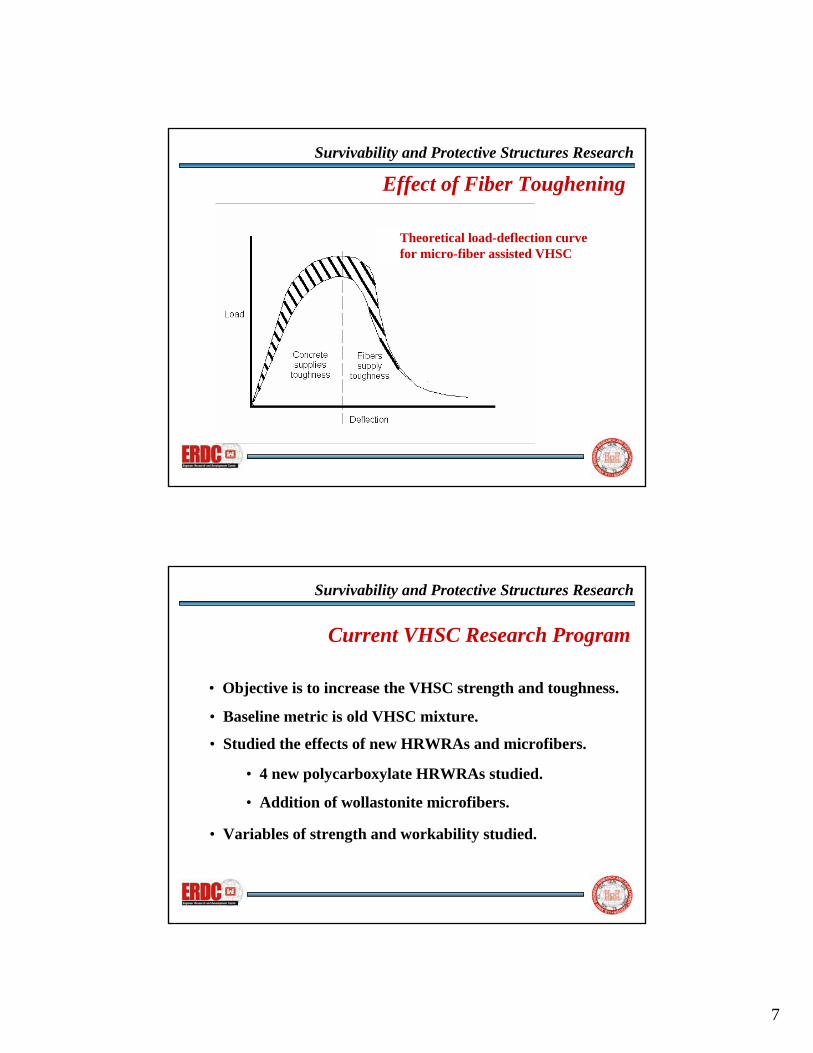
The vast majority of research into toughening brittle concrete materials has concentrated on macrofibers. These fibers enhance the toughness of the concrete in the post-peak, strain-softening region of the load-deflection curve after the concrete has failed and the fibers are the only mechanism left to consume additional energy. Very little research has been devoted to augmenting the toughness of the concrete in the pre-peak region of the load-deflection curve where the concrete is still contributing to the strength of the structure. In the lower half of the rising portion of the load-deflection curve, the strain is proportional to the stress and the concrete is acting nearly linearly elastic in nature. In the upper half of the pre-peak portion of the load-deflection curve, where the stress-strain relationship is no longer linear, the curvilinear nature of the stress-strain relationship is a function of the microcracking occuring in the matrix. The failure process starts with the microcracks beginning to grow and coalescing with other microcracks to form larger mesocracks. As the loading stress nears the failure
load, the mesocracks further grow together into macrocracks and the concrete matrix ultimately fails.
It is in this upper region of the pre-peak stress-strain
curve where it is believed that microfibers can augment the strength of the concrete in the same way that macrofibers enhance the toughness in the post-peak region of the curve. If enough microfibers (defined as fibers in the range of 50 to 200 µm in length) can be distributed into the cement paste matrix to cross any growing microcrack, then additional energy must be consumed in breaking the fiber or pulling it from the walls of the microcrack before the microcrack can grow. This additional energy manifests itself in higher failure loads in the concrete and additional toughness to the concrete.
An additional series of VHSC mixtures was made by
adding wollastonite microfibers to the basic VHSC mixture. The wollastonite fiber is a silica-based microfiber of approximately 50 to 100 µm in length. The flow and strength results are shown in Table 3 and a scanning electron microscope micrograph of the fibers is shown in Figure 1.
Table 3. Flow and Strength Results from Polycarboxylate HRWRAs with Microfibers
Strength, psi Brand Dose, Ml/kg Flow 7d 28d Heat
6.5 28.9 20,507 29,085 34,185 A 9.1 47.5 19,641 25,595 37,064 8.5 48.9 22,305 25,827 38,720 B 13.3 82.3 20,242 22,823 32,636 5.9 27.5 21,783 23,825 35,825 C 7.2 58.5 21,405 23,932 35,544 7.8 31.8 21,905 25,950 32,931 D 9.7 54.2 21,617 19,011 36,135
In comparing the data in Tables 2 and 3, the addition of the wollastonite fibers decreased the mixture flows from 3 to 55 percent. The addition of fibers to a mixture without changing the volume of water in the mixture will cause a decrease in workability because the water demand from the fibers reduces the available water elsewhere in the paste. The fibers increased the strength of the VHSC by as much as 75 percent, and in a few cases, decreased it by around 10 percent. In general, the strength gain at 7-days age was between 3 and 14 percent. At 28 days it was increased by as much as 33 percent, but some mixtures showed a loss of strength at 13 percent. Under the heat-cured regime, the strength either stayed the same or increased by as much as 75 percent.
4

Fig. 1. SEM micrograph image of wollastonite fibers.
6. BASIS FOR SAFETY CONCRETE
High performance concrete doesn’t always refer to enhanced strength, as in the case of VHSC. With Safety Concrete, high performance refers to the ability of a concrete to carry load in a static loading mode, but to fail and break into small pieces when impacted by a blast force. This is a valuable asset when building barrier structures such as walls and stand-off perimeter structures that are designed to keep vehicles at a given distance from people and property as a means to minimize damage from blast effects such as terrorist bombs. Such walls can be built from conventional cast-in-place concrete or concrete block materials, but under blast conditions, these materials break up into pieces that are large enough to become projectiles that can be lethal to the people they were meant to protect.
Researchers from the CMB and SvEB, ERDC, in
conjunction with materials scientists from Northwestern University, are working to develop Safety Concrete to address these concerns. The challenge is to develop a material that is strong enough to carry static compressive loads, but that is weak in tension when subjected to impact and flexural loads of a blast. This condition is not unlike the behavior of automotive safety glass that is designed to break into small pieces when impacted. Safety glass is pre-stressed to make the glass more susceptible to fracturing into small pieces when impacted. This same concept was employed in the development of Safety Concrete. It is well known that ground granulated blast furnace slag (slag) is a natural cement that, in the presence of water and an alkali activator, will harden in a
manner similar to portland cement. Because it is a natural cement, its hydrated strength is much weaker than portland cement. While this property will limit static, compressive strength, tensile strength will be very small as well. Slag has a tendency to exhibit high shrinkage strains if it is restrained during its hydration period. These shrinkage strains will cause microcracks to develop in the slag/cement matrix and set the stage for a weakened structure under a blast loading.
In order to fully develop a material that is strong
enough to carry static loads and weak enough to shatter under blast loads, the factors that control strength and cracking were studied. A matrix of experimental mixtures was designed that contained different levels of the variables that could have an effect on shrinkage and cracking properties of Safety Concrete: percent portland cement, sand/binder ratio, sand type, amount of slag activator, curing temperature and curing time. Table 4 describes these variables while Table 5 gives the experimental matrix. An additional heat treatment was applied to each specimen to further enhance the micro cracking of the slag/cement matrix. After the specimens had received the curing temperature for the designated time, they were dried at 105° C for 24 hours to further stress the microstructure and create more microcracks.
Table 4. Variables Studied
Variable Expected effect
% OPC Cement in the mixture positively improves the strength and negatively reduces the frangibility.
Sand/Binder The volume of sand affects the stiffness of the matrix and the way it fractures.
Sand type The type of sand affects the rheology of the matrix.
% Activator The amount of activator affects setting time.
Curing temp.
An increase in curing temperature positively affects frangibility, but may adversely affect the strength.
Curing time The time that the curing temperature is applied affects strength and spacing of cracks.
The experiments described in Table 5 were
conducted and two types of specimens cast. Cylinders, 2 in. diameter by 4 in. tall were made for compressive strength and impact testing. Compressive strength cylinders remained whole while cylinders designated for impact testing were cut in half to make 2 in. by 2 in. specimens. The laboratory impact specimens were placed beneath a 10 ft. high, 3 in. diameter PVC pipe and impacted by a 14 lb. steel cylinder dropped from the top of the tube. For the dynamic blast experiments, panels 6 in. by 6 in. by 3/4 in. were made and tested in the ERDC 4-ft. diameter blast chamber (Figure 2) and tested under a 75-psi blast pressure. In addition to laboratory
5

experiments, a field blast trial was conducted to compare the response of a wall segment made from Safety Concrete blocks against a similar wall constructed with conventional concrete blocks. Both walls were subjected to a reflected airblast pressure of 5600 psi.
Table 5. Levels of Variables and
Experimental Matrix Exp No.
OPC %
Sand/ Binder
SandType
Actv. %
Cure Temp
CureTime
1 10 0.25 coarse 2 80 21 2 5 0.25 fine 2 80 21 3 0 0.12 coarse 2 60 21 4 5 0.12 coarse 0 60 21 5 10 0 n/a 2 20 21 6 0 0 n/a 0 20 21 7 5 0.25 fine 0 80 7 8 10 0.25 coarse 0 80 7 9 5 0.12 coarse 2 60 7
10 0 0.12 fine 0 60 7 11 10 0 n/a 2 20 7 12 0 0 n/a 2 20 7 13 0 0.25 coarse 2 80 3 14 0 0.25 fine 0 80 3 15 10 0.12 coarse 0 60 3 16 10 0.12 fine 2 60 3 17 5 0 n/a 2 20 3 18 5 0 n/a 0 20 3
Fig. 2. ERDC 4-ft. blast chamber
7. LABORATORY EXPERIMENTAL RESULTS
The results of the laboratory impact experiments and
the blast experiments are presented in Table 6. For the lab impact data, the specimens were impacted and the pieces collected, sieved, and weighed. The weight fraction of the impact pieces smaller than 4.7 mm was recorded and the specimens were ranked from highest (1) to lowest (11). Similarly, the lab blast experiments were subjected to the blast pressure and the surviving
specimens fragments were collected, sieved and weighed. These data are given in columns 5 and 6 of Table 6. These experiments were also ranked from highest (1) to lowest (11). Experiments labeled “exp lost” had their collection canister destroyed during the blast, so the blast-
Table 6 Lab Impact and Blast Data
Lab Impact Data Lab Blast Data Exp. f’c,
psi Wt%
<4.7mm Exp. Rank
Exp. Rank
Wt% <4.7mm
1 1563 34.7 9 11 8.6 2 1388 31.6 10 10 14.6 3 1025 73.9 4 4 40.8 4 1025 57.9 6 8 24.2 5 1813 75.9 3 9 21.9 6 1388 96.9 1 1 70.7 7 1450 41.2 -- -- exp lost8 2338 25.6 -- -- no break9 1138 67.4 -- -- no break10 1350 42.6 -- -- no break11 1613 41.2 8 5 32.9 12 1225 67.5 5 3 62.2 13 713 80.7 2 2 63.4 14 750 62.1 -- -- exp lost15 1575 25.0 -- -- exp lost16 1138 49.6 7 7 25.1 17 1500 82.8 -- -- no break18 1838 26.0 11 6 27.9
induced fragments were thrown to the bottom of the blast chamber rather than collected and subsequently lost. Experiments labeled “no break” remained whole through the blast and didn’t form fragments.
There is relatively good correlation in the rankings given by the impact data and the blast data. Experiments 6, 13, 3, 16, and 2 were ranked 1, 2, 4, 7, and 10 respectively in each data set, implying that the two methods of fracturing the specimens are comparable. Referring to Table 5, experiments 6, 13, and 3 all had 0 % OPC meaning the binder was all slag. In fact, of the top 5 ranked experiments of both methods of characterization, 8 were composed of 100 % slag as the binder. This says that the more cement in the mixture, the fewer the microcracks, and that in specimens with higher amounts of portland cement, the fragments will be larger.
The top 5 ranked experiments from both methods only partially correlated with strength. Of the 5, only one had low strength while the other 4 had low to moderate strengths. This implies that lack of strength alone does not guarantee good fragmentation.
The only other correlation with good fragmentation
was the percentage of alkali activator present. In the top 5 ranked in both methods, 8 of the 10 experiments were activated with 2 % NaOH. This implies that the activator worked to increase the fracture of the hardening slag
6

cement. The other variables didn’t correlate in these results.
8. FIELD EXPERIMENTAL RESULTS
Data from the laboratory experiments were used to conduct a preliminary wall blast trial at Eglin AFB, FL. The laboratory scale experiments indicated that binder consisting of only slag cement worked the best. However, the laboratory specimens were cylinders or flat plates that could stay in their molds until they hardened. The field specimens needed to be cast as concrete blocks and needed to have similar stiffness as conventional concrete blocks. This necessitated that the mixture be stiffer and contain larger volumes of sand than were studied in the lab experiments. As a result, the mixture used for the field Safety Concrete blocks contained a high percentage of sand and was stiff enough that the block mold could be removed within 5 min. of casting. The blocks were the dimension of standard two cell concrete blocks, 7 5/8 in. by 7 5/8 in. by 15 5/8 in. with 1 in. wall thickness. Thirty blocks were needed to construct a wall segment 4 ft. wide by 7 ft. tall one coarse thick. A similar wall was built using conventional concrete blocks directly adjacent to the Safety Concrete block wall. The two walls are shown in Figure 3 and were located with their front faces 16 ft. from ground zero.
Fig. 3. View of conventional wall (L)
and Safety Concrete wall (R)
Table 7. Summary of Collected Debris
Item Conv. Wall
“Safety Concrete”
Percent of wall recovered 40.01 14.31 Mass of GZ face pieces, lb 101.50 30 Number of GZ face pieces 43 13
Range of GZ Face pieces, lb 1 to 6 1 to 4 Mass of DF face pieces, lb 116.5 65.5 Number of DF face pieces 37 33
Range of DF Face pieces, lb 1 to 13 1 to 4
Subsequent to the blast experiment, the debris field
was surveyed to document where debris from the two walls went. The debris from the two walls ranged from a few pieces as large as 8 in. in the longest dimension to tiny pieces smaller than 1/8th of an in. Pieces large enough to weigh were surveyed, recording weight, azimuth, and distance from ground zero.
Concrete wall and the subsequent break-up of the wall into tiny pieces. Figure 4 illustrates the relatively large-sized fragments generated from the conventional concrete block wall. Although there were pieces of Safety Concrete large enough to collect, the vast majority of the fragments were too small to recover and record. A representative sample of these size particles were collected and are presented in Figure 5.
The breakdown of the collected debris pieces is given
in Table 7. The debris is broken down by wall face. The conventional block wall was painted yellow on the ground zero (GZ) face and turquoise on the debris field (DF) face. The GZ face of the Safety Concrete block wall was painted purple and the DF face was orange. The Safety Concrete wall was dyed red to distinguish it from the conventional block wall pieces. Only pieces of block that were 1 lb. or heavier were collected. There were many smaller pieces that were impossible to record and collect.
9. CONCLUSIONS The research, development, test and evaluation
efforts on these unique classes of high-performance concretes have demonstrated their useful potential in force protection applications geared towards both blast and ballistic threat mitigation. Investigations to further enhance the performance of VHSC and Safety Concrete in these roles is ongoing and will continue over the course of the next few years.
It can be seen from Table 7 that much more of the
conventional block wall was retrieved than the Safety Concrete wall (40% compared to 14.3%). This is because the vast majority of the Safety Concrete wall pieces were less than 1 lb. and too small to collect. The pieces that were collected were smaller in number, size, and mass than those of the conventional block wall. This is indicative of the fracturing of the slag in the Safety-
The results presented in this paper on performance
enhancements of very-high-strength-concretes illustrate the importance of judicious selection of proportions, types of component materials, and curing conditions. Selective
7

Fig. 4. Conventional concrete block wall debris Fig. 5. Safety Concrete block wall debris
study and application of poycarboxylate high-range water reducers have shown to enhance both the fluidity and compressive strength of VHSC mixtures. For example, early age strengths were increased by 20-35%. Combined with the addition of multi-stage, heat-curing techniques, compressive strengths increased from 29,000 psi to over 35,000 psi. The addition of microfiber reinforcement has shown to further increase compressive strength to as high as 42,000 psi.
concrete block. Further research will explore additional means of optimizing disintegration using cement chemistry modification and paste reduction methods. Additionally, block manufacturing methods and procedures that are compatible with the developed mix designs will be explored.
ACKNOWLEDGEMENT
Future research initiatives with VHSC will investigate the performance enhancement potential of nanomaterials, microspheres, and other microsized fibers for bridging microcracks. These will be coupled with mezzo and macrosized high-performance fibers to study strength and toughening mechanisms at all levels of crack development. Additionally, ERDC will continue cooperative efforts with academic and industry partners to develop innovative products and manufacturing methods to facilitate material transition to the military user community.
The research activities, experiments and data presented herein were funded by the U.S. Army ERDC, 3909 Halls Ferry Rd., Vicksburg, MS 39180-6199. The authors gratefully acknowledge permission to publish from the Director of the Geotechnical & Structures Laboratory.
REFERENCES
Neville, A. M., 1996: Properties of Concrete, Fourth Edition, John Wiley and Sons, Inc., 844 p.
The experimental efforts in the development and evaluation of Safety Concrete show great promise in the potential of a concrete to be less lethal when exposed to explosive loadings. Both laboratory and field experiments have demonstrated the effectiveness of the theory in that prototype specimens fractured in a manner that generates smaller fragments than with conventional
DISTRIBUTION
Information in this paper is approved for unlimited
distribution.
8

1
Survivability and Protective Structures Research
DEVELOPMENT OF VERY-HIGH-STRENGTH AND HIGH-PERFORMANCE CONCRETE MATERIALS FOR IMPROVEMENT OF BARRIERS AGAINST
BLAST AND PROJECTILE PENETRATION
E. F. O’Neil III, T. K. Cummins, B. P. Durst, P. G. Kinnebrew and R. N. BooneU.S. Army Engineeer Research and Development Center
Vicksburg, MS 39180
R. X. TorresUniversity of Puerto Rico, Mayaguez
Mayaguez, P.R. 00681
Survivability and Protective Structures Research
Background and ObjectiveBackground: The warfighter faces increasing likelihood of both
conventional and terrorist attacks across the battle space and the need for lightweight, man-portable passive defense solutions is becoming critical.
DoD constantly looking for new and innovative methods and materials to improve the capabilities of its protective battlefield structures.
Objective: To study the microstructure of High Strength and High Performance concrete materials to find new techniques and materials that will increase toughness, improve blast and penetration resistance and make the material lighter.
2
Survivability and Protective Structures Research
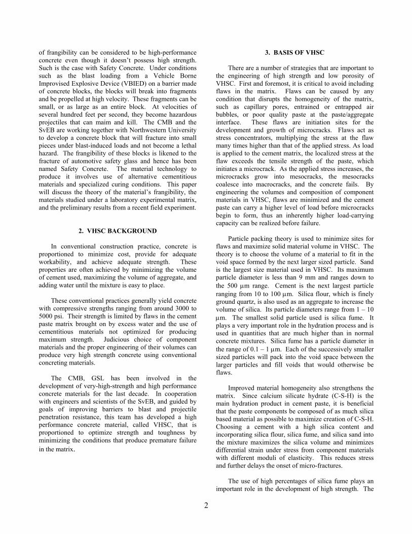
Preliminary conceptual designfor modular panels and supportingframe.
Some configurations for theconceptual design.
Survivability and Protective Structures Research
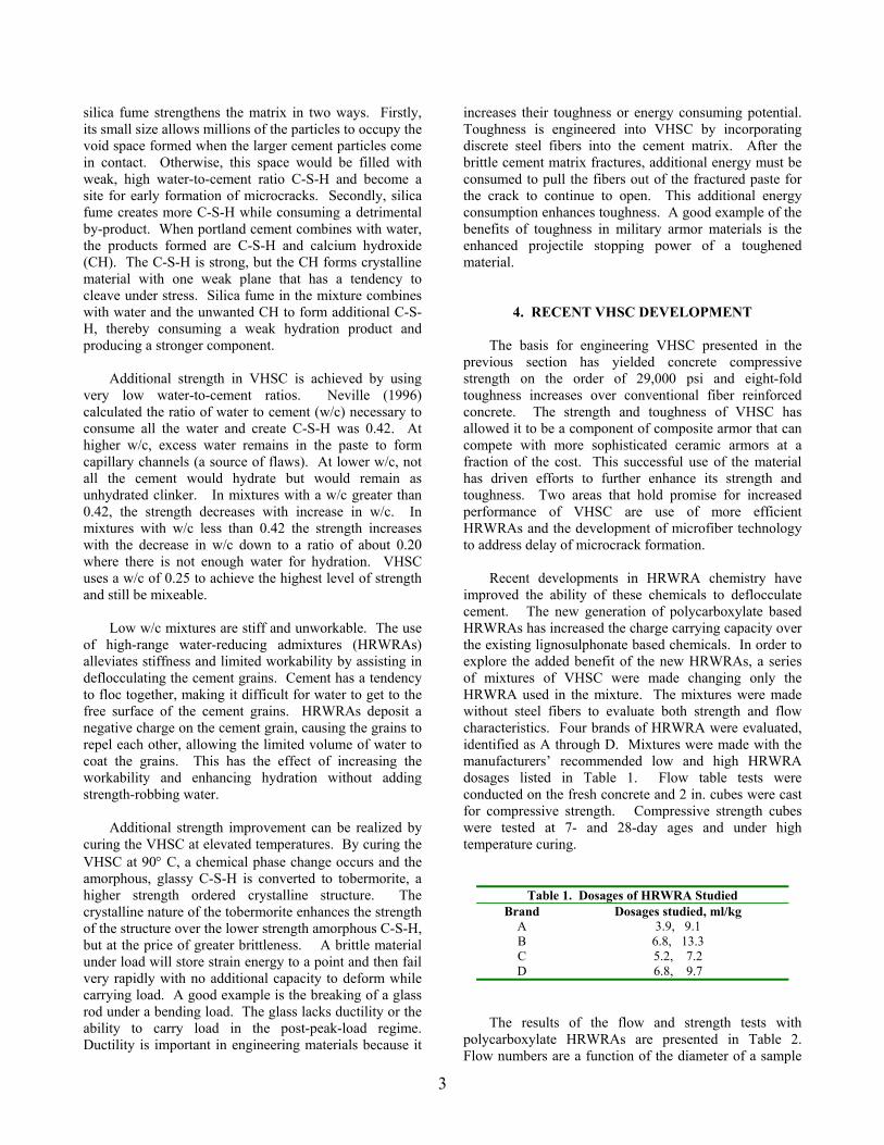
CompositeMaterials
VHSCConcrete
• Blast Resistance• Projectile Penetration Resistance• Low-Cost Armor Paneling• Impact Barriers• Special-need Structural Applications
VHSC is a core component in current composite armor panel work.
Uses:

3
Survivability and Protective Structures Research
What are High Strength and High Performance?
High Strength: As defined by ACI is any concrete withcompressive strength greater than 6000 psi.
High Performance: Superior performance from any property of a concrete for which the concrete has been designed.
Survivability and Protective Structures Research
05
10152025303540
ACI HSC IndustryUpper
Threshold
PreviousVHSC
Strength
CurrentVHSC
Strength
Relative Magnitudes of High Strength Concrete
Stre
ngth
, ksi
6
15
29
38
4
Survivability and Protective Structures Research
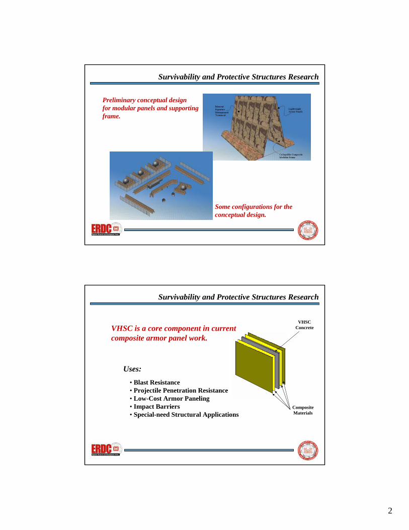
Engineering Concrete for High Strength• Use silica-rich dry components.
Maximize volume of silica for conversion to C-S-H.• Use particle packing techniques.
• Maximize C-S-H hydration product.Cement + water -> C-S-H + CH.
CH + silica fume -> C-S-H (and consumes CH).
• Minimize the volume of mixing water.Use a w/cm < 0.42 to minimize capillary formation.
Supplement workability with HRWRAs.
Employ heat curing.
• Combat brittleness by toughening matrix with fibers.
Survivability and Protective Structures Research
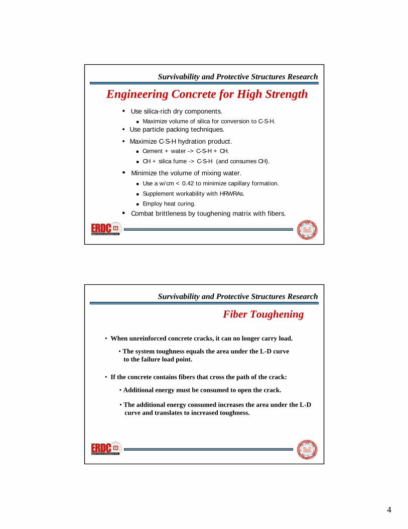
• When unreinforced concrete cracks, it can no longer carry load.
• If the concrete contains fibers that cross the path of the crack:
• Additional energy must be consumed to open the crack.
• The additional energy consumed increases the area under the L-Dcurve and translates to increased toughness.
Fiber Toughening
• The system toughness equals the area under the L-D curveto the failure load point.

5
Survivability and Protective Structures Research
Effect of Fiber Toughening
Typical load-deflection curvefor a non-fiber reinforced concrete
Survivability and Protective Structures Research
Effect of Fiber Toughening
Typical load-deflection curvefor a fiber reinforced concrete

6
Survivability and Protective Structures Research
Effect of Fiber Toughening
50 µm
40 mm
Macro fibers affect toughening across Macro cracks
(hook-ended steel fibers)
Micro fibers affect toughening across Micro cracks
(Wollastonite micro fibers)
Survivability and Protective Structures Research
Effect of Fiber Toughening
Micro fibers will have an affecton the concrete toughness side.
7
Survivability and Protective Structures Research
Effect of Fiber Toughening
Theoretical load-deflection curvefor micro-fiber assisted VHSC
Survivability and Protective Structures Research
Current VHSC Research Program
• Objective is to increase the VHSC strength and toughness.
• Baseline metric is old VHSC mixture.
• Studied the effects of new HRWRAs and microfibers.
• 4 new polycarboxylate HRWRAs studied.
• Addition of wollastonite microfibers.
• Variables of strength and workability studied.

8
Survivability and Protective Structures Research
Flow and Strength Results from Polycarboxylate HRWRAs
Strength, psi Brand Dose, Ml/kg Flow
7d 28d Heat Ctrl 16.86g - - - 24,945
3.9 29.8 19,880 21,786 30,833 A 9.1 102.8 18,027 21,729 20,991 6.8 56 20,316 26,008 35,151 B 13.3 128.9 18,975 24,423 32,765 5.2 61.8 19,844 25,751 34,433 C 7.2 122.1 20,052 23,961 35,778 6.8 61 19,229 19,782 34,752 D 9.7 112.2 19,626 21,645 30,568
Survivability and Protective Structures Research
Flow and Strength Results from Polycarboxylate HRWRAs with Microfibers
Strength, psi Brand Dose, Ml/kg Flow 7d 28d Heat
Ctrl 26.92g - - - 24,100 6.5 28.9 20,507 29,085 34,185 A 9.1 47.5 19,641 25,595 37,064 8.5 48.9 22,305 25,827 38,720 B 13.3 82.3 20,242 22,823 32,636 5.9 27.5 21,783 23,825 35,825 C 7.2 58.5 21,405 23,932 35,544 7.8 31.8 21,905 25,950 32,931 D 9.7 54.2 21,617 19,011 36,135
9
Survivability and Protective Structures Research
Strength vs type of HRWRA and Effect of Microfibers
05,000
10,00015,00020,00025,00030,00035,00040,00045,000
Control A B C D
HRWRA type
Heat
-trea
ted
Stre
ngth
, psi
'low dose w/o microfibers' 'high dose w/o microfibers''low dose w/ microfibers' 'high dose w/ microfibers'
Survivability and Protective Structures Research
Current and Future Areas of Study
• More study of micro-inclusions• currently studying the use of carbon nanofibers.
• Silicon whiskers.
• Extrusion molding of high-performance concrete shapes.
• Lightweight ceramic microspheres.• Polymer microfibers.
• Plates for modular panels.• Extruded structural shapes.