development of unmanned aerial vehicle systems for · pdf filethe application of unmanned...
TRANSCRIPT

INTERNATIONAL JOURNAL OF GEOMATICS AND GEOSCIENCES
Volume 5, No 3, 2015
© Copyright by the authors - Licensee IPA- Under Creative Commons license 3.0
Research article ISSN 0976 – 4380
Submitted on October 2014 published on January 2015 404
Development of Unmanned Aerial Vehicle Systems for Terrain Mapping
and Geospatial Data Management
Balaji Sethuramasamyraja, Nick Simonian, and Darnell Austin
Department of Industrial Technology, California State University, Fresno
2255 E Barstow Ave, M/S IT 09, Fresno, CA 93740-8002, USA
Impact Marketing Enterprises & Hydroponic Mastery Inc.,
Fresno, CA 93740, USA
ABSTRACT
The application of unmanned aerial vehicles (UAV) for short range civilian applications has
reached new dimensions with the advent of modern yet affordable autonomous guidance
systems. Low altitude light weight UAV systems were developed that have capability for
semi-autonomous and autonomous way point navigation with a payload of sensing system.
While UAV I was utilized to test the feasibility of application with manual control using
radio control and first person wireless video, UAV II was built for autonomous flight and
field data collection. With UAV II, in addition to an autopilot navigation system, a Global
Positioning Satellite (GPS) receiver and fight stabilization sensors were utilized for system
stability and guidance during completely autonomous flights. Both the UAVs successfully
performed in flight conditions for terrain mapping of property, range, agricultural and natural
resource management with respect to initial test flights, flight parameter calibration and field
trials. In UAV II, average calibration parameters were +/-0.64 deg. for pitch, +/-3.35 deg. for
roll in speed range of 40 - 50 mph indicating good flight stability. The UAVs were tested
over a user set waypoint path on fields, facilities/properties, and urban locales, altitude
ranging 100 ft to 1000 ft, speed from 25 to 60 mph, and maneuvers including straight paths,
turns, and banks. An autonomous image acquisition system was developed that records
images and videos with onboard sensors at specified time, frequency and coverage area. Geo-
referenced aerial images were created to 4 in. resolution using mosaic images and post
processing software. UAV I and UAV II maintained intended flight path parameters within
55 ft. and 8.23 ft. spatial position or cross track error, respectively.
Key words: Unmanned Aerial Vehicle, Autonomous Navigation, Farm Automation.
1. Introduction
Unmanned aerial vehicles (UAV) have shown rapid development in the recent past due to
availability of technology such as, autonomous navigation hardware, software and sensing
systems. UAV is typically defined as self-powered aerial vehicle that carries no humans,
uses aerodynamic forces for vehicle lift, fly autonomously or be remotely piloted and carry a
payload (Bone and Bolkcom, 2003). UAVs can be deployed quickly, operated in remote
areas and have relatively low operating cost. UAVs are commonly associated with defense
applications while they are constantly gaining popularity in civilian applications as well.
UAVs can benefit civilian applications such as, facilities/property management,
environmental surveillance, and terrain mapping for range/agricultural management,
photogrammetry and surveying (Doherty et al. 2000).

Development of Unmanned Aerial Vehicle Systems for Terrain Mapping and Geospatial Data Management
Sethuramasamyraja B et al
International Journal of Geomatics and Geosciences
Volume 5 Issue 3, 2015 405
Park and Ro (2004) developed a military UAV with high mobility and quick provision of
bird’s eye view video over hostile terrain with semi autonomous control using ground
operator, which was not realistic for civilian applications due to size and cost issues. Beard et
al. (2005) investigated the feasibility of avoidance system for use in military UAV
applications using semi autonomous larger aircrafts that were cost prohibitive for civilian and
scientific applications as well. In general, UAVs developed for defense were too customized
for military applications and not suitable for transfer to civilian use due to size, technology
and cost.
Hardin and Jackson (2005) developed a UAV with off-the-shelf components for low-altitude
large-scale photography for rangeland documentation. The stabilization technology available
then was limited and completely autonomous navigation was not viable which forced the use
of assisted stability control systems. Wang et al. (2008) developed a UAV system that adjusts
flight parameters in real time to provide detailed field information for decision making in oil-
gas application using neural network techniques that has become redundant now with
availability of standard flight stability and autonomous systems (hardware, firm ware and
software). Hirokawa et al. (2007) developed a simple UAV system for natural disaster
assessment and decision support on the fly through real time data relayed from onboard
sensors to a ground control station with the absence of flight stability study.
Herwitz et al. (2004) utilized a remotely controlled UAV for crop management of coffee
plantations including monitoring weeds, applying fertilizers & water, and also differential
harvesting based on fruit ripeness. This UAV was capable of completely autonomous flight
and could stay aloft for days while its large size and expensive development costs were
prohibitive for small scale civilian applications. Logan et al. (2005) reported the
technological challenges involved in small UAV development including size constraints,
development cost, lack of design and analysis tools and unique mission requirements. All
these factors add to the level of difficulty involved in the development of universal
lightweight UAVs that could be used in a variety of applications.
Although there are currently a variety of UAVs available in a range of sizes and navigation
methods which include full manual navigation control for the most basic aircraft as well as
fully autonomous navigation systems, a low cost and lightweight UAV that was easy to
deploy and completely autonomous with low fixed and operational costs for terrain mapping
in agriculture, natural resources and property management is uncommon. The basic goal of
this research was to develop a lightweight UAV that could be rapidly deployed and
autonomously controlled as applied economically in terrain mapping for property, range,
agricultural and natural resources management. The objectives were,
1. To assess feasibility of flight deployment in aerial terrain mapping, in relatively small
land parcels, < 100 acres while maintaining stability and consistent flight path
2. To design and develop of manual and autonomous aircrafts that collect geo-
referenced sensor data for decision making
2. Materials and Methods
2.1 UAV I – Manual Control
A fixed wing electric plane was designed from scratch and used an electric motor producing
200 W supplied by a lithium polymer 11.1 V 2.4 Ahr battery pack providing 12 min. flight
duration at single launch. UAV I has a 60 in. wingspan and total flying weight of 2.7 lbs
(Table 1).

Development of Unmanned Aerial Vehicle Systems for Terrain Mapping and Geospatial Data Management
Sethuramasamyraja B et al
International Journal of Geomatics and Geosciences
Volume 5 Issue 3, 2015 406
Table 1: UAV I Specifications
Wingspan
(in.)
Length
(in.)
Weight
(lbs)
Power (w) Rang
e(mi
n)
Payload
(lbs)
Max speed
(mph)
60 45 2.7 200 12 1 54
UAV I was piloted using handheld Futaba 6 Channel 72 MHz radio controller (Futaba,
Champaign, IL). Video data was collected by a charged coupled device (CCD) camera, Sony
SN555 1/3rd CCD (Sony Corporation of America, NY) mounted to pan and tilt gimbals
allowing for 360 deg. pan and 90 deg. tilt. UAV I was remotely controlled via real time
video feed wirelessly sent by T524 2.4 GHz 500 mW transmitter with a maximum range of 7
miles, on board to a ground station head display unit allowing navigation control.
Figure 1: UAV I. a. Manual Flight, b: Remote Real Time Control with First Person View
(FPV)
A second still camera the Canon SD 950 IS 12.1 mega pixel (Canon U.S.A., Inc., Lake
Success, New York) triggered by Futuba radio controller, was utilized for high resolution
orthographic pictures. Panorama Tools – Graphical User Interface, PT GUI (New House
Internet Services B. V., Rotterdam, The Netherlands) application photogrammetric software
was utilized for geo-referencing and stitching mosaic images. UAV I (Figure 1) was utilized
for mosaic image collection of a 36 acre alfalfa field through manual control. UAV I
collected image and video data at 30 mph airspeed, 450 ft. above ground in north-south
pattern with turns completed to allow 100 yd. pass to pass spacing. The image acquisition
was triggered manually using handheld Futaba radio controller in 10 s intervals. A second
flight was carried out over a riverbed (Main Fork, Three River, CA) using a single pass at
900 ft. altitude in east-west direction every 15 s.
2.2 UAV II – Autonomous Control
After successful initial results from UAV I a second UAV was developed to allow for
improvement of data and image collection. UAV II was designed with an electric motor
producing 425 W supplied by two lithium polymers 11.1 V 2.5 Ahr battery pack in parallel

Development of Unmanned Aerial Vehicle Systems for Terrain Mapping and Geospatial Data Management
Sethuramasamyraja B et al
International Journal of Geomatics and Geosciences
Volume 5 Issue 3, 2015 407
totaling 5Ahr. UAV II has a top mounted wing design for high lift using an under camber
airfoil 60 in. in length weighing 4.3 lbs with a maximum payload of 1 lb (Table 2).
Table 2. Specifications for UAV
Wingspan
(in.)
Length
(in.)
Weight
(lbs)
Power (w) Rang
e(min
)
Payload
(lbs)
Max speed
(mph)
60 46 3.3 425 15 1 67
The intended waypoint flight path was constructed in Google Earth (Google Inc., Mountain
View, CA) software. Using the line path tool, a waypoint navigation flight path with airspeed,
altitude parameters, camera trigger location and time interval was created for autonomous
navigation system, AttoPilot v. 1.8 beta (AttoPilot LLC, Gilbert, AZ). UAV II was manually
controlled during initial hand launch and then switched to autonomous mode before the first
waypoint. Canon SD 950 IS 12.1 mega pixel camera was used for still image capture that
was auto-triggered by Attopilot according to presets.
2.3 Navigation and Stability System Calibration
During calibration flights, UAV II had high roll and pitch oscillations that required gain
settings adjustments to improve mosaic image quality. Table 3 lists the flight conditions
while capturing images. During calibration flight runs, the flight parameter log file is updated
at 5Hz frequency and pitch, roll, speed, heading, data fields as well as other log data was used
for precision adjustment of gain settings. The gain value (0 – 100) for PID controller was user
set (Table 4). Among the seven servo settings, camera stabilization servos were not used
while rudder servo was disabled to suit UAV II wing design.
Table 3: Flight Parameters during UAV II Calibration run to acquire still images
Photo
Number
Pitch
(deg.)
Roll
(deg.)
Altitude
(ft.)
Camera
trigger error
(ft.)
Heading
(deg.)
Speed
(mph)
1 -2.59 -8 606 6 150 42
2* 2.19 .0.64 570 6 138 43
3 5.35 -.16 544 0 142 41
4 4.93 -4 541 0 146 41
* Refers to < 3.5 degrees maximum allowed pitch or roll for photo collection.
A maximum allowed pitch or roll angle of 3.5 degrees for each image was used to determine
if that image would be usable for the creation of the final mosaic image. Pitch or roll angles
above 3.5 degrees tend to create large distortion of the mosaic image and degrade its usability
and accuracy. It’s clear that only one image met the minimum requirements requiring
further gain adjustments for oscillation dampening. Roll and pitch oscillations are evident in
log files and review of log files is used to make PID adjustments. (Figure 2a and 2b).

Development of Unmanned Aerial Vehicle Systems for Terrain Mapping and Geospatial Data Management
Sethuramasamyraja B et al
International Journal of Geomatics and Geosciences
Volume 5 Issue 3, 2015 408
-20
-10
0
10
20
30
40
50
1 9 17 25 33 41 49 57 65 73 81 89 97 105 113 121
Degrees
Time (0.2 s Intervals)
Pitch and roll before adjustments
pitch
Roll
-20
-10
0
10
20
30
40
50
1 9 17 25 33 41 49 57 65 73 81 89 97 105 113 121Decimal Degrees
Time (0.2 s Intervals)
Pitch and roll after adjustments
pitch
roll
Figure 2: Pitch & Roll after adjustments - executes a 90 deg. turn into a 450 yd. straight line
path after PID fine tuning. a. P and D for Roll - 45 & 2. Pitch P and D for Pitch - 33 and 0,
and b. P and D for Roll - 34 & 10. Pitch P and D for Pitch - 58 and 18
UAV II flight stability requires adjustment of automatic servo response time using
Proportional-Integral-Derivative, PID controller gain setting. Integral gain values were auto-
generated based on user set proportional and derivative gain settings that enabled UAV II
react to its dynamic environment by producing controlled pitch, roll and speed changes for
path tracking.
UAV II autonomous stabilization was achieved with thermopile sensors that send analog
feedback signal to the Attopilot system, operating in 5.5 and 15 microns infrared spectrum
based on the difference between sky and ground temperature. The Attopilot system also has
an absolute barometric pressure sensor and pitot tube airspeed sensor as a feedback loop to
increase precision and minimize failure.
UAV I and UAV II path tracking performance could be evaluated using cross track error
parameter which is defined as the difference between intended and the actual path or mean
actual distance in ft. of separation between the intended and actual path. In the case of manual
flight, a set of reference points or ground markers were utilized as the intended path while the
actual path was recorded using an onboard GPS system. In the event of autonomous mapping,
a true geo-referenced intended path was loaded to the UAV II system prior to launch which
was compared to the actual path tracked by the GPS system.
Development of Unmanned Aerial Vehicle Systems for Terrain Mapping and Geospatial Data Management
Sethuramasamyraja B et al
International Journal of Geomatics and Geosciences
Volume 5 Issue 3, 2015 409
Table 4: Attopilot Gain Settings
Servo Proportional Gain
Settings
Derivative Gain
Settings
Control
Parameter
1 34 10 Aileron (Roll)
2 58 18 Elevator (Pitch)
3 24 0* Throttle
4 Disabled Disabled Rudder (Yaw)
5 Not Used Not Used Camera
Stabilization
6 Not Used Not Used Camera
Stabilization
7 100 0* Camera Trigger
* For Throttle: manufacturer recommended ‘0’due to lack of precision in sensor that
determines rate of change of air speed with respect to time and For Camera Trigger: D gain
setting was not required
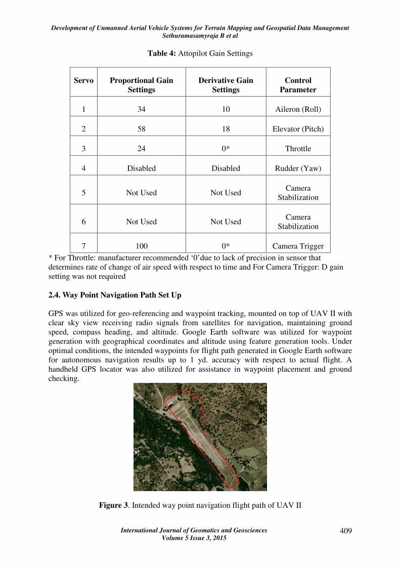
2.4. Way Point Navigation Path Set Up
GPS was utilized for geo-referencing and waypoint tracking, mounted on top of UAV II with
clear sky view receiving radio signals from satellites for navigation, maintaining ground
speed, compass heading, and altitude. Google Earth software was utilized for waypoint
generation with geographical coordinates and altitude using feature generation tools. Under
optimal conditions, the intended waypoints for flight path generated in Google Earth software
for autonomous navigation results up to 1 yd. accuracy with respect to actual flight. A
handheld GPS locator was also utilized for assistance in waypoint placement and ground
checking.
Figure 3. Intended way point navigation flight path of UAV II

Development of Unmanned Aerial Vehicle Systems for Terrain Mapping and Geospatial Data Management
Sethuramasamyraja B et al
International Journal of Geomatics and Geosciences
Volume 5 Issue 3, 2015 410
Typically, Google Earth line tool was used to create the intended flight path in the area of
interest (Figure 3). After creating a Keyhole Markup Language, KML format file with geo-
coordinates, it was post processed using an executable Attopilot Software and the resulting
text file was appended with airspeed and camera triggers for each waypoint before loading to
Attopilot system onboard UAV II.
3. Results and discussion
3.1 UAV I – Manual Control
UAV I with a GPS receiver and a wireless video camera/transmitter were utilized for flight
path simulation in a small parcel area, specifically an alfalfa field (Figure. 4). The GPS
receiver on board operating at 1 Hz. frequency in the east-west direction collected actual
flight path geographical coordinate at the rate of 1 point per second as overlaid on a Google
earth image of alfalfa field (Figure. 4). Flying 400 ft. above ground at 30 mph, UAV I
captured a data geographical coordinate using GPS receiver every 20 yd. at 1 s interval
indicating feasible spatial data collection using sensors. The total time elapsed to cover 66
acres with 1 Hz. frequency data collection was only 20 min including launch, set up and
flight path acquisition. UAV I was successful in maneuvering turns as tight as 20 yd radius,
which is good spatial resolution for sensor data on relatively small land parcels like
agricultural fields. Video feed aided manual navigation purposes from a bird’s eye view for
ease of control by the flight operator at ground.
Figure 4. UAV I manual flight path captured by on board GPS receiver at 1 Hz. frequency
while flying at 30 mph & 400 ft above ground flight path over Google Earth Image.
Figure 5. Mosaic image of 36-acre alfalfa field captured manually. Mosaic created from
approximately 20 photos. Large distortion and misalignment is evident.
Manual Path (GPS Recording)

Development of Unmanned Aerial Vehicle Systems for Terrain Mapping and Geospatial Data Management
Sethuramasamyraja B et al
International Journal of Geomatics and Geosciences
Volume 5 Issue 3, 2015 411
UAV I with a still image camera on board, manually triggered image data collection every 10
s resulting in 0.1 Hz. frequency while flying 450 ft above ground covering 36 acres in 12
min. Twenty usable images were used for building a mosaic image (Figure 5) of the alfalfa
field, which were geo-referenced and stitched using remote sensing post processing using PT
GUI software.
The mosaic image generated could spot areas of variability with respect to soil, vegetation
and weed outbreaks. However, mosaic image creation was bound to high degree of distortion
due to variation in bank angle caused by pitch and roll. This explains the manual control
stability was difficult in high wind turbulence as executing smooth equal turning radius was
not achievable to high degree of precision of +/- 2.5 deg. along the intended route due to
constant crosswind corrections, lack of aircraft attitude feedback and pilot error. Further
difficulty resulted from attempting to hold course while maintaining pitch and roll near 0 deg.
during image capture. Essentially, due to high degree of pitch and roll during each image
capture, mosaic generated had degraded quality in the alfalfa field. The cross track error
between the actual flight path and intended flight path using reference ground markers along
the path of data acquisition is an estimated average of 55 ft excluding the turns. The extent of
this estimated error is highly variable based on pilot skill level as well as weather conditions.
A second test with UAV I with a still image camera on board, manually triggered image data
collection every 10 s resulting in 0.1 Hz. frequency while flying 120 acres in less than 12
min. Ten usable images were used for building a mosaic image (Figure 6) of the Main Fork
River, Three Rivers, CA using the PT GUI software. Distortion of the mosaic image
collected on this application was less due to reduced wind and a simpler straight path not
requiring turns (Figure 6).
Figure 6. Singe pass mosaic image of Main Fork Riverbed, Three Rivers, CA
3.2 UAV II – Autonomous Control
A multi pass waypoint intended path was developed for Town Arena, Three Rivers, CA for
property/event management (Table 5). The flight length was 2500 ft per pass and 278 ft
between passes while capturing digital images every 295 ft. While the total flight path is 9500
ft, the actual photo coverage length is only 4500 ft due to turns involved.

Development of Unmanned Aerial Vehicle Systems for Terrain Mapping and Geospatial Data Management
Sethuramasamyraja B et al
International Journal of Geomatics and Geosciences
Volume 5 Issue 3, 2015 412
Table 5: Multi-pass mosaic image collection parameters for Town Arena, Three Rivers, CA
Relative
Altitude
(ft)
Speed
(mph)
Total
flight
path (ft)
Camera
trigger
distance
(ft)
Major length
and Width of
Flight path
(ft)
Distance of total
flight path used for
photo collection (ft)
984 41 9500 295 2500 & 560 4500
UAV II was hand launched from near the target location and manually piloted to 984 ft.
above ground and then switched to autonomous mode. The UAV maintained preset heading,
airspeeds, and altitudes while navigating the course and collected images every 295 ft along
intended waypoint flight path. (Figure 7) A total of fifteen images were collected over the
Town Arena, Three Rivers, CA.
Figure 7. UAV II Intended (Lighter) vs. Actual (Darker) Flight path over Town
Arena, Three Rivers, CA
Table 6: Roll, pitch and heading of image captured during multi pass test run of Town Arena,
Three Rives, CA
Image Pitch
(deg.)
Roll
(deg.)
Heading
(deg.)
Actual Air
Speed
(mph)
Actual
Altitude
(ft)
1 -1.29 +13.6 312 (NW) 47.8 1106
2 -1.02 +8.48 327 (NW) 46.6 1073
3* -0.39 +0.06 330 (NW) 44.1 1063
4* +0.09 +0.25 324 (NW) 44.1 1063
5 -0.27 +4.95 324 (NW) 43.4 1057
6* +0.37 -2.96 147 (SE) 41 1023
7* +0.85 -1.56 144(SE) 40.4 1023
8* +0.21 +0.01 144(SE) 41 1020
9* +2.23 -0.98 144(SE) 40.4 1020

Development of Unmanned Aerial Vehicle Systems for Terrain Mapping and Geospatial Data Management
Sethuramasamyraja B et al
International Journal of Geomatics and Geosciences
Volume 5 Issue 3, 2015 413
10* +0.93 -0.85 145(SE) 40.4 1017
11 +0.50 -4.39 325(NW) 38.5 1017
12 -0.17 +8.23 320(NW) 40.4 1004
13* -0.03 +3.56 326(NW) 41 1007
14* +0.14 +0.39 327(NW) 40.4 1010
15* -1.11 +0.09 326(NW) 40.4 1020
Average 0.64 3.35 NA 42 1034 * Refers to < 3.5 deg. Cut Off for better image quality
UAV II intended and actual flight paths during image capturing showed consistent
performance along the intended flight path shown in white. The intended flight path is loaded
to the UAV at launch and is executed immediately upon switching to autonomous flight. The
intended path is the exact course the UAV should attempt to follow. Ideally the actual path
should not deviate from the intended path however due to a necessary turn radius a noticeable
deviation for intended path is expected whenever the UAV must change direction to stay on
course. The cross track error between the actual flight path and intended flight path along the
path of image capture is an average 8.23 ft excluding the turns as no image was captured
during turns enabling accurate mosaic image acquisition. Table 6 lists UAV II image
collection parameters of 7 min data acquisition including take off and landing.
Figure 8. Mosaic image of Arena, Three Rivers, CA created using the 10 images listed in
Table 6.
Of the 15 images shown in table 6 only 10 images were used for the mosaic image creation
(Figure. 8) of Town Arena, Three Rivers, CA. These 10 images were selected because they
had a roll and pitch angle equal to or less than 3.5 degrees. Due to the low roll and pitch error
and the ability to maintain target altitude and heading a mosaic image with minimal distortion
was rapidly collected. An average 0.64 deg. pitch, 3.35 deg. roll, 42 mph actual air speed
against intended 41 mph and 1034 ft. actual altitude against intended 984 ft. were achieved.
UAV II collected about ten different mosaic images and video from applications such as
property/event management, cemetery, golf course, arena, agricultural field and ranges both
during calibration runs, testing and image/video data collection.
4. Conclusion
UAVs were developed to working prototypes, one of which, UAV I with manual control was
utilized for feasibility study and the other, UAV II with autonomous control capable of GPS

Development of Unmanned Aerial Vehicle Systems for Terrain Mapping and Geospatial Data Management
Sethuramasamyraja B et al
International Journal of Geomatics and Geosciences
Volume 5 Issue 3, 2015 414
based waypoint navigation with on board cameras that collected high resolution images and
video for decision making. Remote sensing post processing software was used to geo-
reference and stitch individual images to mosaics. The mosaic images and video data
collected in various applications including facility sites, ranges, agricultural fields and other
terrains were utilized for management decision making by discipline experts.
UAV II showed consistent results with an average cross track error of 8.23 ft and provides a
viable system for autonomous aerial image acquisition. UAV II average calibration
parameters were +/-0.64 deg. for pitch, +/-3.35 deg. for roll in speed range of 40 - 50 mph
airspeed enabling a stable platform for waypoint path tracking with intended target speed and
altitude. UAV I and II with on board sensing systems successfully collected about 150
different runs for mosaic images, videos and data collection including property/event
management, agricultural fields and ranges during calibration runs, testing and data collection.
The total flying time (excluding field set up, ground testing, calibration and troubleshooting)
during this research with UAVs were 3 hr in manual mode and 12.5 hrs in autonomous mode,
respectively.
Acknowledgements
Partial support for this research was provided by Dr. Jim Yager (Impact-Ag, Fresno, CA), Mr.
Gino Fargovsa (Fargovsa Farms, West Fresno), and Department of Industrial Technology
(California State University, Fresno). Partial funding was provided by our industry sponsor
Digi-Star, Fort Atkinson, WI.
6. References
1. Beard, R., Kingston, D., Quigley, M., Snyder, D., Christiansen, R., Walt, J., McLain,
T., and Goodrich, M.A. (2005), Autonomous Vehicle Technologies for Small Fixed-
Wing UAVs. Journal of Aerospace Computing, Information and Communication, 2,
pp 92 - 97.
2. Bone, E., and Bolkcom, C. (2003), Unmanned Aerial Vehicles: Background and
Issues for Congress. Report for Congress. pp 1-47.
3. Doherty, P.; Granlund, G.; Kuchcinski, K.; Nordberg, K.;Sandewall, E.; Skarman, E.;
and Wiklund, J. (2000), WITAS unmanned aerial vehicle project. the 14th European
Conference on Artificial Intelligence. 747–755. 4. Almond Lifecycle and Growth.
(2010). Almond Board of California, Modesto, CA, USA.
4. Hardin P.J and M. W. Jackson (2005), An Unmanned Aerial Vehicle for Rangeland
Photography. Rangeland Ecology & Management 58(4), pp 439-442.
5. Herwitz, S. R., Johnson, L. F., Dunagand, S. E., Higgins, R. G., Sullivand, D.V.,
Zhengc, J., Lobitzc, B. M., Leunge, J. G., Gallmeyere, B. A., Aoyagi, M., Slye R. E.,
and Brass J. A. (2004), Imaging from an unmanned aerial vehicle: agricultural
surveillance and decision support. Computers and electronics in agriculture, Pp 49-61.
6. Hirokawa, R., Kubo, D. Suzuki, T. Suzuki, S. Meguro, J. (2007). Real-time hazard
map generation using small unmanned aerial vehicle. Proceedings of the Society of
Instrument and Control Engineers Annual Conference, pp 443-446.

Development of Unmanned Aerial Vehicle Systems for Terrain Mapping and Geospatial Data Management
Sethuramasamyraja B et al
International Journal of Geomatics and Geosciences
Volume 5 Issue 3, 2015 415
7. Logan, M, Vranas, T, Motter, M, Shams, Q, and Pollock, D. (2005). Technology
challenges in small UAV development. InfoTech at Aerospace: Advancing
Contemporary Aerospace Technologies and Their Integration, American Institute of
Aeronautics and Astronautics, 3, pp 1644-1648.
8. Park, J,and Ro, K. (2004). A prototype design, test and evaluation of a small
unmanned aerial vehicle for short-range operations. “Unmanned-Unlimited"
Technical Conference, Workshop, American Institute of Aeronautics and
Astronautics, 2, pp 688-695.3.
9. Wang, T. M., Lei, X, Linag, J, and Pei, B. (2008). A small unmanned aerial vehicle
for oil-gas field surveillance. Proceedings of the 7th International Conference on
Machine Learning and Cybernetics, Institute of Electrical and Electronics
Engineering, 4, pp 1840-1846.6.