development of the vibration isolation system for … · 1 development of the vibration isolation...
TRANSCRIPT
1
Development of the Vibration Isolation System for t he Advanced Resistive Exercise Device
Jason H. Niebuhr* and Richard A. Hagen**
Abstract This paper describes the development of the Vibration Isolation System for the Advanced Resistive Exercise Device from conceptual design to lessons learned. Maintaining a micro-g environment on the International Space Station requires that experiment racks and major vibration sources be isolated. The challenge in characterizing exercise loads and testing in the presence of gravity led to a decision to qualify the system by analysis. Available data suggests that the system is successful in attenuating loads, yet there has been a major component failure and several procedural issues during its 3 years of operational use.
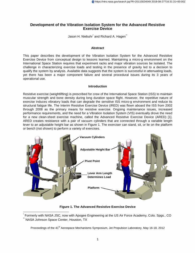
Introduction Resistive exercise (weightlifting) is prescribed for crew of the International Space Station (ISS) to maintain muscular strength and bone density during long duration space flight. However, the repetitive nature of exercise induces vibratory loads that can degrade the sensitive ISS micro-g environment and reduce its structural fatigue life. The Interim Resistive Exercise Device (iRED) was flown aboard the ISS from 2002 through 2008 as the primary means for resistive exercise. Ongoing maintenance issues, increased performance requirements, and the need for a Vibration Isolation System (VIS) eventually drove the need for a new clean-sheet exercise machine, called the Advanced Resistive Exercise Device (ARED) [1]. ARED creates resistance with a pair of vacuum cylinders that are connected through a variable length lever to an adjustable height bar as shown in Figure 1. The exerciser can stand, sit, or lie on the platform or bench (not shown) to perform a variety of exercises.
* Formerly with NASA JSC, now with Apogee Engineering at the US Air Force Academy, Colo. Spgs., CO ** NASA Johnson Space Center, Houston, TX
Proceedings of the 41st Aerospace Mechanisms Symposium, Jet Propulsion Laboratory, May 16-18, 2012
Vacuum Cylinders
Figure 1. The Advanced Resistive Exercise Device
Lever Arm Length Determines Load
Pivot Point
Adjustable Height Bar
Platform
https://ntrs.nasa.gov/search.jsp?R=20110024049 2018-08-27T16:31:31+00:00Z

2
The primary micro-g requirement is a frequency-dependent acceleration limit at the US Lab and Columbus module rack interfaces. Structural dynamics transfer functions are available to quantify the acceleration at those racks as a function of input load at the ARED location within the ISS. With the assumption of equal loading in all axes, the acceleration limit and transfer functions can be taken together to consider the requirement in terms of allowable load. A similar frequency-dependent load limit is required to preserve ISS fatigue life. The composite allowable load enveloping both micro-g and structural fatigue requirements is shown in Figure 2. This is a simplified and conservative view of the
requirements, yet highly insightful. The graph highlights the most significant challenge to the design; a major ISS structural mode exists near 0.24 Hz which can be seen as a steady state allowable load of only 1.7 N (0.4 lbf) between 0.18 Hz and 0.28 Hz. As shown by the shaded area of the graph, this is well within the 0.09 Hz – 1.18 Hz range of exercise frequencies recorded during the ARED man-in-the-loop test (MILT) [2]. Analysis of the ARED in a non-isolated configuration suggests that exercise loads can be as a high as 67 N (15 lbf) at 0.24 Hz, requiring attenuation by more than an order of magnitude.
Analytical Approach A rigid body dynamic model was created in the motion analysis software visualNastran 4D from MSC.Software Corporation. This software was chosen over general numerical computing codes for its native 3D visualization capabilities and ease of use. This made it possible to examine many different design concepts and better understand how they worked. Though somewhat controversial, it was felt that the cost and complexity of an actively-controlled isolation system wasn’t justified. Being able to visually simulate system dynamics was essential in convincing both technical and non-technical stakeholders alike that a passive isolation system would be sufficient. Model development focused on three distinct elements: a geometrical and mass model of the ARED, a geometrical and mass model of the exercising crew member, and a mathematical model of the VIS. Development of the ARED model was straightforward as solid geometry was imported from computer-aided design (CAD) software after being simplified into 12 major subcomponents by suppressing details like fasteners, fillets, and lightening pockets. Detailed mass properties of the subcomponents were retained from the original CAD model. Appropriate constraints were applied to the model to simulate fixed, rotational, and sliding joints. Capturing this level of detail kept the computing requirements manageable. The exercise model consists of a CAD model human constrained to simulate exercise motion when driven by displacement. Figure 3 illustrates how the human model and subcomponents of a non-isolated ARED
Figure 2. Allowable Loads Requirement and Exercise Frequency Range
Exercise Frequency Range 0.09 Hz – 1.18 Hz

3
both move throughout the stroke of a squat exercise. The y-axis is parallel with the long axis of ARED, the z-axis positive toward the exerciser, and the x-axis completes the right-handed Cartesian system. Exercise variables include type, stroke, crew size, and frequency. The exercise types and stroke lengths range from a squat moving nearly 90% of the body’s mass through 0.70 m (27.5 in) of stroke to a neck flexion that moves less than 6% of the body’s mass through less than 0.23 m (9 in) of stroke [3]. However, the squat, dead lift, straight leg dead lift, and heel raise are worst-case and envelope all other exercises in the analysis because they move the most amount of body mass over the greatest distance. The 95th percentile American male represents the heaviest crew analyzed while the 5th percentile Japanese female is the lightest [4]. Data from the ARED MILT defines exercise stroke profiles and statistically quantifies exercise frequency. Figure 4 shows a box plot of the exercise frequencies for 3 of the worst-case exercises. The middle dash represents the average frequency, the box envelopes ± 1 standard deviation, and the whiskers represent the extreme value recorded. Either idealized sinusoidal or
real stroke profile data derived from testing can be used to drive the human exercise model. Use of idealized sinusoidal data tends to be more severe because spectral energy is focused into a singular frequency, whereas real stroke profiles capture the inherent variability in human exercise. The idealized sinusoidal approximation becomes worse at lower exercise frequencies that are typically distinguished by longer pauses between exercise cycles. The VIS model consists of mathematical definitions of spring and damping rates. Many different concepts were examined and several lessons learned:
1) The enveloping exercises only excited the system in 3 degrees of freedom (DOF) planar motion: Translation along the y- and z- axes, and rotation about the x-axis. Trading mounting rigidity for
Figure 3. Non-Isolated ARED and Human Model Motion During Squat Exercise
Y
Z
Figure 4. Box Plot of Frequency Statistics for 3 E xercises

4
isolation by reducing stiffness in only these 3 DOF is both sufficient and provides a certain level of safety when suspending nearly 567 kg (1250 lbm) in a micro-g environment.
2) Each enveloping exercise excites the 3 DOF differently. Squats and heel raises primarily excite the y-axis and rotation about the x-axis. Dead lifts, particularly the straight leg variant, tend to excite all 3 axes.
3) Decoupling the VIS DOF by lining them up with the ISS axes made the design of the system much easier. Changes to spring or damping rates in one axis only affect that axis.
4) Analysis lessons learned 2 and 3 combined with the knowledge that structural dynamics transfer function response varied in each axis allowed the stiffness and damping of the system to be optimized against the micro-g and structural fatigue requirements.
A key principle in vibration isolation is choosing isolator properties such that the natural frequency of the system is below the forcing frequency. In this case the forcing frequency is the aforementioned exercise frequency range from 0.09 Hz to 1.18 Hz. The natural frequency, fn, is given by:
�� =1
2����(��) Where k is the spring rate and m is the mass. Additional damping was added to more quickly dissipate energy in the system. Transmissibility, T, is a measure of the amplification of the isolation system or ratio of output to input. It is given by:
=
�1 + 2 ∙��� ∙ ���
�2 ∙��� ∙ ��� + 1 − ����
���
Where f is the forcing frequency and ζ is the ratio of damping to critical damping. Values of T > 1 signify an amplification of input load, whereas values of T< 1 signify an attenuation of input load. The chosen spring rates, percent damping, resultant natural frequencies, and amplification at various frequencies are shown in Table 1 for each of the 3 DOF.
Table 1. VIS Properties and Isolation Qualities
Axis Spring Rate Damping Natural
Frequency Amplification, T
(0.09 Hz ) Amplification, T
(0.24 Hz) Amplification, T
(1.18 Hz)
Y 70 N/m
(0.4 lbf/in) 11% 0.06 Hz 0.7 0.08 0.01
Z 175 N/m (1 lbf/in)
10% 0.09 Hz 1.9* 0.19 0.02
X (rotation)
0.6 N•m/deg (5.2 in•lbf/deg)
17% 0.05 Hz 0.4 0.08 0.01
* Amplification based on 0.11 Hz minimum deadlift exercise frequency since the squat exercise creates minimal
excitation in z-axis

5
The spring rates, particularly in the y-axis, had to be extremely low to keep the natural frequency of the system from overlapping the exercise frequency range and to meet the micro-g and fatigue requirements. The z-axis motion is generally only a fraction of what is seen in either of the other two axes which is why the spring rate and the resultant natural frequency was increased to nearly encroach upon resonance in a worst-case scenario. This was necessary to minimize the motion envelope; one of several other issues that developed as a result of the low spring rates. Inertial accelerations applied to ARED and friction forces also became issues. While ARED is allowed to move in response to exercise, the inside of the ISS is a relatively limited space and there was a possibility that a crew member could hit their head while exercising. Travel limits were setup to prevent this from occurring. Another consideration was the effect of inertial accelerations applied to the ARED system as a result of events like reboost and docking. These events are enveloped by a 0.4 g load factor applied in any direction and cause the ARED to move across the motion envelope and collide with the end of travel limits. This potentially overloads the interface and exceeds a transient acceleration micro-g requirement. Much larger dampers, called snubbers, were sized and located at the travel limits to attenuate those loads. They were selected by calculating the velocity of ARED due to the inertial acceleration and sizing them to efficiently dissipate the energy. Friction had to be considered because, if too high, it had the effect of causing the entire system to “inch-worm” until it reached one end of the motion envelope, potentially reacting repeatedly against the end of travel limits and not re-centering. A special effort was made during the mechanical design phase to select components with low friction as well as to include its effects within the analytical simulation.
Mechanical Design
To stay within cost and schedule constraints many commercial off-the-shelf (COTS) components are used in the design of the VIS. It is a nearly symmetrical assembly composed of 2 plate assemblies connected by a beam as shown in Figure 5.
Figure 5. The Vibration Isolation System
VIS
ARED
Y Plate
Z Plate
Rotation Housing
Interface to ARED
Rotation Arm

6
Each side has half of the linear and rotational bearings that constrain motion to 3 DOF and the isolation components that attenuate exercise loads. Figure 6 shows that the Y Plate contains linear rails, springs, and dashpots that connect to the Z Plate, allowing motion in the y-axis. The Z Plate has the same components that allow the Rotation Housing to move in the z-axis. Lastly the Rotation Housing has a bearing to allow rotational motion and an arm to convert linear spring and damper forces into torque about the x-axis. The allowable deflection between the left and right plates was specified as ± 0.051 mm (± 0.002 in) to reduce the possibility of the VIS binding under load. This placed a burden on manufacturing since interface joints and bearing rail surfaces were held to extremely tight tolerances. To minimize misalignment due to accumulated tolerances, there are only 11 VIS structural components from one side of ARED to the other. The VIS was assembled in a fixture to verify alignment and set the spacing of the 2 halves. The linear bearings that constrain motion were chosen from amongst several candidates. The DualVee guide wheel design exhibited low friction, robustness, and ease of maintenance. Rails are made from 420C stainless steel while the bearings are made from 440C stainless steel, simplifying the material certification process. The low bearing friction is achieved by using a bearing with shields instead of seals, high quality Rheolube 2000 grease, and just enough bearing preload to maintain linear rigidity. The preload in the bearings is adjusted until the maximum load needed to move a given plate is 1.3 N (.3 lbf). The double row angular contact design of the DualVee provides a robust bearing that can handle large static loads. Finally, by separating the bearing elements from the track as shown in Figure 7, maintenance is significantly reduced since dirt and debris attracted to the rails does not come in contact with the ball bearings. They also have a better tolerance for bearing misalignment than other linear bearing systems tested.
Linear rails allow the Z plates to move in the y -axis
Linear rails allow the Rotation Housing to move in the z -axis
A rotational bearing allows moti on about the x -axis
Rails Dashpots Springs
Figure 6. The Left Plate of the Vibration Isolatio n System
Motion
Motion Motion
Figure 7. DualVee Bearing and Rail

7
Rotational motion of the VIS is constrained with a SKF double row angular contact bearing that also uses shields instead of seals and is lubricated with Rheolube 2000. Low rate springs attenuate exercise loads in all axes. 17-7 PH stainless steel extension springs are preloaded against one another to maintain a constant spring rate across the motion envelope and keep ARED centered. Compression springs were not favored because the combination of length and low spring rate would have required a support to prevent buckling. It was felt that the resultant friction would have reduced spring life, increased load variability, and perhaps resulted in a noise problem. The dashpots act to dissipate energy in the system by reacting to motion with a force proportional to velocity. Airpot dashpots were chosen for their simple design, use of an inert working fluid (air), adjustability, and advertised long life. A similar component is successfully used in the Active Rack Isolation System that protects ISS experiment racks from vibration. The dashpots consist of a carbon-graphite piston in a borosilicate glass cylinder with Rulon-lined ball joints at each end of the piston rod to allow for misalignment as shown in Figure 8. An adjustable screw orifice with a check valve adjusts the damping rate in the pull direction. The dashpots are wrapped with Kapton tape to contain debris in the event of breakage.
The snubbers that attenuate impact loads from reboost and docking events are located to engage at the end of the motion envelope. Oil-filled models from ACE Controls were chosen because of their compact size and adjustability. The rotation axis snubbers are shown in Figure 9.
Figure 8. Airpot Dashpot
Adjustable Orifice
Graphite Piston Glass Cylinder
Figure 9. Snubbers Mounted in the Rotation Housing

8
A lock-out pin inserted by the crew passes through the rotation arm and both plates, anchoring the VIS in the centered position to protect it from damage when not in use. In addition to creating simple crew interfaces, significant effort was expended in designing the VIS to be easy to inspect, repair, or even upgrade if needed. All of the isolation components are accessible by removing covers and serviceable using standard ISS tools. Individual components are replaceable instead of requiring large subassemblies to be kept as spares. The VIS attachment to the seat track in ISS is designed to accommodate misalignment due to initial tolerance variations or changes over time due to temperature or pressure fluctuations. This is accomplished by attaching at 3 points with sliding trunnions through spherical bearings as shown in Figure 10.
This statically determinant mounting method does not transfer torque to the relatively torque-intolerant seat track. Installation was greatly simplified and crew can remove and replace the entire ARED and VIS system easily for relocation, emergencies, or storage access.
Test and Qualification Approach Testing VIS performance is difficult in the presence of gravity. An earlier development program attempting to isolate the iRED tested the system lying sideways on an air bearing floor. The human subject was also supported sideways to perform exercises, which was very difficult and cast doubts on the validity of the results. A parabolic flight pattern on a reduced gravity aircraft provides a more realistic environment to perform exercises, but the window of weightlessness is too short and given the extremely low spring rates, there is significant risk of hardware damage during the pull-out phase of flight. Even testing on-orbit may not capture worst-case exercise scenarios due to natural human variability. While a test of system level performance was impractical, a test program was developed to:
1) Verify that components meet performance requirements and adjust those with variable settings
2) Life cycle test the system to identify and resolve potential issues
3) Gather component performance data for the system level qualification analysis model The test stand consists of a Motion Science MS700 electromechanical actuator (EMA), Sensotec Model 31 load cell, and a string potentiometer all mounted on a t-slot table as illustrated in Figure 11.
Misaligned
X
Y
Each spherical bearing is attached to seat track and independently constrains 2 linear DOF. As a system they constrain all 6 DOF.
If one spherical bearing (attachment point) moves, a combination of sliding (trunnion) and rotation
(spherical bearing) at all 3 locations self-aligns the
system.
Figure 10. VIS Attachment to ISS Seat Track
No Misalignment

9
Component level tests primarily involved the rails, dashpots, and snubbers. Several styles of rails were tested to find which provided the lowest friction. The rail bearings in the VIS are mounted on eccentric bushings to provide preload adjustment and tuned to provide rigidity while minimizing friction. The dashpot testing focused on finding the right setting to meet the target damping rate. Each model was cycled through 7 discrete constant velocities at each setting. The average force was recorded for each constant velocity, plotted, and fit to calculate the damping rate as shown in Figure 12. The dashpot behavior fit well to the expected characterization of force being linearly proportional to velocity.
Figure 11. Vibration Isolation System Test Stand
T-slot Table Electromechanical Actuator
String Potentiometer
Test Hardware
Load Cell
Figure 12. Component Test Results: Force vs. Stroke at 27.9 cm/s (11 in/s) and Average Force vs. Velocity with Linear Fit for Y Dashpot
Push Stroke (Relieved by Check Valve)
Average Force at 7 Constant Velocities
Pull Stroke Average Load = 5.1 N (1.11 lbf)
Force vs. Stroke for 10 cycles

10
Snubber testing revealed a shortcoming of the EMA test stand in that it wasn’t able to supply a sufficient force at high velocities to characterize the snubbers. A simple pendulum-based test stand was developed as shown in Figure 13. It was easy to design, manufacture, and adjust to deliver the correct mass and impact velocity. Testing revealed that the snubbers are capable of dissipating the resultant energy from ISS reboost and docking events without overloading the ISS seat track interface.
“Lead the fleet” life cycle testing is still underway with the EMA test setup. Each axis of the VIS is cycled through 300,000 cycles per year. Several observations have been noted to date:
1) The linear rails (of 420 stainless steel) have developed surface corrosion during life cycle testing after grease wore away. This may be an issue of test conditions being worse than service conditions as the test cycles start and stop in the same place, pushing the grease away at the cycle peaks. Regardless, the planned rail maintenance intervals were changed from once per year to 6 times per year as a measure of caution.
2) Graphite deposits were found on the cylinder walls after 100,000 cycles on the rotation axis dashpots. The manufacturer had seen this in other applications and there was no change in performance, so testing continued.
3) During testing of the rotation axis, debris was noticed on the rotation arm at the ball joint attachment. No changes in performance were apparent, so testing continued.
The component test data was used to update the damping properties of the dashpots and friction properties of the rails within the analytical model. As the VIS design matured, its own mass properties were added to the model as well. A case matrix was developed to include runs with both sinusoidal and real stroke profiles, exercise frequencies at the minimums, maximums, averages, and ISS structural mode frequencies for all 4 of the major exercises for a total of 51 cases. The load and torque time histories from this for each case were sent to Boeing for a coupled loads analysis within the ISS structural dynamics finite element model.
Snubber
Pendulum
Weights
Test Article
Close -up of Test Article
Load Cell
Angular Encoder
Figure 13. Pendulum Test Stand for VIS Snubbers

11
The results predicted successful performance of the VIS in both Node 1 and Node 3 of the ISS as shown in Figure 14 and the VIS achieved flight qualification.
Operational Performance The ARED and VIS were flown to the ISS aboard STS-126 (ULF2) in November 2008. Assembly occurred during ISS Expedition 18 over 4 days in late 2009, with checkouts following. Figure 15 shows the ARED and VIS installed in Node 1 of the ISS with NASA Astronaut T.J. Creamer performing a dead lift exercise. On-orbit accelerometers have shown that the VIS is meeting its micro-g and loads requirements, though no localized vibration surveys have been done to validate analytical predictions. After 2 years of operational experience with no corrosion, the planned rail maintenance interval was changed from 6 times per year to 4 times per year. After additional evaluation the time interval between rail cleaning may be increased even more. While the VIS has performed very well overall, it has not been free of problems. A major mechanical problem and two procedural issues have been identified: Problem 1: After just 6 months of operation, a rotation axis dashpot failed at the swaged connection between the stainless steel connecting rod and aluminum rod end ball bearing. When the failure wasn’t immediately
ARED at Node 3 vs Node 1
0.001
0.01
0.1
1
10
100
0.01 0.1 1 10 100Freq (Hz.)
Mic
roG
ARED Req.Envelope ARED N1Envelope ARED N3
Figure 14. Results of Coupled Loads Analysis for 5 1 Exercise Load Cases [5]

12
noticed, subsequent ARED use resulted in breakage of the dashpot’s glass cylinder as shown in Figure 16. The Kapton tape overwrap contained most of the debris. ARED was inoperable for a month until spares arrived. Since then, the swaged connection of the rotation axis dashpot has failed on 3 separate instances. However with spares available, downtime has been no more than a day. The failure appears to be most likely caused by several deficiencies in the dashpot design combined with the misalignment between the connecting rod ends as the rotation arm sweeps through its range of motion. A root cause analysis was undertaken to identify weaknesses in the design [6]. While the design does not have the robustness desired it was concluded that the dashpot has not been used in a manner that exceeded its specifications. Several design improvements for the rotation axis dashpot have been developed and approved for implementation:
1) Piston height has been increased to reduce binding that can cause excessive wear, generate debris, and increase friction. A groove around the piston has also been added to capture any debris that is generated.
2) The connecting rod ends have been redesigned to increase strength and wear resistance. In-house testing revealed several swages that tested at lower static loads than expected (but not below the design limit load.) Swaged connections are eliminated in favor of a stainless steel ball end threaded into the shaft. The ball ends will fit into a two-piece Vespel socket for durability.
This failure was not observed during life cycle testing although a clue in debris generation at the ball joint was noticed as previously discussed. The life cycle test profile velocities and ranges are based on
Figure 15. NASA Astronaut T.J. Creamer Exercises o n ARED (Image Courtesy of NASA)

13
averages and do not capture peak velocities and hence the peak dashpot loads seen during operation on the ISS. Problem 2: Procedural lapses have resulted in the VIS being locked during exercise which is clearly detected by ISS accelerometers and violates micro-g requirements. This seems to happen mostly with new crew unfamiliar with ARED operation. New labels and training procedures have so far addressed these issues. Problem 3: Incorrect installation of the lock-out pin dislodged one of the rotation axis springs, but this was easily fixed by the crew. New labels and training procedures have so far addressed these issues.
Lessons Learned Lesson 1: The use of motion simulation software was not only technically sufficient, but the visualization capabilities proved to be instrumental in bolstering confidence in a novel design. Lesson 2: Qualification by analysis can be a viable alternative if physical testing cannot provide a clear assessment of performance. However, careful attention must be given to risk mitigation.
Figure 1 6. Broken Rotation Axis Dashpot (Image Courtesy of NASA)
Broken Glass
Broken Rod

14
Lesson 3: Designing for ease of repair has been critical in addressing unforeseen issues. The rotation axis dashpots have proven to be easy to replace on orbit allowing for quick recovery from failures. This not only results in less time spent by crews on orbit, but by ground support crews as well since fewer procedures need to be developed.
Lesson 4: Despite training and consideration of designing for humans, hardware may still be misused. Assume hardware will require on-orbit repair and design accordingly.
Lesson 5: “Lead the fleet” life cycle testing should only be considered when the design is flexible enough that problems can be easily diagnosed when they arise and can also be easily fixed on-orbit. Lesson 6: Carefully consider life cycle test design for hardware used by humans. The profile used in testing the VIS revealed a corrosion issue that hasn’t developed on-orbit, but didn’t predict a hardware failure that happened after only 6 months of use. The profile is conservative in the number of cycles but doesn’t capture peak dashpot loads.
Conclusions Despite several on-orbit problems, there have been numerous successes. A comparatively simple passive isolation system relying on COTS components was qualified by analysis and has demonstrated effectiveness saving untold development and sustaining engineering costs. Thorough characterization of load cases and attention to design for repair significantly mitigated risk and this has paid its dividends in reducing down-time while recovering from on-orbit failures.
References 1. Lamoreaux, Christopher D., and Mark E. Landeck. "Mechanism Development, Testing, and Lessons
Learned for the Advanced Resistive Exercise Device." Proceedings of the 38th Aerospace Mechanisms Symposium, (May 17-29, 2006), pp. 317-330
2. Bentley, Jason R., et al. “Advanced Resistive Exercise Device (ARED) Man-In-The-Loop Test (MILT).” NASA TP-2006-213717, May 2006.
3. Guilliams, Mark, Mike Rapley, and Nahom Beyene. “Resistive Exercise Description Document.” JSC 29558, January 2002.
4. National Aeronautics and Space Administration, International Space Station Flight Crew Integration Standard, SSP 50005C, December 1999, pp. 3-45
5. Laible, Michael. “ARED Microgravity Assessment in Node 3 at Node 1 Port.” Boeing EID684-13762,
November 2009.
6. Zamaitis, J.A. and G. Szymczak. “ARED X-Dashpot Performance Report.” EM-ARED-066, November 2011.