development of solar concentrator cooling systemjkais99.org/journal/v15no7/50/6b2n/6b2n.pdf ·...
TRANSCRIPT

Journal of the Korea Academia-Industrial cooperation SocietyVol. 15, No. 7 pp. 4463-4468, 2014
http://dx.doi.org/10.5762/KAIS.2014.15.7.4463ISSN 1975-4701 / eISSN 2288-4688
4463
Development of Solar Concentrator Cooling System
HeeJoon Lee1, Gueesoo Cha2*
1Mirtech R&D Research Center2Department of Electrical Engineering, Soonchunhyang University
태양광 시스템의 냉각장치 개발
이희준1, 차귀수2*
1미르텍알앤디 주, 2순천향대학교 전기공학과
Abstract To increase the efficiency of a solar module, the development of solar concentrator using a lens or reflection plate is being proceeded actively and the concentrator pursues the a concentration using a lens or an opticaldevice of a concentration rate and designing as a solar tracking system. On the other hand, as the energy densitybeing dissipated as a heat according to the concentration rate increases, the cares should be taken to cool the solar concentrator to prevent the lowering of efficiency of solar cell by the increasing temperature of the solar cell. This study, researched and developed an economical concentrator module system using a low priced reflection opticaldevice. A concentrator was used as a general module to increase the generation efficiency of the solar module andheat generated was emitted by the concentration through the cooling system.To increase the efficiency of the solar concentrator, the cooling system was designed and manufactured. The featuresof the micro cooling system (MCS) are a natural circulation method by the capillary force, which does not requireexternal power. By using the potential heat in the case of changing the fluid, it is available to realize high performance cooling. The 117W solar modules installed on the reflective plate and the cooling device in the cooling module and the module unit was not compared. The cooling device was installed in the module resulted in a 28% increase inpower output.
요 약 태양 모듈 효율의 증가를 해 즈나 반사 등을 이용한 집 시스템 개발이 활발하게 진행되고 있으며, 집 장
치는 일반 으로 즈를 사용하거나 고집속비의 학장치를 이용하여 태양 추 형으로 설계하여 고집속화를 추구하고 있
다. 그러나 집속비에 비례하여 열로 소산되는 에 지 도가 증가하므로, 고집속에 따른 태양 지 온도상승에 의한 태양 지
효율 하를 방지하기 해 집 장치의 냉각에 유의해야 한다.
본 논문에서는 이러한 여러 가지 제약 조건을 피하여, 가격의 반사형 학장치를 이용한 경제 인 집 형 태양 모듈
시스템을 연구 개발하 다. 일반모듈에 집 장치를 사용하여 태양 모듈의 발 효율을 증 시키면서 집 으로 인해 발
생하는 열을 냉각장치를 통해 방출하 다.
제안된 집 형 냉각장치(MCS, Micro Cooling System)의 특징은 모세 력에 의한 자연 순환 방식으로서 외부 동력원이
불필요하며, 유체 상변환시의 잠열을 이용함으로써 고성능 냉각 구 이 가능하다. 117W 태양 모듈에 반사 을 설치하고
냉각장치가 있는 모듈과 냉각장치가 없는 모듈을 비교 하 다. 냉각장치를 설치한 모듈에서의 발 량이 28% 증가하 다.
Key Words : Concentrator, Micro channel, Cooling system, PV Tracking
*Corresponding Author : Gueesoo Cha(Soonchunhyang Univ.)Tel: +82-10-3668-4001 email: [email protected] Received January 24, 2014 Revised (1st April 10, 2014, 2nd July 9, 2014) Accepted July 10, 2014
1. INTRODUCTION
Regarding to solar module technology, the
development of concentrator system using a lens or
reflection plate to increase the efficiency of module is
being proceeded actively and the concentrator pursues

한국산학기술학회논문지 제15권 제7호, 2014
4464
the high concentration by using a lens generator or
optical device of high concentration rate and designing
as a solar tracking system[1,2]. However, as the energy
density being dissipated as a heat according to the
concentration rate increases, the cares should be taken
to the cooling of solar efficiency of solar cell by the
temperature rising concentrator to prevent the lowering
of solar cell.
In addition, the Si solar cell of crystal system
covering more than 90% of the whole market is limited
for the concentration due to the increase of series
resistance. For single crystal solar cell, the dissipation
of output due to the series resistance is proportional to
the square ratio of concentration ratio. As the existing
solar cell reduces the generation efficiency sharply
when the ambient temperature rises, the device to
reduce the temperature of solar cell is needed. To cool
the temperature-rising solar panel, the air cooling
method and water cooling method are used to reduce
the temperature of cell. However, for concentration cell,
as there are several problems occurred to lower the
temperature as above, the cooling plate (copper plate)
of cell is used for cooling but the effect is slight. The
refrigerant embedded cooling system developed
through this research maximized the cooling efficiency
and we developed the cooling system that can be used
semi-permanently by absorbing the heat of cell
through the refrigerant having the fast heat absorption
and then emitting the evaporated heat due to the heat
absorption through micro structure and making it
return to the refrigerant[3-6].
2. Configuration of Solar Concentrator
PV System
In order to maximize the generation efficiency of
solar cell, the sunlight should be concentrated and
generally the reflection plate is used to increase the
concentration rate of sunlight. In this study, we used
the reflection plate to design the device with optimal
concentration efficiency and as a result of verification
through simulation, we selected the optimal product
and manufactured the system.
Fig. 1 is the processing drawing of reflection plate
module. The 70° reflection plate was installed and the
general PV cell was used for PV cell. The used solar
module is general 117W PV module. The reflection
plate used Alanod MIR-SUN PV (Weather-proof 90)
for manufacturing.
[Fig. 1] Processing Drawing of Reflection Plate Module
Fig. 2 is 2-axis solar tracking system which enables
to move up/down and left/right and run by using 2
actuators. The method applied to the tracking system is
an image recognition system and the non-matched
tracking error is ±0.1° to raise the accuracy of tracking [7].
[Fig. 2] 2-Axis Solar Tracker
3. Development of Cooling System
Generally, the cooling system being used at home
and overseas is divided into air cooling and water
cooling system. When cooling system is not used,

Development of Solar Concentrator Cooling System
4465
people spray water to the module directly to lower the
temperature and raise up the efficiency of solar module.
For the cooling system used generally, the circulation
device and injection device are connected to the cooling
device for use but the demand in the market is low due
to the motion using the electricity and motor, the use
of electricity, high unit price, and thus the application
degree is very low.
To increase the generation efficiency of
concentration cell, the heat generated from the cell
should be discharged but the cooling system used in
this study, intends to increase the generation efficiency
of cell by discharging the heat at maximum through the
cooling system with the structure that enables to
discharge the inflowed heat energy by using the
circulating refrigerant. Fig. 3 is the cooling system
using the micro channel and has a cooling
characteristics as well as plays the role of heat sink as
a plain plate unlike a heat pipe, and has a self fan
function by manufacturing a fin by the fine processing
technology[3]-[6].
The operation principle of designed cooling system
is automatic circulation type, the method that the
heating area is attached with module and the heat
delivered from the module becomes to heat the heating
area of cooling system and the refrigerant inside
becomes evaporated and liquefied again as it becomes
far from the heating area.
[Fig. 3] Conceptual Diagram of Heat Pipe
The cooling system of solar concentrator module
was developed to solve the problem of generation
capacity reduction due to high temperature, which is
the weak point of solar module by lowering the
temperature generated from the module generation.
Fig. 4 is the structure of cooling system designed as
plane plate and the conceptual diagram.
[Fig. 4] The Structure of Cooling System and the Process Chart
The operation principle of cooling system is the
automatic circulating method, the method that the
heating area is attached to the module and the heat
delivered from the module heats the heating area of
cooling system and the refrigerant inside becomes
evaporated and then liquefied again as it becomes away
from the heating area. The specification of each
configuration is as follows.
Continuous & Tapered Channel (condenser inlet ~
evaporation inlet): We made the number of channel
existing between condenser and evaporation inlet
regularly and have the gradient of 0.3 ~ 0.5° and
different curve size of meniscus before/after droplet
staying inside channel. This made good direction of
liquid and in case of non-operation, the liquid type
refrigerant stay in the liquid returning area and
evaporation area and causes the smooth flow of liquid
when it operates.
Thicken walk of condenser & transport part: To
inhibit the damage of sample due to the internal
vacuum pressure generated from the overload, the
thickness of silicon wall in the vapor shifted area and
condensing area was increased from 50um to 200um
which increased the adhesion between silicon and
glass.
한국산학기술학회논문지 제15권 제7호, 2014
4466
Shifted position of evaporator: the cooling
performance was improved by shifting away 2.8mm
from the condenser and increasing the condenser area
Narrow channel of evaporator inlet part: To inhibit
the discontinuance of droplet at the evaporator inlet
part in case of non-operation, we reduced maximum
width of evaporator inlet channel from 1mm to 500um.
Removed adiabatic zone between condenser and
liquid return part : To increase the area of condenser
and the effect of tapered channel, we made the
insulator formed to the condenser exist between shifted
area and over cooling section.
Tapered charging port: we made the solid
attachment by making the epoxy penetrated well when
attaching the SUS tube and silicon.
Extended cavity: We extended the cavity of glass
which exists only on the top of evaporator to the
condenser in order to smooth the vapor movement by
increasing the inflow area to reduce the friction of tube,
and inhibit the phenomena that the refrigerant is
absorbed to the vapor shifted area in case of
non-operation.
Rounded tip of cavity : We made the tip of cavity of
glass of vapor shifted area round for smooth movement
by making the change of inflow area between vapor
shifted area and condenser smoothly.
Before the development of cooling system, the
design of cooling system is important but the
refrigerant is also important. Thus, it is recommended
to select the refrigerant good for heat conduction and
the refrigerant which responds to the generation
temperature (20-90℃) of solar module. The
characteristics of representative refrigerant are shown
in Table 1.
As shown in the above table, the one having the
best cooling effect is water but the freezing point of
water is 0℃ which is not suitable for our domestic
environment as we have 4 distinctive seasons. Thus
we selected methanol which is suitable for boiling point
and freezing point as well as solar module and
domestic environment.
[Table 1] Characteristics of Refrigerant
MediumMelting
point(℃)
Boiling point at 1
atm(℃)
Ammonia -78 -33
Freon 11 -111 24
Freon 113 -35 48
Acetone -95 57
Methanol -98 64
Flutecpp² -50 76
Ethanol -112 78
Water 0 100
Flutec pp9 -70 160
Thermex 12 257
4. Manufacturing and Measurement
of Refrigerant Device
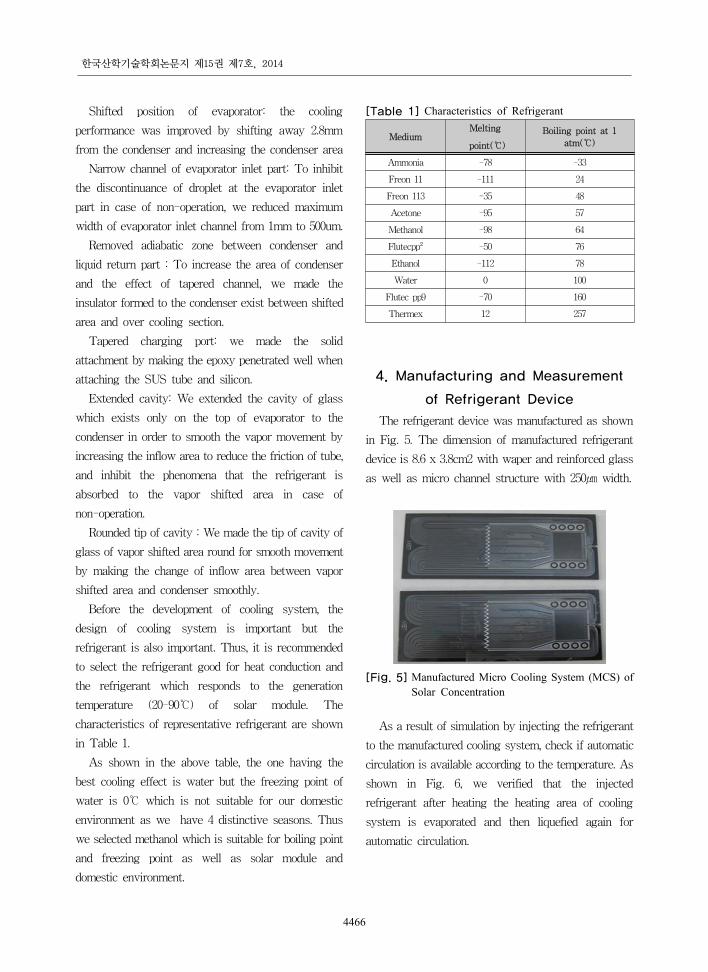
The refrigerant device was manufactured as shown
in Fig. 5. The dimension of manufactured refrigerant
device is 8.6 x 3.8cm2 with waper and reinforced glass
as well as micro channel structure with 250㎛ width.
[Fig. 5] Manufactured Micro Cooling System (MCS) of Solar Concentration
As a result of simulation by injecting the refrigerant
to the manufactured cooling system, check if automatic
circulation is available according to the temperature. As
shown in Fig. 6, we verified that the injected
refrigerant after heating the heating area of cooling
system is evaporated and then liquefied again for
automatic circulation.

Development of Solar Concentrator Cooling System
4467
a)Inject of Refrigerants b)Thermal Test
c)Cooling Test d) Vaporization → liquid[Fig. 6] Verification of Vaporization à Liquefaction
Through Test
As shown in Fig. 7, we put the cooling system on
the test equipment to test max. heat removal capacity.
When the applied heat is TJ=100℃, the heat removal
capacity was 30W(1.67W/cm2) and when TJ=140℃,
max. heat removal capacity was 52W(2.89W/cm2).
[Fig. 7] Cooling System Test
5. Verification Test of Cooling
System
For the test of cooling system, we carried out the
comparison test with 117W solar concentration module
and the module that installed the cooling system to
117W solar concentration module. Fig. 8 as below
shows the solar module with cooling system.
To verify the performance of solar concentrator
module combining the cooling system, we recorded the
temperature and generation capacity of 117W solar
concentration module without cooling system and
117W solar concentration module with cooling system.
Fig. 9 is the graph that compared the generation
capacity according to the time of solar concentration
module without cooling system and the solar
concentration module with cooling system. The circle
symbol in Fig. 9 is a solar concentration module with
cooling system and square symbol is a solar
concentration module without cooling system.
[Fig. 8] Cooling System Combined to 117W Solar Concentration Module
12:00 12:30 13:00 13:30 14:00 14:30 15:00 15:3040
50
60
70
80
90
100
110
120
130
140
150
Out
put p
ower
(W)
Time
w/o cooling system w/ cooling system
[Fig. 9] Comparison of Generation Capacity According to the Time
As verified in the above graph, the difference of
generation capacity of general module and the module
combining the cooling system and solar concentrator
was average 28% in winter. As the test environment
was in winter and the altitude of the sun was low and
the outside temperature was also very low, the

한국산학기술학회논문지 제15권 제7호, 2014
4468
response of the used methanol was slow but the
developed cooling system increased the generation
capacity of solar cell.
6. CONCLUSION
In order to increase the efficiency of solar
concentrator, we designed and manufactured the
cooling system. The features of micro cooling system
(MCS) are a natural circulation method by capillary
force which does not need the external power. By using
the potential heat in case of changing the fluid, it is
available to realize the high performance cooling and by
using the characteristics of high efficient heat delivery
in Micro Channel, it is available to maintain the little
temperature difference (Less than 1°C). In addition, due
to small internal volume, it is not affected by the
gravity and the contact heat resistance can be reduced
remarkably by complete attachment with cooling body.
To verify the performance of solar concentrator
module combining the cooling system, we recorded the
temperature and generation capacity of 117W solar
concentration module without cooling system and
117W solar concentration module with cooling system.
The cooling device is installed in the module's power
output is increased by 28%. Increasing the cooling
efficiency of the photovoltaic device will be proceeded
in future study.
References
[1] Garboushian V. and Gordon, R., “"Optical Design
Considerations for High Concentration Photovoltaics”",
Proc. SPIE Conference 6339, High and Low Concentration
for Solar Electric Applications, pp. 905 - 913, 2006.
DOI: http://dx.doi.org/10.1117/12.679664
[2] Martin A. Green,Keith Emery,Yoshihiro Hishkawa and
Wilhelm Watra, “Solar Cell Efficiency Tables(Version
31),” Prog. Photovolt: Res. AppL, 2008,V01. 16, pp.61 –77
DOI: http://dx.doi.org/10.1002/pip.808
[3] S. Shoji and M. Esashi, 1994, " Microflow Devices and
System," J. Micromesh. Microengin. 4, 157-171.
DOI: http://dx.doi.org/10.1088/0960-1317/4/4/001
[4] M. Elwenspoke, T. J. Lammerink, R. Miyake and J. H. J.
Fluitman, 1994, "Toward Integrated Microliquid handling
Systems," J. Micromesh. Microengin. 4, 227-245.
DOI: http://dx.doi.org/10.1088/0960-1317/4/4/008
[5] G. T. A. Kovacs, 1998, " Micromachined Tranducers
Sourcebook," Mac Graw Hill, Boston, pp. 779-883.
[6] D. jed Harrison, C. Skinner, S. B. Cheng, G. Ocvirk, S.
Attiya, N . Bings, C. Wang, J. Li, P. thibault, and W. Lee,
1999, " From Micro-Motors to micro- Fluidics: the
Blossoming of Micromachining Technologies in
Chemistry, Biochemistry and Biology," Trans 1999, 12-15
[7] Myeonghwan Seo, Yoonsik Kim, Jinwoo Hong, Heejoon
Lee, SangKoo Park and Sunhyung Kim,“ Research of the
PV Tracking System,” journal of the KAIS, Vol. 11, No.
8 pp. 2951-2957, 2010
DOI: http://dx.doi.org/10.5762/KAIS.2010.11.8.2951
HeeJoon Lee [Regular member]
•Feb. 2001 : Department of
Electrical Engineering, Soon-
chunhyang University. (Ph. D.
in Electrical Engineering)
•Mar. 2001 ∼ Sep. 2010 :
Contract Professor, Department
of Electrical Engineering, Soon-
chunhyang University
•Jan. 2011∼current : CEO. Mirtech R&D
<Research Interests>
Renewable, Electrical machines
Gueesoo Cha [Regular member]
•Feb. 1987 : Department of
Electrical Engineering, Seoul
National University. (Ph. D. in
Electrical Engineering)
•Sep. 2004 ∼ Aug. 2005 : Visiting
professor of MIT
•Mar. 1987 ∼ current : Professor,
Department of Electrical
Engineering, Soon- chunhyang
University
<Research Interests>
Energy conversion device, Superconducting machines