development of self-centering earthquake resisting systems · 13th world conference on earthquake...
TRANSCRIPT
13th World Conference on Earthquake Engineering Vancouver, B.C., Canada
August 1-6, 2004 Paper No. 3393
DEVELOPMENT OF SELF-CENTERING EARTHQUAKE RESISTING SYSTEMS
Andre FILIATRAULT1, Jose RESTREPO2 and Constantin CHRISTOPOULOS3
SUMMARY With current seismic design approaches, most structural systems are designed to respond beyond the elastic limit and eventually to develop a mechanism involving ductile inelastic response in specific regions of the structural system. Although seismic design aimed at inelastic response is very appealing, particularly from the initial cost stand point, regions in the lateral force resisting system are expected to be damaged and might require repair in moderately strong earthquakes. Furthermore, the structure may be damaged beyond repair in strong earthquakes and may exhibit excessive deformation in moderately large earthquakes. These issues have led to the development in recent years of structural systems that possess self-centering characteristics and that are economically viable alternatives to current lateral force resisting systems. These new structural systems incorporate the nonlinear characteristics of yielding structures and encompass self-centering properties allowing the structure to return to its original position after an earthquake. The main objective of this paper is to briefly describe some of these self-centering structural systems.
INTRODUCTION
The cost associated with the loss of business operation, damage to structural and non-structural components following a moderately strong earthquake can be significant to modern society. Such cost is often comparable, if not greater, to the cost of the structure itself. With current design approaches, most structural systems are designed to respond beyond the elastic limit and eventually to develop a mechanism involving ductile inelastic response in specific regions of the structural system. For this reason, these regions are especially detailed for ductility and for energy dissipation.
Figure 1 shows the idealized force-displacement response of a linear elastic system and of a system representing a yielding structure of equal initial stiffness and mass. The maximum seismic force induced in the yielding system is significantly lower than that of the linear elastic system. The maximum
1Department of Civil, Structural and Environmental Engineering, State University of New York, Buffalo, NY 14260, USA 2Department of Structural Engineering, University of California, San Diego, La Jolla, CA, 92093, USA 3Department of Civil Engineering, University of Toronto, Toronto, Ontario, M5S 1A4, Canada
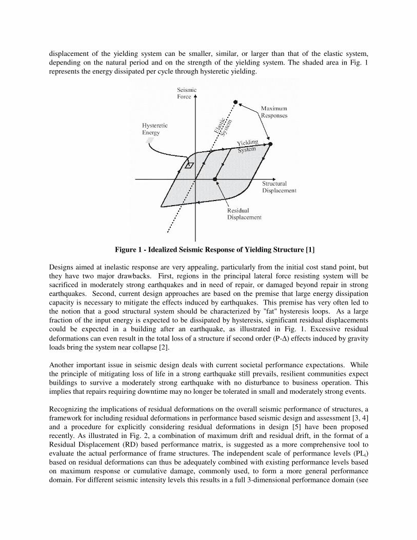
displacement of the yielding system can be smaller, similar, or larger than that of the elastic system, depending on the natural period and on the strength of the yielding system. The shaded area in Fig. 1 represents the energy dissipated per cycle through hysteretic yielding.
Figure 1 - Idealized Seismic Response of Yielding Structure [1]
Designs aimed at inelastic response are very appealing, particularly from the initial cost stand point, but they have two major drawbacks. First, regions in the principal lateral force resisting system will be sacrificed in moderately strong earthquakes and in need of repair, or damaged beyond repair in strong earthquakes. Second, current design approaches are based on the premise that large energy dissipation capacity is necessary to mitigate the effects induced by earthquakes. This premise has very often led to the notion that a good structural system should be characterized by "fat" hysteresis loops. As a large fraction of the input energy is expected to be dissipated by hysteresis, significant residual displacements could be expected in a building after an earthquake, as illustrated in Fig. 1. Excessive residual deformations can even result in the total loss of a structure if second order (P-∆) effects induced by gravity loads bring the system near collapse [2]. Another important issue in seismic design deals with current societal performance expectations. While the principle of mitigating loss of life in a strong earthquake still prevails, resilient communities expect buildings to survive a moderately strong earthquake with no disturbance to business operation. This implies that repairs requiring downtime may no longer be tolerated in small and moderately strong events. Recognizing the implications of residual deformations on the overall seismic performance of structures, a framework for including residual deformations in performance based seismic design and assessment [3, 4] and a procedure for explicitly considering residual deformations in design [5] have been proposed recently. As illustrated in Fig. 2, a combination of maximum drift and residual drift, in the format of a Residual Displacement (RD) based performance matrix, is suggested as a more comprehensive tool to evaluate the actual performance of frame structures. The independent scale of performance levels (PLi) based on residual deformations can thus be adequately combined with existing performance levels based on maximum response or cumulative damage, commonly used, to form a more general performance domain. For different seismic intensity levels this results in a full 3-dimensional performance domain (see
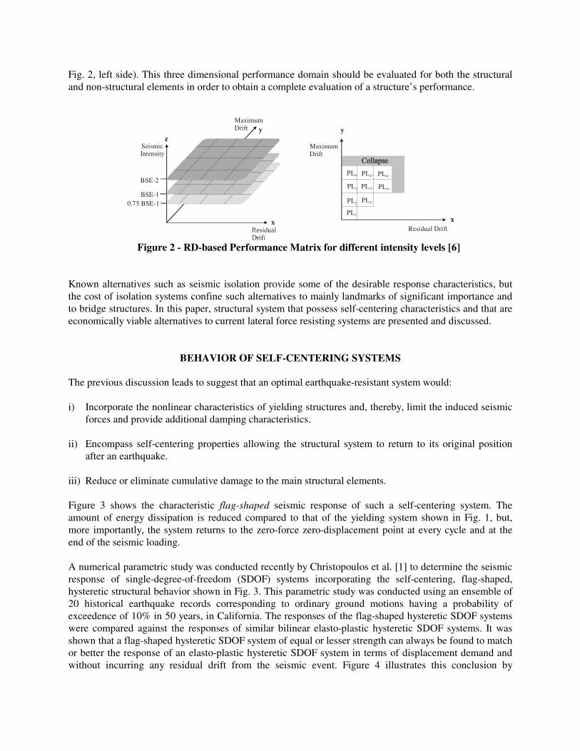
Fig. 2, left side). This three dimensional performance domain should be evaluated for both the structural and non-structural elements in order to obtain a complete evaluation of a structure’s performance.
Maximum Drift
Residual Driftx
y
PL1
PL2
PL3
PL4 PL4* PL4*
PL3* PL4*
PL2*
Maximum Drift
Seismic Intensity
x
y
BSE-1
BSE-2
0.75 BSE-1
Figure 2 - RD-based Performance Matrix for different intensity levels [6]
Known alternatives such as seismic isolation provide some of the desirable response characteristics, but the cost of isolation systems confine such alternatives to mainly landmarks of significant importance and to bridge structures. In this paper, structural system that possess self-centering characteristics and that are economically viable alternatives to current lateral force resisting systems are presented and discussed.
BEHAVIOR OF SELF-CENTERING SYSTEMS The previous discussion leads to suggest that an optimal earthquake-resistant system would: i) Incorporate the nonlinear characteristics of yielding structures and, thereby, limit the induced seismic
forces and provide additional damping characteristics. ii) Encompass self-centering properties allowing the structural system to return to its original position
after an earthquake. iii) Reduce or eliminate cumulative damage to the main structural elements. Figure 3 shows the characteristic flag-shaped seismic response of such a self-centering system. The amount of energy dissipation is reduced compared to that of the yielding system shown in Fig. 1, but, more importantly, the system returns to the zero-force zero-displacement point at every cycle and at the end of the seismic loading. A numerical parametric study was conducted recently by Christopoulos et al. [1] to determine the seismic response of single-degree-of-freedom (SDOF) systems incorporating the self-centering, flag-shaped, hysteretic structural behavior shown in Fig. 3. This parametric study was conducted using an ensemble of 20 historical earthquake records corresponding to ordinary ground motions having a probability of exceedence of 10% in 50 years, in California. The responses of the flag-shaped hysteretic SDOF systems were compared against the responses of similar bilinear elasto-plastic hysteretic SDOF systems. It was shown that a flag-shaped hysteretic SDOF system of equal or lesser strength can always be found to match or better the response of an elasto-plastic hysteretic SDOF system in terms of displacement demand and without incurring any residual drift from the seismic event. Figure 4 illustrates this conclusion by

presenting the time-histories of displacement, acceleration, absorbed energy for an elasto-plastic (EP) system and for a flag-shaped (FS4) system having the same initial natural period and 70% of the yield force of the EP system.
Figure 3 - Idealized Seismic Response of Yielding Structure [1]
The force-displacement responses of both systems are also compared in the figure. Note that the elasto-plastic system deforms inelastically primarily in one direction, while the FS4 system has a similar amount of inelastic excursions in both directions. For the elasto-plastic system, the one-sided inelastic deformations will in fact be accentuated by P-∆ effects [2] that were not taken into account in the study. The FS4 system achieves a smaller maximum displacement than that of the EP system, while the maximum absolute accelerations are similar. The energy absorbed is considerably smaller for the FS4 system. Finally, unlike the EP system that sustains a residual displacement, the FS4 system returns to its initial zero position after the end of the earthquake.
EARLY APPLICATIONS OF SELF-CENTERING SYSTEMS
The self-centering system discussed above is conceptually similar to the rocking concept combined with energy dissipation devices used in the design of the “stepping” rail bridge over the south Rangitikei River in New Zealand. This bridge, shown in Fig.5, has been in operation since 1981. This railroad bridge is 70 m tall, with six spans of prestressed concrete hollow-box girder, and overall length of 315 m [7]. The base isolation is mainly designed to allow the sideways rocking of pairs of slender reinforced concrete piers. Torsional-beam dampers [8] limit the amount of rocking. Note that the weight of the bridge, which allows its re-centering, is not carried by the dampers, but is transmitted to the foundation through thin laminated-rubber bearings.

Figure 4 –Comparative Seismic Response of Elasto-Plastic (EP) and Flagged-Shaped (FS4) Systems, 130% Loma Prieta (Hollister Differential Array) Record, a) Relative Displacement Time-Histories,
b) Absolute Acceleration Time-Histories, c) Absorbed Energy Time-Histories, and d) Force-Displacement Responses, from Christopoulos et al. [1]
Figure 5 – Early Applications of Self-Centering Systems on the
Rangitikei Railway Bridge in New Zealand [9]
RECENT DEVELOPMENT OF SELF-CENTERING SYSTEMS Self-Centering Systems for Reinforced Concrete Structures Priestley and Tao [10] proposed the use of self-centering precast concrete moment resisting frame systems prestressed with partially unbonded tendons as the primary lateral force resisting systems in seismically prone areas. MacRae and Priestley [11] and Stanton et al. [12] subsequently carried out experimental work on precast beam-column subassemblies. Stanton et al. [12] proposed a hybrid system, in which mild steel reinforcement was combined with unbonded tendons in the critical connections. The objective of using mild steel reinforcement was to provide hysteretic energy dissipation to the system.

The similar self-centering concept was used by Stanton and Nakaki [13] in the development of the post-tensioned split rocking wall system, as shown in Fig. 6. In this system, wall panels are split to allow rocking of the individual panels about their individual bases. The weight of the panels provides re-centering forces. If the weight is not sufficient to completely re-center the wall panels, unbonded post-tensioning tendons connecting the wall to its foundation can be installed. Energy dissipation can be introduced by grouting reinforcing bars into vertical ducts at the edges of the wall, so that they yield cyclically in tension and compression during an earthquake. An alternative is to place ductile shear connectors between the wall panels, which deform cyclically in shear as the walls rock back and forth.
Figure 6 – Post-Tensioned Rocking Wall System [13] Several self-centering systems have been studied as part of the co-coordinated four-phase PRESSS research program on precast concrete systems in the United States. This program culminated with the testing of a 60% scale five-story building [14, 15]. This building included precast prestressed concrete frames with partially debonded tendons in one direction and a coupled wall designed to provide lateral force resistance in the other loading direction. U-shaped rolling stainless steel plates, as shown in Fig. 7, were designed for energy dissipation and used to couple the walls.
Figure 7 – Yielding U-Shaped Rolling Steel Plates for Coupled Reinforced Concrete Walls [16]
The building was tested with the pseudo-dynamic method under several different earthquake ground motions of different amplitudes. Under the largest motion (1.5 times UBC Zone 4 loading), the wall direction experienced a peak drift of 2.9%, yet returned to only 0.055% drift at the end of the motion. Damage during testing in the wall direction was limited to the loss of two pieces of cover, one at each end of the wall, approximately the size of a human hand. The structure would have been ready for immediate occupancy after the earthquake. In the frame direction, the design drift of 2% under the design earthquake was achieved with no visible damage. The frame was then displaced to 4% roof drift to investigate its deformation capacity under extreme overload conditions. The hybrid frame performed extremely well, as shown in Fig.8, suffering

only the initiation of minor spalling of the top and bottom beam cover adjacent to the beam-column interface. The other cracks that formed were hairline, and they all closed when the load was removed.
Figure 8 – Hybrid Connection of Five-Story PRESSS Building at 4% Drift Ratio [17]
Restrepo [9] further extended the self-centering concept proposed by Stanton to reinforced concrete cantilever walls by using a wall system prestressed with unbonded tendons and conventional reinforcement for energy dissipation, as shown in Fig. 9. The main advantages of this hybrid jointed wall systems are the large lateral displacement capacity, the lack of structural damage associated with large displacements and the ability to return to the original position upon unloading. Results from non-linear time history dynamic analyses indicate that the dynamic response of hybrid wall systems, as reflected by the bending moment and shear force envelopes, is similar to that of conventional monolithic wall systems. Quasi-static and shake table experimental work have clearly shown the benefit of jointed systems [9, 18]. Figure 10 shows the hysteretic response obtained from a hybrid wall unit. The hysteretic energy dissipation provided by the axial energy dissipators is evident in the lateral force-lateral drift response. No strength degradation occurred below 3% drift. The prestressing strands, together with the gravity loading, provided a restoring force so the wall always returned to its original position. After the tendons exceeded the yield limit, some residual drift was observed. The apparent loss of stiffness that is observed at large drift levels was mainly due to irrecoverable compressive strains developed in the confined concrete at the wall toes.
The extent of concrete cracking and spalling in a hybrid wall panel at a drift level of 4% is illustrated in Fig. 11. Cosmetic spalling of the concrete took place vertically and horizontally. A network of very small width cracks developed on both faces of the wall through the anchorage length of the bars used for energy dissipation.
The self-centering concept has also been extended to other types of reinforced concrete structures, including concrete coupled walls [19] and cantilever walls with vertical joints [20]. Kurama and Shen [21] proposed a new type of hybrid coupled wall system in which coupling of concrete walls is achieved by post-tensioning steel beams to the walls using unbonded post-tensioning tendons. Results of analytical and experimental studies indicated that post-tensioned hybrid coupled walls with initial stiffness similar to

walls with embedded steel coupling beams can be designed to provide stable lateral strength levels at large cyclic inelastic deformations. Furthermore, the post-tensioned steel beams provide a significant restoring force to the walls, thereby reducing residual lateral displacements.
Figure 9 – Hybrid Reinforced Concrete Cantilever Wall System [9]
Figure 10 – Hysteretic Response of Hybrid Reinforced Concrete Cantilever Wall System [9]

Figure 11 – Damage to Reinforced Concrete Cantilever Wall System at 4% Drift Ratio [9]
Self-centering Systems for Confined Masonry Walls Toranzo et al. [22, 23] proposed the use of self-centering systems for use in conjunction with traditional methods of construction in developing nations. It was suggested to use rocking confined-masonry systems incorporating low-cost external hysteretic energy dissipation devices. Proof-of-concept shake table testing was conducted on a 40% scale three-storey hybrid wall unit. The wall unit in this test was built with brick masonry infill, and included the slabs, as shown in Fig. 12. The columns were designed for strain control to ensure small shear distortions would occur in the wall panel, while the wall rocked at the foundation. Energy dissipation devices, in the way of tapered levers designed to yield in bending with constant curvature, were installed at the wall toes, as shown in Fig. 13. This test unit was subjected to 60 dynamic tests on the 200 KN capacity shake table at the University of Canterbury, New Zealand. Figure 14 shows the response of the unit under the Taft N21E record of the 1952 Kern County earthquake record magnified to attain a target peak ground acceleration of 0.5g. The seismic response of this unit was excellent. The masonry infill maintained its integrity throughout. No cracking was observed to occur in the infill. The maximum residual drift of 0.13% was observed after an excursion to 1.8% drift. The residual drifts were due to the spreading of yield lines in the slabs. Self-Centering Systems for Steel Structures Recently, self-centering systems have been proposed for steel framed structures by Ricles et al. [24] and Christopoulos et al. [6], [25]. Figure 15 illustrates the hybrid post-tensioned connection developed by Ricles et al. [24] for steel moment-resisting frames (MRF). This connection consists of high strength steel strands that run along side the web of the beam and anchor to the exterior column flange at the end of the frame. In addition, seat and top angles are bolted to both column and beam. Shear resistance is provided by a combination of friction at the beam-column interface and also by the steel angles. The system is designed so that the steel angles are the only yielding elements. Therefore, only the steel angles would need to be replaced after a major earthquake. Additional benefits of this connection include i) no field welding required, ii) use of conventional materials and skills, and iii) similar initial stiffness to conventional welded connections.

Figure 12 - Rocking Confined Masonry Systems on Shake table [22, 23]
foundation beam
rocking wall
dissipator-end connected to the wall throught pin
dissipator-end fixed to foundation through bracket
brackets fixed to foundation
Figure 13 - Flexural Energy Dissipation Devices for Rocking Confined Masonry Systems [22, 23]
-60
-40
-20
0
20
40
60
-2 -1 0 1 2
Roof drift, %
Bas
e m
om
ent,
kN-m
Run 41 – 2.83 x Taft
-60
-40
-20
0
20
40
60
-2 -1 0 1 2
Roof drift, %
Bas
e m
om
ent,
kN-m
Run 41 – 2.83 x Taft
Figure 14 – Dynamic Base Moment-Drift Response for Amplified Taft Earthquake Record [22, 23]
shake table
4585
3980
1260
1260
1260
200
130 580 130
120 470 840 470 120

Figure 15 - Hybrid Post-Tensioned Connection for Steel Frames [24]
Figure 16 shows a photograph of a Post-Tensioned Energy Dissipating (PTED) steel frame concept proposed by Christopoulos et al. [6], [25]. The post-tensioning (PT) force is provided at each floor by high strength bars or tendons located at mid-depth of the beam. Four symmetrically placed energy-dissipating (ED) bars are also included at each connection to provide energy dissipation under cyclic loading. These ED bars are threaded into couplers which are welded to the inside face of the beam flanges and of the continuity plates in the column for exterior connections and to the inside face of adjacent beam flanges for interior connections. Holes are introduced in the column flanges to accommodate the PT and ED bars. To prevent the ED bars from buckling in compression under cyclic inelastic loading, they are inserted into confining steel sleeves that are welded to the beam flanges for exterior connections and to the column continuity plates for interior connections. The ED bars are initially stress-free since they are introduced into the connection after the application of the PT force.
PT Bar
ED Bar
ED Bar
Couplers Sleeves
Shear Tab
Figure 16 – PTED Connection for Steel Frames [1], [25]

The proposed PTED connection relies on the PT force to maintain contact between the beams and columns. Horizontally slotted shear tabs are welded to the column flanges and bolted to the beam web to provide stability during construction, and to insure an alternative vertical shear transfer mechanism from the beam to the column. The slots in the tabs allow the free opening and closing of the gap at the beam-to-column interface. Nonlinear elastic action is introduced by gap openings at each beam-to-column interface. Inelastic action takes place through yielding of the ED bars once the gap is opened. Quasi-static testing was conducted on a large-scale exterior beam-to-column PTED connection by Christopoulos et al. [6], [25]. The results of the tests show that the PTED test specimen was able to undergo large inelastic deformations without any damage in the beam or column and without residual drift. An experimental study was also conducted on a half-scale steel moment-resisting frame assembly incorporating two exterior and one interior PTED connections along with a concrete floor slab [6, 26]. As illustrated in Fig. 17, the PTED test frame was able to deform up to 3% inter-story drift without major damage occurring to the primary steel members, while retaining its self-centering capabilities. The presence of the floor slab and gravity loads did not inhibit the performance of the PTED test frame. Cracking patterns in the floor slab were uniform and consistent, as shown in Fig. 18 for a 3-colum and 3-beam assembly. While the presence of the floor slab produced larger values of initial stiffness, its influence diminished as the inter-story drift increased.
Figure 17 – Interstorey Shear -Drift Response of PTED Test Frame [6]
Self-Centering Systems for Bridge Structures Since the early applications of self-centering concept to the Rangitikei river bridge in New Zealand, Mander and Cheng [27] carried out experimental work to evaluate the response of systems incorporating unbonded prestressing in bridge piers. Xu and Tsopelas [28] proposed a self-centering base isolation system for bridge structures that consists of flat sliding bearings and precise positioning fluid dampers. The liquid-spring damper consists of a single column of pressurized compressive fluid. The orificing of the fluid body through the piston rod provides the damping characteristics of the system. The precise positioning mechanism uses a neutral position that is rigid before and after a shock. The piston rod is displaced at its limit position because of the pre-compression of the fluid column. A mechanical configuration that compresses the fluid body, whichever the direction of movement of the piston rod is, ensures the repositioning of the rod to its neutral position after a shock has been damped. Precise positioning fluid dampers could be designed to eliminate any permanent displacement especially for isolation systems that lack adequate post-yielding stiffness characteristics.

Primary Crack
SecondaryCrack
LongitudinalCrack
Plan View
Figure 18 – Cracking Pattern in the Floor Slab of a PTED Frame Assembly [27]
CONCLUSIONS This paper briefly described the behavioral concepts and practical developments of a new generation of economically viable self-centering earthquake-resistant structural systems. The main advantages of these systems are their large lateral displacement capacity, the lack of structural damage associated with large displacements and their ability to return to the original position upon unloading.
REFERENCES
1. Christopoulos, C., Filiatrault, A., and Folz, B. “Seismic Response of Self-Centering Hysteretic SDOF
Systems,” Earthquake Engineering & Structural Dynamics, 2002, 31(5): 1131-1150. 2. MacRae GA, Kawashima K. “Post-Earthquake Residual Displacements of Bilinear Oscillators,”
Earthquake Engineering and Structural Dynamics, 1997, 26: 701-716. 3. Christopoulos, C., Pampanin, S. and Priestley, M.J.N. “New Damage Index for Framed Systems
Based on Residual Deformations: Part I”, Journal of Earthquake Engineering, 2003, 7(1), 97-118. 4. Pampanin, S., Christopoulos, C. and Priestley, M.J.N. “New Damage Index for Framed Systems
Based on Residual Deformations: Part II”, Journal of Earthquake Engineering, 2003, 7(1), 119-140. 5. Christopoulos, C., and Pampanin, S. “Towards Performance-Based Design of MDOF Structures with
Explicit Consideration of Residual Deformations”, Invited paper, ISET Journal of Earthquake Technology, Special Issue on Performance-Based Design, 2004, (in press).
6. Christopoulos, C., Filiatrault, A. and Uang, C-M. “Self-Centering Post-Tensioned Energy Dissipating (PTED) Steel Frames for Seismic Regions,” Structural Systems Research Project Report No. SSRP-2002/06, Department of Structural Engineering, University of California, San Diego, La Jolla, CA, 2002b: 292 p.
7. Cormack, L.G. “The Design and Construction of the Major Bridges on the Mangaweka Rail Deviation”, 1988, Transaction of the Institute of Professional Engineers of New Zealand, 15:16-23.
8. Skinner, R.I., Robinson, W.H., and McVerry, G.H. “An Introduction to Seismic Isolation”, John Wiley & Sons, New York, 1993. Restrepo, J.I. 2002. “New Generation of Earthquake Resisting Systems,” Proceedings, The first FIB Congress, Federation International du Béton, Paper E-268, Osaka, Japan.
9. Restrepo, J.I. “New Generation of Earthquake Resisting Systems,” Proceedings, The first FIB Congress, Federation International du Béton, Paper E-268, Osaka, Japan, 2002.
10. Priestley, M.J.N. and Tao, J.R.T. “Seismic Response of Precast Prestressed Concrete Frames with Partially Debonded Tendons,” PCI Journal, 1993, 38(1): 58-69.
11. MacRae, G.A. and Priestley, M.J.N. “Precast Post-Tensioned Ungrouted Concrete Beam-Column Subassemblage Tests,” Report No. SSRP-94/10, Department of Applied Mechanics and Engineering Sciences, University of California, San Diego, 1994.
12. Stanton, J., Stone, W. and Cheok, G.S. “A Hybrid Reinforced Precast Frame for Seismic Regions,” PCI Journal, 1993, 42(2): 20-32.
13. Stanton, J.F. and Nakaki, S.D. “Design Guidelines for Precast Concrete Structural Systems”. PRESSS Report No. 01/03-09, 2002, (Available from PCI).
14. Nakaki, S.D., Stanton, J.F. and Sritharan, S. 1999. “An Overview of the PRESSS Five-Story Precast Test Building,” PCI Journal, Vol. 44, No. 2, 26-39.
15. Priestley, M.J.N., Sritharan, S., Conley, J.R. and Pampanin, S. 1999. “Preliminary Results and Conclusions from the PRESSS Five-Story Precast Concrete Test Building. PCI Journal, Vol. 44, No. 6, 42-67.
16. Stanton, J. “Self-Centering Structures for use in Seismic Regions.” Proceedings of the ASCE Structures Congress, Seattle, WA, 2003, Paper No. 622, 8 p. on CD-ROM.
17. Pampanin, S., Priestley, M.J.N. and Sritharan, S. “Frame Direction Modeling of Five-Story PRESSS Precast Test Building,” Report No. SSRP 99/20, University of California, San Diego, 2000.
18. Holden, T, Restrepo, J.I. and Mander, J.B. “Seismic Response of Precast Reinforced and Prestressed Concrete Walls”, ASCE Journal of Structural Engineering, 2003, 129(3): 286-296.
19. Shen, Q. and Kurama, Y.C. “Lateral Load Behavior of Unbonded Post-tensioned Hybrid Coupled Walls,” Proceedings of the Sixth International Conference on Steel-Concrete Composite Structures, Los Angeles, 2000.
20. Perez, F.J., Pessiki, S. and Sause, R., To be published, “Lateral Load Behavior of Unbonded Post-tensioned Precast Walls with Vertical Joints, PCI Journal.
21. Kurama, Y.C. and Shen, Q. “Posttensioned Hybrid Coupled Walls under Lateral Loads,” ASCE Journal of Structural Engineering, 2004, 130(2): 297-309.
22. Toranzo, L., Restrepo, J.I., Mander, J.B. and Carr, A.J. “Shake-table Testing of Confined Masonry Rocking Walls” Journal of Structural Engineering, ASCE, 2004, (under review).
23. Toranzo, L., Restrepo, J.I., Mander, J.B. and Carr, A.J. “Seismic Design of Rocking Confined Masonry Walls with Hysteretic Energy Dissipators and Shake Table Validation,” Paper #248, 13th World Conference for Earthquake Engineering, 2004, Vancouver, Canada.
24. Ricles, J.M., Sause, R., Garlock and Zhao, C. “Posttensioned Seismic-Resistant Connections for Steel Frames,” ASCE Journal of Structural Engineering, 2001, 127(2): 113-121.
25. Christopoulos, C., Filiatrault, A., Folz, B., and Uang, C-M. “Post-Tensioned Energy Dissipating Connections for Moment-Resisting Steel Frames,” ASCE Journal of Structural Engineering, 2002, 128(9): 1111-1120.

26. Collins, J.H., and Filiatrault, A. “Application of Post-Tensioned Energy Dissipating (PTED) Connections in Steel Moment-Resisting Frames,” Report No. SSRP-2003/05, Department of Structural Engineering, University of California, San Diego, 2003.
27. Mander, J.B. and Cheng, C-T. “Seismic Resistance of Bridge Piers Based on Damage Avoidance Design,” Technical Report NCEER-97-0014, NCEER, Department of Civil and Environmental Engineering, State University of New York at Buffalo, New York, 1997.
28. Xu, D. and Tsopelas, P. “Application of Precise Positioning Fluid Damper on Seismic Isolation Systems for Bridges,” Proceedings of the ASCE Structures Congress, Seattle, WA, 2003, Paper No. 478, 8 p. on CD-ROM.