development of ring-joint flanges for use in the hre-2
TRANSCRIPT

a
0
x
E E
x H
31 U
l I
3-
m

ABS'1RACT ~ ~ ~ ~ ~ ~ ~ ~ ~ . o ~ . . ~ . ~ . ~ ~ ~ ~ ~ ~ ~ o ~ ~ ~ ~ ~ ~ o ~ m ~ ~ ~ ~ ~ ~ ~ ~ ~ . ~ ~ ~ ~ ~ . ~ ~ ~ ~ ~ ~
1 . smmy A.ND CONCISJSIONS ...................................... 2 . FLANGE TESTS .................................................
2.1. Qbjec-tive and Scope .................................... 2.2. Discussion of the Jo in t Studies ........................ 2.3. Flange Test No . 1 ...................................... 2.4. Flange Test No . 2 ......................................
3 . TWlE HU-2 FLANGED JOIWY ...................................... 3.1. Assembly ............................................... 3.2. F l a g e s ................................................ 3.3, Gaskets ................................................ 3.4. Bol t s .................................................. 3.5. FerriAes ............................................... 3.6. Nuts ................................................... 3.7. Metallurgical D i f f i c u l t i e s ............................. 3.8. Corrosion-Resistant Coatings ........................... 3-90 Insulat ion .............................................
4. EXPLEtlIMENTRITJ E Q U I P W T ....................................... 4.1. Extensometers .......................................... 4.2. Flcmge Deflection Meter ................................ 4.3. Leak Detectors ......................................... 4.4. Pitch-Diameter Gages ...................................
5 . AUXILIARY 'TESTS .............................................. 5.1, Furnace Tests .......................................... 5.2. Torque-Load Tests ...................................... 5.3. Chemical Technology Division High-pressure
Flange Tests .......................................... A.C~TOWLEDGrnNT5 ..................................................
V
1
4
4
5
7
10
19
19
20
22
22
26
26
26
29
30
30
30
32
33
35
38
38
39
42
43
45 BJBLZOGWHY .....................................................
iii

Ring- joint, fl<mges were studied- extensively i n thermal--
cycle b e s t s as part of t h e development; work associated with
design of Homogeneous Reactor ErSpcrirncnt No. 2 (iW2-2). T h e
pwpose of t h i s program was to provide c r i t e r i a f o r design, i n s t a l l a t i o n , and operation of j o i n t s that would remain leak-
t i g h t under reac tor operaLirig t,emSeratures and prep ObWC2S. - J o i n t s ranging from 1/2 i n , , 1500 Lb t o LI. i n . , 2500 1% and
with various i n i t i a l b o l t loadings were cycled bctwcen room temperature and 636OF.
are ma4e up t o KRE-2 standards and specif icat ions, Leak r aks
of less than 0.25 x LOm3 g of water per day per inch of gasket p i t ch diameter can be rout ine ly attained.. Undamaged. gaskets
may be r e i n s t a l l e d o r new gaskets nlay be used with equal
probabi l i ty of achieving acceptable leak rat,es e The system
insta,l-Led i n IW3-2 w a s provided with a high-pressure b u f f e r
system Lo ensixre that -the s i n a l l mount of leakage t o the ce1.l
would be nonradioac Live a
It was demonstrated Lha-t; when j o i n t s
V

D h T E I ~ O P ~ OF RING-JOINT FLANGES FOR USE IN TEE IBE-2
M. I. Emdin I , Spiewak J. N. Robinson
le Summary and Conclusions
A s part of‘ the development work car r ied out i n conjunction with the
design of the ;ERE-2, n number of flange development t e s t s W Y ” ~ conducted
to s tindy the cha rac t e r i s t i c s of r ing- j o in t :~Imges dur-i.n.g thermal-cycling
operation. It was hoped t h a t i n f o r m t i o n from th is piaogrinm would provide c r i t e r i a for desizn, i n s t a l l a t ion , and operation of joint;s whtch would
remain leakt jght over t he range of reac tor operabing tempera’ciwes and
pressmes. Jo in t s ranging in sizc f r o m 7./2 in., 1500 173, -to 4 in., 2500 Ih were cycled be tmea room temperabwe and 636°F under v-ari c ) i x i n i t i a l bolt, laadtngs. Leak r a t e s were observed. 1% was d-emonstrated that when joints
arc3 made up t o €€RE-2 skandards and specif icat ions, leak rates of less ‘chan
0.25 X lom3 g of water per day pcr inch of gasket p i t ch diameter can be
rout inely a t ta ined ,
may be used with equal probabi l i ty of achieving acceptzblc leak rates.
The f langes i n s t a l l e d i n the r e w t o r were provided w i t h a high-pressure
buffer system ( see sec. 2.2.1) Lo ensme tha t LIE smo~ll amount of beakage
t o the cell would be nonradioactive.
Undamaged gaskets may ’oe reinstal.l.cc3. or YEW gaskets
Flange t e s t No. 1 (see GCC. 2.3) demonstrated ‘chat making up i5x-p;-
jo in t Elanges t h a t remain le,aktight during thema1 cycl.ing w a s a problem ~ ~ h i c h required arlditional development work. The t e s t w a s set ixp t o COWL-
pare the perfomance of 1500- avid 25OO-lb Cla-ciges, but i t was irqmssible
Lo keep e i t h e r fl-ange leaktiglib dining themrial cycles a Thermal profiles
f o r the l500-1b f L m g ; e and temperabwe differences for bolt and gasket
with the flange insulatxd and uninsulated were determi-ned during Lhe t e s t . Furnace %ests ( s e e see. 5.1) were conducted to demons-txate the effect
of added resrilieircy i n the bol t ing system i n reducing the S L T ~ S B induced.
by d i f f e r e n t i a l thermal expansion. The increased res i l iency vas ef fec t ive ,
but t he total required r e s i l i ency could not be a t ta ined by reducing the
bolt; shank diameter alone . Thus a supplementary nieeharzisrrt w a s necessitated,
1
and“ f e r ru l e s were ultima-tely used f o r Lhis pixpose.
however, w a s not optiinized. i n t h i s imvestigatjon o r those vhich followed.
The f e r r u l e length,
Flange t e s t No. 2 (see see . 2*4) w a s -the main e f f o r t of the f lange
development program, and during t h i s t e s t datia were aceurndated on the
flanges specifi-ed (see sec. 3) for the €RE-2. It w a s determined tha t ,
f o r t he flange -to remain t i g h t indefinitel.-y i n service, the bol.ts should
be ti&ten.ed i n i t i a l l y t o a load about twice t h a t recormfiend-ed by khe ASPR
code. The tes t dem.onst:ra,ted thai; flanges under sin-nuEated reac tor service
expx-ienced a leak r a t e of less than 0.25 X
inch of gasket p i t ch diameter. It a l s o showed tha-t r ings having a p i t ch diametral mismatch approaching tha t allowed by M A specif ica,f;:i-ons (but
having surface f i n i s h and seating-angle tolerances t o W - 2 specif?..ca-
t i ons woul-d- experience ahou-t the same leak rate. Fixthey -Lest s, with
and- without fe r ru les , showed that .the effect iveness of the ferri;l.l..e s w a s
acceptably close t o the calculated va,l.ines. It was a l so shown that; the
load tha-t r2main.s a f t e r cycling i n a r ing joint o:? the design used- i s
Iirn_jted by the gasket s’r;ress.
g of wa-Ler per day per
Torque-load- t e s t s ( s c e sec (I 5.2) were cond.ucteti t o de-termlime tire
proper torques t o use i n s-txessing reac-tor flange bol.:t;s: a These tes+,s
demonstrated that the b o l t s o:P a given l o t w i l l exhibi-t similar .torqiae-
load r a t i o s , but that d i f f e ren t lots w i l l behave d i f f e ren t ly .
T h e concl-insions dram from the en t i r e program m.ay be su.mmarized :
1, Flanges made inp t o 1~13-2 spec i f ica t ions (see scc. 3 ) rnay be ex-
pected- t o ex-periencc i n i t i a l leak r a t e s of l e s s than 1 x 1_Om3 e; of water
per day per inch of gasket p i t ch diamet,er, dropping t o less than. 0.25 x lom3 g o:P water per da.y a f t e r several cycles. ‘This leak rate, when compensated.
f o r by the use of a buffex- systcrn ( s e e see. 2.2), i s considered. acceptably low f a r flanges in aqmous homogeneous reac- tor s e n i c e e
2. Und..amaged gaskets may be reins’ixlbed or n e w gaskets may be u.sed.
w i t h equal l ikel ihood of achieving an acceptable leak r a t e
3 . %l..anges may be insulated t o rcduce heat I.oss to t h e yeactor cel.1,
without incixr ing excessive leak rates during themal cycling
Closer tolerances on the p i t ch diameter of the flange graave and 4.
of the gasket and. on the contact anglc of the two and f i n e r control of the
2
sixrfaee f i n i s h of the con.tacting surfaces seem Lo enhance the likehihood
of s a t i s f ac to ry f i t u p and the achievement of leaktightness. Un-Lil fu r the r
t e s t s ectabl-ish a definitAve re la t ionship between tolerance and leak r a t e
o r between surface f i n i s h and leak r a t e o r both, 3.L i s recommend-ed t h a t
specificat-ions f o r reactor PI-angcs requisre the closest, tolerances t h a t
have been niet without excessive d i f f i c u l t y by flange and gasket xnanufac-
twc-ers. The specif icat ions given i n Section 3 have been succcssfully
met
5. The flange should be a s hard as possible and the gasket; should
be as soft as possible t o minimize the deformation of the f lange groove
with successive reassemblies and" conseqyently t o extend the service l i f e
of the fl-ange. Limiting hardnesses which have becn successfully met by
f l a x g e and gasket manmfactmrers are given i n Section 3.
6. Care must be taken during manufacture, handling, storage, and
i n s t a l l a t i o n t o prol;ec"r, the seating surfaces of the flange grooves and
of the gasketis from darriage.
it i s ce r t a in ly fi iffi .cult t o put i n t o pract ice . T ' d s i s perhaps an obvious prec,r;tii.tian, but
'9. Roltis should be Lightened t o an initial s t r e s s about twice the
code recommended value
Tlzere is no basis for clzoosirLg between oval and octagonal cross- 8. sect ion gaskets as 8 result of the present program, but the octagonal
gasket i s prefemed becaixe it lend I; i t s e l f t o niore precise m ~ ~ c h h i n g and
inspection and because it sea ts with less p l a s t i c deformation.
9. The use of f e r r u l e s and. reduced-shank b o l t s lowers the s t r e s ses
induced by d i f f e r e n t i a l thermal expansion and thus enhances Lhe prob-
ab:ility of a jo in t remaining leakt ight through many thermal cycles.
LO.
t he joint are believed. t o be limited. by a rnaxirnz;lai gasket corflpressive
stress of about 32 000 gsli (based on the r ing cross-sect ional area paral-
l e l to the face of the :flange) or a maxirium gasket contact stress of
about; 160 000 ps i .
Thc maximum bol t ing loads which may be effectiively applied to
11. Since the maximum bol t ing loads which can be ef fec t ive ly appl-led
t o a flange are limited by the gasket I-oads, it rriay be concluded that
torque wenches are adequately safe for fLeld control of b o l t t ightening.
3
It i s desirable , however, .to determine -the torque-to-load r a t i o foy each
l o t of b o l t s t o effect imifouam h a l t 1"oad.icg and thweby to pYromote leak-
trightmess. The torque-load ca l ib ra t ion can be made r ead i ly in the field.
Both 2500- and 1500-lb f langes appeared .Lo be adequate over the 12.
range of the t e s t s .
13. E d i t m ' s note: As of March 1.961, following 2 1/2 years of se r -
vice, the HRE-2 f langes w e r e s t i l l functioning properly.
of excessive leakage tlixmigh a f lange had- occixrred, as dei;e,&ned by
monitoring the buffer zone between t h e t w o r i n g sea l s .
Not one Ti-nstance
1
2. Flange Tests .*"------.YI
2.1. Objective and Scope
The ob jec-t:ive of t h e flange develmgneent program was -Lo develop mi- ter i -a such khat a mechanicab pipe jo in t could. be r a c k ixp t h a t would ex-
hribit, i n i t i a l l y and through thermal cycles, a s m a l l enough leak. r a t e .to
be accep.La'Dle for aqueous homageneoixs nuclear reactlor service a Nwneroiis
thermal cycles of random length were made from 70 t o 636°F (0- t o 2000-psi..
saLixrateci-steaai presswe ) at; a maximmn r a t e of - 1 0 0 " ~ per hour.
The work reported here w a s l imi ted t o flanged @.pe j o i n t s of t he
t y p e specif ied f o r t he IBN-2, c o n s i - s t k g of s t a i n l e s s s t e e l welding-neck
flanges i n t he s i z e range 1/2 t o 4 i n , , 1500- and 2500-1.3 cla,sses, v i t h
stainless s t e e l r ing- j o in t gaskets and carbon steel- bolts. Since priox'
experience w:i-Lh. t h i s type of j o in t had been somewhat e r r a t i c , the program
w a s direc-Led at developing refinemell-Ls .which would make the jo in t more
r e l i a b l e .
i n Sec-Lion 3.
Detailed. descr ip t ions of the components of t h e jo in t are given
In con;junction with var7i.ous phases of the flange development program,
a I-i teratuye search w a s conducted and per t inent reports were reviewed.
These repor t s are l i s t e d cbronologj..c,alJ-y in t he sRih1--iography.
'J. A. Watts, Operating Experience with the HRT FJ.ange Leak Detector System, from 12-6-57 Through 2-11-59, ORNL CF-59-5-116, May 22, 1959 .

2.2. Discussion of t h e Join% Studies
Some fea tures of the KRE-2 j o j n t s (Fig. 1) deviate f3iaom conventional
usage of ring-ty+pe jo in t s . In order t o ensure against I.eaknge of radio-
ac t ive mater ia l from the reac tor system. i n t o the cell a t the flanged j o in t s
and to provide f o r detectLon of kakage, ihe annular space Inetwcen the
inner and outer sealing surfaces or t he gasket i.s pressuaized with heavy
water a t a pressure g rea t e r than t h a t i n the reactor system.
should. develop across the inner scczl, heavy water w i l l leak i n t o the r e -
ac to r system instead of radioact ive mat,erial. leaking outward- Lo the 3.eak-
de tec tor system. The presence oC such a leak i s indicated by the pressixre
drop occxrring in the hcavy-waker system. Thus it i s necessary f a r the
gasket, t o seal against both the irinez? and the o u k r surfaces of each i"l.nngc
groove. I n conventi-onal usage of ring-type jo in ts , sixch a doinble seal. i _ s
not r e qinired e
I@ R leak
UNCLASSIFIED ORNL-LR- D W G 59781
a o I..T -
FERRULE SPACER-
GASKET-
E AK- D ETECT ION AN NU I
LEAK DE'TEC'IOR TUB
E AK- D ETECT ION AN NU LIJ S
OLE THROUGH
LEAK DE'TEC'IOR TUB
LLI S
JGH
Fig . 1,
5

The fl-anges, as wel-l as t he piping, a re insulated. -to avoid excessive
heat l o s s t o the c e l l , A l l fl..mges i n the process systcrn are made of s t a i n l e s s steel- and- c lampd w i t h carbon s t e e l bo l t s . Di f feyent ia l them.a l
expans:ion of t he d i f f e ren t m t e r i a l s and the ex i s t ing ternperatwe d i f - fereiices can cause p l a s t i c d-efomnation i n the gaskets when. the j o i n t s are
cycled through t h e i r normal te-rrr-erat,i.i.re range a Thus there i s a tendency
t o loosen the jo in t and cause lea,kage. ‘This problem i s p a r t l y a l l ev ia t ed
by ri.n-t;roduci-ng grea’cer resil_ience i n t o the f lange-bolt system to permit
the system -Lo absorb d i f f e r e n t i a l e q a n s t o n elastica.l.l_y w L t h l e s s induced
s t r e s s i n the gasket. Greater r e s i l i ence i s introduced by using long b o l t s
with pipe f e r r u l e s and by machiiiing the shank of t he bolt t o a smaller
diameter. Other me-Lhods, not used i n t he presen-i; invest igat ion, a r e the
placing of Bel-l_eu-ille washers u n d e r t h e head of the bo l t ami couiterboring
o f the f langes for :ferrules t o reduce the c f f ec t tve length over which d i f -
Bcrcnt ia l expansion would OCCUT,
I n HRE-2 service, 2500-lb f langes a r e used a t 2000 p s i and 600°F.
Rating of these f langes a t 600°F i s 4620 psi.
c l a s s are ratmi a t 2770 psri. and therefore would be adequate f o r -this ser -
vice.
although the t h e m a l e q a n s i o n stresses a r e s l i g h t l y grea te r .
Flanges of the 1500-l-b
The 2500-lb design w a s se lected because of i t s greater r i g i d i t y ,
‘The hard.ness of t he s t a i n l e s s s t e e l used. i n %he flanges i s essen-Lially
equal t o .that of the r i n g s ? whereas it i s preferable t o use rings o f ma-
t e r i a l m.u.ch s o f t e r than .the f langes. T o produce a l eak t igh t seal between
t h e ring and t h e groove, it i s necessary P o r p l a s t i c defo-snation t o occur
i n t h e metal. t o s e a l of f f i n e surface i r r e g u l a r i t i e s at, the i n t e r f ace .
If, swing t o the hardness of the r ing and the use of excessive bol:ting loads, the flange grooves a re apprecia,bl.y defamed, it may be dif :e icul t
t o s e a l t he jo in t a f t e r reassembly.
-to exercise care t o a t t a i n a good surface finish on the r ings arzt3. grooves,
t o protect this surface from any mays or scratches, and -to l i m i t bolt
loads -to the lowest values t h a t will effec-L an adequate seal.
Therefore, it i s e s s e n t i a l i n XRX-2
The j o i n t s w i l l have t o be broken and remade from a distance. ‘This
i n t e n s i f i e s the problem. of making a ca re fu l inspec-tion of the flange
6

a
grooves before %he reassembly of a joint; and great1.y increases ihe d i f -
f icu-lty of s u r f ace r epa i r .
2.3. Flange ‘ T e s t No. I..
Flange t e s t loop No. 1 consisted of one p a i r of )+-in., 2500-l’b and.
one pa i r of &-in., 1500-lb stainless steel ring-joint welding-neck flanges
a n d was used €or prelirxdnaxry sLir-dies and for the d.evel-opmcnt of i.nct rJ ,TU-
rnen-t,at;ion to be insed- in flange test ; loop No. 2. The system was %iZled
wit,h water to a predeterrriinetl l eve l and. heaLed t o 636°F (2000 psi) by an
c l e c t r i c lclcfzi;er.
t e n t s ,
Cooling was accoinpl_ishcc3. by blo~~down o f the system con-
Approxirnately four cycles per day could be achieved i n this manner.
The i n i t i a l - t e s t of the flanges vas rnadc w i i h g;ol.d~-pl_ated gaskets.
‘ 1 ’ 1 ~ Iswest bolt load ihat would produce an i n i t i a l seal w a s used on the
theory that with low bo l t loadingj deformation of the p;asket and the ring
groove woul.d_ be LQW andl the jo in t would haw the bes t chance of a long
service l t fe , , Leakage w a s experienced with the first, tl~ermal cycle and
continued Llxoigh su.ccess-ive increases i n bo l t loadtng e Even after the
arigPna1 gaskeLs were replaced with mpl-ated gaskets, it w a s never pos-
sible to t ighten the flanges so t h a t they wou3_d remain l eak t ight t,Woi~gh
a s ign i f i can t numbele of therwial cycles. (The bolt l-oadings used. i n these
t c s t s did not approach thosc f i n a l l y recoxnmended f o r HRE-2 use; also, the :rings and grooves were standxrd commexcial products )
Bolt loads were measured RS t h e system was hydrostat-i..cnl.l-y pressurized
i;o 3000 ps i , an4 I;he b o l t , pressure, and gasket loads f o r the t w o flanges are p lo t ted agai.nst, pressure i n Fig. 2. Since the av:KLabLe gasket, load
is a measure of the a b i l i i y of the jo in t to resis t , Leakage, the curves
i r r d - i c a b e t h a t both the 1500- and 2500-2b flanges appear capab’1.e of load-
ing the gasket sufficiently in Lh? pressure range tested.
In spite of t he inabi- l i ty t o secure leakt ight joints, it w a s decided
to r u n some additional cycles Lo detemnLne the temperature p ro f i l e s i n
the flangzs during, t;herm.al cyc1.ing and t o observe Lhe cf Pect of in su la t ing
the flanges on these prof i les .
rfirie whe%her t h e fJ-.anges i n TIRE-2 should be insulated.
These da%a were to be used to help deter-
7

Figure 3 i s a pl-ot of pipe temperature and gasket-bolt temperature difference against a tjme base f a r t h e four cycles, two w i t h insulaLed
flanges and two wi-th minsula ted flanges
UNCLASSITIEI) ORN L - LR - DWG 5 978 2
420,000
100,000
80,000
- n - 2 60,000 0
40,000
20,000
/ 1500-lb FLANGF L0AD2500-lb FLANGE
-/- / 1500-lb FL4N
RESSURE 2500-lb FLAN
j500-lb FLANGE ON GASKET2500-lb FLANGE
- -~
0 1000 2000 3000 PRESSURE ( p s i )
Fig . 2. Effect of Hydrostatic Pressure on B o l t and a s k e t Loads.
-- C Y C L E 3 1
100 200 300
.* H E A T I N G
T I M E (m in )
It m a y be observed thai, t he re
i s lit tl-e diff erexicc in the
maxi mum gaskel, -bol t temperatixe
difference f o r the fo ix cycl-es,
although the equilibrium tem-
perat ixe diffeyence i s grea te r
f OY" t,he uninsixbatcd cases . Heating r a t e does not seem t o
aff F ~ C L the maxiniuin difference a
Equilibrium temperatvre
profiles determined dming these
t e s t s are presented i n F ig . 4 for the insula,t,ed and minsula,t,ed
conditions of the &-in., 1500-170
U N C L A S S I F I E D O R N L - L R - D W G 5 9 7 8 3
0 50 100 COOLING
GASKET T E M P E R A T U R E ( A S S U M E D E Q U A L TO I N S U L A T E D - P I P E T E M P E R A T U R E
G A S K E T T E M P E R A T U R E M I N U S
BOLT T E M P E R A T U R E
Fig 3. T e m p e r a t ; w e s During Ther?na,l- Cyclimg .
8

flange. An abtempt was mcCle to vary -Lhe heating rates for each pai.r of otherwise i d e n t i c a l cycles, but the wmilable bailer capacity prevented m y significant var i a t ion in the hea-Ling r a t e s f o~p the lzninsu1af;ed flanges ~
UN C L A S S l F l E D O R N L - L R - D W E 59704
- -..._I 336°C
_-_-_-
INSULATED
Fig.
U N I N S U 1- AT E D
4. Steady-State Thermal_ Gradients i n 4 - i z 2 . 1500-lb Flange e
9

2.4* Flange Test No. 2 .____"--
A minltistatisn flange t e s t f a c i l i t y (Fig. 5 ) w a s constructed t o serve
as a general-purpose Lest f a c i l i t y f a r t he inves t iga t ion of piping con-
nec-Lors f o r high-temperature aqueous service. The f ac i l - i t y consisted. of
a natural-canvection tIierulal--cycJ-j_ng loop heated by steam f:rorn a 4 o - k ~ elec-Lric bo i l e r an6 was capable of cycling ~ ' L S e ight Lest s.'iat?ons a t a
rabe of 100°F per horn from 1.7 ps ia aJl; 220°F t o 2,000 p s i a a t 636°F.
f acil-i. by w a s ins tnmented for au.'coi-na,tic cycling, and a3..l.. data, except pin
extensome-ter readings, could be read at t h e contrpol panel.
The
T h e f a c i l i t y w a s i _n i t i a l ly operated -to t e s t the flanged join'cs which
had been specified. ( s e e sec. 3) f o r HRE-2. These j o i n t s were specif ied,
somewhat i n tu~ i t ive ly , on the b a s i s of avari.lab1.e experimental- daka and
experience. EaY1-y operation of the f a c t l i t y (through cycle 43) w a s clouded
by e gpipment and. instrumentat ion d.if f i c u l t i e s a During t l i i s period -the
i n s trwnent systems were improved. and- ~ a l - i b r a ~ t e d . , and the equipmen% w a s alteyeri t o achieve reliable service.
I n ea r ly rms it was s t tempkd t o produce tig;bt seal ing wi-th rimitial
bo l t stresses i n the mnge of 20 000 t o 30 000 p s i . I t was soon apparent
t h a t bol-t lmading w a s reduced following thermal cycling so t h a t re t igh ten-
ing twice was necessary f o r a jo in t *Lo remain l eak t igh t .
1-t w a s finally demonstrated. i n run A (cycles &$ t o 52) t h a t by i n i -
tial.1-y tighten.i.ng the bolts t o a bolt s-tress of about 4-5 000 psi , asym.p-
t o t i c bolt loading of about 30 000 p s i could be obtained following several
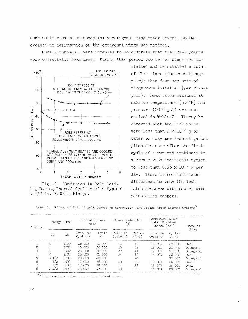
thermal. cycles . Ftglire 6 i l l u s t r a t e s %he var ia t ion tn bo1.t loading as a
t yp ica l 3 l/;,-in., 2500-1'0 f lange was cycI.ed; the b o l t s t ress at room tem-
peratxre w a s observed i n f l ange t e s t No. 2, while the s t x e s s shown i n the
f igu re a t opera"c;ing temperature w a s calculated. The method of' initia1.I.y
o v e ~ s % r e s s i n g the b o l t s i s 1-econmended f o r reac tor service e
It w a s hoped also in run fl t o compare oval ajnd. octagsnal r i ng gask.ets.
No s igni f icant dirlf'e-kence i n asymptotic bol-t loading (Table 1) o r leakage
(Table 2 ) c0u.l-d. be observed beLwecn the two types of gasketss, The f lange grooves showed sl-i-ght, but e s s e n t i a l l y equal, deformation regardless of
-the type of ring used. The observed deforma-Lion of t he oval rings xibas

such as t o produce an essen.t,li.al.l..y octagonal.. r i n g a f t e r several thenn.al
cycI-es; no deformation of -the octagonal. r i ngs w a s noticed. Runs A -t;l-~rough 1 weye intended. t o denmistrate t h a t the €€RE-2 j o i n t s
W ~ I T essentially leak free. During t h i s -period one set of rings was tn-
UN C L A S S I FlED O R N L - L R - D W G 21426
I I I I
BOI-T STRESS AT 0 PER AT I N G T E M PER AT U RE ( 3 3 6 " C 1
FOLLOWING T H E R M A L CYCLING I--,
d IN1 TlAL BOLT LOAD
ROOM TEMPERATURE ( 7 2 ° F ) FOLLOWING THERMAL CYCLING
I
FLANGE ASS E M B ILY t-l E AT t D A N D COOL E D AT A RATE OF 55"C/hr B E T W E E N L I M I T S OF ROOM TEMPERATURE AND PRESSURE AND 336OC AND 2000 psig
0 1 2 3 4 5 6 THERMAL CYCLE NUMBER
Fi.g. 6. Variation i n Bo7.i 1,oacl- i n g Duri-ng Thermal Cycling of a 'Py-pical.~ 3 1J2-i.n 2500-1b Flange a
s.t;alJd. and r e i n s t al-l-ed. a to-Lal
of :Five times (far each. :f~-ange
p a i r ) ; t'izen f a m new s e t s ( : i f
r ings were iiista.l..led- (per :flange
p a i r ) . ~ e a k ra tes measwed a t
~naximim Leirrpeerature (636'F) and
pressure (2000 p s i ) a m sum- marized i n 'l'a'ble 2. It may be
observed that the leak. raiies
were less than 3.. x l.0"3 Q sf
water per day per inch 0% gasket
p i t c h dhme-bei:* a f t e r the f i rs t
cycle of' a. ~u.n and continued t o
decx-ease with ad.ditional- cycles
-Lo l e s s than 0.25 x day. ' l 'he~e is no significant;
difference between t he l.ea.k
r a t e s meaou-ed with new or wi-t;h
r e i n s t a l l e d g!;askei;s a
g per
Tab3 e 1. Effect of Tn i t i a l Bolt Stress on AsyiiipLotic Bo1 t Stress After Thermal Cyclinga
Ini t ia l . S t r e s s S t r e s s Reduction Appa'c'ent Asyf*p- t o t ic Res idual S t r e s s ( p s i ) Type of ( %)
F7-ange Size ( PS i)
-__ Ring __----I_. ~ I-_______
Sta t ion
lb Prior t o Cyc1.e P r i o r t o Cycles P r io r t o Cycles in. Cycle it4 44 Cyc1.e 44 44-48 Cycl..e 44 41+-4.8
7. 2 3 4 5 6 7 8
2 2500 26 000 41 000 41 1 2500 23 000 36 000 20 1 2500 23 000 36 000 27 2 2500 26 000 41 000 34 3 1/2 2500 28 000 42 000
1_/2 1500 17 000 38 000 4 0
3 1/.2 2500 28 000 42 000 L3 1/2 1500 17 000 38 000 24
34 4 1. 41 32 24 32 33 32
1-6 000 27 000 Oval 18 000 21 000 Octagonal 37 000 21 000 Octagonal 16 000 28 000 Ova7
32 000 Octagonal 10 000 26 000 Oval 13 000 25 000 Oval 16 000 28 000 Octagonal
- - - aAl.J. sti-esscs a re based on reduced shank area.
3.. 2

Table 2. Flange Leakage During Therm1 Cyclirig
Leak Bate Pleasured a t 330°C ( g of water ?er day)
Date ( 1 9 5 7 )
RJ3 1/2- in . , 1500-lb 1-in., 2500-lb 2- ln . , 2500-lb 3 1 /2- i f i . , c O L m e E t s 2530-1b Flange Flange Flange
No. 6 Xo. 7 Ro. 2 Eo. 3 Xo. 1 Eo. 4 No. 5 No. 8
Ylaiige
A 3-19 20
4-1
3 4-4 5 6 5
44 1 46 3 52 9
53 i I
55 a'
57 5 6 1 9
x 10-3 x 10-3 2.5 1.32 1.33 0.L6 1.1 0.62
1.44 0.65 1.15 0.54 0.68 0.46 0.72 0.44
x 10-3 x 10-3 x 0.93 1.27 4.3 3.69 0.9L 1.94 0.54 0.73 1.4
0.69 0.85 2.0 0.55 0.74 1.08 3.46 3.74 1.06 0.46 3.59 1.06
x 10-3 6.4 4.7 3.15
2.6 2.74 2.58 2.55
x 10-3 x 10'3 Xew rlngs, HRT 7.4 6.6
5.0 4.6 spec i f i c a t io11 3.4 2.7
2.85 4.04 Re iris t a l l e d 2. $7 3.0 rirLgs, €52 3.2 2.73 2.45 2.36
spec i f i ca t ion
Reins ta l led 12 63 2 0.70 0.34 0.36 0.4'7 0.53 1.5 1.9 2.35 rings, EXT L2 - - ? 64 3 3.63 0.40 3.4 3.54 1.16 1.6 2.04 14 65 4 3.61 0.39 3.39 3.53 1.0 1.6 1.95 2.6 15 66 5 c1.26 9.35 C.37 C.46 0.83 1.3 1.55 1.9
C 4-11 62 - 1.3 0.5; 0.47 0.59 0.97 1.75 2.05 3.25
spec El c a t ion
D 4-18 14 22 23 24 25 26 27 28 29
67 67 47 68 70 7 2 74 7 5 78 80
1 A.
1 1 2 4 6 8 10 12 14
0.3 0.36 3.23 0.54 0.27 0.41 0.42 0.35 0.34 0.33
0.51 0.62 0.34 0.39 0.22 0.27 0.2 3.25 0.14 S.18 3.22 0.26 3.21 0.25 0.19 0.22 0.2 0.23 0.21 0.23
0.66 0.52 0.32 0.28 2.23 0 . 3 0.33 0.27 0.28 0.28
1.55 0.86 0.6 0 .51 0.40 0.59 0.55 0.5 0.5 0.51
1.75 1.4 1.08 1.06 0, 82 1.08 1.27 1.27 1.3 1.32
2.2 14.5 R e i n s t a l l e d 2.1 2.4 r ings , IHRT 1.3 1.7 specification 1.2 1.1 0.89 1.6 i. 3 2.0 1.3 2.4 1.2 2.3 1.3 2.4 1.26 2.5
1.5 5.6 1.1 Reins ta l led 3 8L 3 0.42 0.32 0.75 0.37 0.9 1.15 2.9 2.3 rings, HRT 6 89 s 0.31
17 93 0.75 0.76 0.64 0.8 1.7 2.9 4.3 6.4 20 99 9 0.41 0.43 0.44 0.52 1.08 3.1 2.8 3.3
E 5-2 52 1 0.66 0.43 0.38 0.44 1.3
C.24 0.25 0.3C 2.78 1.4 2.2 1.8 specifica:lon
spec i f ica'; ior, F 5-15 91 1 1.1 1.5 1.15 i. 2 4.1 5.4 7.8 16.9 YJ~w ZiCgS, -3RT
-2 2
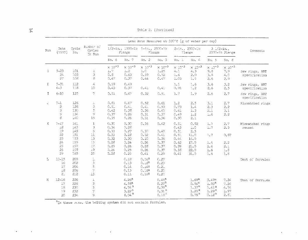
Table 2. (Continuedj
Leak Rate NeasLyed a-t 33Ci"C (g of water per day)
Number of Run Cycles
I n Run
3ate Cycle 1/2-iA1., 1500-,3 1 - i n . , 2530-1b 2- ln . , 2503-10 3 1/2- in . , (1957) xo. Flznge Plsnge Flange 2500-ib Flange C omxe n t s
Eo. 6 No. 7 Eo. 2 Go. 3 T;io. 1 :Vo. 4 KO. 5 no. 8
x 10-3 x 10-3 1.7 1 . 2 0 .8 0.63 0.47 0.37
0.59 0.49 0.43 0.37
3.51 3.47
10-3 1 .0 0.59 0.44
x 10-3 1.25 0.72 0.47
x x 10-3 4 . 1 4 .3 1 .6 2.0 1.03 i. 2
1.1 1.6 0.91 :. 2
1 . 7 1 . 9
- K
x 10-3 >( 10-3 9.8 7.9 3.8 4.3 2.6 2.9
3 .6 3.2 2.6 2.5
2.6 2.7
Z 5-23 24 27
H 5-31 6-3
I 6-10
231 133 10 8
1 3 8 4
10
New r ings , HRT spec i f i c a t lon
112 118
125
Kew rirLgs, E3T s p e c i f l e a t i m 0.41
0.32
0.41
3.51 7 New rings, E3T spec i f l c a t im
J 7-1 2 3 5 8
18 19 22 23 24 25 26 29
K 7-17
L, 10-15 16 17 18 2;
N i2-16 ;7 28 19 20
126 ;2 8 1 3 G '34 i40
I 4 1 L43 145 151 153 155 157 159 165
200 202 204 236 212
226 228 230 232 234
3.81 0.67 0.51 0.4: C. 42 ci. 38 0.37 0.26 C'. 35 0.26
ci. 3c 0.3ci 0.34 0.28 0.33 0.27 0.33 0.28 0.32 3.30 0.28 3.24 3.29 3.26 3.26 3.25 3.28 Ci.25
0.18 0.13 0.14 0.13 0. I1
0.52 3. L " 1 3.36 3.31 3.31
e. 36
0.61 Ci. 50 e. 47 0.37 0.36
0.42
1 .2 2.5 0.73 1.4. 0.6: 1.3 0.49 1 .2 0.50 2. : 0.51 0.92 0.43 1.0 0.51 2.5 0.51 L.0 3.44 14.0 3.62 17.0 0.39 21.0 3.38 22.0 0.41 31.3
3. 1 2.7 2 .3 2.2 2 . 1 3.1 1 .6 2.2
Misnatched rings i
3 5 9
15
1 3 5
11 13 15 17 19 25
1.7 2.7 1 .7 2.3
0.30 CI. 32 0.10 0.26 0.28 0.26 0.41
3. 16a 0.18a 0. i 4 a 2.16a 2.16"
0.4@ 0.4: 3.36 3.37 3.37 3.37 0. 29
0.27 0.23 0.21 0.22 0.2c
0. 49a 0. 27a 0. 39a 3.31 a 0.18
1 . 7 3.87
1 . 4 2.2 1 . 6 2 . 1 1.6 1 . 6 1 .6 1.8
i
3 5 7
13
1 3 5 7 9
Test of f e r r u l e s
4. 26a 4. 58a
3. 23a 4.74"
8.04 a
1. 69a
1.37: 1.20 0. 79a
0. 96a 3.4ga 7.24 1. 939 7.24 l . 4 1 a 4.74 1.29a 1.97 C. l i8a 2.81
T e s t of f e r r u l e s
a, i n these n n s , -5he bolting system dia go-; contain f e r r u l e s .
.
Runs S and K were devoted t o the study of leak rates with flange
grooves <and gaskets having pitch-diameter mismatch grea te r than was per-
mitted by t , ? ~ I3RE-2 specifica,tions and. rmre nearly approaching the mis-
match permitted by ASA B16.20-1956.*
difference i n leakage experience with new or with r e ins t a l l ed gaskets e
I n -t,hese t e s t s the f langes were as:;eniblcd twice with r ings having
Bere again, there w a s no s igni f icant
p i t ch diameters apprsximnately 10 m i l s larger than -the p i tch diameters of
thc f lanze g,?cooves, but t he c loser tolerance on the seating angle and the
sixface f i n i s h was re tained. TJpon disassembly, it was observed t h a t the
p i t ch diameter of the r ings had been reduced Lo a diameter very cl-ose bo Lhat of the flange grooves. When the imposed deforniation and the res idua l
deformation (s-umrriarized i n Table 3) axe p lo t ted on a compressive stress- s t r a i n diagram for s t a i n l e s s s t ee l , they indicate that, a. r ing crushed to
the contour of the flange groove would exhibi t a, res idua l defozmation very
close to that measursed. It w a s a l so observed t h a t the bolts re tained l e s s
of t h e i r i n i t i a l Loading with the mismatched gaskets than with the close-
tolerance gaskets *
Leak r a t e s at; tempcratwe and precsi_;lrc f o r t h i s series ( runs 5 arid
K ) <we swnmarized- i n Table 2. f a r a, 2-in., 25OO-lb flange:, there i s no s igni f icant difference between
the leak r a t e s rncaswed f o r zizismatched gaske Ls and close- tolerance gaskets.
The exception was a 2-in. fltmge which exhibited a leak r a t e %hat increased
with cycling.
there any explamtion for t h i s inconsis tent behavior.
With the exception of one group of data
No defect w a s observed i n the gasket; on disassembly, o r i s
The general conclusion drawn fror-n these test,s is t h a t i n a radi-oactive
environment it i s b e t t e r to procm-c gaskets t o close tolerance than t o
deperid 0x1 in-place forging. The b e t t e r i i i i t ial f i t u p achieved by con-
t r o l l i n g pitch diameter, surface f in i sh , a n d seating-angle tolerance s re - s u l t s i n more consis tent performance of joint components and greaLer r e -
l i a b i l i t y i n r e x Lor service.
R u n s L and M were devoted t o a study of the effect iveness of f e r ru l e s in reducing the thermal bolt; stress induced by d i f f e r e n t i a l expa,n.si.on of
&A 5316.20 (L95G), Ring Soi.n.Z; Gaskets a n d Grocaves
1 5

..
.
r-4 u3
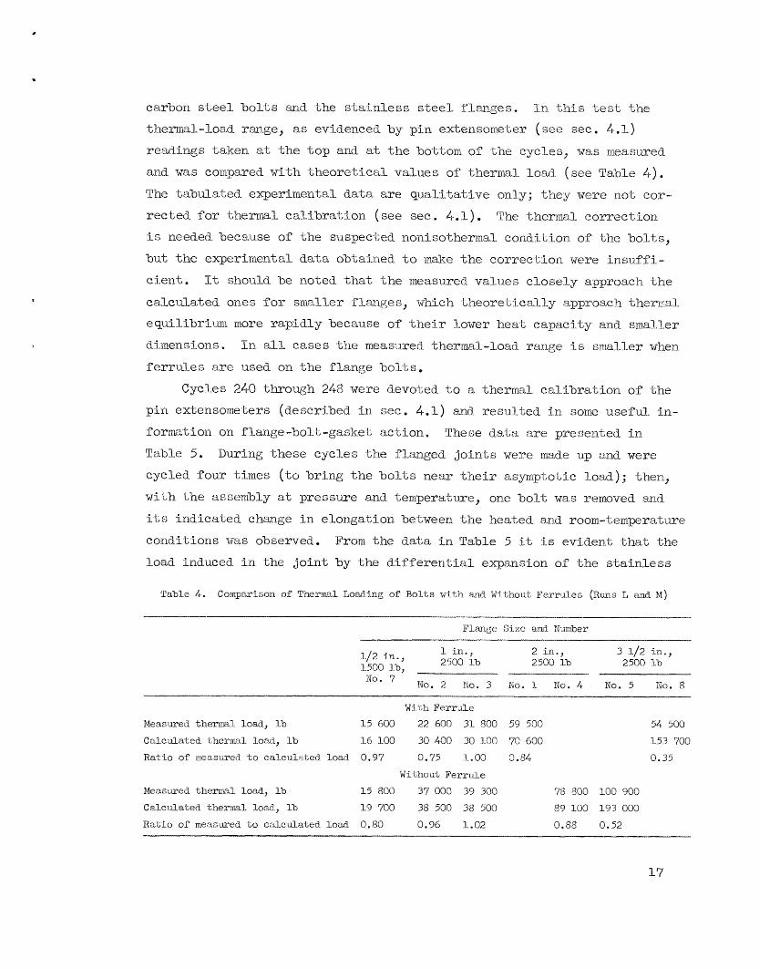
ca.rbon s t e e l b o l t s and the stai.nless steel. flanges, Tn t h i s t e s t Yne
tl:lemal-load ~ m g e , as evidenced by pin extensorieter ( see see. 4.1) readings taken at t he t o p and at t he bot-torn of the cycles, was measured-
and was compared with theoretical values of thermal. Load ( s e e Ta,ble A ) .
The "cibi i l -akd- experimental data are qual i ta t ive onl-y; they were not; cor-
rected for 'c'iiermal. calibration ( see see. 4.1). TIE %hermadl correctLon i s needed because of the suspec%ed nonisathemsl condi-Lion of the bol t s ,
hut t he experirficntal data obtained t o make the correction were i n m f f i -
c i en t .
calculated ones f o r snialler flanges, which Lheoret Lca1.l-y a-pproach thermal.. equilibri-um more rapidly because of their? lower heat capacity and sml l e r
dimensions e I n a l l cases t h e measmecf. thermal-load range i s srna7.ler when
ferrules arc used on the flange bolt,s,
It should be noted t h a t the measured values closely approach the
Cycles 240 through 248 were devoted t o a thermal cal_i'kratj-on of the
pin extensowtebers (described i n see. 4.1) and resi~l-ted in sam useful. i n - formation on f 1-ange -bo1 t, -gasket action *
Table 5.
cycled four times ( t o bring the b o l t s near t h e i r asymptotic load.); then,
wlth the assembly a t pressure and temperature, one boll; was removed and
i t l$ indicated change i n elongation he tween t h e heated. and room-Leinperature
conditions was observed. From the data i n Table 5 it is evident; that the
load induced i n the jo in t by the differeribial expansion of the stainless
The die dal.,a are presented i n
I)ux.ing these cyc7-es the fl.rznged jo in t s were made up and were
T a b l e 4 . Comparison of Thermal TJoadhg of Bolts with m d Without Vcrru1.e~ ( R u n s I, and M)
Flmge S i z e and Number
1 in., 2 in., 3 1/2 i n . , 2500 lb 2500 lb 2500 1% 1/2 in.,
1500 lb, n r ,--, 1\10. ,( No. 2 No. 3 No. 3- No. 4 No. 5 no. 8
Wi 1,Ii Ferrule Measured themrm1 load, lb 15 600 22 600 31- 800 59 500 54 500
Calculated therrml load, lb 1-6 100 30 400 30 100 70 600 153 700
Ratio of rxeaswed t o calculated load. 0.97 0.75 1.00 0.84- 0.35
Without Ferr~i!.e
Measvred themal lo'ad, lb 15 800 37 000 39 300 7 8 800 100 900
Calciilated therrml load, lb 17 700 38 500 38 500 89 100 193 000
R a t i o of measured t o cal-culated load 0.80 0.96 1.02 0.88 0.52
17

.
0
000
000
00 0
00 0
mo
o
0 0
in
00
00
00
Od
x,
7
in F
m
0
00
rl
om
0
0
000
oo
m
rr
h
. \.a F
cr
l 00 0 0
c- 0 c3
i? 0
--SSOI avo1 I
5 h
.d 0
d

,
s k e l f lange and the carbon s t e e l bo l t ing is very close t o the calciil-ated valnc. ( In the calcinlation the flange i s assumed t o be inf ini te l -y x5.gid,
s-ince the reduction i n load Lhat may be expected from f l e x i b i l i i y of the
flange i s a very smal-1 arriount . ) It i s a l so evident t h a t an apprt ac -L : able percentage of the imposed load ( i n i t i a l load -+ thermal load) i s l o s t during
the Cycling, Since the gasket s t r e s ses (contact stress ~~nr3. compressive
stress) corresponding t o the asymptotic b o l t load (at temperature, mens-
ixed when the b o l t w a s removed) is a,lmost constant f o r all. s i ze s a id con-
d i t i ons of flanges, it may be surmised t h a t the maximum load Lhe jo in t
can withstand i s l imited by the gasket Stresses . This surmise could be
establ ished by addi t ional tes t ing a t higher i n i t i a l . load.
3. The €BE-2 Flanged Jo in t
3. I . Assembly
The b o l t s on the €BE-2 flanged Saints are t ightened as indicated i n
Table 6, with every precaution being taken bo protect the gasket and r ing-
groove surfaces from damage during the process.
with a torque wrench, to approximately the torques given i n Table 6, the
TioLts being t ightened i n increments o f the specif ied torque and in a,
The bolts adre tensioned,
Table 6. Bolt-Tightening Specifications f o r IRE-2
__
Flange S i z e Bolting Ring
S i z e S i z e ( in . ) in. 1b No.
Approximate Total Torque Bolt Load ( f t -1b) (1b)
1 1 2
3
4
2 1/2
3 1/2
1500 2500 2500 1500 2500 2500 2500 2500 2500 2500
4 4 4 4 4 8 8 8 8 8
.
3 / 4 R l.2 314 R 13 3/4 R 1.6 7/8 R 16
I R 26 11/8 R 28 1 1/4 Ei 32
L 1/2 R 38
7 / 8 R 18
1 1/2 a 38
--
115 115 115 190 190 250 400 700 960 960
52 600 52 600 52 600 71 300 71 300 185 600 229 180 282 800 4-07 200 407 200
19

conventional sequence to assme uniform loading of the gaskei.
information on torque loading, see Section 5 . 2 . For Lkr'cher
3.2. Flanges
AI-1 process f langes i n FEE-2 a:ce of type 3 L k 7 s t a i n l e s s s tee l and- of
the weld-neck ring-<jorint type ( s e e Fig . 7). The 1500-lh series i s used.
i n s i zes 3 /4 i n . and. below, and -the 2500-lb s e r i e s i s used. in s i zes 1 i n .
and above. Although 1500-1-b flanges are accepp-'cable for service a t 2770 p s i a,$ 600°F mider bine American Standard- for S-tee1 Pipe Flanges and E'1..a,ng;ed
F i t t fngs , s u e s t o t h e i r primary sex-vice pressixe r a t j a g vas followed..
t h e more conservative prac t ice of limiting flange worktng px*es-
OrigLnally, f langes and r ings procured. cowme:ccially to &SA -l;olermce G
( r ing p i t c h diameter, rlr0.007 i n . ; groove p i t ch diameteerf, +0.005 i n . ) were
rmtched as c lose ly as possfble, w i t h the resii1.t that, mismatch between the
pi.t,ch diameters of r i ng and groove w a s genwalLly writhin k0,004 Tin,
pitch-diameter gages developed. concurrently w i t h the flange program ( s e e
see . Lt..4) p e m i t ted precise rneasurem.ent s t o be rnad.e conveniently, both Ti.n
the production amd. i n the inspection p~ncesses. With the a i d of these
gages, replacement f langes for HHX-2 were prod.uced a t a l a t e r da te -to a
pitch-diameter tolerance of -t-C).OOl i n , ( r ings, +0.002 i x i . ) without ex- cesstve cosi;.
'The
R e quirexneni; s carualed. i n current H I P spec i f ica t ions as a r e s u l t of
experience i n the f lange devel-opment pmgram. and. i n pmcuremcn-t a r e :
1. The :;:ides of r ing grooves shall have 32-pin. TMS f i n i s h . ( I n
-the ASA Standard the grooves should he f ree o f objectiona*hl.e niark-s.)
2. gach flange shall he t e s t ed :for ha:rd.ness. I-Iardnness shal l be
determined ai; a p i n - t on the face of the flange adjacen-t t o but not on
the ra i sed face. Minimum hardness shall be Eockwell or Brlinel-1 160.
(ASA flange hard.ness i s not specified. ) 3. 'Yhe a n g k of each side of each r i n g groove, as rneasix-ed r e l a t i v e
t o the flange face, shal l be w i t h i n . a tolerance of k1-5 min of a rc . T o
f a c i l i t a t e ins-pec-L:i..c:m, the raiszd portion o f ' ~ 2 1 ~ . fl.ang;e face i s required
t o have a 63-pin. rms Finish. (&A reqi~.rires k30 min.)
20

.
rg- -
J I ..
..I ............ I
21
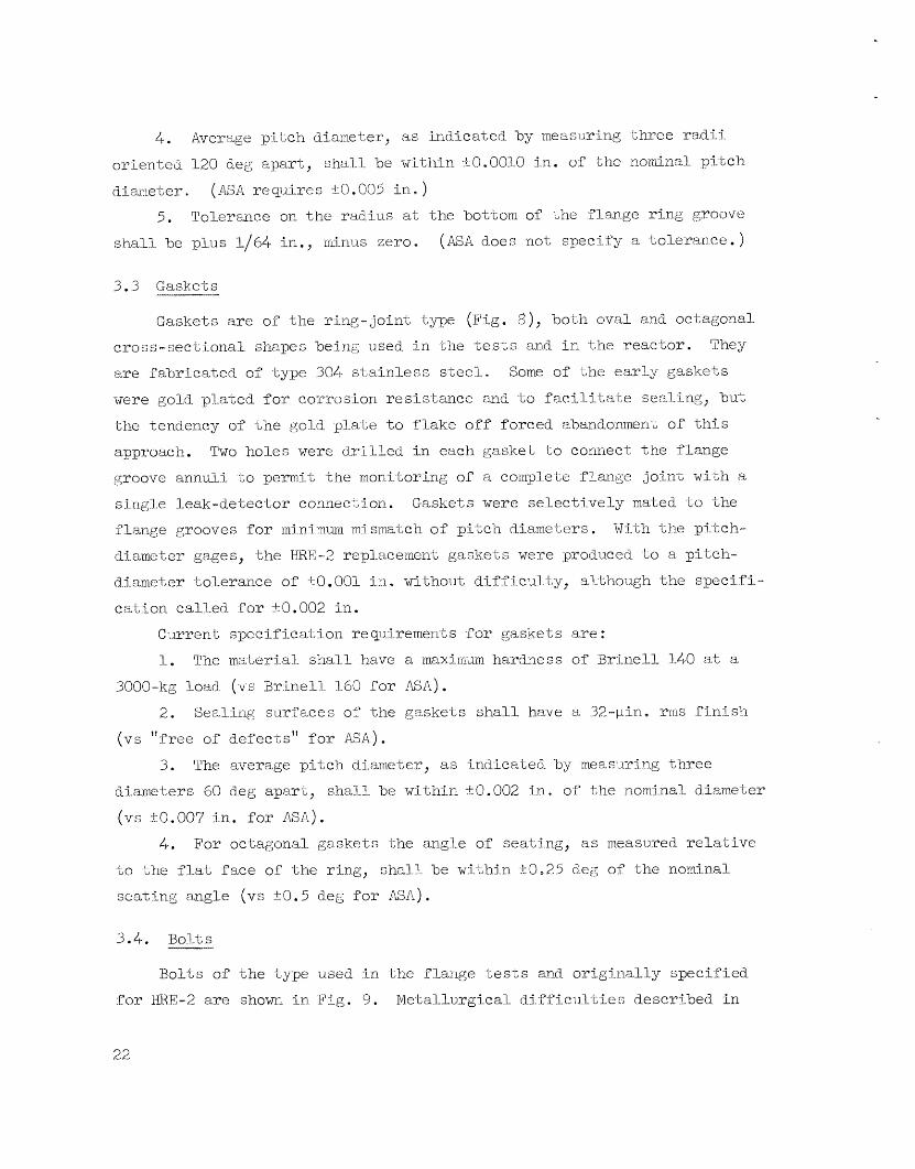
4 . Average p i t c h diameter, as indicated. by measuring 'cihree r a d - i . i
oriented 120 deg apar t , shal..l be w-ithtn ?:0,0010 i n . of -the nominal p7i:tch
diaimeter. (ASA requires k0.005 i n . )
5. Tolerance on the radius a t the bot-tom of the Slange r ing groove ( M A does not specify a to le rance . ) shall. be plus 1/64 in . , minus zero.
3.3 Gaskets
Gaskets a r c of t he r ing- join-t t n e (Fig. 8), both oval and octagonal cross-sectiional shapes being used. i n the t e s t s and i n the reac tor .
a re fabr ica ted of type 304 s t a i n l e s s steell_,
were gold plated for corrosion resis-tance and -bo faci . l i ta te seal-ing, but
the tendency of t h e gold pl_a-t;e t o f l ake o:Cf forced abandonment o f t h i s
approach. Two holes were d-r-i l led in each gasket t o connect t he f lange groove annuli t o pern i t t he rn0n.i.-toring of a complete flange jo in t w i t h a
sing1.e leak-detector connection.
flange grooves for rninirnwn mismatch of p i t ch d.iarn.eters . d-i-ameter gages, t he €BE-2 repl.acernei1-t gaskets were produced -to ad pitch-
d.iam&er tolerance of kO.001 i.n. wi-thout d t f f icul..ty, alkhough t h e spec;-fi-
ea-tion called- for rt0.002 i n .
They
Some of the e a r l y gaskets
Gaskets were select!-vely mahed ta the With -the p!.'l;ch-
Cinrrcnt; spec i f ica t ion reqii-irernents for gaskets a re :
1, The material siia11 have a inaxixizum hardness of Brinell 140 at a
3000-kg load.. (vs Brrinell- 1-50 f o r !SA) . 2. Sealing surfaces of the gaskets shal l have a 32-pin, r r n s f i n i s h
(vs "free of defects ' ' for AM).
3. The avzrage p i t c h diarrietty, as -i.ndica-l;ed. -by measi.i.j?ring three di.anieters 60 d.eg apaacBt, shall be within rt.O.002 i n . of the nominal diameter
(vs -t-O.OO? i n . f o r ASA) . 4 , For oc-Lagonal gaskets the angle of seating, a s rnea,sured relative
t o the f l a t face of the r ing, s h a l l be wi th in t-O,25 deg of the namj.nal
seat ing angle (vs st0.5 deg f o r ASA).
3.4. B o l t s -_I
B o l t s of the type used in the f lange t e s t s and orig;inal_ly speciPied
for €EX-2 are shown i n Fig. 9. Metallurgical dif.ficiil_ticc described i n
22

Sections 3.7 and 3.8 7.ed to material a id design modifi-cations, however,
am3- the final. configwaiion i s shown i n F ig . 10. The shanks of the b o l t s were t u r n e d down t o the 'chread root diameter to jncrease the elasticity of
the systems, and the e n d s were pointed to f ac i l i t a tc rcrnatc insta , l lnt ion.
Regular b o l t s with exbra high regula heads (rather: than heavy heads) were
UNGLASSI F l E Q ORN b- LR- DWG 59786
m OCTAGONAL RING
O V A L R I N G
P
Dimensions ( i n . ) Ring
P A B H c: No . R-12 1 9/16 5/16 9/16 b/2 0.206
R-18 2 3 /8 5/16 9/16 1/2 0.206
R-26 4 7/16 11/16 5/8 0.3135 R-38 6 3/16 5/8 7/8 13/16 0.413
E-39 6 3/23 7/16 11/16 5/8 0 a 305
Fig. 8 . Common HRE-2 Ring-Joint; Gaskets.
23

U N C L A S S I F I E D ORNL- L R - DWC 59787
......................
Ferrule B o l t Dimensions ( i n . ) .. ........... Flange Size Mark Ma& size I._ -I.-. ____ ---_I.-_
No* ( i n e ) A B C D E F G H No.
1 1/2 l./4 1 1./4. 1 1/2 3 1/2 0.40 1/2 1 3 N C 7 l/2 1/2 in., 300 1.b A
2 5/8 1/4 1 1/2 1 3/4 3 1-/2 5 / 8 0.51 5/8 Ll.NC7 5/8 3/4 h., 300 l b s 3 5/8 l/A 1 1/2 2 3 3/4 5/8 0.51 5/8 l ~ l . N C 7 5/8 1 in., 300 l b B
4 3/4 1/2 1 3/4 2 1/2 4 3/4 3/4 0.61 3/4 lONC'7 3/4 1/2 in., 1500 l b C
5 3/4 1/2 2 1/4 2 3 / L + 5 1./2 3/4 0.61 3/4 10NC7 3/4 1/2 j.ne, 2500 l b D
6 3/4 1/2 2 3/8 2 7/8 5 3/4 3 /4 0.61 3/4 lONC'7 3/4 3 in., 300 lb E
7 3/4 1/2 2. 1/2 3 6 3/4 0.61 3/4- 10NC7 3/4 4 in., 300 lb E
8 7/8 1/2 2 1/8 2 7/d 5 1/2 7/8 0.7l 7/8 mC'7 7/8 1 in., 1500 l b F
9 7/8 1/2 2 1/2 3 6 7/8 0.71 7/8 9NC7 7/b' 7. in., 2500 lb G
11 1 3/4 3 5/8 3 5/8 8 1 0.81 1 8NC7 1 2 in., 2500 1b J
12 1 l/8 3/4 4 3 l/& 8 1 1/8 0.90 1. l /8 8Nr/ 1 1/8 K
13 1. 1./4 1 3 3/4 4 1/4 9 1. 1./4 1.00 1 l / l~ 8N7 1 1/4 4 in., 3.500 lb L
1.4 1 1/4 1 4 1/2 5 10 1./2 1 1/4 1.00 1 1/4 8N7 1 1/4 3 in,, 2500 l b M
15 1 3/8 1 5 1/2 6 1 2 1/2 1 3/8 1.10 1 3/8 8N7 1 3/8 G in., 1500 l b N
17 1 1/2 1 5 1/4 6 12 1/4 1 1/2 1.20 1 J./2 8N'I 1 1/2 4. in., 2500 l b Q 18 1 1/2 1 5 l/t+ 7 13 1/4 1 1/2 l,20 1 1/2 8N7 1 1/2 4 in., 2500 l b SP R
- I_.__ ..... -.._ ....... _______I .-
10 1 3/4 2 3/8 2 7/8 6 1 0.81 1 8NC7 1 11/2 in,, 1500 l b H
16 1 1/2 7.. 4 7/8 5 5/8 11 1/2 1 1/2 1-20 1 1/2 8N7 1 1/2 3 1/2 i.n*, 2500 l b P
1.9 1 1/8 3/4 4 5 1/4 1.0 1 1/8 0.90 1 1/8 8N7 1 l /8 2 l/2 i.n., 2500 lb SP K .....
+0.01.0 Decimals +1/32 Fractions Tolermcc? :
Fig. 9. Original., Hm-2 Bo1t;s.
specif ied t o f a c i l i t a t e hand13 ng with ex i s t ing roemot e -maintenance tool ing
a t T3IIE-2.
The b o l t s used i n t h e STRE-2 were purchased in accordance with AS'i'M
A193-55T, gra(3.e R7, AIS1 type 4140 s t ee l , except thai; the steel., w a s 'm be
alurninum-ki.lled, wT-Lh a nzinini-urm tenstl-e s t rength of 115 000 p s i and a m i n i -
mixn y ie ld s-trength of 100 000 ps i .
specified as 20$, m d tempering at 1200°F with an o i l quench o r blowdown
with a i r was m.auldato-xy.
The - m i n i n u n elongation in 2 in. w a s
'The t a rge t hardness was Rockwel-l C-24 t o -30.
24

Special inspect ion requirements inclil-ded. the i x e of rnagneLic -particle in-
spection (Magnnflux) after preliminary machining and- heat; treatment, cheek
t e n s i l e t e s t s , and 100% dimensional inspection of thread,s, which were of
UNCLASSIFIED OR N L-LR- D W G 59788
BOLT HEAD TO BE AMERICAN STANDARD REGULAR SEMIFINISWED HEX WITH HEIGHT AS NOTED
/- 7
Dimensions ( i n . )
H B C D F R T
Bolting Dirnerisions ( i n . ) -.-- - ~ I _ -
H R C D F R T Size M:i rk Service No* ( i n . )
AA
BPJ
CG
DD
EE
FF
GG
mi
JJ
KK
1/2 in . , 300 l b
3/4 i .n., 300 lb 1 in., 300 lb
1/2 in . , 1500 lb 1/2 i n . , 2500 1b 3/4 in . , 2500 1b 3 in . , 300 1b 4 in . , 300 l b
1 in., 1500 1b 1 in. , 2500 lh 2 in., 2500 lb
3 in . , 2500 1b 3 l./2 in . , 2500 1b 4 i n . , 2500 l b
2 1/2 in. , 2500 1.b SP
4 in . , 2500 lb SP
4 in., 2500 l b P I E
4 1/2 1/2 1. 1 /2 1- 3 / L 3 1/4 0.40 1/7.6 1/2 13uC\Tc
4 5/8 5/8 2 2 4 0.31 1/16 5/8 llUNC 4 518 5/8 2 2 4 0.51 1/16 5/8 1IUl‘K!
4 3 /4 3 / 4 3 2 1/2 5 1/2 0.61 1/16 3/4 1OWJC
4 3/4 3/4 3 2 1 / 2 5 1/2 0.61 1/16 3/4 1 0 U . W 8 3/4. 3 /4 3 2 1/2 5 1/2 0.61 1/16 3/4 IOIJPTC 8 3/4 3/4 3 2 1./2 5 1/2 0.61. 1./16 3/4 1OUNC
4 7/8 ?/8 3 1/2 2 3 / 4 6 1/4 O . ’ I l 1./76 7 /8 9UNC L, 7/8 ‘?/8 3 1/2 2 3/4 6 1/4 0.71 1/16 ‘7/8 9fJNNC
8 1 1 5 3/4 2 1/2 8 1/4 0.81 1/16 1 8UNC
8 1 1/4 1 1 /4 ‘7 1/2 3 10 1/2 1.00 1./8 1. l / i k 8N
8 1 1-/2 1. 1/2 8 1/4 3 3/4 12 1.20 1/8 1 1/2 8N
8 1 1/8 1 1/8 8 2 3/4 10 3/4 0.90 1/8 1 1/8 8N
4 3/4 3 /4 3 2 1./2 5 1/2 0.61- 1/16 3/4 ~OIJPK!
8 1 1/2 1 1/2 8 1/4 3 3/4 12 1.20 1/8 1 1/2 ai
8 l. 1/2 1 1/2 10 3/4 3 1/2 14 1 /4 1.20 J-/8 1 1/2 8N
8 1. 1/2 1 1/2 6 3 1 j 2 9 1/2 1.20 1/8 1 1/2 8N
Fig. 10. Present NRE-2 Bol ts .
25

t he uiii€ied threa,d form, class 2A f i t , i n accordance w i t h ASA Siandaxd
R1.1-1-949. Ex-pcri ence i n procurement of these b o l t s subsequently l e d t o
t h e i ~ s e of an ATSL type 1+31;.0 s t e e l f o r mplacements t o assure m o ~ uniform response t o heat treatment-
t e n s i l e strengSih and ellongati on requireriicnts e
Experience a l so l ed t o relaxati-on of Lhe
3. 5. Ferrules I ~ l " l l * " - . . . -
The f e r r u l e s were made of AIS1 type 4-1-130 s t e e l t o permit the welding
of t he ferrules t o the flange, si.nce type 4130 s t e e l would have a more
favora'nl-e response -to Localized heating - k h a n tyTpe 4140 s t e e l ( t he b o l t mater ia l ) . The :i?irs.t :ferrul.es had "feet" (see Fig. ll-) t o span the b o l t
hole. I n prac-Lice, however, a corriI.gated spacer w a s placed ins ide the
:Eer-rul_e and around the shank. of the bolt f o r centex5ng. T h i s perm.'LLbed
redesign t o configuration simwn i n Fig, 1-2, which a l so helped- al-leviate
t he metallurg3.cab d i f f i c u l t i e s described i n Sect:i..oxi 3.7.
'?he physical--propcrtyJ t e s t ing , and i.nspeet,i.m. r e qii.irement s were
si..m.ilar t o thosc forq the b o l t s (see see. 3.4) . Subsequent experience i n
rnanuPa,c Lure and use of -LIE f err1xl.e s indicaked the d.esirabil_tty of a change
t o an AIS1 L y p e 4340 steel, as i n the case of the bolbs.
3.6. Nuts
Heavy, semi Cinished hexagonal nuts were purchased t o AS'IM Al94-35'1',
grade 2H, wi.Lh unified t2nwxl form, cJass 2B f i t , i n accordance wiih ASA
B1,1-1949. Speci-a1 inspections included magnetic-particle tests, Lensile
t e s t s , and di -mensicma1 chzcks e T h e requiremenis for an aJ.urninurn-killed
s tee l were relaxed A maximum hardness of Rockwell C-30 w a s specified
Mc?tal_lurgi..cal and comxsion d i f f i c u l t i R s are discussed i n Sections 3.7 and 3,8.
3.7. Mctal.l-i;lrgical. D i f f i c u l t i e s _I___
Several of the b o l t s ordered f o r HEE-2 f a i l e d i n servicc i.n flange
-ILe & Eo . 2. Subsequent observation of the bolts, nuts, and f e r r u l e s con-
currcn t ly instal_l.ed i n the reac tor disclosed that; a number of those had
severe cracks. An inves-t;-i.gation of the metallu.rgica1 h i s to ry of -%he
26

,
UNCLASSIFIED 0 R N L- L R - DW G 59 789
Ferrule Bolt Di-mensions (in. ) Bolt Mark Size M m k No. (in.) A B C D E No.
A
B C
D
E F
G
H J
K L
M
N P
Q R
1./ 2
5/8 3/4
3/4
3/4 7/ 8
7 / 8 1
1
1 1/23
I.. 1/4
1 3/8
1. 1/2
1 1/2
1- 1/2
1 1/4
0.74 0.91.
1.07
1.07
1.07
1.24
1 D 24
1.40
1.40
le%
1.75
1.75
1.93
2*11
2.11
2.11
0.63 1 1/4 1/2
0.75 1 114 5/8 0*88 1 1/2 7/8 0.88 11/2 1
1.00 1 3/4 1
0.83 1 1/2 1. I./$
1,00 3- 3/4 1 1/8
1.13 1 3/4 1 J-/8
1.13 1 3/4 1 5/8
1.25 2 1
1.38 2 1/4 1 7/8 1.38 2 1/4 2 114
1.50 2 1/2 2 ?/8
1.63 2 1/2 2 1/2
1.63 2 112 2 3/4
1.63 2 1/2 1 5 / 8
3/l6
3/16
3/16
3/16
3/16
3/16
3/16
3/16
3/16
3/16
1/4 L / 4
1/4
u 4 1/4
1/4
1
2, 3 4 5
6, 7 8
9
10
1 l
12
13
14
15
1.6
17
18 - -
Fig. 21. Original HRE-2 Ferrules,
27

UNCLASSIF IED ORNI. . -1-R-DWG 59790
..........---... .. ______ ............. Femxlc B o l t Dimensions ( i n . ) l3ol-t
Mark Mark S i z e _-...-...... -- No. (jn,> A B L No.
AR
BR
CC
DD
EE
FF
GG
m1
l/2 3/L.
3 /4 1.
5/8 1-5/16
'1/8 1 1/4
1 7_ 7/16
1 1/4. 1. 3/4
1 1/2 2 1/16
1 1/8 1 9/J-6
5/8 1/2 AA 3/11 518 RR
?/8 1 CC 1 1 118 DO
1 l/S 1 5/8 Eli:
1 3/8 2, l/d, klF
1 1/4 2 H-K
1. 5/23 2 112 GG, SJ or I(x
Fig. 1 2 Present lhW-2 Fe rmles *
various i t e m s revealed that the mechanism responsible for cracking w a s
an lirnproper quenching technique, ~~ ln ich caused cracks at regions of s t ress
concentmtion (corners). A s a, r e su l t of t h t s investi-gatioa, 5.t was
28
recommended f o r bolts, nuts, and f e r r u l e s t h a t :
1. a,lu.minum-killed (deoxidized) steel be specified t o assure a more uni- form s-truc-twe and minimize possible microfissures;
an o i l or" air-blowdown quench be specified t o mrir!irnize the soverity
of the quenching operation;
3. metallic coatings be eliminakd;
4.
2 ,
a minimum radius under the head and a rounded thread form he specif ied t o eliminate s t r e s s r a i s e r s ;
a g r w t e r than n o m 1 elonga2;:i.m be specifi-ed a t the mhimm t e n s i l e properties, implying grea te r care and selee-tjivity i n the heat treat-
ment;
Magnaflux inspection sf the bol t and nub blanks be p e r f o m ~ d after
heat treatment t o reject i t e r a s cracked in mnufactLxre.
5.
6 .
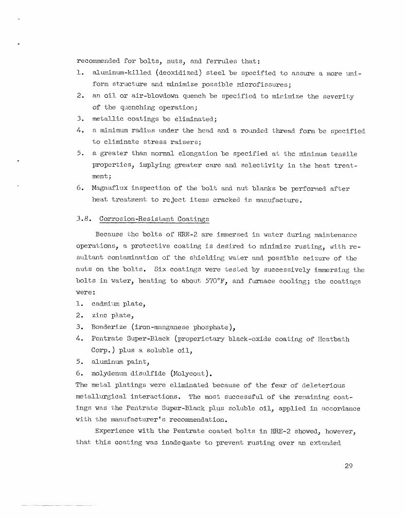
3.8. Coi?rosion-Resistant Coatings
Because the bolts of WRE-2 are Lmnzersed i n water duTing maintenance
operations, a protect ive coating i s desired to minimize rusting9 with re-
su l tan t contamination of the s ' iaield.ing water and possible s e i z u r e of the nuts on the bo l t s .
bol ts i n wateer, beating to about; 570"F, and. furmace cooling; the c o a t h g s
w e r e :
Six coatings were tes ted by successively immersing the
1. cadmium plate ,
2. z inc p la te ,
3. Bonderize (iron-manganese phosphate),
4. Pentrate Super-Black (groperietaxy black-oxide coating o f Heatbath
C O ~ . 1 plus a. soliible o i l ,
5. aluminum paint ,
6. molydenuln d isu l f ide (Molycoat ) . The metal pla t ings weye eliminated because of the fear of c3.eleterious metal lurgical in te rac t ions . The mast successful o f the rerraining coat-
ings was -[;he Pentrate Super-Black plus soluble oil, applied i n accordance w i t h the -mlu.fa@tmert 5 recommendation,
Experience with the Pentrate coated bolts i n 3EL1RE-2 showed, however, t h a t t h i s coating w a s inadeqmke t o prevent rusting ~ v e r an. ext;r;nded
29

period in t he yeactor envi.ronrnent . i s being made, specif ical- ly coatings of z i n c (melt ing point, 787°F ), nickel.
(melting poli-nt, 2651"F), and ceramic,
A further inves t iga t ion of coai,ings
3.7. Tnsula'o ion __.
Insu la t ion specified f o r Y l - 2 cons is t s of R mapping of Len laycrs
of cr inkled O.O-LS-in, aluminurn f o i l r e t h aa aggregate thickness of 3/1+ i n .
4.1, Extensometers __rY_
T h e problem of accurately monitoriix bo l t stress through thermal cycles
i s not sirnpl-e, and several. tec'miques were .tried. du~ri.ng the f lange tes-t
program.. In f lange -test No . I_, Baldwrin high-temperature s t r a i n g a g e s were
used. The rigors of the t e s t were t o o much for most of the gages, and
too few survived. t o y i e l d usefu l da ta , The leads were ca r r i ed out sTi.ng1-y
between the fl-anges, and.. the suscep t ib i l t t y of the leads t o damage, both
during disassembly and dwri.ng opera.t;ion, seems t o have heen the cause of -the fa i l .u res a
In the furnace t e s t s ( s e e see . 5 . l ) whLch were carried. out a t re la -
-ti.vely low tempemtines, it w a s possible t o use pape:c s t r a i n gages, and
an improved method was used (Fig. 13) chanical. da,mage. Here the l e a d wires
the b o l t in a cable a,nd ternzinaLed i n
the b e l t . This arrangement proved t o
to t he high-temperature gages t o makc
For f i e l d use a t the ERE-2 s i t e ,
f o r protecting the leads from me-
were carried. twough the center of
a cable connector a t the point of be sa t i s f ac to ry and could. be applied
them much more rugged.
a C-clamp extensometer was destgned
and b u i l t . T h i s device consisted of a l a rge C-clamp with a hardened anvi l ai; one end and a d i a l i i idicator at, the other. The d i f f i c u l t y of mai.ntain- ing a consis tent surface o r indentation on the ends of the bo l t s , of pro-
tecting the contacting anvill..s of the extensometer, m d of obtaining con- s i s t e n t read-i-ngs iJnder fiel..d. conditi-om reiidered. the device useless e
I n fl-mge t e s t No. 2, pin extensometiers (Fig. 1 L t - I were used-. These consisted of a s t e e l pin rin a hole along the axis of the b o l t that w a s
30
UNCLASSIFIED ORNL-LR-DWG 59791
BRIDGE WIRING DIAGRAM -\ ),
ACTIVE GAGE ,' /y 4 CONDUCTOR CABLE RUN -TIiROUGHS
ILES, FITTED WITH TERMINAL BLOCKS
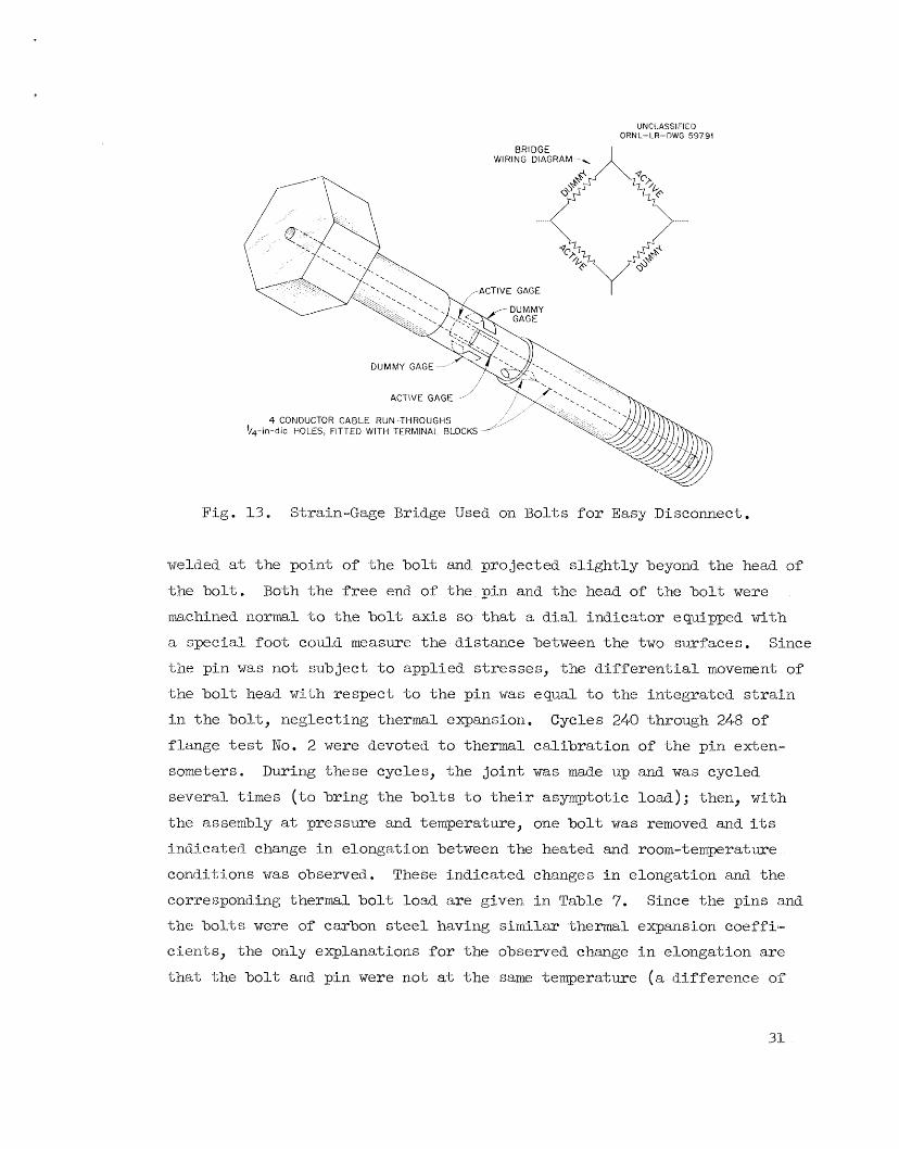
Fig. 1 3 e Strain-Gage Eridge Used on Bolts f o r Easy Disconnect.
welded at t he point of Lhe bo l t and projected s l i g h t l y beyond the head of the b o l t . Both the free end of the pin and the head of t;he b o l t were
machined normal. t o t h e b o l t axis so that a d i a l ind ica tor equtpped with
n special foot; could measure the dis tance between t h e two surfaces. Since
the p i n w a s not subject t o applied stresses, the d i f f e r e n t i a l movement of the b o l t head with respect Lo t h e pin was equal t o the in tegra ted s t r a i n
i n the bo l t , neglecting thermsL1 expansion. flange t e s t No. 2 -were devoted t o thermal ca l ib ra t ion of t h e plin exLen- S Q E ~ ~ X - S , During these cycles;, t he j o i n t w a s made up and was cycled
several. 4 ; imes (to bring the bo l t s t o Lheir asymptotic load); then, with
the assemb1.y at, pressure and temperature, one b o l t w a s removed and i t s
indicated change i n elongation between the heated and. room-temperature
conditions w a s observed. These indicated changes i n elongation and the
corresponding therm1 b o l t loLad. are given i n Table 7. Since the pins and t h e bolts were of carbon sbeel having similar thermal expansion coeffi-
cientss, the only explanations f o r the observed change i n elongation are
t h a t the b o l t arid pin were not a t t h e same temperature (a difference oz"
Cycles 240 through 248 of
31
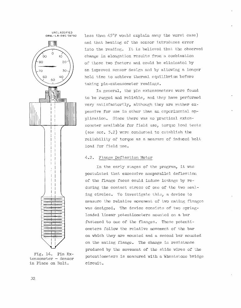
UNCL ASS1 F l E D O R N L - L R - D W G 59792
Fig. 14* Pin EX- Lensometer - Sensor i n Place on Bolt .
l e s s than 45°F woul_d explain away the worst case)
and tha t heating of the sensor introduces erT"oY"
i n t o the readinp;. :Lt i s helicved t h a t the ohseme-td
change i n elongation r e s u l t s froin a cornbination
of these two f ac to r s arid could be elirniriated by
an impmved sensor design. and by allowing a 1one;er
hold Lime t o achieve thermal e q~ni l ibr i_ iun bef or2 taki-ng pin-extensometer readings.
I n Seneral, the p i n extensometers were found
t o be 3"ugged and r e l i ab le , add ihey have performed
very sat i-sf ac t o r i l y , although they are rather ex- pensive for use i n oi,l.icr than an experimental ap-
plication.
somete% avaj lable f o r f i e ld use, tor?que load t e s t s
( s e e sec. 5.2) we-m conducted t o esta'nlj-sh the
re1ia'biliLg.r of torque a s a measwe of induced b o l t
load for f'ield u s e ,
Since there w a s no prae t ical- e x t e n -
4.2* Fl-ange Deflection Meter
In the ea r ly stages o:f t he program, it was postula%ed that excesstve nonparallel def lec t ion
of the flange faces could induce leakage lay r e -
ducing the contact S'LXYSS of 0~1.e of t& two seal..-
ing c i r c l e s . To Lnvestigate this, a device t o
measure -tihe rela-Live movement of two rmL:ing fl-angc s
was designed. The device consists of t w o spring-
Loaded I-inear potentiomekers mounted on a bar
fastened. t o one of the flanges-;. Them potent i -
ometers :follow the rel.at:kve movement of the bar
on which they are mounted and a second bar mounted.
on the mating flange. The change i n resistance
produced by the movement of t h s s l ide wires of Lhe potent:immeters i s nieasu.red with a Wheatstone bridge
c i r c u i t .
32

T a b l e '9. Apparent %iermlal C a l i b r a t i o n f o r P i n Fxtensometers
F lange Size and Nurn'uer __I_- _____.- --.-.--
3 1-/2 j.11. , 2500 l b
2 in . , 2500 Yo
'' No, 2 110- 3 No. L No. 4- JVo. 5 No. 8 -
Fe rml e No YCS NO Yes No NO Yes
Apparent r e d u c t i o n i n b o l t 0.9 2.1 1. '7 2.15 2.35 2.4 2.1.4 e l o n g a t ion i n cooling from 637 t o 70'3' a t zero b o l t load, mils
parent change i n elonga- tion, l b
Bolt load eyuiva-lent to ap- 8 e00 37 400 17 000 36 800 49 500 81. 700 59 200
D a t a from one o f the devices i n s t a l l e d on a, 3 L/2-ineJ 25OO-lb flange
jo in t w a s compared with data, from two 0.001-in. d i a l indicators during the
bolting-up operation and were found t o be a t least; as a,ceiirat;e as the ind i -
ca tors used. The device can apparently measure flange defl.ec-t,ions t o
-9-0.0002 i n . and flange ro ta t ions t o k0.5 min. The i n s t a l l a t i o n on the 3 1/2-in., 2500-lb flanged j o in t indicated
t h a t a b o l t Load of 145 000 lb (18 000 L b per bo1.t) induced a ro t a t ion of
Lc, mi.n and a def lec t ion (at the edge of the f lange) of a,b01.2t 0.025 i n .
Since the flanges used i n flange t e s t No. 2 did not Leak excessively, t h i s
l i n e of invest igat ion w a s not pursued.. any fur ther .
4.3. Leak Detectors
The discussion of leak det;eci;ors presented here is r e s t r i c t e d t o the
type of detect ion axid measurement used i n the flange development program
and t o the reduction o f data recorded with t h i s type of d.eLect;ion. The
leak-detection technique adopt;ed f o r the experiwne-n-tal program consisted.
of observing t h e r a t e of presswe rise i n the ring groove annul-us a f t e r
evaci.;latiwig and sealing off the amulus. The system i s shown schematically
i n Fig. 15; it cons is t s of tubing connecting the annulus Z;o a thermocouple- type vacuum-gage tube and t o a vacuufl valve, Two holes are d-riU-ed through
the. r i ng gasket t o connect the two annuli and t o permit rnonitorsin.g of the
33

U M C I.. AS S I F I E D 0 R N L - L R - DWG 5 9 7 93
C O N S T A N T - V O L T A G E POWER SOURCE
I- E A K - DE 1- E C T O R A N N U L U S I
THEHM0COUPL.E - T Y P E VACUUM-GAGE TUBE
/ VACUUM V A L V E , CON' I~ROLLED FROM I N S T R U M E N T P A N E L
TO VACUUM HEADER
Schrmatic Di agram of T,esk-Deteetor Sysi,e-tm.
ent;:ire j o in t wtLh a sing1.e leak detector . This -i;ecl.uiiqi.ie i s incapable of d.eterminiiig whe-tfkx- the indicabetl. leakage lies :l%xn. the process side t o the
amulus o r from the atmosphere tc:, t h e ann.ul..us, bu-t since sa- t isfactory op-
era-tion of the reac tor 1.eak-detector sys-tem requires a tri.ght seal on both
seat?-ng sinface s , the exact; leakage pa-bh i s of secondary tnterest, e
In all the work reported, fl.atnges were rmintained in. the vapor phase
of the loop, and. leak rates are reported ?.n. graarns of' m,t,ey per day. The
t hemnoc oinpb e --hype vac imm- gage t ubc s used were e a1 ibra- t e d. u.nder both stat :i c
and -t:ran.sient condittans by meteying a i r slowly i n t o a known evacuated
vol.i;lrne. The response of t h e tubes was Pound t o be sufficicnLly imifo-m and. cons is ten t i;lncl.er tmns ien t s and am.ong c-3.Sferen-t tubes to p e m i t a

s ingle ca l ibra t ion c i ~ x v e t o be used for a l l tubes, provided t h a t the proper
voltage (determined i n the calibration) w a s applied to tho heating element;.
In t;he f i n a l leak-detectmr installation f o r flange test; Mo, 2, the
vacuum valves were ecpipjped w i t h air-operated cont ro l le rs arid were arranged
so tihat they could be operated from %he c o n t r ~ l panel. tubes were conxiected t o a recorder through a gang switch so t h a t individual
rates of pressure rise could be recorded.
vttcuurn-gage tubes were switxhed t o a panel. meter, and time between Lwo pressixes w a s read with a stop wai;eh.
The vacuum-gage
For very high leak rahes , the
The leak rate was cal-culatcd by using the perfect-gas law, asszarning
an appropriate average ternpera-biwe f o r the evacuated volume . The follow-
ing voLimes were calculated f o r the leak-d-etection systems of the flange
tes ted :
Le rtk -De t e c t ion
L/2-in. 1500-Ib flange l - i n * , 2500-lb flange 2-in,, 2500-1.h flange 3 1/2-ine, 2500-1.11 PlctYlge
49 51 60 90
4.4. Pitch-Diameter Gages
Duriiig the procurement of components f o r HlXE-2 mid during the enrly
s-t,agcs of the flange development program, i% w a s observed that; the tech-
ni.qii-es availab1.e f o r the dimensional inspec tion of r ing- jo in t gaskets and
flange grooves w e r e inadequate . ‘ T h i s inadequacy stemmed f m m ERE-:! re-
quire~nents f o r a doubl..e seal, since the double seal necessi ta ted c loser
tol.erances than were normally used, although, in general, tools were not
avatJ-&le t o demonstrate s t r ic t confoxmance even t o MA 1;oLerances . Inquiry sh.owed t h a t commerciall_y used inspeetion t ecb iques i.ncluded
(1) gasket p i tch diameter measurement with a modified vernier caliper, a slaw, ted.ious operat,ion with .inadequate sens i t i v i ty , o r Pitting of the gasket; t o a, brass master groove by touch; (2) flange-groove pitch diameter
mea.siaement by a pLi@ gage or comparison w i t h a mabe msLem. template by
35

ixse of backlight<-ng, techniques which lack sens i t iv i t,y; and (3) measixre-
mm'L of the bevel angles c)Lo octagonal. gaskets o r o f the r i n g groove wi.th
a machinist 's proiractor , a sat:-sfactor-y- technique. It fu r the r sezmed
that, since complaints from ixsers were rare and the avai lable ecpi ptnent
w a s inconvenient to use, physical inspection of gaskets and grooves was
usually of a cursory nature . Xt w a s believed tha-L i-m-proved inspection eqii.iprizent w a s necessary,
not only f o r experimental measuremenLs OF test fll..anges, hut for inspec--
tion of €IRE-2 cornpsnent s . from several gage rmnufactixers, with t he r e s u l t t h a t a contract w a s entered
i n t o with Federal Produc-1;s Corporation of Providence, Khode Island.. Federal
designed and. b u i l t a set of pi-tch-diarnet,er gages (Fig. 1 6 ) which have proved.
t o he accurate and easy t o iise. 'The s e t cons is t s of f'oim gages and covers
p i t ch diameters from R11 (1.. 11/32 i n . ) t o Is67 (3-8 1 /2 i n . ) i n the follow-
ing ranges :
@r*:iteeria were prepared. and- proposals WXY sought
Gage No. Range I
1 Rl.1 -Ti20 2 K2l-R37 3 Ti38 -E&-/ 4 R ri-8 -E 6 7
An a;i;-Lar,hm.ent has been made t o a l l o w gage 3 t o m.easuTe an. R.54 d.iametere These gages a re of the cornparstor -type and are used by first a t tach-
Ting the contactling anv i l s approprLatc t o -Lhe surface t o be gaged (ma1.e o r female an.r!. .to match width of gasket o r groove) and then placing t h e ga&
on a -rrias.t;er pl.a,te and se t t i ng the dial.. i izdicator t o zeyo. The gage 3"s
'c;heri placed on 'che pa r t t o be measured., and the devia-ti.on of the d t a l i nd i -
ca to r from zero -is 1.250 times the ac-tua.1 deviation of t he rn,eaas.i.~ed pitch.
diameter from the rmster e The devices ind ica te va r i a t ions of -pi" ' ~ c h di, - aineter as t h e t r a n s l a t i o n of one contact point wi-th respec-i; t o -i;wci fixed.
con-tact points A calcid-ated ca l ib ra t ion indicaked t h a t the gages can
accix-akely measure pi-kch dri_a-me-ters t o fO. 0009. i n ,
rnaster r ings have been fabricated i n tile sizes E l l - -i;lxsugh 7240, K50, R5J+, and B66.
Master x5mg grooves and
36
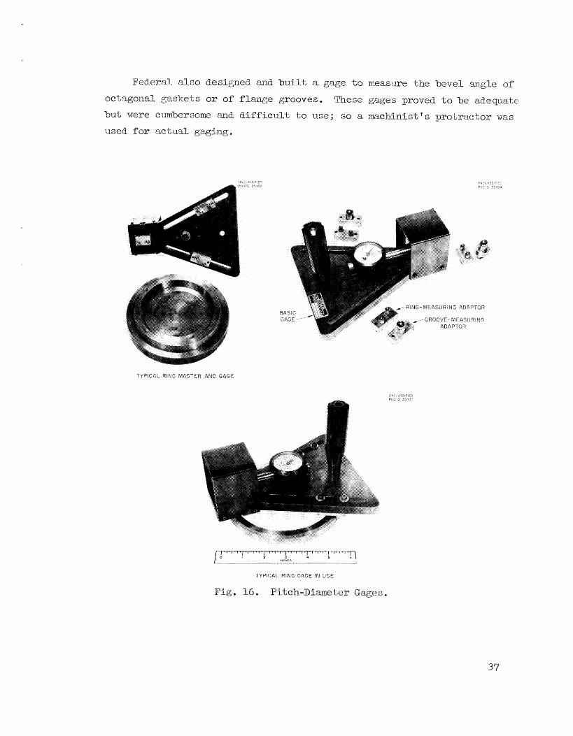
Federal also designed and b u i l t a gage to measme the bevel angle of"
octagonal gasltets or OS flxxge grooves. These gages proved to be adequate
but were cumbersome and difficul.t to use; so a machinist's protractor was
1nsed for Izc-tual gaging.
TYPICAL RING MASTER AND GAGE
TYPICAI.. RING GAGE IN USE
Fig. 16. Pitch-Diameter G a g e s
37

5. Auxiliary T e s t s
5.1. Furnace Tests
Concurrently w i t h t h e operatton of flange
ducted. t o determine the effect, of b o l t shank diameter (a method of con-
t r o l l i n g resil- ience ) on tl:temal. loads i n flanged JoLnt s.
conduc-ted i n a f u n a c e a t r e l a t i v e l y I..ow temperati.res; so the e f f e c t s of
internal.. pressure and -temperature grad-ients were not presen'~ .
These t e s t s were
The t e s t s were eond.uc-Led on a p a i r of 3 1/2-in., 2500-lb sk i -n less
steel flanges w i t h 5tn oval s t a i n l e s s s-txel ga,sket and- grade R7 studs. I n the t e s t s -the jo in t w a s made up several times by using b o l t s with shanks
of d i f f e ren t nominal diameters.
s t r a i n gages, and the joli.ri-i;s were cycled from room temperature .to 178°F. The joint was cycled i.n a furmace at a r a t e tha t was su f f i c i en t ly slow
t o keep the f langes v i r t u a l l y isatherma.l...
temperature ~n~as recortled.
Table 8.
The b o l t s were rinstrumen-Led with SR-4
The change of bolt, load with
The da-ta :!?ram the four runs a re summ.a-rized i n
Table 8. Resu l t s of Bolt Load Relaxa t ion 'i!ests
._ _..
Run No.
1 2 3 4 ____ ...._-_.....-..____I
1. B o l t shank diameter , in . 1.332 I.* 5 I... 332 1.. 000
2. Total bol-t a r e a ( 8 b o l t s ) , 1..1.. 1. 14.1.5 11.1- 5.28 i n . *
3. Ini.t,j.al load, 1.b 93 800 151 500 1.26 500 J.44 500
A. T h e o r e t i c a l thermal load, 45 500 50 4.00 45 500 33 300
5. Actua l Liiermal- load\, lb 1 2 000 35 000 22 ILm 7 650
l b
6. F i n a l load, lb 62 500 1-04 100 101 900 123 000
7. Load. losi; duri-ng tes t 31 300 47 000 24 600 21 500 (itern 3 minus item G) , lb
8. ( I t e m 3 minus i t e m 6) as 29.6 25.2 16.6 14" 1. % of ( i t e m 3 pl.us i tem It. 1
% of (item 3 plus <.tern 5)
9. ( Item 3 minus i t em G ) as 22.5 23.3 14.3 1.2.1
38

The load. l o s t diaring each rm, as a percentage of the maximum ( i n i t i a l
plus theimal.) load, decreases with successive runs, which may be a t t r i -
bu-bed t o the f l a t t en ing of t he surface o:f the oval gasket and. i t s subse- quent abi1il;y- t o car ry grea te r loads without p l a s t i c deformation . the ac tua l thermal l o a d s do riot compare very c lose ly with the theo re t i ca l
thermal loads, they do indicate the effect iveness of increased. r e s i l t ency
i n reducing the magnitude of thermal loads. The f a i l u r e or“ ac tua l loads
t o equal t heo re t i ca l loads i s a t t r i bu ted t o the e l a s t i c - p l a s t i c act ion of
the ovaL gasket and the resu l tan t var iable contact; area.
RLthoi;r.gh
Although the experiment w a s not car r ied far enough t o e s t ab l i sh the
opi;imm area of b o l t shank, it d id ind ica te t h a t the optimum shC.zirik area
w a s smal-l_er than t h a t noniinally used with the flange. It w a s decided t o
use bol ts with shanks turned down t o diameters approximately equal Lo the
root tlwcad diameter of the b o l t and t o increase the r e s i l i ency of the
bol t ing fu r the r by the addi t ion of a f e r r u l e (a cy l ind r i ca l metal c o l l a of esxentZalLy Lhe same area as the bo1.t shank) between the bo l t and the
flange, which would increase the e f f ec t ive length. of the b o l t and. there-
fore i t s res i l iency .
5.2. Torque-Load Tests
Since Lightening with a torque wrench i s the simplest method of con-
t r o l l i n g the tensioning of ’bolts i n the f i e l d , attempts t o e s t ab l i sh re- l i a b l e torque -load re la t ionships were mad-e through a l l the experimental
work.
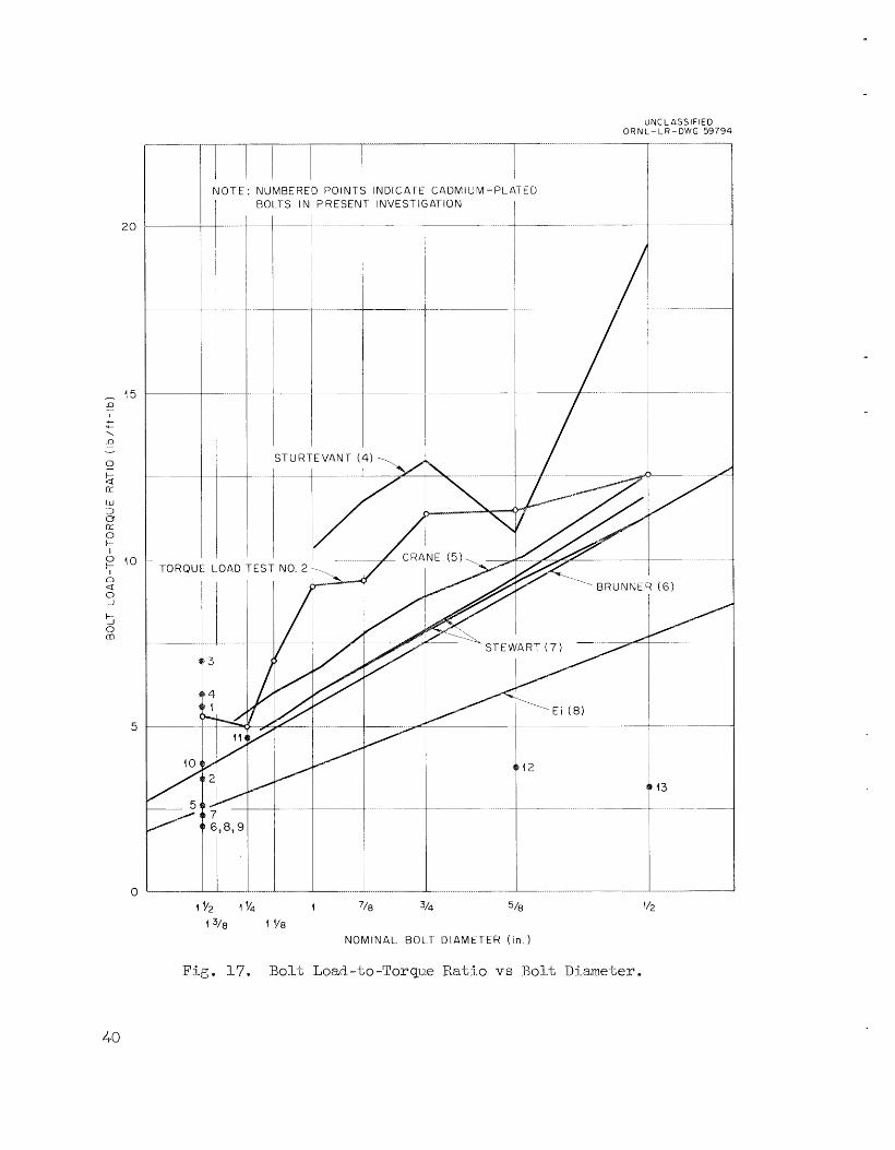
of pounds of bo l t Load per foot;-pound of borque for various nominal b o l t
diameters . Data from a l i t e r a t u r e ~ u r v e y ~ - ~ are presented i n Fig, 17 as a p lo t
I n general, these da ta ind ica te t h a t a l i n e a r re la t ionship
4P. A. St-mtevant Company, Torque Manual, pp. 2325 (1951).
’Crane Company, How t o Assemble and Maintain Flanged Joints, Piping
‘Alex Brunner , S t ee l Bolts .. . . Determining Pemissible ExLernal
‘W. C . Stewarb, Determining Bolt Tension from Torque Appl-ied t o the
“Raymond E i , Nomogram f o r Determining Tightening Torque on Bolts,
Data Sheet No. 6, Valve World, No. 1, p. 16 (1952).
Axial Loads, Machine Design, pp. 3-24-7 (June 1750).
Nut, Machine Design, pp. 209-11 (November 1955).
Design News, pp. 39-40 (January 15, 1955).
39
UNCLASSIFIED 0 R N L - L R - DWG 59794
_____. . . . __._ ... . . . . . .
I , N O T E : NUMBERED POINTS INDICATE CADMIUM-PLATED I DOl-TS IN PRESENT INVESTIGAPION
STURTEVANP (4
TORQUE LOAD TEST NO. 2 \
4 v2 4 v6l 1 718 314 518
1 3/8 1 ' /8
NOMINAL DOL-f DIAMETER ( in . 1
'12
Fig. 17. B o l t Load-to-Torque R a t i o vs Bol t Dia.me.'l;er.
4-0

may be expected between the torque-load ratio and the reciprocal o f the
nominal b o l t diameter.
w i t h the published data, but experimental data on the cadrr6.wm-plated b o l t s
o r ig ina l ly specif ied f o r HRE-2 (isola-bed &at% points i n Fig. 17) eLxhibTted
too high 8 torque-to-load ratio f o r large b o l t s and too low a r a t i o f o r
s m a l l bol ts . p la t ing on the clearance allowcd by the thread tolerances, which i s more
ser ious i n the smaller s izes f o r a c lass 7 fib. I n the eqerLmental work
ga l l i ng and crumbling of t he cadmium w a s observed, which would support,
t h i s conclusion, I n the Larger s i zes the p la t ing would c8use no i n t e r -
ference w i t h a c l a s s 7 f i t , and the smoother mating surfaces w o ~ l d permit the high loads observed. The subs t i tu t ion of the new c l a s s 2 A f i t f o r the
obsolescent c l a s s 7 f i t r e l i eves Lhis condition, :For the cleax%anee i n
class 2 A does not increase as rapidly with b o l t diameter as it does i n
e l a s s 7.
Experimental data on wLpla,ted bol-ts compared well
This deviation i s a;ttsibui;ed to t he infringemeat of t h e
Although the torque-to-load r a t i o s f o r plated b o l t s did not compare
c lose ly with t h e avai lable data f o r mpla ted bo l t s , it w a s observed that
data f o r b o l t s of the same s i ze avid from the same shipment grouped closely.
A general conclusion drawn from the -Lests i s the b o l t s of a given lot will
exhib i t similar torque-load relat ionships , but small var ia t ions between
l o t s prevent, any consis tent cor re la t ion from being drawn. It i s therefore
necessary t o conduct t e s t s on each l o t of b o l t s when close control of b o l t load i s desired by using torque.
I n making up the flange j o i n t s i n flange t e s t N o . 2 (see see. 2.4),
incremental torque and elongation data were recorded f o r a L l the b o l t s . Subsequent ana lys i s of these data indicated t h a t torque w a s adequate t o
control bolt s t r e s s t o +LO$.
w a s consis tent (i-e,, i f the b o l t s and nuts were cleaned and adequately
lubr ica ted) .
T h i s w a s t r u e i f t he condition of the b o l t s
It w a s noted during this period t h a t the torque required t o produce
a given b o l t s t r e s s decreased as the nunber of tightening-loosening cycles
increased. T h i s phenomenon i s a t t r i bu ted t o a "conditioning" of the mating
surfaces of the b o l t and nut, resu l t ing from the smoothing of minute ir- regu la r i t i e s .
41

When t h e f i n a l IBE-2 bo3.:1;s (wil;h Penbrate Super-Black f i n i s h ) were
receri-ved, it was decided t o tscondiL3vcm" -them i n the hope that t h i s would make b e t t e r f i e l d c o n t ~ o l of bo l t loads possible e Each bolt-n1lt assembly
w a s tightened. w i t h a torqiie wench i n a load c e l l a number of times uitil.
a constant load3.n.g w a s induced. several successive times by -the sadme torque
A t 'Lhis point t h e bo1.t was ca l ibra ted f a r t h e specified. -'r;orque to be ap-
p l i ed Upoil ins-tal-lati.an i n the 1-BE-2 flanges.
ing f o r t h e error introduced i n f i e l d bol t ing operations, torque wrenches can be used t o trighter! the conditioned nuts and boL-ts t o I.oads Trsi-thin 51-58 of -LIE values specif ied.
a stress of 4-5 000 ps i ( the h.-i.ghes-t; stress consid.ered reasona701e) i n the shank of t he condit:i-oned I W - 2 bolts are shown 5.n Table 7 .
I..oad-ts-torq-ue ratios a,re plo-L-Led. i n F3-g. 17 as a function of b o l t d i -
It; i s believed t h a t , allow-
Torques detemiined. dwing these t e s t s t o induce
The t8bulated
Ta.ble 9. 'Porcpe to Induce 45 000 psi i n IiEE-2 Bolts
Bol..t Ratio of Load Torque To Torque (lb/ft -1-b) ( f t - l b )
1..1 .... _..-.11.
1/2 <-ne, 1 3 U N C 45 126 5/8 in. , I.I-UNC 80 115 3/4 rime, l 0UlvC 115 ll.4 r ~ / 8 i n , , 9mc1 190 93,8 I- in., 8UNC 250 92" 8 1 l/8 in, , 8N 4-00 71.6 .I. 144- in. , 8~ 700 50.5 1 1/2 i.n+ , $N 960 53.0
-...........I.
5 . 3 . Chemical Technolngy Bivisi-om IIigh-Pre ..-..- ..... sswe Flangz Tes ts -- --..e-
During t h e period covered by the flange development program i n the Reactor Experhen-tal Xngineeri-ng Divis5.cm (FWLD ) ca r r i ed out by -the Unri-i; Operatlions See-tion of the Chemical Technology
Division ( C X B ) . diqdication w a s avorided by 3-inliting the CT> work .Lo the small flanges
a slimllar e f fo r t vas
Al..though the two efforts were conducted independen.t;ly,
42

with which they were concerned and the REED work described i n t h i s report
t o the l a rge r flanges.
but the scope of Lhe work and the conclusions reached are presented f o r
comparison with the F3EXl work.
Details of the C 'X . work w i l l not be presented here,
The CTD work was perfomled on 1/2-in., 2500-lb weld-neck r ing jo in t
flanges, t he flange used most commonly in the KRE-2 chemical processing
p l an t* General areas investigated. were (1) dimensional tolerances of ring gasket and flange groove, (2 ) surface-f inish requirenients for gasket-
groove interface, ( 3 ) increase OS bo l t r e s i l i ency by the use CJP f e r r d e s
and by th.e use of Be l l ev i l l e washers, and ( 4 ) a comparison of oval and
octagonal gaskets i n the l i g h t of other considerations,
dimensional tolerances and surface f i n i s h the CTD work confi-smE?d the work reported by the REED group.
With respect t o
The CTD work establ ished t h e necessi ty f o r introducing r e s i l i ency
in-bo the jo in t , and f e r r u l e s were used successfully t o accomplish this.
Since f e r r u l e s can make a flanged jo in t somewhat cixnbersorne, some e f f o r t
was devoted -bo the use of Bel levi lbe washers as a compact means of i n t ro -
ducing addi t ional res i l iency . The perfomnance of the washers did not
come up t o expectations, but it was concluded tha t , with fu r the r develop-
ment;, a sa t i s f ac to ry washer system could be designed. The cos t of such
a system would have t o be balanced against t h e expected savings i n space.
(Note: Although t h e Be l l ev i l l e washers mty be econornically f eas ib l e f o r
small flanges, space requirements render them impractical for l a rge r
flanges; so no e f f o r t w a s devobed t o t h e i r use i n the REED program.)
I n general, flanges made up with octagonal r i ng gaskets were more
l i k e l y t o be leakt ight and were less l i k e l y t o experience deformation of
the r ing groove than were -those made up with oval r ing gaskets.
t h i s experience, it w a s the conclusion of the CTD group t h a t octagonal
r ing gaskets should be specif ied f o r reacGor chemical plant service.
Based on
Acknowledgement; s
The work herein reported w a s a jo in t effort; of t h e Component Develop-
merit Section and t h e Design Section of the Reactor Experimental Engineering

Division (now the Reactor Divis ion) .
vision of 1. Spiewak, 17. R . Gall, and- M. 4. Lundin and the direc- t super-
v i s ion o f I. K. Narrba, P. N. Harley, W. R. Chapan, R. D. Chevertcm, J. s. Culver, H. C, R o l l e ~ ~ and J. N . Robinson,
The work was imdcr the general super-
W Q Y ~ performed by the Unit Opera,t:ions Section of the Chemical. Technology
Division w a s under the supervision of C . C, Haws.

Bibliography
1. J. 0. Axmen, Tightening Is V i % d Factor in B o l t Endurance, Machine
2 . A. E. Anderson, Improving B o l t Performance, Product Rngineerj-ng,
3. M A Code for Pressure Pipi-ng, €331.1 (1955); ASME Code f o r Un-
Design, pp. 158-62 (February 19&),
May 1949.
fired. Pressure Vessels (1956).
4* W. C. Bae-, U. S. Navy Mvist-,ry Comi.t-tee on Bigh Pressure, High Temperatme Pipe Flanges, Report to Committee by Design Subc:omitteee (June 22, 1951).
E. W. Bailey, Thermal Stresses in Pipe <Joints for High Pressures and- Tempera-Lwes, Engineering, pp. 4-4%7 (Apyil 20, 1934) and pp. 506-7 (May 4, 1934).
Petroleim Refiner, Val,, 29, pp e 1-29-33 (1-950).
finer, pp. 129-35 (January 1753).
5.
6. R. G. Slick, Bending Moments and Leakage at Flanged. Joints,
7. R. G. ELick, WOW Flanges Work and Why They Le&, Petil.olcum Re-
8. R. G . Blick, Interaction of Pressure and BerxdJ'.ng at Pipe Flanges,
9. I. €I. Carlson and W. S , Bl-ack, Joints f a r High Pressure High Tem-
AE;mE Paper No. 51-PET-9 (1.952).
pe-rati.me Piping, T r a n s . A.SME9 pp. 23'1-43 ( A p r i l 1353..).
Progress Reports, Unit Operations Section 10. Oak Ridge National Laboratory Chemical Technology Division Monthly
OR$& CF 55-12-154, December 1955
ORNL CF 56-2-154, February 1956 ORNL CF 56-3-177, March 1956
OTcTJ?.i CF 56-1-175, JCX~.LI.ZL~~ 1956
ORI!iT CF 56-4-21.0, April- 1956 ORNL CF 56-5-1.97, M a y 1956 ORNL CF 56-6-177, J u e 1956 ORrJz CF 56-7-1-50, July 1956 ORNL CF 56-8-215, August 1.956 ORE& CF 56-9-127, Se_~?t;em%er 1956 0ENp.t CF 56-10-83, October 1956 QnrJz CF 56-11-143, November L956 ORNZ CF 56-12-128, December 1956
Chemical. Teehuiology Division Monthly Progress Reports
ORTJp1-2251, January 1957
ORNL-2324, A p r i l 1957. ORNL-2270, FebruZtry 1957
11. R. B. Clements, Analyzing Effect of Bending Loads on Bolted Fkmge Joint s, Machine Design9 November 15, 1956.
45

12. C . P. Coyqhlxa, Nut and B o l t Loa,d--i.ng Cmves, OIUVL-578, February 15,
13. Crane Company, Catalog No. 53, pp. 5 2 1 ~ 2 6 .
14. J. S. Davey, Prel-oading Design Key t o Bolted Jo in t S-Lrength, D e -
1.5 . 'I' . J. Dolan, Load- Relations i n Bol-l;ed Jo in ts , Mechanical Engineer-
16. V . L. Doughtie and W . L. Carter, Bolted Assemblies, Machine De-
17. J. N. GoodLer and Ti. J. Sweeney, Loosening by Vibration of
18. 11. J. Gouch, Pipe Flanges Research -- F i r s t Report; o:P the .Pipe
3-950 .
sign. News (March 15, 1956)
i r g J pp. 6OT/-l_l (AUguS-L 1942).
si-gn (February 1950) . TWead.ed Fastenings, Mechanical Engineering (December 194-5) . Flanges Research Com.it.tce, Engineering, pp. 237-8 (Februaxy 28, 1936) a n d pp. 271-2 (March 69 1936).
1-9 . J. P. Harmnond, Prelirninaxy Results and. Reconmenda-t:ians Relative to Investigation of RET Flange Bolts, OENL CF-56-11-39, November 8, 1956.
20. C . C . Haws 'LO W . K . E i s t e r , Current S ta tus and Future Program. f o r High Yressixe Flange Testing (September 1-7, 19%) .
21. C . C . Haws, Tentative Recornendations f o r High Presswe Flange Assembl-ies, ORNL CF-56-7-13, Ju ly 3, 1956.
22. c', C. Haws, Comparison of Several.. PLne Connec to~s for I-Iigh Pressme and/or IHgh Temperature Disconnects, OKNL CF-57-10-30, October 3, 1957.
23. Heating, Pi.pi.ng and Air Conditioning, Parani&er, Current Types of Gaskets and CI1_osures, pp. 566-8 (September 1937).
24. G. Horvay, Analysis of Flanged Shell J o i n t s Bo l t Fai lure , KAPL-M-GIT-15, November 8 , 19%.
25. A. M. Ksuser, Suggested THmensions %or Pipe Fittings f o r /lt000 lb., 900"F, Heating, Piping and Air 443-4 (July 1939) .
26. W . F. Jaep, A Design Proccdwe f o r Integral. Bubs, T r a n s . ASMI, pp. 563-74 (July 1951).
27. A. E. Kom, Torque-Stress-Load Relationship Product Engineering (November 1943) .
and. the Mechanism of
Flanges md Flanged Conditioning, pp.
Flanges with Tapered
i n Bolts mil Screws,
28. A.R.C. Mark1 and H. 11. George, Fatigue Tests on Flanged Assemblies,
29. J. B. Mattimare, lkmerican Standard Steel Pipe Flanges - Their
30. J. D. Ma-ttimore, N. 0. Smith-Peterson, and H e C . Bell, Design of
KME Paper No. 49-S-6.
Development and Proper Use, ASPIE Paper No. 4-9-FTT-20.
Flanged Join-ts for Valve Bonnets, Trans. ASME, pp. 297-303 (May 1938).
31. M. P. Milliken, How Tight i s Too Tight?, Fasteners, Vol, 6,
32. I,, 5. Murphy, How -Lo U s e Chart Solutions i n Flange Designs,
33. A. McCutchen, Gaske-Led J o i n t s f o r ISigh Pressure Righ Temperature
34. E. C. Pet r ie , Flanged Piping J o i n t s - Methods T o r Applying and
No, 1,
Petroleum Refiner, pp. 131-4 (Au.g.us1; 1954) .
Piping Service, Heating, Piping and Air Conditioning, pp. r~23-7 (July 194-1).
Determining Bolt Stresses , Heating, Piping and Air Conditioning, pp. 303-7 (Jiine 1936 ) . Heating, Piping and Air Conditioning, pp. 213-20 ( A p r i l 1937) .
semblies, Product Engineering (January 1949).
(March 26, 1957).
35. E. C . Petri-e, The Ring Jo in t - I t s Relat ive Merit and Application,
36. W. F. Pickel, Tightening Charac te r i s t ics o f Nut and Stud As-
37. Pixchase Requis i t ion No. 16D-74466, Bolts, Nuts and Ferrules
38. I. Roberts, Gaskets and Bolted Jo in ts , &!ME Paper No. 47-A-2.
39. J. N. Robinson and I. K. Namba, Thermal S t resses i n KFZT Flanged
40. J. Z. Ryan and G. Melikian, Righ Pressure Flange Studies:
41. J. A. Sauer, D m C . Lemon a n d E K. Lynn, Bolts - How t o Prevent
42 , C , L. Segaser, Zircaloy-to-Stain.less Steel Transi t ion Pipe Joint;
43. J. W. S k i l l e m t o C , B. Graham, Flange Studies (October 25,
44. Society of Automotive Engineers, Inc., Torqueing of Nuts i n Air-
45. A. G. SoZokien, Why Threaded P a r t s Fa i l , Product Engineering,
46. Specif icat ion HR€'-20la, Oval arid Octagonal Ring Joint Gaskets
47.
4.8. D , Km Taylor nnd J. a. Maloney, Causes of Leakage i n IIRE Flanges,
49.
J o i n t s (March 26, 1956).
Cha,raeteristics of Be l l ev i l l e Springs, KT-274, May 30, 1757.
Their Loosening, Machine Design, pp, 1 3 3 7 (August L950).
Design Study, BFiNL CF-55-12-72, November 10, 1955.
1954) . c r a f t Engines -P~rogrcss Report N o . 1 (December 1943) .
VOX. 4, pp. 261-2 (1933) .
(December 10, 1956) e
S t e e l Flanges (Januayy 18, 1-957).
ORNL CF-53-5-225, May 1, 1953.
and Steam Piping Service, Heating, Piping and Air Conditioning, pp. 4 2 5 7 (July 1940), pp. 489-92 (August 1940) and pp. 548-50 (September 1940) .
50. C. M. Vogrin, F.S.G. W i l l i a m s , and J. S. Worth, Modem S t e e l Bolting f o r Piping and Presswe Vessels, ASME: Paper No. 52-PET-7.
Specif icat ion XERP-202a, Modified Type 347 Austenitic S t a in l e s s
F. R. Venton and A. W , Marburg, The TJse of t h e R i n g Jo in t on Oil
47

51-. E. 0 . Waters, D, B. Rossheim, D, B. Wesstrorn, and- F.S,G. Williams, Developinent of General Fomulas for B o l t e d . Flanges, Taylor E’orp aml. Pipe Works (3.949) .
52. E, 0 . Waters, D, B. Wesstrom, D. B. Rossheim, and F.S.C. Williams, Famnulas f o r Stresses j..n Bolted Fla.nged Connecticms, ASM.E Paper No . FSP.- 59-4.
53. J. C . White, \Thy Gasketis Fa i l , National %nginee.r, pp. 166-7 (March W 4 .

I. S. E . Beall. 2. M. Bender
4 . E. G Bohlrmnn 5. R. B. B ~ i g g s 6. W, D e Burch 7. R. 11" Chapman 8. R . I). Chevertori 9. A. P. Fraas 10. C * H. Gabbard 11, W . It. G a l l 12 . P. N . Hau'oenreich 13. (7. W . H i l l 14, E . C . Hise 15. M. 5 . Lundin 16. li. N. Lyon 17. li. G. MacPherson 18. W . D. Manly 19, A. J. Mill-er
3 . A. L,. BoCh
TJC -.38 - Engineering and Equipment TID -4500 (1-G-t;h eti. )
20. 21- * 22. 23. 24. 25. 26 " 27. 28. 27. 30. 31. * 32. 33.
34-38. 39 .
40-42
43 -44.
E. C. MiUer J. C . Moyers A. M. P e ~ q J. N . Robinson M. W . Rosenthal He C. Savage 11. W. Savage A. W. Snxolaineri M, J. Skinner I. Spiewak J. A. Swartout D e B. Trauger W. E , Unp;er C . E. Winters Laboratory Records Department LaborrzLory Records, ONXL-RC Y -12 'l'cchnical L i b m x y , Document
Central Research L i b r a r y Reference Section
45. Division of Research and Development, N C , OR0 46-47. Reactor Division, A€CC, OR0 48-531. Given dis t , r ibut ion as shorn i n TID-4500 (16th etl..) under
Engineering and Eqili pment category (including 75 copies - OTS)
49