development of ride comfort model for ... - matlab & simulink
TRANSCRIPT
a
9 / 1 0 / 2 0 2 0
1
Development of Ride Comfort Model for 4x2 Tractor Trailer using MATLAB Simulink.SARNAB DEBNATHRAHUL CHOUDHARY

2
Contents• Ride Comfort Evaluation- ISO 2631
• Whole Body Vibration
• Parameters Affecting Vibrations in Vehicle
• Vehicle Details- 4x2 TT
• Mathematical Modeling of 4x2 Tractor
• Input Parameters
• Parameter Estimation & Look-up Tables for Dynamic Input
• Mathematical Modeling of Differential Equations in Simulink
• Time Domain Output and Visualization
• Post Processing and FFT Analysis using MATLAB Script
• FFT Analysis on A Class and Cement Road
• RCI Analysis
• Conclusion and Future Scope

3
Ride Comfort Evaluation- ISO 2631
This defines methods for the measurement of periodic, random and transient whole body vibration.• Frequency range:– 0.5 Hz to 80 Hz for health, comfort and perception– 0.1 Hz to 0.5Hz for motion sickness• Bi-centric Axes: ISO 2631 is applicable to motions transmitted to human body through supporting surfaces: the feet of standing person, the buttocks, back and feet of seated person and supporting area of recumbent person.

Whole Body Vibration

Tire Tire
Front Axle Rear Axle
Sprung Mass
Cabin
Seat
Engine
Vehicle Suspensions
Cab Mount/ Suspension
Engine, Transmission and driveline Imbalance
Vehicle Geometry and Configuration
Tire vibration attitudes
Road Roughness
Parameters Affecting Vibrations in Vehicle
Miscellaneous Vibrations
Un-sprung Mass F/R
Fifth wheel Coupling
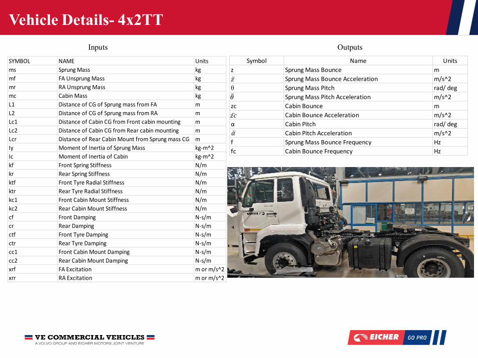
Vehicle Details- 4x2TT
SYMBOL NAME Unitsms Sprung Mass kgmf FA Unsprung Mass kgmr RA Unsprung Mass kgmc Cabin Mass kgL1 Distance of CG of Sprung mass from FA mL2 Distance of CG of Sprung mass from RA mLc1 Distance of Cabin CG from Front cabin mounting mLc2 Distance of Cabin CG from Rear cabin mounting mLcr Distance of Rear Cabin Mount from Sprung mass CG mIy Moment of Inertia of Sprung Mass kg-m^2Ic Moment of Inertia of Cabin kg-m^2kf Front Spring Stiffness N/mkr Rear Spring Stiffness N/mktf Front Tyre Radial Stiffness N/mktr Rear Tyre Radial Stiffness N/mkc1 Front Cabin Mount Stiffness N/mkc2 Rear Cabin Mount Stiffness N/mcf Front Damping N-s/mcr Rear Damping N-s/mctf Front Tyre Damping N-s/mctr Rear Tyre Damping N-s/mcc1 Front Cabin Mount Damping N-s/mcc2 Rear Cabin Mount Damping N-s/mxrf FA Excitation m or m/s^2xrr RA Excitation m or m/s^2
Symbol Name Unitsz Sprung Mass Bounce m
Sprung Mass Bounce Acceleration m/s^2θ Sprung Mass Pitch rad/ deg
Sprung Mass Pitch Acceleration m/s^2zc Cabin Bounce m
Cabin Bounce Acceleration m/s^2α Cabin Pitch rad/ deg
Cabin Pitch Acceleration m/s^2f Sprung Mass Bounce Frequency Hzfc Cabin Bounce Frequency Hz
𝑧̈
�̈�
𝑧�̈�
�̈�
Inputs Outputs
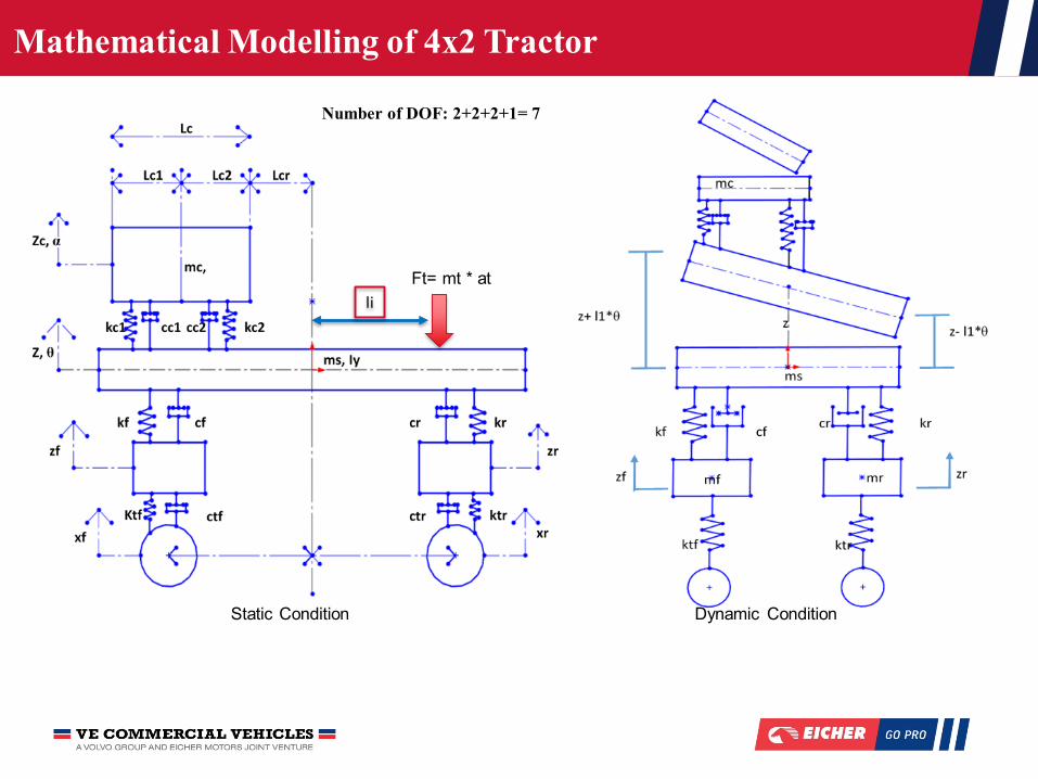
Mathematical Modelling of 4x2 Tractor
Static Condition Dynamic Condition
Number of DOF: 2+2+2+1= 7
Ft= mt * atli

Input Parameters
8
Road Input from A Class Road & 5th Wheel Coupling
Input conditions for Cement Road
Sensor Mtg. Location No. of Sensors
Front Axle 2 (LH+RH)
Rear Axle 2 (LH+RH)
Chassis- Above Front Suspension 2 (LH+RH)
Chassis- Above Rear Suspension 2 (LH+RH)
Fifth Wheel Coupling 1
Cabin Floor 1 ( Below Driver Seat)
Driver Seat 2 (Driver+ Co Driver)
Dynamic Damping

9
Damper properties of Main Suspension Parameter Estimation Tool
Parameter Estimation & Look-up Tables for Dynamic Input

10
Mathematical Modeling of Differential Equations in Simulink
Overview of Mathematical Model Mathematical Model of Cabin
Mathematical Model of Sprung Mass Mathematical Model of Seat
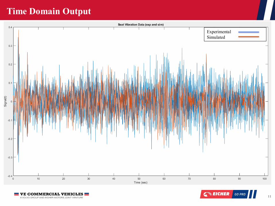
Time Domain Output
11
ExperimentalSimulated

Time Domain Output Visulaization
12
ExperimentalSimulated
Following Result shows close trend being followed by Simulation and actual result
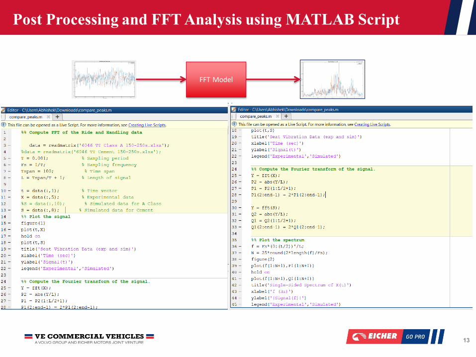
Post Processing and FFT Analysis using MATLAB Script
13
FFT Model

FFT Analysis- A Class Road
14
ExperimentalSimulated

FFT Analysis- Cement Road
15

RCI Analysis
16
0
0.05
0.1
0.15
0.2
0.25
0.3
0.35
0.4
0.45
0.5
0.55
0.6
0.65
0.7
0.75
0.8
0 2 4 6 8 10 12 14
a (r
ms)
m/s
^2
Frequency Hz
RCI Analysis
RCI-8 Hr
Cabin Actual A Class m/s
Cabin Sim A Class m/s
Cabin Actual Cement m/s
Cabin Sim Cement m/s

Conclusion & Future Scope
17
The project features Ride Comfort Establishment of Tractor Semi-Trailer Vehicle in Virtual Environment using MATLAB Simulink R2019b. The following conclusions can be obtained:
• Time Domain Simulation Showcases the model following the Actual Simulation with close proximity
• Frequency domain shows the simulation to follow the actual result between 1-5Hz.
Further Scope• Engine Level vibration as input.
• Multi Axle Input
• Full Car Model Development for Handling Analysis