development of new inductive sensor - ansys · 2016-12-13 · development of new inductive sensor...
TRANSCRIPT

Development of New Inductive Sensor
Lingmin Shao KSR International

Outline
• Introduction• Optimization of electromagnetic structure of the inductive sensor
• Boundary conditions for ASIC design• Module level simulation• Conclusion
2012 Automotive Simulation World Congress 2Monday, October 08, 2012

http://www.ksrint.com
2012 Automotive Simulation World Congress 3Monday, October 08, 2012
Inductive sensors are low‐cost and more robust in their life cycle compared to magnetic sensors.KSR initially developed its own patented inductive sensor technology for ETC pedal. Inductive sensor is further applied to suspension height, transmission , fuel level…

Current Inductive Sensor Structure
2012 Automotive Simulation World Congress 4Monday, October 08, 2012
Analog ASIC:Driving the oscillatorSignal processing
Aluminum rotor
Coils:transmitting coil (CR)receiving coil1 (RM1)receiving coil2 (RM2)
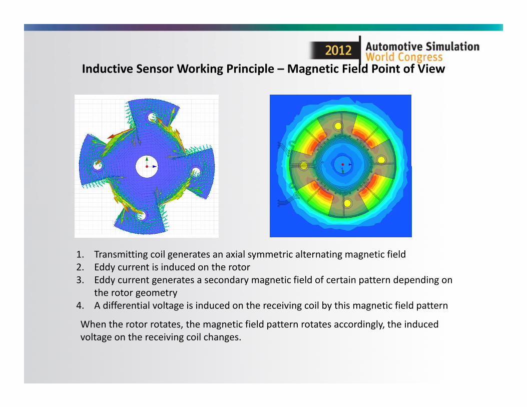
Inductive Sensor Working Principle – Magnetic Field Point of View
When the rotor rotates, the magnetic field pattern rotates accordingly, the induced voltage on the receiving coil changes.
1. Transmitting coil generates an axial symmetric alternating magnetic field2. Eddy current is induced on the rotor3. Eddy current generates a secondary magnetic field of certain pattern depending on
the rotor geometry4. A differential voltage is induced on the receiving coil by this magnetic field pattern

Why new inductive sensor technology
Input from customer:• New functionality such as digital output (SENT, PSI5);• Wider measurement range up to 360 degrees;• Smaller size;• More robustness for mechanical variation and temperature variation;• Better EMC performance;
Solution:• New DSP based ASIC to provide more functionality and better flexibility;• New electromagnetic structure to provide better electrical performance
2012 Automotive Simulation World Congress 6Monday, October 08, 2012

Challenge of new developmentDevelopment of a new ASIC costs more than $1M.ANSYS tool set used to reduce risk and speed the process of research and development
Electromagnetic structure:Improve the performance(linearity, robustness) while reducing the size;ASIC is not available to test out the design.
ASIC:Uncertainty of electromagnetic structure characteristics
‐ Impedance of electromagnetic structure‐ Raw signal strength
Module level:Integration of electromagnetic structure, ASIC and discrete components.Will it work? How much improvement can we expect?Need to be answered before building a physical part.
2012 Automotive Simulation World Congress 7Monday, October 08, 2012
Electromagnetic structure design
Requirement:1. Power efficiency ‐maximum signal strength with the given driven power2. Robustness – output should not change with the mechanical and temperature
variation
Monday, October 08, 2012 2012 Automotive Simulation World Congress 8

Transmitting coil – circuitry perspective
Design parameter: turns, pitch, width…Design Target : high Q factor
2012 Automotive Simulation World Congress 9Monday, October 08, 2012
7 turns 6 turns
0.00 2.00 4.00 6.00 8.00 10.00 12.00Freq
0.00
10.00
20.00
30.00
40.00
50.007 turnsCoil Q factor ANSOFT
Curve Info6 turns
Imported7 turns
Imported
7 turns has higher impedance, lower Q factor
PEX
ex1 ex2vhv vhv
ex1 ex2
cap
ex1:1ex1:1_ref
ex2:1ex2:1_ref
2.00 2.50 3.00 3.50 4.00 4.50 5.00 5.50 6.00F
0.00
1.25
2.50
3.75
5.00
6.25
7.50
8.75loaded Q 7 turnsImpedance ANSOFT
Curve Info6 turns
Imported7 turns
Imported

Transmitting coil – magnetic field perspective
Design Target: High magnetic field strength with given driven power
2012 Automotive Simulation World Congress 10Monday, October 08, 2012
0
ex2ex1
vhvvhvex2ex1
ex1 ex2
vhv
V1101
ex1:1ex1:1_ref
ex2:1ex2:1_ref
cap
AName=Is
AName=Itank
0.00 2.50 5.00 7.50 10.00 12.50 15.00 17.50 20.00Time
0
0
0
0
0
0
0ft LLC oscillator 7turnstank current ANSOFT
Curve Info7 turns
Imported6 turns
Imported
H field for 7 turns
6 turns has higher circulating current, it has slightly higher magnetic field strength
H field for 6 turns

Receiving coil and rotor
Design parameter: Geometry of receiving coil and rotorDesign Target: High receiving signal strength with given driven power
2012 Automotive Simulation World Congress 11Monday, October 08, 2012
Nominal size
1.2time scaled
0.8time scaled
0.00 50.25 50.50 50.75 51.00 51.25 51.50 51.75 52.00Tim e
coupler size1signal ANSOFT
Curve Infoscaled by 0.8
Importednominal size
Importedscaled by 1.2
Imported
Rotor need match with the coil size, a mismatched rotor will reduce the signal

Signal quality in real life
Signal is susceptible to variability such as geometry tolerance and temperature Design Target: sensor output should be immune to the variabilitySolution: make a pair of offset coils, the ratio of two signals will factor out the variability
For signal quality, it is only needed to solve the impedance of the electromagnetic structure.
2012 Automotive Simulation World Congress 12Monday, October 08, 2012
00
)()()()()()()()()(
)()()(
22212
21111
21
2
1
cr
sigsigsigsigsigcr
sigsigsigsigsigcr
sigcrsigcrcrcrcr I
ZZZZZZZZZ
SigSigV
)(/)()(/)()((var)*)()(
(var)*)()(
21
2
1
XffsigsigoutputgXfsig
gfsig
)()(
)(2
1
sigcr
sigcr
ZZ
output

Signal quality simulation result
2012 Automotive Simulation World Congress 13Monday, October 08, 2012
-25.00 -12.50 0.00 12.50 25.00rz [deg]
assy 6 turns xyzsignal ANSOFT
Curve Infosig1
Setup1 : LastAdaptiveFreq='0.004GHz' gap='1mm'
sig1Setup1 : LastAdaptiveFreq='0.004GHz' gap='1.25mm'
sig1Setup1 : LastAdaptiveFreq='0.004GHz' gap='1.5mm'
sig2Setup1 : LastAdaptiveFreq='0.004GHz' gap='1mm'
sig2Setup1 : LastAdaptiveFreq='0.004GHz' gap='1.25mm'
sig2Setup1 : LastAdaptiveFreq='0.004GHz' gap='1.5mm'
-25.00 -12.50 0.00 12.50 25.00rz [deg]
assy 6 turns xyzoutput ANSOFT
Curve Infooutput
Setup1 : LastAdaptiveFreq='0.004GHz' gap='1mm'
outputSetup1 : LastAdaptiveFreq='0.004GHz' gap='1.25mm'
outputSetup1 : LastAdaptiveFreq='0.004GHz' gap='1.5mm'
Two raw signals change significantly with the air gap
The ratio of two raw signals does not change with the air gap

ASIC design boundary
2012 Automotive Simulation World Congress 14Monday, October 08, 2012
ASIC
Analog interface DSP
Signal
power
Electrical characteristic for oscillator driver design; Signal range for amplifier and ADC design; Signal quality for DSP calibration algorithm

SPICE model is the communication tool
2012 Automotive Simulation World Congress 15Monday, October 08, 2012
chpdisck_dspcosinecr_mon
errex1ex2gdgdcgdengsel3gsel2
gsel1gsel0hbtlbt
poerm1rm2sinevddvgvhv
vhv_in
ex1:1ex1:1_ref
ex2:1ex2:1_ref
rm1:1rm1:1_ref
rm2:1rm2:1_ref
HFSS model
Coil design environment
chpdisck_dspcosinecr_mon
errex1ex2gdgdcgdengsel3gsel2
gsel1gsel0hbtlbt
poerm1rm2sinevddvgvhv
vhv_in
ex1:1_posex1:1_negex2:1_posex2:1_neg
rm1:1_posrm1:1_negrm2:1_posrm2:1_neg
ASIC design environment
Full wave SPICE model
inputinput
Typical and worst case of the electromagnetic structure is extracted to full wave SPICE model as the design boundary of the ASIC;ASIC can be imported to designer for validation;Two components can be designed in parallel.

Module level simulation
2012 Automotive Simulation World Congress 16Monday, October 08, 2012
0 0
0
ex2
ex1
ex2
rm1
rm2
vhv
vhv
vhv
ex1
gdengdc
GD
GD
poelbthbt
err
ck_dsp
cr_mon
vdd
vhv_in
chpdis
vhvvg
rm1rm2
cos
sinex2ex1
cap cap
cap
V2100
AIvhv
AIex1
chpdisck_dspcosinecr_mon
errex1ex2gdgdc
gdengsel3gsel2
gsel1gsel0hbtlbt
poerm1rm2sinevddvgvhv
vhv_in
ex1:1ex1:1_ref
ex2:1ex2:1_ref
rm1:1rm1:1_ref
rm2:1rm2:1_ref
Larger gap need more circulating current
Larger gap consume more power
Signal strength remains same at different gap
90.00 292.00 294.00 296.00 298.00 300.00Time
moduleCurrent draw ANSOFT
Curve InfoIpositive(Ivhv)
Transientcap='820pF' gap='1mm' rz='0deg'
Ipositive(Ivhv)Transientcap='820pF' gap='1.5mm' rz='0deg'
90.00 292.00 294.00 296.00 298.00 300.00Time
moduleCR current ANSOFT
Curve InfoIpositive(Iex1)
Transientcap='820pF' gap='1mm' rz='0deg'
Ipositive(Iex1)Transientcap='820pF' gap='1.5mm' rz='0deg'
290.00 292.00 294.00 296.00 298.00 300.00Time
moduleraw signal ANSOFT
Curve InfoV(rm2)
Transientcap='820pF' gap='1mm' rz='0deg'
V(rm2)Transientcap='820pF' gap='1.5mm' rz='0deg'
25.00 -12.50 0.00 12.50 25.00rz [deg]
moduletransfer function ANSOFT
Curve Infomean(output)
Transientgap='1mm'
mean(output)Transientgap='1.5mm'
Transfer function remains same at different gap

Test result
Monday, October 08, 2012 2012 Automotive Simulation World Congress 17
0
20
40
60
80
100
150 200 250 300
Output vs. angle
X=0 Y=‐0.6 Z=1.1
X=0 Y=0 Z=1.1
X=0 Y=0.6 Z=1.1
X=‐0.6 Y=0 Z=1.1
X=0.6 Y=0 Z=1.1
X=0 Y=0 Z=1.7
X=0 Y=0 Z=0.5
‐1
‐0.5
0
0.5
1
150 200 250 300
Linearity vs. angle
X=0 Y=0 Z=1.1
X=0 Y=‐0.6 Z=1.1
X=0 Y=0.6 Z=1.1
X=‐0.6 Y=0 Z=1.1
X=0.6 Y=0 Z=1.1
X=0 Y=0 Z=1.7
For +/‐0.6mm variation in 3 axis, linearity is +/‐0.3%;From ‐40°C to 125°C, output change less than 0.3%

Improvement
• 30% area reduction;• Range of measurement increases from 70 degree to 180 degree with better
linearity;• Allow double mechanical tolerance;• Programmable transfer function;• Support PSI5 and SENT digital output.
Monday, October 08, 2012 2012 Automotive Simulation World Congress 18

Conclusion
• A large variety of electromagnetic structures can be tested quickly with the help of HFSS;
• Electrical characteristic can be extracted for circuit design in parallel;
• System level validation can be done in designer before prototype;
• Simulation has good correlation with the measurement;• A new generation inductive sensor has been developed in controlled time and with lower risk.
Monday, October 08, 2012 2012 Automotive Simulation World Congress 19