development of new anti-corrosion method (iecos) for ... · many marine steel structures, such as...
TRANSCRIPT

Vo l . 41 No . 2 Augus t 2008
58
1. IntroductionMany marine steel structures, such as harbor and oil exploration facilities, were constructed in the high economic growth period in the 1960s, and are aged 40 years or more. Since the steel products used in these structures have been corroding, the number of aging structures is expected to increase rapidly. However, it is expensive to renovate or modify these structures. In recent years, therefore, it has been necessary to extend the service life of the existing structures by appropriately maintaining and managing them as the f inancial situation surrounding infrastructure has become increasingly severe. (1), (2) Moreover, the scale of newly constructed marine steel structures has been continuing to grow, and the service life of these structures is continuing to lengthen (50 to 100 years). Therefore, the development of a new anti-corrosion technology superior in terms of life cycle cost is required. (3)
In order to establish a new anti-corrosion method that provides excellent anti-corrosion and cost performance, we have adopted the IHI Electrocoating System (IECOS : hereinafter IECOS) (4), (5) that was originally developed for ships and vessels as a new anti-corrosion method for marine steel structures. This paper summarizes the IECOS method.
2. Characteristics of the IECOS methodGenerally, the cathodic protection method (galvanic type) using Al alloy, which can be easily maintained and managed , has been appl ied to protec t t he underwater par ts of marine steel structures from corrosion. It has been reported that when the cathodic protection method (galvanic type) is applied to marine steel structures, a thin calcareous deposit is formed on the surface of the steel product as a by-product, which requires less protective current density, and improves protective current distribution. (6), (7) Recently, the electro-deposition method has emerged, where a current is artificially applied to a marine steel structure using an external power source to form a calcareous deposit with a thickness that cannot be achieved by cathodic protection, and that protects the structure from corrosion. (8) However, the electro-deposition method q requires a longer construction period in order to increase the coating thickness, and w makes it more difficult to inspect and diagnose the structure after construction, and therefore has not been generally applied. For these reasons, we studied the application of the IECOS method where the electro-deposition and cathodic protection methods are combined. From the standpoint of the cathodic protection method, protective current density can be reduced by forming a calcareous deposit, enabling a low-cost cathodic protection design. On the other hand, from
Development of New Anti-Corrosion Method (IECOS)
for Marine Steel Structures
SUZUKI Yasunobu : Production Technology Development Department, Production Engineering Center, Corporate Research & Development
AKAMINE Kenichi : Doctor of Engineering, Manager, Production Technology Development Department, Production Engineering Center, Corporate Research & Development
KANESAKA Kaoru : Development Department, Infrastructure Division, Logistics Systems & Structures
IMAZEKI Masanori : Manager, Development Department, Infrastructure Division, Logistics Systems & Structures
Marine steel structures are important infrastructures, so effective anti-corrosion methods are essential for maintenance management. IHI has developed a new anti-corrosion method, IECOS, which consists of two methods, “Electro-deposition” and “Cathodic protection.” IECOS can achieve a long-lasting service life by providing super-long-term anti-corrosion for the marine structures. In the first stage of application, the electro-deposition film is increased to adequate thickness with an external electric power supply. As a result, the required current density for corrosion protection can be sharply reduced compared with the conventional cathodic protection method. IECOS was confirmed to be an excellent anti-corrosion method by tank tests and marine tests applied to steel pipe piles.

59
Vo l . 41 No . 2 Augus t 2008
the standpoint of the electro-deposition method, the coating thickness can be reduced, thus reducing the time required for forming the calcareous deposit, and can provide easier maintenance and management in combination with the cathodic protection method. Table 1 shows the comparison of the characteristics of the IECOS method with those of conventional anti-corrosion methods. Figure 1 brief ly explains how an electro coating is formed. A calcareous deposit is formed by applying current to the steel product side to increase the pH of the surface of the steel product. When the pH increases, Ca2+ and Mg2+ contained in seawater is converted into CaCO3 and Mg (OH)2, which is deposited and attached onto the surface of the steel product. (6), (7), (10), (11) H2O + 1/2O2 + 2e- → 2OH- ............................... (1)or, 2H2O + 2e- → 2OH- + H2
................................. (2) OH- + HCO3
- → H2O + CO32- ........................... (3)
CO32- + Ca2+ → CaCO3
..................................... (4)and, 2OH- + Mg2+ → Mg(OH)2
................................ (5) The IECOS method, which was developed focusing on this phenomenon, is an anti-corrosion method where a current is initially applied using an external power source to form a calcareous deposit in a short time and reduce the protective current density required for cathodic protection. This paper reports on the study on the calcareous deposit thickness when the IECOS method is applied with cathodic protection in Chapter 3, as fundamental research, and the study on the applicability of the IECOS method in the circulation test cell in Chapter 4, and introduces the marine test in Chapter 5 and an example application in an actual environment in Chapter 6.
3. Study on calcareous deposit thickness
when used with cathodic protection (Laboratory test)
Since the IECOS method is used with cathodic protection, the relationship between the calcareous deposit thickness and protective current density needs to be clarified for appropriate corrosion protection design. Therefore, we applied cathodic protection to test pieces covered with electro coating formed under various conditions and measured the protective current density thereof. Table 2 shows the conditions under which calcareous deposits were formed. To form the various calcareous deposits, the cathode current densities were set to 0.5, 1.0, and 2.0 A/m2 to change the relative proportions of the calcareous deposits, and moreover, the durations during which electricity was applied were adjusted to change the coating thickness. After the calcareous
Atmosphere
DC power source
CO2 + H2O H2CO3 H+ + HCO 3
H2O
H2 + 2OH
CaCO3 + H2O Ca2+ + HCO3 + OH
Mg(OH)2 Mg2+ + 2OH −
−
−
− −
Calcareous deposit
Current
Seawater
2e−2e−
Fig. 1 Schematic of electrodeposit forming reaction
Cathode (steel product)
Anode
Anti-corrosion methods
Anti-corrosion mechanism
Applicable range
Service life
Construction performance
Maintenance and management
Track record
At or below M. S. L.
50 years or more (target) 20-year track recordUp to 50 years
At or below M. S. L.At or below M. L. W. L.
IECOS methodItems
Cathodic protection method (9)
(Galvanic type)Electro-deposition method (9)
The anti-corrosion effects obtained by forming a calcareous deposit and by cathodic protection supplement each other.
A protective current is applied to a metal having a higher ionization tendency to prevent metal elution and provide corrosion protection.
A calcareous deposit is formed on the surface of steel products using an external power source to isolate the steel product from the external environment (oxygen and sea water) for corrosion protection.
· The calcareous deposit is spontaneously repaired by cathodic protection when it comes off.
· Maintenance and management as required by cathodic protection are required.
· Maintenance and management have been standardized and simplified.
Limited In general use Limited
(Note) M. S. L. : Mean sea levelM. L. W. L. : Mean low water level
· A longer time (4 to 6 months) is required to increase the coating thickness (about 5 to 20 mm).
· Repair is needed when a calcareous deposit comes off.
· Detailed corrosion surveys are needed.
Table 1 Characteristics of IECOS
· The construction period is shorter than that required by the electro-deposition method.
· The number of anodes can be reduced compared with that required by the cathodic protection method.
· The design and construction methods for corrosion protection have been standardized.
Vo l . 41 No . 2 Augus t 2008
60
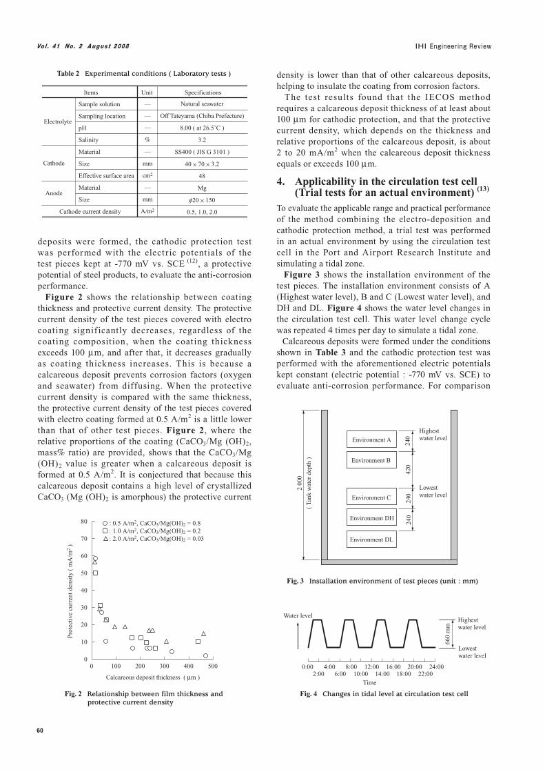
deposits were formed, the cathodic protection test was performed with the electr ic potentials of the test pieces kept at -770 mV vs. SCE (12), a protective potential of steel products, to evaluate the anti-corrosion performance. Figure 2 shows the relationship between coating thickness and protective current density. The protective current density of the test pieces covered with electro coating signif icantly decreases, regardless of the coating composition, when the coating thickness exceeds 100 μm, and after that, it decreases gradually as coating thickness increases. This is because a calcareous deposit prevents corrosion factors (oxygen and seawater) from diffusing. When the protective current density is compared with the same thickness, the protective current density of the test pieces covered with electro coating formed at 0.5 A/m2 is a little lower than that of other test pieces. Figure 2, where the relative proportions of the coating (CaCO3/Mg (OH)2, mass% ratio) are provided, shows that the CaCO3/Mg (OH)2 value is greater when a calcareous deposit is formed at 0.5 A/m2. It is conjectured that because this calcareous deposit contains a high level of crystallized CaCO3 (Mg (OH)2 is amorphous) the protective current
density is lower than that of other calcareous deposits, helping to insulate the coating from corrosion factors. The test results found that the IECOS method requires a calcareous deposit thickness of at least about 100 μm for cathodic protection, and that the protective current density, which depends on the thickness and relative proportions of the calcareous deposit, is about 2 to 20 mA/m2 when the calcareous deposit thickness equals or exceeds 100 μm.
4. Applicability in the circulation test cell (Trial tests for an actual environment) (13)
To evaluate the applicable range and practical performance of the method combining the electro-deposition and cathodic protection method, a trial test was performed in an actual environment by using the circulation test cell in the Port and Airport Research Institute and simulating a tidal zone. Figure 3 shows the installation environment of the test pieces. The installation environment consists of A (Highest water level), B and C (Lowest water level), and DH and DL. Figure 4 shows the water level changes in the circulation test cell. This water level change cycle was repeated 4 times per day to simulate a tidal zone. Calcareous deposits were formed under the conditions shown in Table 3 and the cathodic protection test was performed with the aforementioned electric potentials kept constant (electric potential : -770 mV vs. SCE) to evaluate anti-corrosion performance. For comparison
0
10
20
30
40
50
60
70
80
0 100 200 300 400 500
Calcareous deposit thickness ( μm )
Pro
tect
ive
curr
ent d
ensi
ty (
mA
/m2
)
: 0.5 A/m2, CaCO3/Mg(OH)2 = 0.8: 1.0 A/m2, CaCO3/Mg(OH)2 = 0.2: 2.0 A/m2, CaCO3/Mg(OH)2 = 0.03
Fig. 2 Relationship between film thickness and protective current density
Items Unit Specifications
Electrolyte
Cathode
Cathode current density
Anode
Sample solution
Sampling location
pH
Salinity
Material
Size
Effective surface area
Material
Size
—
—
—
%
—
mm
cm2
—
mm
A/m2
Natural seawater
Off Tateyama (Chiba Prefecture)
8.00 ( at 26.5˚C )
3.2
SS400 ( JIS G 3101 )
40 × 70 × 3.2
48
Mg
f20 × 150
0.5, 1.0, 2.0
Table 2 Experimental conditions ( Laboratory tests )
Environment A
Environment B
Environment C
Environment DH
Environment DL
240
240
420
240
2 00
0
( Ta
nk w
ater
dep
th )
Highest water level
Lowest water level
Fig. 3 Installation environment of test pieces (unit : mm)
660
mm
Lowest water level
Highest water level
Water level
Time
0:00 4:002:00
8:006:00
12:0010:00
16:0014:00
20:0018:00
24:0022:00
Fig. 4 Changes in tidal level at circulation test cell

61
Vo l . 41 No . 2 Augus t 2008
locations where they were installed, and thus show that a calcareous deposit has an anti-corrosion effect. These figures also show that the protective current density of all the test pieces decreases with time after cathodic protection starts. This is possibly because a thin calcareous deposit forms on the surfaces of the test pieces. (6), (7)
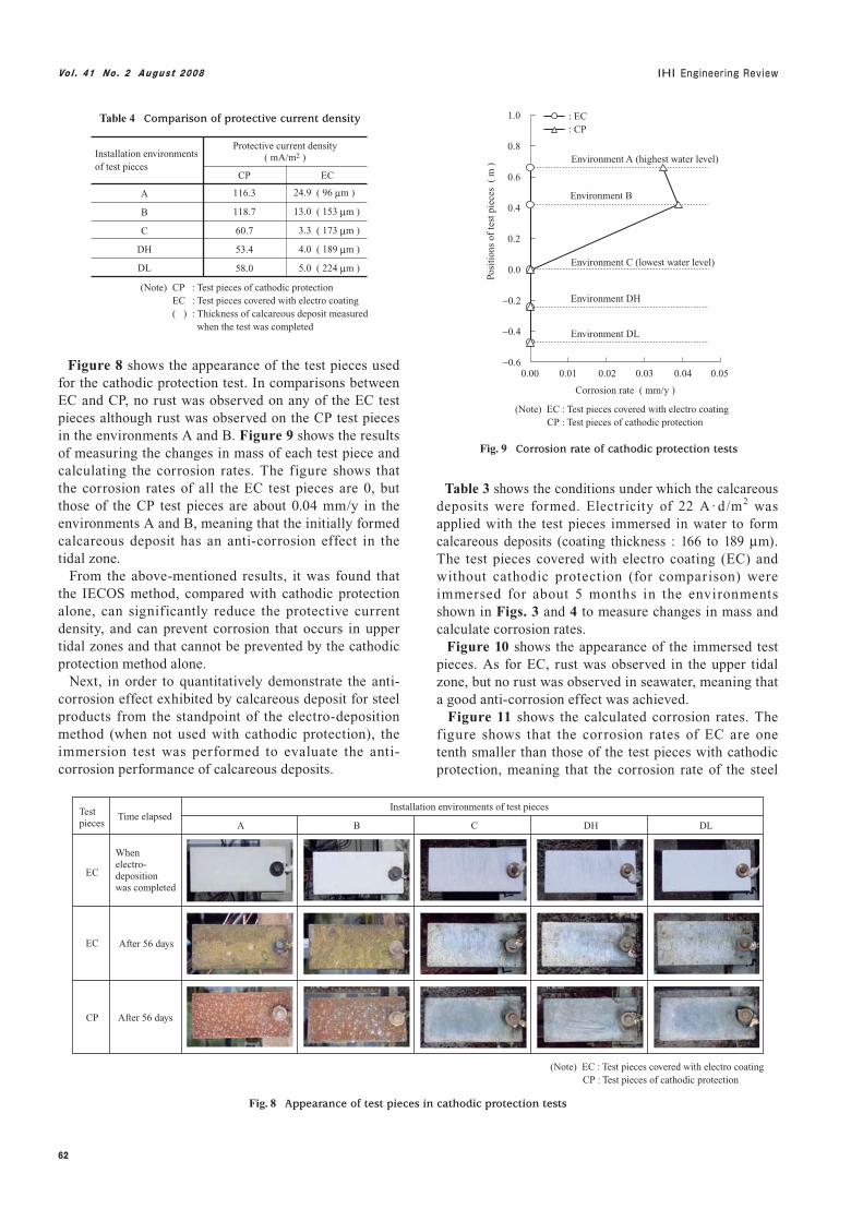
Table 4 shows the result of the comparison of the protective current density of the test pieces measured (after 56 days have passed) after being tested in each test environment. The protective current density of CP installed underwater is about 50 to 60 mA/m2, which corresponds with the reported protective current density of steel products. (9) On the other hand, the protective current density of EC is about 3 to 5 mA/m2, meaning that the protective current density can be reduced to about one tenth by initially forming a calcareous deposit.
with the test pieces on which calcareous deposits were formed by electro coating (symbols : EC, EC-A, -B, -C, -DH, -DL), cathodic protection was performed on the test pieces of cathodic protection (without calcareous deposit, symbols : CP, CP-A, -B, -C, -DH, -DL), to which conventional cathodic protection was applied and installed in the same positions in the tank. Figure 5 shows the positions where each test piece was installed. Figures 6 and 7 show the changes in the protective current density with time when test pieces covered with electro coatings (EC) and cathodic protection (CP) were installed in each environment. These figures show that the protective current density of EC (Fig. 6) is lower than that of CP (Fig. 7) regardless of the
Items Unit Specifications
Electrolyte
Cathode
Cathode current density
Installation environment of test pieces
Electricity
Anode
Sample solution
Sampling location
pH
Salinity
Material
Size
Effective surface area
Material
Size
—
—
—
%
—
mm
cm2
—
mm
A/m2
—
A·d/m2
Natural seawater
Off the shore of Kurihama (Kanagawa Prefecture)
7.94 ( at 26.5˚C )
2.8
SS400 ( JIS G 3101 )
70 × 150 × 3.2
220
Lead, silver alloy
f25 × 250
2.0
A
7.0
B, C, DH, DL
14.0
Table 3 Experimental conditions ( Trial tests under actual environment )
(a) Installation of test pieces (b) Installation in the circulation test cell
EC-AEC-A CP-ACP-A
CP-BCP-B
CP-CCP-C
CP-DHCP-DH
CP-DLCP-DL
EC-BEC-B
EC-CEC-C
EC-DHEC-DH
EC-DLEC-DL
EC-A CP-A
CP-B
CP-C
CP-DH
CP-DL
EC-B
EC-C
EC-DH
EC-DL
EC
(Note) EC, EC-*, EC-**CP, CP-*, CP-**
: Test pieces covered with electro coating: Test pieces with cathodic protection
CP
Fig. 5 Installation of each test piece
0
10
20
30
40
50
60
70
80
90
100
0 7 14 21 28 35 42 49 56
Time elapsed ( d )
(Note) EC-*, EC-** : Test pieces covered with electro coating
Pro
tect
ive
curr
ent d
ensi
ty (
mA
/m2
)
: EC-A
: EC-B
: EC-C
: EC-DH
: EC-DL
Fig. 6 Measured results of protective cathodic current density of EC
0
25
50
75
100
125
150
175
200
225
250
0 7 14 21 28 35 42 49 56
Time elapsed ( d )
Pro
tect
ive
curr
ent d
ensi
ty (
mA
/m2
)
: CP-A: CP-B: CP-C: CP-DH: CP-DL
(Note) CP-*, CP-** : Test pieces with cathodic protection
Fig. 7 Measured results of protective cathodic current density of CP
Vo l . 41 No . 2 Augus t 2008
62
Figure 8 shows the appearance of the test pieces used for the cathodic protection test. In comparisons between EC and CP, no rust was observed on any of the EC test pieces although rust was observed on the CP test pieces in the environments A and B. Figure 9 shows the results of measuring the changes in mass of each test piece and calculating the corrosion rates. The figure shows that the corrosion rates of all the EC test pieces are 0, but those of the CP test pieces are about 0.04 mm/y in the environments A and B, meaning that the initially formed calcareous deposit has an anti-corrosion effect in the tidal zone. From the above-mentioned results, it was found that the IECOS method, compared with cathodic protection alone, can significantly reduce the protective current density, and can prevent corrosion that occurs in upper tidal zones and that cannot be prevented by the cathodic protection method alone. Next, in order to quantitatively demonstrate the anti-corrosion effect exhibited by calcareous deposit for steel products from the standpoint of the electro-deposition method (when not used with cathodic protection), the immersion test was performed to evaluate the anti-corrosion performance of calcareous deposits.
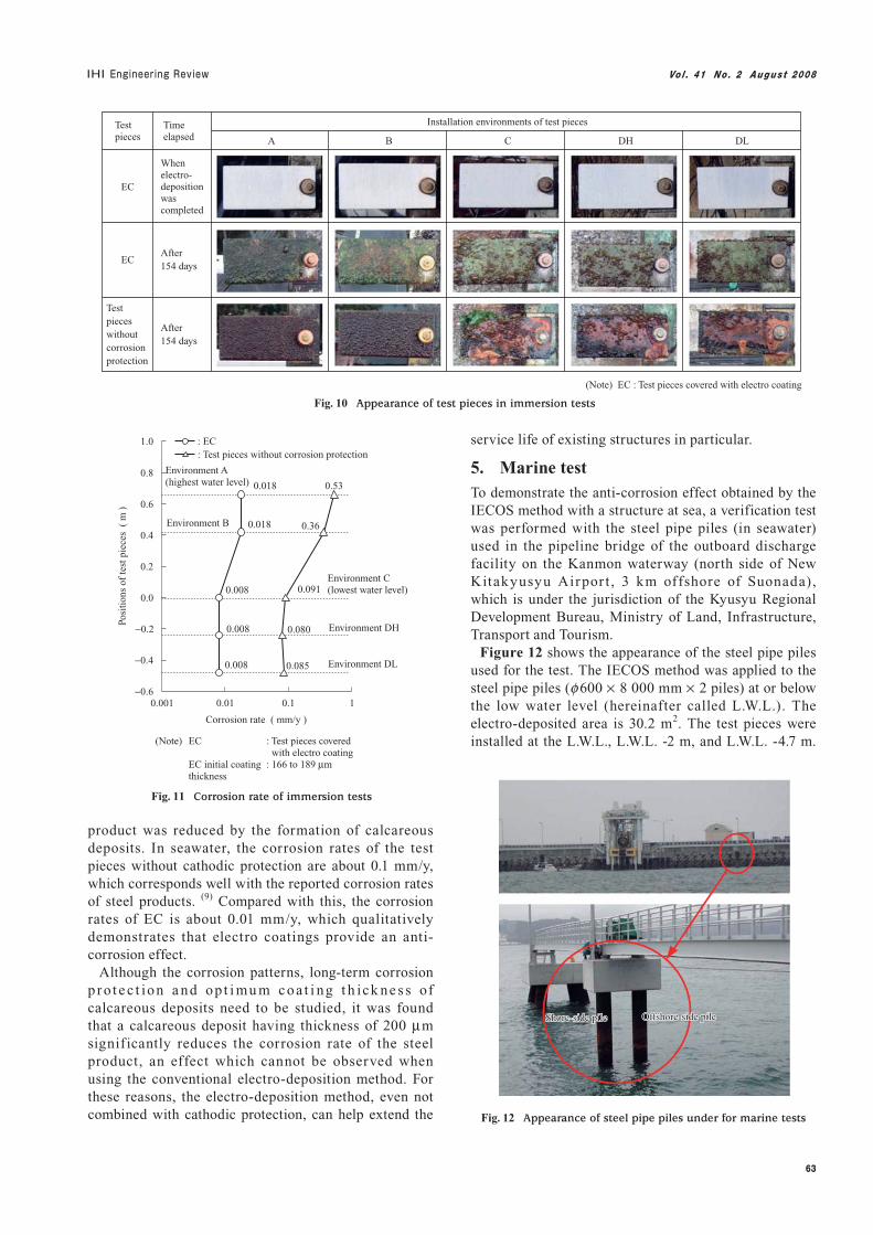
Table 3 shows the conditions under which the calcareous deposits were formed. Electricity of 22 A · d/m2 was applied with the test pieces immersed in water to form calcareous deposits (coating thickness : 166 to 189 μm). The test pieces covered with electro coating (EC) and without cathodic protection (for comparison) were immersed for about 5 months in the environments shown in Figs. 3 and 4 to measure changes in mass and calculate corrosion rates. Figure 10 shows the appearance of the immersed test pieces. As for EC, rust was observed in the upper tidal zone, but no rust was observed in seawater, meaning that a good anti-corrosion effect was achieved. Figure 11 shows the calculated corrosion rates. The figure shows that the corrosion rates of EC are one tenth smaller than those of the test pieces with cathodic protection, meaning that the corrosion rate of the steel
Installation environments of test pieces
116.3
118.7
60.7
53.4
58.0
24.9 ( 96 μm )
13.0 ( 153 μm )
3.3 ( 173 μm )
4.0 ( 189 μm )
5.0 ( 224 μm )
Protective current density( mA/m2 )
(Note) CP : Test pieces of cathodic protectionEC : Test pieces covered with electro coating( ) : Thickness of calcareous deposit measured when the test was completed
CP EC
A
B
C
DH
DL
Table 4 Comparison of protective current density
When electro-deposition was completed
After 56 days
After 56 days
Test pieces
EC
EC
CP
Time elapsed
(Note) EC : Test pieces covered with electro coating CP : Test pieces of cathodic protection
Installation environments of test pieces
A B C DH DL
Fig. 8 Appearance of test pieces in cathodic protection tests
−0.6
−0.4
−0.2
0.0
0.2
0.4
0.6
0.8
1.0
0.00 0.01 0.02 0.03 0.04 0.05
Corrosion rate ( mm/y )
Posi
tion
s of
test
pie
ces
( m
)
: EC: CP
Environment A (highest water level)
Environment B
Environment C (lowest water level)
Environment DH
Environment DL
(Note) EC : Test pieces covered with electro coating CP : Test pieces of cathodic protection
Fig. 9 Corrosion rate of cathodic protection tests
63
Vo l . 41 No . 2 Augus t 2008
product was reduced by the formation of calcareous deposits. In seawater, the corrosion rates of the test pieces without cathodic protection are about 0.1 mm/y, which corresponds well with the reported corrosion rates of steel products. (9) Compared with this, the corrosion rates of EC is about 0.01 mm/y, which qualitatively demonstrates that electro coatings provide an anti-corrosion effect. Although the corrosion patterns, long-term corrosion p ro t e c t ion a nd op t i mu m coa t i ng t h ick ne s s of calcareous deposits need to be studied, it was found that a calcareous deposit having thickness of 200 μm significantly reduces the corrosion rate of the steel product, an effect which cannot be observed when using the conventional electro-deposition method. For these reasons, the electro-deposition method, even not combined with cathodic protection, can help extend the
service life of existing structures in particular.
5. Marine testTo demonstrate the anti-corrosion effect obtained by the IECOS method with a structure at sea, a verification test was performed with the steel pipe piles (in seawater) used in the pipeline bridge of the outboard discharge facility on the Kanmon waterway (north side of New Kitakyusyu Airpor t , 3 km offshore of Suonada), which is under the jurisdiction of the Kyusyu Regional Development Bureau, Ministry of Land, Infrastructure, Transport and Tourism. Figure 12 shows the appearance of the steel pipe piles used for the test. The IECOS method was applied to the steel pipe piles (f600 × 8 000 mm × 2 piles) at or below the low water level (hereinafter called L.W.L.). The electro-deposited area is 30.2 m2. The test pieces were installed at the L.W.L., L.W.L. -2 m, and L.W.L. -4.7 m.
When electro-deposition was completed
After 154 days
After 154 days
Test pieces
EC
EC
Test pieces without corrosion protection
Time elapsed
(Note) EC : Test pieces covered with electro coating
Installation environments of test pieces
A B C DH DL
Fig. 10 Appearance of test pieces in immersion tests
0.008
0.008
0.008
0.018
0.018 0.53
0.36
0.091
0.080
0.085
−0.6
−0.4
−0.2
0.0
0.2
0.4
0.6
0.8
1.0
0.001 0.01 0.1 1
Corrosion rate ( mm/y )
Posi
tion
s of
test
pie
ces
( m
)
: EC: Test pieces without corrosion protection
Environment A (highest water level)
Environment B
Environment C (lowest water level)
Environment DH
Environment DL
Fig. 11 Corrosion rate of immersion tests
EC : Test pieces covered with electro coatingEC initial coating : 166 to 189 μmthickness
(Note)
Offshore-side pileOffshore-side pileOffshore-side pileShore-side pileShore-side pileShore-side pile
Fig. 12 Appearance of steel pipe piles under for marine tests

Vo l . 41 No . 2 Augus t 2008
64
Rust present on the surfaces of the steel pipe piles was removed by high-pressure washing, as a year has passed without cathodic protection since the construction of these piles. Figure 13 shows the overview of the electro-deposition system. Zn bars (f45 × 750 mm × 6 bars) were used as anodes to apply electricity of 35 A · d/m2 and form a calcareous deposit. The thickness of the calcareous deposit is presumed to be about 670 μm from the results of the preliminary test conducted under the same environment and conditions. To apply cathodic protection after calcareous deposit was formed, Al alloy was used as galvanic anodes at L.W.L. +2 m, L.W.L. -1 m, and L.W.L. -4 m. Figure 14 shows the appearance of the surface of the steel pipe pile in seawater. As shown in Fig. 14, no corrosion was observed on the surface of the steel pipe pile 10 months after the calcareous deposit was formed, although some marine creatures were observed on it. Figure 15 shows the result of measuring the electric potentials of the steel pipe piles. From this f igure,
it can be seen that at all the measuring points, the potentials of the steel pipe piles are -770 mV vs. SCE (12) or less, which the protective potential of steel products in seawater, meaning that corrosion protection was achieved at all the points. Table 5 shows the analytical results with the test pieces taken from the steel pipe piles. These analytical values were obtained by averaging the values obtained from the three test pieces. As for the coating composition, CaCO3/Mg (OH)2 was 0.1 when measured immediately after the calcareous deposit was formed. However, it was 1.6 to 2.0 when measured after 5 and 10 months, meaning that the coating had improved (sophisticated)
Test pieces
9.3
62.0
66.6
90.7
38.0
33.4
0.1
1.6
2.0
—
9.7
10.8
Coating composition Protective current density
( mA/m2 )CaCO3
( mass % )CaCO3
/Mg ( OH )2
Mg ( OH )2
( mass % )
Immediately after calcareous deposit formation
After 5 months
After 10 months
Table 5 Composition of calcareous deposits and protective current density
Sea
DC power source
Current
Current
Current
Current
Current
Current
Branch box– +
Steel pipe pile
Anode
Anode
Anode
Anode
Anode
Anode
Dolphin
Zn bar
Zn bar
Zn bar
Zn bar
Zn bar
Zn bar
Fig. 13 Schematic of electrodeposit system
(d) After 10 months(a) Before construction (b) Immediately after construction
(c) After 5 months
Fig. 14 Appearance of steel pipe pile surface
−7
−6
−5
−4
−3
−2
−1
0
1
2
3
Electric potential ( mV vs. SCE )
L. W. L.
Mea
suri
ng p
oint
s (
m )
: Immediately after construction (shore-side): Immediately after construction (offshore-side): After 2 months (shore-side): After 2 months (offshore-side): After 5 months (shore-side): After 5 months (offshore-side): After 10 months (shore-side): After 10 months (offshore-side)
−1 070 −1 020 −970 −920 −870 −820 −770 −720
Fig. 15 Cathodic potential of steel pipe piles

65
Vo l . 41 No . 2 Augus t 2008
containing a higher proportion of CaCO3. As performed in Chapter 3, the cathod ic protect ion tes t was performed with the electric potential kept constant (electric potential : -770 mV vs. SCE) to evaluate anti-corrosion performance. From the test result, it was found that the protective current density of the test pieces was about 10 mA/m2, and it is likely that the protective current density can be significantly reduced in the steel pipe piles. From the above-mentioned results, it was verified th rough the exter nal obser vat ion and potent ia l measurement that the steel pipe piles to which the IECOS method was applied exhibited an excellent anti-corrosive effect. Moreover, it was verified that the protective current density required for cathodic protect ion can be sign if icant ly reduced , which demonstrates the effectiveness of the IECOS method in an actual environment.
6. Application of the IECOS method to the steel pipe piles used in a jacket-type pier
A container terminal has been constructed (planned to be in service in Fall, 2008) at the Island City area in the
Port of Hakata to improve the port functions. The jacket method was adopted for the quay wall construction, and the IECOS method was applied as an anti-corrosion method to the steel pipe piles of the jacket-type pier. The overview of the construction work is as follows: Construction name Const ruction work of -15 m ber th
(earthquake-proof) at the Island City area in the Port of Hakata
Orderer Hakata Port and Airport Construction Office, Kyusyu Regional Development Bureau, Ministry of Land, Infrastructure, Transport and Tourism
Contractor T OYO - S A E K I -YO S H I DA J o i n t Venture × Ishikawajima-Harima Heavy Industr ies Co., Ltd. (presently IHI Corporation)
Construction site Fukuoka City, Fukuoka Prefecture,
Japan Structure to be constructed J2 jacket of about 1 700 m2
Figures 16 and 17 show the appearance and schematic
Structure to be constructed (J2 jacket)
Fig. 16 Appearance of structure to be constructed
qwertyu
15 0
00
Line A
Line B
L. W. L. −1 m
Area covered with stainless steel
Area to which IECOS is applied
(Note) Design water depth· Line A : −15 m· Line B : −9 m
70 000
Jacket part
Steel pipe pile
Fig. 17 Schematic of steel pipe pile jacket (unit : mm)

Vo l . 41 No . 2 Augus t 2008
66
of the structure to be constructed, respectively. The structure to be constructed is covered with seawater-resistant stainless steel above L.W.L. -1 m, and the IECOS method was applied to the area at or below L.W.L. -1 m. Grooved steel (250 × 90 × 9/13) was used as anodes to apply a current and arranged so that the current could be evenly distributed to form a calcareous deposit. Electricity of about 54 A· d/m2 was applied. After the calcareous deposit was formed, Al alloys were installed as galvanic anodes for each steel pipe pile at L.W.L. -1 m and L.W.L. -5 m for cathodic protection. Table 6 shows the design protective current density in the IECOS method. For this corrosion protection design, the service life was set to the same as that with cathodic protection, and the protective current density (submerged zone) was set to 20 mA/m2 to reduce the number of galvanic anodes. Figure 18 shows the appearances of the steel pipe pi les located in seawater. Figure 18 shows that
calcareous deposits were formed, and its thickness was 710 μm (average) when measured with an underwater film thickness meter. Figure 19 shows the result of measuring the electric potentials after the IECOS method was applied. The electric potentials of lines A and B were -770 mV vs. SCE (12) or less, which is the protective potential of steel products in seawater, meaning that corrosion protection was achieved at all the points. Moreover, the coating thickness of the test pieces installed to the jacket part met the required specifications. Construction was completed in August 2007.
7. ConclusionThe IECOS method, developed by combining the electro-deposition and cathodic protection methods, is a new anti-corrosion method for marine steel structures that reduces the design protective current density for cathodic protection and minimizes maintenance. This method is considered to be particularly effective in extending the service life of aging existing structures, the number of which is expected to rapidly increase. We will continue to collect data from the actual environment, and further improve the construction method and optimize corrosion protection design so that anti-corrosion and cost performance can be improved.
– Acknowledgements –
I would like to deeply express my gratitude to all those concerned at the Port and Airport Research Institute for providing guidance and advice regarding the performance of these tests. I also would like to thank all those concerned in the TOYO-SAEKI-YOSHIDA Joint Venture for providing much valuable advice regarding the performance of the actual construction.
Corrosive environments Unit IECOS method
mA/m2
mA/m2
20
20
100
20
Comparison with cathodic protection (9)
Submerged zone
Mud zone
Table 6 Protective current density at clean sea area (Initial value)
(a) Before construction (b) After construction
Fig. 18 Appearance of steel pipe piles immersed in seawater
Mea
suri
ng p
oint
s (
m )
: A-q
: A-w
: A-e
: A-r
: A-t
: A-y
: A-u
−14
−12
−10
−8
−6
−4
−2
0
2
Mea
suri
ng p
oint
s (
m )
−14
−12
−10
−8
−6
−4
−2
0
2 : B-q
: B-w
: B-e
: B-r
: B-t
: B-y
: B-u
(a) Line A (b) Line B
L. W. L. L. W. L.
Electric potential ( mV vs. SCE )
−1 070 −1 020 −970 −920 −870 −820 −770
Electric potential ( mV vs. SCE )
−1 070 −1 020 −970 −920 −870 −820 −770
Fig. 19 Cathodic potential after IECOS method

67
Vo l . 41 No . 2 Augus t 2008
REFERENCES
(1) S. Miyajima, Y. Asami, S. Toho and T. Sawada : An Attempt to Maintain the Harbor Facilities Based on Life Cycle Management Technique, Proceedings of Civil Engineering in the Ocean Vol.22 (2006.7) pp. 9-14
(2) E . Re i t a a nd M. Fu k a m i : A S t udy on a Su p p o r t i ng Sys t e m t o S e le c t A p p r o p r i a t e Maintenance Means for Existing Piers, Report of the Coastal Development Institute of Technology No.4 (2004.7) pp. 7-80
(3) H. Kanai and M. Ish ida : Rust Prevent ion Technology in Industries –Offshore structure–, Bosei Kanri (Rust Prevention & Control) Vol. 43 No.5 (1999.5) pp. 167-185
(4) K. Akamine : Development of New Corrosion Protection System for Ballast Water Tanks (IECOS), Bulletin of the Japan Institute of Metals Vol.38 No.1 (1999.1) pp. 49-51
(5) K. Akamine : Applicat ion of Non-Paint ing Corrosion Protection Method (IECOS) to Harbor Facilit ies, Ishikawajima-Har ima Engineer ing Review Vol.42 No.3 (2002.5) pp. 121-126
(6) G. C. Cox : Anticor rosive and Antifouling Coating and Method of Application, U.S. Patents No. 2200469 (1940.5)
(7) H. A. Humble : Cathodic Protection of Steel in
Sea Water with Magnesium Anodes Corrosion Vol.4 No.7 (1948.7) pp. 358-370
(8) M. Abe and H. Hamada : Long-term Marine Exposure Test for Cor rosion Control of Steel Pipe Piles –Field Test at Hasaki Oceanographical Research Facility–, The Foundation Engineering & Equipment Vol.28 No.12 (2000.12) pp. 40-44
(9) COASTAL DEVELOPMENT INSTITUTE OF TECHNOLOGY : Corrosion Protection and Repair Manual for Port and Harbor Steel Structures (1997.4)
(10) K. Akamine and I. Kashiki : Corrosion Protection of Steel by Calcareous Electro-deposition (Part 1) –Mechanism of Electro-deposition–, Zairyou-to-Kankyou Vol.51 No.11 (2002.11) pp. 496-501
(11) K. Akamine and I. Kashiki : Corrosion Protection of Steel by Calcareous Electro-deposition (Part 2) –Mechanism of Growth–, Zairyou-to-Kankyou Vol.52 No.8 (2003.8) pp. 401-407
(12) Japan Society for the Promotion of Science : Kinzoku Boshoku Gijutsu Binran (Metallic Corrosion Engineering Handbook), THE NIKKAN KOGYO SHIMBUN LTD. (1978.12) pp. 577-579
(13) H. Hamada, K. Kanesaka, Y. Suzuki and Y. Miyata : An Experimental Study on the Steel Corrosion Prevention Effectiveness of Combination of Electro-deposition and Cathodic Protection, Technical Note of The Port and Airport Research Institute No.1113 (2005.12) pp. 1-14