development of deployable wings for small unmanned aerial
TRANSCRIPT

Brigham Young University Brigham Young University
BYU ScholarsArchive BYU ScholarsArchive
Theses and Dissertations
2007-07-06
Development of Deployable Wings for Small Unmanned Aerial Development of Deployable Wings for Small Unmanned Aerial
Vehicles Using Compliant Mechanisms Vehicles Using Compliant Mechanisms
Steven D. Landon Brigham Young University - Provo
Follow this and additional works at: https://scholarsarchive.byu.edu/etd
Part of the Mechanical Engineering Commons
BYU ScholarsArchive Citation BYU ScholarsArchive Citation Landon, Steven D., "Development of Deployable Wings for Small Unmanned Aerial Vehicles Using Compliant Mechanisms" (2007). Theses and Dissertations. 952. https://scholarsarchive.byu.edu/etd/952
This Thesis is brought to you for free and open access by BYU ScholarsArchive. It has been accepted for inclusion in Theses and Dissertations by an authorized administrator of BYU ScholarsArchive. For more information, please contact [email protected], [email protected].

DEVELOPMENT OF DEPLOYABLE WINGS FOR SMALL
UNMANNED AERIAL VEHICLES USING
COMPLIANT MECHANISMS
by
Steven D. Landon
A thesis submitted to the faculty of
Brigham Young University
in partial fulfillment of the requirements for the degree of
Master of Science
Department of Mechanical Engineering
Brigham Young University
August 2007

Copyright © 2007 Steven D. Landon
All Rights Reserved

BRIGHAM YOUNG UNIVERSITY
GRADUATE COMMITTEE APPROVAL
of a thesis submitted by
Steven D. Landon
This thesis has been read by each member of the following graduate committee and by majority vote has been found to be satisfactory. ___________________________ ______________________________________ Date Spencer P. Magleby, Chair ___________________________ ______________________________________ Date Larry L. Howell ___________________________ ______________________________________ Date Brian D. Jensen

BRIGHAM YOUNG UNIVERSITY As chair of the candidate’s graduate committee, I have read the thesis of Steven D. Landon in its final form and have found that (1) its format, citations, and bibliographical style are consistent and acceptable and fulfill university and department style require-ments; (2) its illustrative materials including figures, tables, and charts are in place; and (3) the final manuscript is satisfactory to the graduate committee and is ready for submission to the university library. ___________________________ ______________________________________ Date Spencer P. Magleby Chair, Graduate Committee Accepted for the Department ______________________________________ Matthew R. Jones Graduate Coordinator Accepted for the College ______________________________________ Alan R. Parkinson Dean, Ira A. Fulton College of Engineering and Technology

ABSTRACT
DEVELOPMENT OF DEPLOYABLE WINGS FOR SMALL
UNMANNED AERIAL VEHICLES USING
COMPLIANT MECHANISMS
Steven D. Landon
Department of Mechanical Engineering
Master of Science
Unmanned Air Vehicles (UAVs) have recently gained attention due to their
increased ability to perform sophisticated missions with less cost and/or risk than their
manned counterparts. This thesis develops approaches to the use of compliant
mechanisms in the design of deployable wings for small UAVs. Although deployable
wings with rigid-link mechanisms have been used in the past to maintain flight endurance
while minimizing required storage volume, compliant mechanisms offer many
advantages in manufacturability and potential space savings due to function sharing of
components.
A number of compliant, deployable wing concepts are generated and a
classification system for them is formed. The pool of generated concepts serves as a
basis for stimulating future concept ideas. A methodology is also proposed for evaluating

concepts for a given application. The approach to developing compliant designs for
certain applications is illustrated through two example designs, which demonstrate key
portions of the proposed design process. Each is modeled and analyzed to demonstrate
viability.

ACKNOWLEDGMENTS
First I express thanks to my Heavenly Father for His support and the opportunities
I’ve been given in education, including this research. I thank my parents for their
encouragement and inspiration through all the years as I grow up. I also wish to thank
my wife, Melissa, for listening, for her support during the late nights and hours of
research, and for her inspiration and help with some of the prototypes.
I thank each of the members of my committee: Dr. Magleby for continually
meeting with and guiding me, Dr. Howell for giving direction and advice, and Dr. Jensen
for inspiring me to explore mechanism modeling. I also thank Dr. Jerry Bowman for his
help early in the process as I sought to understand flight principles and design objectives
for small aircraft.
I appreciatively acknowledge BYU for allowing me the use of their facilities
while building prototypes and collaborating with others. My appreciation goes to each of
the students I worked with in the lab, as well as Jon Ostler for providing pictures of his
prototype compliant airplane wing.

viii

ix
Table of Contents
Chapter 1 Introduction................................................................................................1
1.1 Background..........................................................................................................1
1.2 Motivation............................................................................................................4
1.2.1 Role of Compliant Mechanisms...................................................................5
1.3 Objective ..............................................................................................................6
1.3.1 Delimitations................................................................................................7
1.3.2 Potential Impact of the Thesis......................................................................8
Chapter 2 Literature Review ......................................................................................9
2.1 Historical Work....................................................................................................9
2.1.1 Biological Models......................................................................................10
2.1.2 Fixed-Wing Innovations ............................................................................12
2.2 Contemporary Work ..........................................................................................15
2.2.1 Early Advancements ..................................................................................16
2.2.2 Tube-Launched Missiles............................................................................17
2.2.3 Gun-Launched UAVs ................................................................................19
2.3 Compliant Wing Designs...................................................................................21
2.3.1 Fully Compliant Wings..............................................................................22
2.3.2 Compliant Mechanisms .............................................................................27
2.4 Summary ............................................................................................................32

x
Chapter 3 Methodology and Design Considerations ..............................................35
3.1 Method to be Followed ......................................................................................35
3.1.1 Concept Generation ...................................................................................35
3.1.2 Evaluation of Concepts ..............................................................................37
3.1.3 Concept Validation ....................................................................................38
3.2 Design Considerations .......................................................................................38
3.2.1 Evaluation Criteria .....................................................................................39
3.2.2 Method of Deployment ..............................................................................43
3.3 Concept Selection ..............................................................................................47
3.3.1 Criteria Prioritization .................................................................................47
3.3.2 Concept Screening .....................................................................................49
Chapter 4 Motion Types............................................................................................51
4.1 Linear Motions...................................................................................................52
4.1.1 Sliding........................................................................................................52
4.1.2 Telescoping ................................................................................................53
4.2 Planar Motions ...................................................................................................54
4.2.1 Rolling........................................................................................................55
4.2.2 In-Plane Bending .......................................................................................58
4.2.3 Revolving...................................................................................................59
4.3 Spatial Motions ..................................................................................................62
4.3.1 Twisting .....................................................................................................62
4.3.2 Crumpling ..................................................................................................64
4.3.3 Hybrids.......................................................................................................65

xi
4.4 Other Considerations .........................................................................................67
4.4.2 Material Properties.....................................................................................68
Chapter 5 Demonstration of Method .......................................................................71
5.1 Example: Compliant Rotating Locking Joint ...................................................71
5.1.1 Screening....................................................................................................72
5.1.2 Concept Selection ......................................................................................77
5.1.3 Modeling....................................................................................................79
5.1.4 Bistability...................................................................................................84
5.1.5 Locking Characteristic ...............................................................................86
5.1.6 Manufacturability.......................................................................................91
5.1.7 Summary ....................................................................................................92
5.2 Example: The IRIS ...........................................................................................93
5.2.1 Background................................................................................................94
5.2.2 Customer Needs .........................................................................................94
5.2.3 Needs and Specifications ...........................................................................95
5.2.4 Evaluation and Selection............................................................................96
5.2.5 Analysis......................................................................................................98
5.2.6 Results......................................................................................................104
Chapter 6 Conclusions.............................................................................................107
6.1 Conclusions......................................................................................................107
6.2 Recommendations for Future Work.................................................................109
6.2.1 Energy Storage and Actuation .................................................................109
6.2.2 Locking Mechanisms ...............................................................................109

xii
6.2.3 Off-axis stiffness......................................................................................110
6.2.4 Additional Validation...............................................................................110
Appendix: Actuation Methods.....................................................................................111
References.......................................................................................................................113

xiii
List of Tables
Table 3-1. Relationship between Energy Storage and Required User Input. The arrows indicate the region that tends to be promising for most situations........................................................................................................46
Table 3-2. Prioritized Design Considerations...................................................................48
Table 3-3. Screening Matrix Template. H=High, M=Medium, L=Low. A classification of motion types is discussed in detail in the next chapter. ......49
Table 5-1. Screening Matrix for appropriate motion type. ...............................................73
Table 5-2. Concept Scoring Matrix ..................................................................................79
Table 5-3. Functional specifications, derived by assigning..............................................95
Table 5-4. Screening Matrix. H=High, M=Medium, L=Low..........................................96
Table 5-5. Concept Scoring Matrix, an objective method for determining ......................97
Table 5-6. Definitions and values for variables used in calculating lift distribution........99

xiv

xv
List of Figures
Figure 1-1. Lockheed Martin’s “Desert Hawk” (left) and MLB’s “Bat” (right). ...............2
Figure 1-2. Aerovironment’s “Raven,” used during recent operations in Afghanistan......................................................................................................2
Figure 2-1. (a) Early sketches of flexible wing concepts for human flight, from Leonardo DaVinci’s papers. (b) Comparison to an actual bat wing. ...........10
Figure 2-2. A Leonardo DaVinci sketch of the harness for an ornithopter design...........11
Figure 2-3. Folding action of a bird wing, from [9]..........................................................11
Figure 2-4. (a.) Edward Frost’s Ornithopter, and (b) Clement Ader’s “Avion III” on display in Paris, circa 1900............................................................................12
Figure 2-5. Pictures from the U.S. patents for (a) Osborne’s folding-wing .....................12
Figure 2-6. (a) USS Formidable, with Vought Corsairs behind and Grumman Avengers in the foreground, 1945. (b) Folding the wings back on a Grumman TBF Avenger, 1944. [12] .............................................................13
Figure 2-7. USS Lexington, with 20 Grumman F4F Wildcats on deck. [12]...................14
Figure 2-8. The M2 submarine, just after launch of the Peto biplane fighter. [13] ..........14
Figure 2-9. (a) Japan’s Seiran floatplane from WWII. (b) Side view of the folded wing and tail configurations. [14] .................................................................15
Figure 2-10. (a) Military launcher for Jim Walker’s model glider, Fort Lewis, 1943. Two model airplanes can be seen faintly in the sky. (b) Image from Walker’s 1940 patent. [15] ............................................................................16
Figure 2-11. Post-WWII deployable wing planes. (a) Douglas A-3 Skywarrior, U.S. Navy [16]; (b) Shadow [17] and (c) Mustang II [18] private craft. ......17

xvi
Figure 2-12. (a) TOW launched in Okinawa. (b) Predator SRAW (short range anti-tank weapon) missile used in Operation Iraqi Freedom (courtesy Lockheed Martin). .........................................................................................18
Figure 2-13. Tube-launched missile from an FEA analysis [7], showing the inner deployment mechanism for the wings. ..........................................................18
Figure 2-14. (a) CAD rendering of the WASP II flyer in its stored and deploying configurations. (b) Image of the deployed WASP flyer. [22] .....................19
Figure 2-15. “Tiny Tiger” concept, from a RAN presentation, July 2003. [24]...............21
Figure 2-16. The flexible composite airframe built by the USAF and University of Florida. [25]...................................................................................................23
Figure 2-17. The airframe is stored by (a) bending the wings down and (b) curling them around the fuselage. [25] ......................................................................23
Figure 2-18. Inflatable wing patent assigned to Wayne Sebrell, 1976. [27] ....................24
Figure 2-19. The Goodyear Inflatoplane in flight.............................................................25
Figure 2-20. Deployment sequence for NASA’s I2000 inflatable glider. ........................25
Figure 2-21. (a) Vertigo’s “GLOV.” (b) Sequenced photos of deployment....................26
Figure 2-22. (a) Wing cross-section for UK’s inflatable wing, (b) Illustration of wing control through actuated flexure, and (c) ILC Dover’s complete inflatable wing craft.......................................................................................27
Figure 2-23. The small-length flexural pivot and its corresponding pseudo-rigid body model, from [8].....................................................................................29
Figure 2-24. The cross-axis flexural pivot, a compliant mechanism that performs the same function as a pin joint and torsional spring. [34]............................30
Figure 2-25. (a) The basic split-tube revolute joint, with (b) an illustration of its range of motion..............................................................................................31
Figure 2-26. (a) The compliant translational and (b) Compliant revolute joints. [39] .....31
Figure 2-27. Compound joints: (a) compliant universal and (b) compliant spherical joint. [39] .......................................................................................................32
Figure 4-1. Classification System for Deployable Wing Motion Types. .........................51

xvii
Figure 4-2. (a) Profile view of the two wing halves sliding by each other within the fuselage section. (b) Angled view showing the two stacked wing halves. ............................................................................................................53
Figure 4-3. Concept drawing for a telescoping wing (a) deployed and (b) retracted. ......53
Figure 4-4. Stacking three compliant telescoping systems for a full wing assembly. ......54
Figure 4-5. A compliant counterpart for telescoping motion. (a) By depressing the wing tip, the compliant wing spars allow it to (b) collapse and (c) move inside itself.....................................................................................................54
Figure 4-6. A segmented rolling wing, shown rolling up without a second layer for stiffening........................................................................................................56
Figure 4-7. A cross-sectional view from the leading edge, showing the length of the wing with opposing rolling directions for the top and bottom layers............56
Figure 4-8. Wingtip view of a sample locking mechanism for two rolling layers of a segmented rolling wing...............................................................................57
Figure 4-9. Profile view looking into the leading edge of a continuous rolling wing in its in-flight (above) and stable (below) configurations. ............................57
Figure 4-10. Bi-stable arched metal strip used in slap bracelets. By deflecting the center of the strip (a), it collapses into its other (coiled) stable equilibrium position.......................................................................................58
Figure 4-11. Top view of a wing bent back within a plane (a) before and (b) after bending. .........................................................................................................58
Figure 4-12. Hardware demonstrating in-plane bending of a wing. The model uses 5 mm thick polypropylene rods pinned to a wooden block...........................59
Figure 4-13. All motion for this bent-back wing occurs within the original wing plane. .............................................................................................................59
Figure 4-14. One wing folded over and one wing under the fuselage, using a series of living hinges for the joint. .........................................................................60
Figure 4-15. (a) One-piece and (b) two-piece rotating wing. ...........................................61
Figure 4-16. (a) Prototype of a CAFP as a pin joint for wing rotation, with detail views in the (b) relaxed and (c) stressed configurations. ..............................61

xviii
Figure 4-17. A doubling-over folding wing design. The wings are twisted and folded over, similar to an automotive windshield cover. ..............................63
Figure 4-18. The tucking wing simulates biological wings that twist and tuck back against the body. ............................................................................................64
Figure 4-19. “Plain Jane” commercial toy plane using tucking motion, shown in two steps. .......................................................................................................64
Figure 4-20. Fabric wing prototype, (a) rigidized by thin rods inserted between the fuselage and winglet. When removed (b and c), the wing occupies negligible volume. .........................................................................................65
Figure 4-21. A hybrid folding and tucking wing concept.................................................65
Figure 4-22. In-plane bending prototype from Figure 4-11 with airfoil-shaped ribs added. Rib action during deployment is illustrated in Figure 4-23. .............66
Figure 4-23. Detailed view of the motion for the prototype shown above. (a) Top view shows the feet which keep the rib upright. (b) As the flexible segments move inward, the rib begins to fall. (c) In the final position, the rib lies flat against the supporting segments............................................66
Figure 5-1. The cross-axis flexural pivot. [34] .................................................................74
Figure 5-2. (a) Prototype of a CAFP as a pin joint for wing rotation, showing one half of the full 1-piece wing. (b) Detail view of the deployed and (c) stored configurations. ....................................................................................74
Figure 5-3. Compliant slider-crank five-bar mechanism..................................................76
Figure 5-4. Slider-crank concept for wing deployment, in the (a) deployed, (b) sliding, and (c) stored configuration..............................................................76
Figure 5-5. Bistable joint concept with reduced footprint ................................................77
Figure 5-6. Motion of the concept from Figure 5-5 in the (a) deployed, (b) transition, and (c) stored configurations. .......................................................77
Figure 5-7. (a) Compliant and (b) psedudo-rigid-body models for a fixed-guided beam, from [8]. ..............................................................................................80
Figure 5-8. (a) Rigid-body model and (b) compliant representation of a bistable double-slider, from [44].................................................................................81
xix
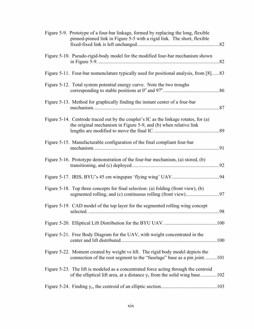
Figure 5-9. Prototype of a four-bar linkage, formed by replacing the long, flexible pinned-pinned link in Figure 5-5 with a rigid link. The short, flexible fixed-fixed link is left unchanged..................................................................82
Figure 5-10. Pseudo-rigid-body model for the modified four-bar mechanism shown in Figure 5-9. .................................................................................................82
Figure 5-11. Four-bar nomenclature typically used for positional analysis, from [8]. .....83
Figure 5-12. Total system potential energy curve. Note the two troughs corresponding to stable positions at 0o and 97o. ............................................86
Figure 5-13. Method for graphically finding the instant center of a four-bar mechanism. ....................................................................................................87
Figure 5-14. Centrode traced out by the coupler’s IC as the linkage rotates, for (a) the original mechanism in Figure 5-9, and (b) when relative link lengths are modified to move the final IC. ....................................................89
Figure 5-15. Manufacturable configuration of the final compliant four-bar mechanism. ....................................................................................................91
Figure 5-16. Prototype demonstration of the four-bar mechanism, (a) stored, (b) transitioning, and (c) deployed. .....................................................................92
Figure 5-17. IRIS, BYU’s 45 cm wingspan ‘flying wing’ UAV......................................94
Figure 5-18. Top three concepts for final selection: (a) folding (front view), (b) segmented rolling, and (c) continuous rolling (front view)...........................97
Figure 5-19. CAD model of the top layer for the segmented rolling wing concept selected. .........................................................................................................98
Figure 5-20. Elliptical Lift Distribution for the BYU UAV. ..........................................100
Figure 5-21. Free Body Diagram for the UAV, with weight concentrated in the center and lift distributed.............................................................................100
Figure 5-22. Moment created by weight vs lift. The rigid body model depicts the connection of the root segment to the “fuselage” base as a pin joint. .........101
Figure 5-23. The lift is modeled as a concentrated force acting through the centroid of the elliptical lift area, at a distance yc from the solid wing base. ............102
Figure 5-24. Finding yc, the centroid of an elliptic section.............................................103

xx
Figure 5-25. Top layer prototype (a) laid flat, (b) with one wing rolled under, and (c) with both wings rolled under. ................................................................104
Figure A-1. A sample light-activated memory plastic, from [50]. ................................112

1
Chapter 1 Introduction
Unmanned Air Vehicles (UAVs) have recently gained attention due to their
increased ability to perform sophisticated missions with less cost and/or risk than their
manned counterparts. This thesis develops approaches to facilitate use of compliant
mechanisms in the design of deployable wings for small UAVs. While deployable wings
with rigid-link mechanisms have been used in the past to maintain flight endurance while
minimizing required storage volume, compliant mechanisms offer many advantages in
manufacturability and potential space savings due to function sharing of components. A
number of compliant wing concepts will be generated and a classification system formed
as a basis for generating additional concepts. A methodology is also proposed for
evaluating concepts for a given application, with two examples serving to illustrate key
portions of the process.
1.1 Background
Many companies have started manufacturing small UAVs (SUAVs) with
wingspans under 6 ft and flight durations of over 60 minutes. These SUAVs typically
stream infrared or video surveillance back to a ground station and feature some type of
autonomous flight capability based on GPS waypoints. Examples are Lockheed’s Desert
Hawk, the Bat made by MLB, and Aerovironment’s Raven, a 4 ft wingspan SUAV used

2
by the U.S. Army in Afghanistan and Iraq during operations in 2004-2006 (see Figure 1-1
and Figure 1-2).
Figure 1-1. Lockheed Martin’s “Desert Hawk” (left) and MLB’s “Bat” (right).
Figure 1-2. Aerovironment’s “Raven,” used during recent operations in Afghanistan.
Large UAVs, like Grumman’s Global Hawk or General Atomics’ Predator first
gained broad acceptance in military applications. The CIA has used armed Predator
UAVs to destroy terrorist targets, such as Qaed Senyan al-Harthi in 2002.
The U.S. Special Operations Command, among others, has recently announced
plans to focus on rucksack-portable SUAVs (5-6 lb) as the next lightweight small tactical
platform, providing new technologies as they mature and reducing the logistics and
training required of operators. [1]

3
Advances in technology are allowing SUAVs to be used in many other
applications, such as search and rescue, border patrol, pipeline surveillance, forestry, and
law enforcement. The Los Angeles County Sheriffs Department and Police Departments
currently use a combined 35 helicopters, with 3 of them in the air on constant patrol
every day. The L.A. County Sheriffs Department was the first law enforcement agency
to purchase and test SUAVs for use—from Chang Industries in early 2005, and again
from Ocatron in 2006. [2, 3] According to Commander Sid Heal, director of technology
evaluation for the department, helicopters are too noisy and often unavailable where
needed. In contrast to the prevalent large UAVs currently in use, Commander Heal is
especially interested in SUAVs that are quiet, lightweight, portable, autonomous, and
easy for a novice to use. [4]
In the U.S. an estimated $150 million per year would be saved by law
enforcement agencies alone by using SUAVs to replace standard surveillance flights. [5]
It is estimated that by 2014 annual sales for all UAVs will exceed $13 billion. [6] To
date, the majority of those sales are large UAVs only.
UAVs offer advantages in both cost savings and enhanced performance. The
following list highlights benefits associated with UAV use, particularly for small UAVs.
Cost Savings
• Reduced personnel (one person can control flight and monitor the streamed EO or
IR images)
• Reduced training (user-friendly autopilot interfaces are often straightforward and
intuitive)
• Reduced maintenance (SUAVs can be disposable and often have few serviceable
or moving parts)

4
Enhanced Performance
• Increased field of view (foot soldiers are able to see over hills or around
buildings, using equipment that fits in a personal rucksack)
• Less detectability (quieter and smaller than standard aircraft, often battery-
operated)
• Lower risk (human life is not at risk)
• Capability in harsh conditions (no toll taken on a human pilot in high-g turns,
prolonged flights, or dangerous environments)
Nevertheless, for most SUAVs, flight endurance is still impacted by the weight
and limited life of batteries. Deployable wings thus offer the additional benefit of
providing greater wingspan to increase flight endurance without sacrificing portability or
increasing required storage space. This is discussed further in the following section.
1.2 Motivation
Some of the inherent challenges UAVs face can be addressed through the use of
deployable wings. In turn, compliant mechanisms offer potential advantages that could
be used to make deployable wings even more compact, manufacturable, and
maintainable.
1.2.1 Challenges for UAVs
For a given power source, UAV flight endurance is directly related to wing span.
Smaller wingspans decrease a craft’s range but increase versatility for specialized
situations. Thus there is an inherent trade-off between range and portability.
Surveillance applications usually call for increased range, but current SUAV systems

5
with flight endurance of greater than one to two hours are too bulky for one-man
transport. For many applications a one-man portable system is ideal.
Deployable wings offer increased wingspan and flight duration while decreasing
required space for the stored configuration. The key goal of deployable wings is to
achieve a SUAV system with a large enough wingspan to offer long endurance flights,
but that easily folds down to a one-man portable size. These SUAVs could be carried in
a briefcase, backpack, or the storage area of a personal vehicle. The ideal SUAV would
also deploy with little effort and remain deployed reliably during flight.
Many larger folding wing aircraft have relied on a complicated system of pin
joints, swivels, hinges, cables, and locks in order to provide sufficient range of motion
and stability for the folding wings. Other applications, like foldable fins for tube-
launched missiles often rely on similarly complicated systems. [7] With limited weight
and space for SUAVs, conventional rigid-body folding mechanisms have been even more
difficult to achieve. In such cases, compliant mechanisms offer many potential
advantages.
1.2.2 Role of Compliant Mechanisms
Compliant mechanisms can be used to facilitate additional space and cost savings
due to a potential reduction in part count and increased function-sharing among parts. [8]
A single compliant member may replace the springs, beams, and joints of its rigid-body
counterpart, simultaneously providing the means for structural support and motion of the
wing. This is particularly attractive for SUAVs because function sharing and reduced
part count lead to weight savings, allowing greater range for a given power supply.

6
A second benefit to compliant members is the energy storage inherent in their
deflection. Unlike rigid-body mechanisms, which achieve their motion from kinematic
pairs, or joints allowing motion in one or more directions, the members in compliant
mechanisms may provide energy storage along with their motion.
Reduced wear and lubrication are a third advantage. Replacing bearings or pin
joints with flexible members not only reduces part count and costs, but eliminates much
of the future maintenance otherwise required.
Compliant mechanisms also introduce inherent challenges. Many compliant
members are designed only for small deflections so as to avoid creep, yielding, or fatigue.
For deployable wings, however, large-scale motion may be necessary to maximize
reduction of the wingspan. Material properties will influence wing mechanism behavior
and create additional tradeoffs. Many materials undergo stress relaxation, or “memory
effect,” never returning fully to the undeflected position. Other materials like aluminum,
titanium, or steel add weight and may be limited to a smaller range of motion before
yielding.
1.3 Objective
It has been shown that there is a demand for SUAVs with deployable wings and
that compliant mechanism technologies offer promising benefits in this field. At the
same time, relatively little work has been done to advance compliant deployable wings.
Most folding wing designs use rigid-body concepts and vary little from early designs,
leaving engineers a narrow band of concepts from which to draw. Additionally,
evaluation criteria are necessary for a systematic approach to selecting the best concept
for a given application.

7
This thesis will result in a small group of alternative concepts for deployable
wings using compliance, a classification system for deployable wings, and a method for
evaluating folding wing designs for a given application. Collecting and categorizing
compliant designs will aid in mapping the current design space and exploring the use of
compliant mechanisms for new concepts in wing motion. An organized approach to
developing compliant designs for future applications will also be illustrated. Prototypes
will be built for a more in-depth analysis of one or two of the most favorable wing
designs for a specific application, and testing will be performed to validate these designs
and models. This groundwork will provide a basis for additional work in the field.
In summary, the objective is to develop an approach to facilitate use of compliant
mechanisms in the design of deployable wings for small UAVs. This includes:
1. Forming a classification system for deployable wings
2. Defining how to evaluate designs for a given application
3. Demonstrating the methodology with two examples
1.3.1 Delimitations
While the thesis will map broad categories of concepts, most will be represented
graphically. Physical prototypes will be built for only the most promising or novel
concepts. For those concepts that are built, prototypes will demonstrate use of the
compliant concepts, but finer details such as aerodynamic wing shapes, manufacturing
techniques, etc, will be left for future work.
Final designs will focus on successfully integrating the folding mechanism into
general wing structures. Some attention will be given to improving current BYU micro
air vehicles (MAVs), but many concepts will be geared toward planes with a fuselage

8
rather than the delta-shaped “flying wing.” Concepts will incorporate compliance to
varying degrees, although some compliant members or concepts will be part of any final
design. The intent will be to find the best solution by working through available
technology from the compliant mechanisms research group.
1.3.2 Potential Impact of the Thesis
The groundwork laid will advance the use of compliant mechanisms in wing
design. Existing university technology can be incorporated in a licensable design,
translating theory into marketable products. The results of this thesis may be useful for
other applications where compact storage configurations are desired.
Full-sized airplanes have already demonstrated the need for space-saving storage
configurations on aircraft carriers or in hangars with limited space. Further applications
could include products like camping furniture, bicycles, tools, cellular phones, or any
mechanical object that folds into a smaller configuration. This groundwork will also
provide a methodology for other applications to use in applying compliant mechanism
technologies.

9
Chapter 2 Literature Review
The literature cites many examples of deployable wing design attempts—both
successful and unsuccessful—since the earliest days of flight. Historical work led to
successful foldable wing designs used on airplanes stored in aircraft carriers during
World War II (WWII). The more recent focus has been to apply many of the same rigid-
body techniques to smaller applications such as tube-launched missiles or UAV concepts.
Some work has also included compliant wing materials, such as inflatable wings that
become rigid during flight.
This chapter summarizes many of these approaches and ends with a brief
discussion of compliant mechanisms in the literature which could be used in place of the
rigid-body mechanisms common in many larger aircraft designs.
2.1 Historical Work
Most early design work with flexible wings took place between the 15th century
and WWII in the 1940s. The war brought many advancements in mechanical engineering
in a very short timeframe, including the first highly successful work in deployable wings.
The historical work presented here culminated in working designs developed during
WWII, which then provided the basis for subsequent improvements.

10
2.1.1 Biological Models
Flexible wing designs have been pursued since the earliest attempts at flight,
usually simulating biological tools of flight such as bird or bat wings. Leonardo DaVinci
spent twenty five years building wings based on the bat wing. Most of that effort
concentrated on achieving the flapping mechanism. His wing designs had a fixed inner
section and flexible outer portion, as he’d observed that the inner wing moved slower
than the wingtip for most bird flights.
(a.) (b.) Figure 2-1. (a) Early sketches of flexible wing concepts for human flight, from Leonardo DaVinci’s papers. (b) Comparison to an actual bat wing.
DaVinci devised many concepts for flapping wing ornithopters from 1486 to
1490. However, every imaginative addition he made also added weight, further
hindering the plausibility of any of the designs.

11
Figure 2-2. A Leonardo DaVinci sketch of the harness for an ornithopter design.
Bird wings were studied by multiple French and English inventors of the 18th and
19th centuries. Many built ornithopters in the quest for manned flight, such as Blanchard
(1781), Walker (1810), Cayley (1843), LeBris (1857), and Bleriot (1900). Most manned
ornithopters were heavy contraptions of metal and wood with silk and/or feather
coverings. None was successful at achieving substantial flight duration, though some
used effective deployment mechanisms to fold or bend the wings during flight.
Figure 2-3. Folding action of a bird wing, from [9].
The wing action of Edward Frost’s 1904 ornithopter (Figure 2-4) was intended to
mimic the flapping of a crow’s wing. It separated to allow air to pass through on the
upstroke, and closed again for the downbeat. Clement Ader’s earlier model from 1897
had bat-like wings which folded up for storage and transport.

12
(a.) (b.) Figure 2-4. (a.) Edward Frost’s Ornithopter, and (b) Clement Ader’s “Avion III” on display in Paris, circa 1900.
2.1.2 Fixed-Wing Innovations
Deployable wings quickly followed the first feasible fixed-wing aircraft. A 1921
patent for Frank Osborne’s airplane design included wings that folded over the top of the
fuselage using simple hinges. By 1933 inflatable wings were also patented, with the
purpose of easing shipping or transport. The design involved inflatable fabric tubes
inside the airfoil-shaped wings, as detailed in a patent by Taylor McDaniel (shown in
Figure 2-5).
(a.) (b.) Figure 2-5. Pictures from the U.S. patents for (a) Osborne’s folding-wing airplane [10] and (b) McDaniel’s inflatable wing design [11].

13
2.1.2.1 Aircraft Carrier Applications
One early application for deployable wings that remained in wide use was
intended to accommodate the limited hangar and flight deck space on naval aircraft
carriers. Several aircraft were built with wings that either twisted and folded back against
the body, or simply tipped upward to lean against the sides of the fuselage. Both types
are illustrated in Figure 2-6.
(a) (b) Figure 2-6. (a) USS Formidable, with Vought Corsairs behind and Grumman Avengers in the foreground, 1945. (b) Folding the wings back on a Grumman TBF Avenger, 1944. [12]
By reducing the wingspan to just under half the original, a standard carrier deck
normally accommodating two aircraft abreast could fit four or five (Figure 2-7).
Common planes with folding wings included Grumman’s F4F, F6F, and TBF; Junkers’
Ju 87 Stuka; Vought’s F4U; and the Curtiss’ SB2C. Douglas’ TBD Devastator was the
first with hydraulically folding wings.

14
Figure 2-7. USS Lexington, with 20 Grumman F4F Wildcats on deck. [12]
2.1.2.2 Submarine Applications
Simultaneous to the proliferation of airplanes on pre-WWII carriers, two
noteworthy designs for foldable-wing floatplanes within submarines were devised. In
1927 the British M2 submarine was converted to carry a biplane fighter with folding
wings. The M2 could surface from periscope depth, open the hangar door, launch the
plane by compressed air catapult, close the door and dive again within twelve minutes.
Figure 2-8. The M2 submarine, just after launch of the Peto biplane fighter. [13]
Between world wars, France, Japan, and the US experimented with foldable-wing
floatplanes to fit inside submarines. Japan began serious work in 1923, and finished their

15
first successful model in 1938. By WWII, Japan had 12 submarines each capable of
carrying a Seiran floatplane. Figure 2-9 shows how the plane’s wings twisted 90o and
folded back against the fuselage.
The 40-ft wingspan, 15-ft tall floatplane sat in an 11.5-ft diameter sub hangar.
The crew rotated the wings and folded them to lie flat alongside the fuselage. Vertical
and horizontal stabilizers also folded part-way. After surfacing, a crew pulled the craft
from the hangar, extended the wings, prepared for flight, and catapult-launched the plane.
Actual time to unfold the aircraft’s wings and tail surfaces and ready it for launching—in
darkness—was about seven minutes.
(a.) (b.) Figure 2-9. (a) Japan’s Seiran floatplane from WWII. (b) Side view of the folded wing and tail configurations. [14]
2.2 Contemporary Work
Deployable wing aircraft continued being produced after WWII. Deployable
wing design was expanded to other applications, such as tube-launched missiles and gun-
launched UAVs. These applications typically used the same approach as successful
larger aircraft wings had, merely reduced in size to fit the new package.

16
2.2.1 Early Advancements
A folding-wing toy glider was introduced in 1939, and subsequently used by the
Army for target practice of their gunners (Figure 2-10). At 300 ft the scale effect was
that of a full-sized plane at 1,500 feet, traveling 300 mph. These gliders continued to sell
as novelty toys after WWII. The wings featured the classic twist and fold-back action
similar to many full-scale aircraft.
(a.) (b.) Figure 2-10. (a) Military launcher for Jim Walker’s model glider, Fort Lewis, 1943. Two model airplanes can be seen faintly in the sky. (b) Image from Walker’s 1940 patent. [15]
Other deployment mechanisms have evolved for various reasons. The Grumman
F-14 Tomcat is an example of a jet fighter with wings that sweep back. These serve both
to modify aerodynamic properties during flight maneuvers as well as winspan reduction
for storage.

17
(a.) (b.) (c.) Figure 2-11. Post-WWII deployable wing planes. (a) Douglas A-3 Skywarrior, U.S. Navy [16]; (b) Shadow [17] and (c) Mustang II [18] private craft.
Many small private planes still on the market offer deployable wings, like
Mustang Aeronautic’s Mustang II (Figure 2-11). In order to maximize space savings, the
most common motion type is the same twisting and folding back against the fuselage
illustrated in Figure 2-9. Aeromaster Innovations offers a small airplane with a
hydraulic-actuated system to rotate and fold the wings back using controls inside the
cockpit. [19]
2.2.2 Tube-Launched Missiles
Container-launched and airborne missiles often have retractable wings that deploy
upon launch. After World War II folding-fin rockets became a standard air-to-ground
munition in the 1950’s. [20] The TOW (tube-launched, optically-tracked, wire-guided)
anti-tank missile deployed wings and rear stabilizers after leaving the launching tube.
This system was used heavily by the U.S. Army starting in the 1970’s. [21] The high-
speed photos in Figure 2-12 show two tube-launched missiles immediately following
launch. The rear stabilizers can be seen halfway deployed.

18
(a.)
(b.)
Figure 2-12. (a) TOW launched in Okinawa. (b) Predator SRAW (short range anti-tank weapon) missile used in Operation Iraqi Freedom (courtesy Lockheed Martin).
Large missiles, such as the Tomahawk, also use foldable wings and fins with
many complicated parts, such as mechanical hinges, rollers, cables, springs, and latches.
The diagram below shows a basic mechanism for folding segments of a missile wing that
uses spring-loaded cables for energy storage.
Figure 2-13. Tube-launched missile from an FEA analysis [7], showing the inner deployment mechanism for the wings.
Cable
Spring
Pre-Load
Fully Deployed

19
2.2.3 Gun-Launched UAVs
Following the pattern provided by tube-launched missiles, many gun-launched
UAVs have been attempted with wings and tails that can fold out after launch. A few
examples follow.
2.2.3.1 The WASP
A recent project was undertaken by MIT students and the Draper Laboratory to
design a small UAV capable of being launched from a five-inch naval cannon. The
resulting “WASP” (wide area surveillance projectile) UAV was contained in an artillery
shell for the 15,000-g launch, after which the shell fell away and the wings unfolded to
allow the deployed UAV to record video surveillance on its flight to the ground. [22]
(a.) (b.) Figure 2-14. (a) CAD rendering of the WASP II flyer in its stored and deploying configurations. (b) Image of the deployed WASP flyer. [22]
For the WASP’s wing structures, advanced composite materials were used due to
their high stiffness-to-weight ratio. Yet the 3-4 segments of each wing were connected
by standard spring-loaded stainless steel cabinet hinges. The hinge pieces were attached
to the wing segments by drilling holes through the hinge base to allow the micro-fiber

20
thickened epoxy to form a rivet-like connection between the laminate wing and the metal
hinge. A small piece of woven carbon fabric was also placed over the hinge to prevent
delamination of the bond.
The appropriate dihedral angle on the wings was ensured by carefully sanding the
wing segments with fine sandpaper for a precision fit when butted together. No locking
mechanism was used, as it was determined that aerodynamic forces would be sufficient to
support the wings during flight. The rudder and horizontal stabilizer also used the same
configuration. The wings, rudder, and tail all employed a precision-machined aluminum
root to assure proper alignment of the wing after deployment.
2.2.3.2 Design Competitions
The Navy’s Small Business Technology Transfer Program also sponsored a
design competition (STTR N04-T004) for a small UAV that could be launched from the
Sonobuoy tube (used to launch sonar buoys to detect submarines) of a Lockheed P3
Orion aircraft. The UAV was to achieve a 1.5 hr flight duration at 50 knots and carry EO
and/or IR sensors to relay surveillance back to the aircraft, preferably with no
modification to the standard Sonobuoy launch tube. [23] Funding was granted for the
five winning proposals, but no further information is currently available on design
progress.
The Army’s Hunter Killer Standoff Team (HKST) is intended to pair a manned
helicopter with a small UAV to protect the helicopter with surveillance from further
ahead. The line-of-sight range of the pilot effectively increases to a safe standoff
distance. Similar to the Navy designs, HKST has also fired a UAV from a 5” diameter
tube.

21
2.3 Compliant Wing Designs
Recent designs have used flexible materials advantageously, as an alternative to
the complicated and heavier rigid-body joints and components that allow for movement
of wing parts. The Royal Australian Navy has developed a compliant concept called the
“Tiny Tiger” that would launch from a helicopter within a Sonobuoy container, shed its
casing, and deploy thin membrane wings attached to stiff spars, much like a hang-glider.
To date no information is available on whether any working design has been built and put
into service.
Figure 2-15. “Tiny Tiger” concept, from a RAN presentation, July 2003. [24]
Another deployable design using compliance is being tested for use by the L.A.
County Sheriffs’ Department. These UAVs, made by Chang Industries, have collapsible
wings that operate like dome tent poles. The foldable graphite composite poles and
parachute cloth skin allow the UAV to collapse and store in the trunk of a patrol car, from
which it can then be deployed by hand near a developing crime scene in under a minute.
Its frame makes it durable and flexible, allowing for a softer slide-landing onto dirt or
into the arms of a waiting patrolman. [2]

22
2.3.1 Fully Compliant Wings
Another subset of wings using compliance are those for which the entire wing is
made of a compliant material which becomes rigid during flight. Rather than adding
rigid stiffeners, these designs use geometry to give flexibility in one direction but not the
other, or pressure is introduced to make an inflatable wing rigid during flight. These
fully compliant wings afford the greatest ability to fit in very small, non-conventional
spaces during storage, but often require special attention to assuring the proper rigid
shape is maintained during flight.
2.3.1.1 Air Force Flexible Airframe Design
Due to the complexity of most folding wing mechanisms and an increased desire
for small, expendable UAVs, compliant designs have recently emerged. An airframe
developed by the Air Force in conjunction with the University of Florida uses flexible
wings made of carbon fiber composite (Figure 2-16). Flexure is accomplished by
reducing much of the wing surface to a series of carbon fiber battens, pre-formed to the
desired airfoil shape and overlaid with a thin latex membrane. The leading edge is made
of a solid carbon fiber composite strip, which lends the wing sufficient stiffness and
maintains a thin-profiled, under-cambered lifting surface.

23
Figure 2-16. The flexible composite airframe built by the USAF and University of Florida. [25]
The wings can be folded down and curled around the fuselage, allowing the
airframe to store inside a 5 inch diameter tube (see Figure 2-17). Control is accomplished
with the tail or by using traditional servos and cables or rods to twist and curl the wing.
Morphing the wing by twisting and curling requires little energy due to the wing’s
flexibility, and biological wing shapes can be simulated. The ability for chordwise and
spanwise deformation also reduces the effects of a turbulent flight environment. [26]
Figure 2-17. The airframe is stored by (a) bending the wings down and (b) curling them around the fuselage. [25]

24
2.3.1.2 Inflatable Wings
Inflatable wings achieve rigidity through pressurized air or gas. Fabric or flexible
compartments are able to collapse and fold down to a miniscule size within the fuselage
for storage. As previously noted, such designs have been patented as early as 1933.
Improvements have been made, with additional patents filed in 1963, ’76, and ’88. The
patent shown in Figure 2-18 uses pressurized tubes of varying diameter to form the wing.
Figure 2-18. Inflatable wing patent assigned to Wayne Sebrell, 1976. [27]
Another early design was the successful Goodyear Inflatoplane, shown in Figure
2-19. The completely inflatable plane was built in the 1950's as an inflatable rubber
airplane that could be dropped in a military container behind enemy lines for downed
pilots to be rescued. It was inflated using less air pressure than a car tire in about 5
minutes, and performed comparably to a J3 Cub. The low-pressure wings were
supported by reinforcing wires attached to the fuselage. With a wingspan of 22 ft and
max payload of 240 lb, it could fly for 6.5 hrs at 60 mph for a range of 390 mi. One
model now sits in the Smithsonian in Washington, DC. [28]

25
Figure 2-19. The Goodyear Inflatoplane in flight.
More recently, NASA has developed a successful inflatable-wing UAV labeled
the I2000 (Figure 2-20). An onboard nitrogen tank is used to instantaneously inflate the
wings to 200 psi after the craft is released from a carrier airplane at 1,000 ft. The wings
have enough rigidity to withstand 3-g loads. During tests, the craft successfully
transitioned from wingless to winged flight with good stability and glided to the ground.
The wings are packed into the size of a small coffee can, but deploy to a 5.5 ft span. [29]
Figure 2-20. Deployment sequence for NASA’s I2000 inflatable glider.
The wings for NASA’s inflatable glider were contracted out from Vertigo Inc, as
a modification of their earlier concept. The Gun-Launched Observation Vehicle (GLOV)
shown below had already been proven as the winner of a Navy Phase II Small Business
Innovation Research contract. The advanced high-pressure material used—known as
Vectran—is strong enough to support standard loads without any reinforcement. The
wings deploy to 145 psi in less than 1 second.

26
(a.) (b.)
Figure 2-21. (a) Vertigo’s “GLOV.” (b) Sequenced photos of deployment.
A joint effort was made between University of Kentucky students and ILC Dover
Corporation—the company that makes spacesuits and specializes in strong fabrics. The
wings for the glider deploy and harden under the UV rays of the sun at high altitude. The
wing material is coated with Adherent Technologies’ Rigidization On Command™ resin,
which works like dental fillings that harden under heavy UV exposure. Called BIG
BLUE (Baseline Inflatable Glider Balloon-Launched Unmanned Experiment), the glider
is designed as an eventual Mars exploration glider. Because Mars’ atmosphere is 1% as
dense as Earth’s, large wings are needed in conjunction with very low weight. In order to
store inside and be dropped from a larger craft, space savings are also critical; hence the
desire for an inflatable design. [30]

27
(a.) (b.) (c.) Figure 2-22. (a) Wing cross-section for UK’s inflatable wing, (b) Illustration of wing control through actuated flexure, and (c) ILC Dover’s complete inflatable wing craft.
2.3.2 Compliant Mechanisms
As has been shown, various designs exist which employ flexible, fully-compliant
wings instead of hinges, but few if any designs have used compliant mechanisms as joints
for rigid wing segments. The current body of knowledge includes little basis for
designers interested in using compliant mechanisms to join rigid wing parts in the way
most large aircraft have achieved deployable wings.
The compliant mechanisms shown in this final section represent many ways to
achieve folding, twisting, translating, or rotating joints that could be used to bridge this
gap. These mechanisms were selected based on some of their advantages over their
rigid-body counterparts. The following section gives a brief background for work in
compliant mechanisms and a description of the compliant joints that could be useful in
deployable wing structures. Subsequent chapters focus on a methodology for using
available compliant mechanisms or devising new mechanisms to meet the design needs
of a specific application.

28
2.3.2.1 Benefits of Compliant Mechanisms
Benefits of compliant mechanisms include a reduced part count, friction, and
backlash. Simplified manufacturing often leads to lower production costs. Some
concepts, such as orthoplanar designs, may also save space and allow for simpler
manufacturing processes when cut out of a single piece of material. Some of the
challenges of compliant mechanisms are motion limitations, creep or stress relaxation of
the material, and difficulty of modeling some flexures. These issues can be addressed on
a case-by-case basis. The purpose of this section is to present some basic compliant
concepts that may be useful in designing deployable wings.
Conventional rigid-body mechanisms achieve their motion from kinematic pairs
and joints, often requiring additional parts to hold them in place or provide energy
storage. Because compliant mechanisms derive their motion from deflection of their
members, they often provide intrinsic energy storage along with their motion.
2.3.2.2 Compliant Counterparts for Rigid-Body Joints
The behaviors of many rigid-body joints have been modeled using compliant
structures. A rotary joint can be simulated with a “small-length flexural pivot,” or “living
hinge,” as shown in Figure 2-23. This is an especially good solution for small deflections
or low-stress applications. Design of small-length flexural pivots is discussed further in
[31-33]. The pseudo-rigid-body model was introduced in 1994 by Howell and Midha to
simplify compliant mechanism analysis. [34] It illustrates the effective center of rotation
at half the length of the compliant member, which is accurate as long as L>>l (see Figure

29
2-23). Euler derived the well-known Bernoulli-Euler equation to describe these small
deflections. For small motions, the deflection of the beam is given by
EIlM ⋅
=θ (1)
Figure 2-23. The small-length flexural pivot and its corresponding pseudo-rigid body model, from [8].
For larger deflections, a pin joint may be better simulated using the cross-axis
flexural pivot (CAFP) as in Figure 2-24, below. The stress in a small-length flexural
pivot is inversely proportional to length. Thus longer pivots have lower stresses and can
achieve larger deflections without failure. Yet the joint approximation loses its accuracy
if the length of the pivot becomes significant compared to the rigid member. The CAFP
solves this problem by increasing the length of the flexible member without significantly
increasing the effective length of the pivot.

30
Figure 2-24. The cross-axis flexural pivot, a compliant mechanism that performs the same function as a pin joint and torsional spring. [34]
In this configuration, the two crossed members are allowed to bend in the same
direction when a moment is applied to the free end of the system. The result is a rotation,
with its effective center at a distance of r/2, where r is equal to the spacing of the beam
ends times a factor, n, described in [34]. The advantage over a simple small-length
flexural pivot is that the flexural members are lengthened without increasing the effective
joint length. Further discussion can be found in [35-37].
Split-tube revolute joints, patented by Goldfarb and Speich in 2003 [38], allow a
large range of motion and near-zero axis drift during deflection (Figure 2-25). The joint
is composed of a tube with a thin longitudinal slit and two members fixed to it on the
opposite side. Application of a moment provides for about 90o of total torsion (±45o).

31
(a.) (b.) Figure 2-25. (a) The basic split-tube revolute joint, with (b) an illustration of its range of motion.
Moon, Trease, and Kota discuss the design of large-displacement compliant joints
in [39]. Among other concepts they introduce a compliant translational (CT) joint and a
compliant revolute (CR) joint for improved range of motion, axis drift, stress
concentration, and off-axis stiffness (Figure 2-26). The CT joint is based on using
multiple thin members to distribute the load and increase flexibility without yielding.
The CR joint eliminates two degrees of freedom for a beam by using a cross-shaped cross
section, allowing only twisting along the beam’s central axis to occur.
(a.) (b.) Figure 2-26. (a) The compliant translational and (b) Compliant revolute joints. [39]

32
Combinations of the proceding joints are also possible. The result is a more
capable joint with more degrees of freedom than its constituent parts. A compliant
universal (CU) joint is created by concatenating two CR joints, allowing rotation in two
degrees of freedom. This in turn can be added to an additional CR joint to form a
compliant spherical (CS) joint with three degrees of freedom.
Figure 2-27. Compound joints: (a) compliant universal and (b) compliant spherical joint. [39]
Bistable mechanisms are also especially attractive for deployable wings, which
typically demand stable in-flight and storage configurations. Bistability often provides
for easier deployment and robustness during flight. In many cases compliant members
can provide both the motion for wing deployment and also the energy storage needed to
keep the mechanism in each of the stable positions.
2.4 Summary
Many deployable wing designs have been shown, including some experimental
models which use fully compliant wings to allow them to fit into small spaces for storage.
Yet the majority of deployable wings in practice use the same rigid-body joints and
hinges as have been used since the first successful designs. It has also been shown that

33
many compliant mechanisms exist which provide much of the same performance
characteristics as their rigid-body counterparts, but with potential savings in space,
maintenance, assembly time, and manufacture. Little work has been done to explore the
design space for compliant mechanisms that could be used in place of rigid-body joints.
In this thesis, the author now attempts to create a classification system and design
methodology to provide designers of small UAVs with a well-defined approach to create
optimal deployable wing designs for a given application.

34

35
Chapter 3 Methodology and Design Considerations
This chapter presents the approach used to accomplish the objective of this thesis.
It delineates contributions beyond the current pool of knowledge and outlines a means of
measuring the success of the thesis.
Chapter 4 then presents ten deployable wing concept classes, with an example
concept depicted for each class. These form the basis for a classification system of
concepts, based on motion type. Chapter 5 illustrates the design process given in this
chpater, using two example concepts. These are validated with basic proof of concept
prototypes. Chapter 6 then provides a conclusion and recommendations for further
research. The Appendix briefly describes other means of energy storage and actuation
that could be explored further in future work.
3.1 Method to be Followed
The following sections describe the general approach used in the design process,
including how new concepts are generated, evaluated, and validated through models and
prototypes. The last portion of the chapter then sets forth the key design criteria that
form the basis for selecting and evaluating concepts for compliant, deployable wings.
3.1.1 Concept Generation
Generation of concepts is based on the method outlined in [40]. Three central
areas are addressed in this section:

36
• How new ideas are generated
• How concepts are documented and organized
• How concepts are ranked
3.1.1.1 Generating New Ideas
A pool of concepts was generated first by collecting and documenting past
concepts, building on them to find new combinations, and generating entirely new ideas.
The foundation provided in Chapter Two provides a rich backdrop from which to draw
ideas and expand on previous work. Additionally, current instances of compliant
mechanisms used in other designs were compared with wing designs to find new
applications for the current technology. Other devices that offer the desired motion were
examined, especially those for which compliant mechanisms could be substituted for the
rigid body counterparts.
New compliant devices and new applications of past concepts were discussed by
members of BYU’s Compliant Mechanism Research lab. Brainstorming sessions were
conducted to draw on the creativity and experience of others involved with compliant
mechanism design.
3.1.1.2 Documentation
Many hand sketches were made to illustrate key traits of the various concepts. In
addition, some simple proof-of-concept prototypes were constructed, mainly to show how
an idea works when hand sketches seem limited in their ability to adequately
communicate the idea. The demonstration hardware aids in visualizing and finding

37
potential problems or limitations with concepts before advancing them through the design
process.
A classification system was also devized to categorize concepts. Because the
motion employed by the wing during deployment is the most prominent way of
distinguishing between deployable concepts, motion type is the prime classification
factor. The classes of motion types can then be further broken into subcategories for
larger classes. Methods of energy storage and locking mechanisms are considered
separately, since various motion types and locking mechanisms can be successfully
combined, dependent on system constraints. Any single locking mechanism need not be
restricted to one motion type. Additional issues, such as material properties and actuation
of the motion, were also considered.
3.1.1.3 Priority Assignment
Special attention was given to devices that combine motion and locking
mechanisms in a single member. Such members offer the potential to reduce weight and
space involved in the design, and were given priority over other concepts early on.
Bistable devices are highly favorable, followed by mechanisms that are stable in only one
position.
3.1.2 Evaluation of Concepts
Two concepts that are particularly unique or promising were selected to
demonstrate the design process. The key evaluation criteria established later in this
chapter formed the basis for screening the pool of acceptable new concepts. The most
promising concepts were then evaluated and ranked based on those key design criteria.

38
Analytical models were constructed for two example concepts. These models aid
in determining properties and behaviors of a given design, which can be validated with
basic prototypes. The process demonstrates how other designs could also be modeled for
basic analysis preparatory to a detailed final design.
3.1.3 Concept Validation
After selecting and modeling two key concepts, basic prototypes were built to
further validate the models. A compliant mechanism was explored to replace a rotating
joint commonly accomplished with rigid-body mechanics. For the second example a
compliant, deployable wing concept was designed for one of the BYU micro air
vehicles.to perform the same types of maneuvers as the original, non-deployable wing
design. After completing a mock-up prototype, the wings were compared to gauge how
closely the modified wing behaved like the original. Results of the experiment were
recorded, and recommendations made for further work.
3.2 Design Considerations
Designing compliant wings involves choices for many interdependent
characteristics such as motion type, locking mechanisms, materials, and possible energy
storage or actuation methods. A systematic design approach requires determining which
characteristics are most critical for the given application and addressing them first. To do
this, evaluation criteria can be established to judge how successful concepts are at
meeting the design objectives for the application.
This section presents a systematic method for evaluating concepts against an
application’s key design criteria. The chapter discusses evaluation criteria first for the

39
deployed configuration, and then for the storage configuration. Consideration will then
be given for actuating wing deployment or locking it in place based on the usage
environment.
Design tradeoffs are discussed, using a flight worthy, non-compliant design as a
benchmark. Adding the benefit of deployability may add weight, drag or other
unfavorable characteristics which must be lower in magnitude than the benefits gained,
and must still remain within the constraints of the given application.
3.2.1 Evaluation Criteria
The first step in selecting a wing motion type is to determine which design
characteristics are most critical. For example, if flight duration is paramount to a law
enforcement surveillance flight, but saving space is not as important, some wingspan
reduction could be sacrificed for a design more capable of minimizing weight.
Alternatively, for a foot soldier with little storage space but the need for only brief
surveillance flights, slightly heavier mechanisms may be preferred if they significantly
reduce the craft’s storable size. Battlefield surveillance UAVs deployed from missiles or
passing aircraft may be intended only to glide to the ground, and the lack of sophisticated
control surfaces would allow for much more flexibility along the wing.
Often, independent characteristics, such as wing profile or material, must be
selected to achieve the dependent design objectives desired, i.e. range or reliability.
Highly dependent characteristics (like range) may depend on less dependent
characteristics (weight), which can be manipulated by choosing totally independent
characteristics (material and wing size). Dependent design objectives include properties
like:

40
• Range
• Weight
• Aerodynamic efficiency
• Reliability
• Ease of Deployment
• Manufacturability
• Lifespan
Because many dependant and independent design characteristics are inter-related,
designing for deployable wings is an iterative process. Making one design choice often
reduces the number of choices for remaining design variables. Since some type of
storage space is usually anticipated when any deployable wing design is undertaken, the
iterative design process should begin with selection of a suitable motion type to fit the
anticipated storage space. The storage environment largely affects which wing motion
type is most fitting. Some illustrative scenarios are outlined below:
• A soldier’s backpack fits a generally square object, and eliminating some length
from the wingtips is sufficient. Wings that separate from the body may also
help accommodate packing.
• Wings for the Navy’s Sonobuoy tube-launched UAVs must coincide with their
slender bodies, minimizing girth. Rotating or tucking designs attached to the
body are often used.
• A briefcase with a laptop ground station allows for flat UAVs. In-plane wing
motions are therefore more favorable.

41
Since deployable wings require large-scale motions and are constrained by
storage space and deployment environment, the type of motion selected tends to
differentiate designs more than any other characteristic. Motion type should therefore be
the starting point when designing a deployable wing for a given application. When
choosing an appropriate motion type, consideration should be made for three things: the
deployed configuration, storage configuration, and the method of deployment—which
links the previous two. Each of these configurations will be addressed below, followed
by a discussion of deployment itself.
3.2.1.1 Deployed Configuration
Care must be taken to insure that wing deployment doesn’t negatively impact
flight performance of the aircraft. Initial brainstorming of ideas for deployable UAV
wings often centers on the reduction in volume between the deployed and stored
configurations. Yet introducing additional parts or using rigid materials may increase the
overall weight of the craft. Using flexible materials that allow for motion through
compliance may introduce wing flutter during flight—or even catastrophic failure—due
to the lack of wing stiffness. Obviously, each application will dictate which design
characteristics most need to be optimized. Key characteristics are listed below, and an
expanded list is given in section 4.2.1.
The most relevant factors to consider are:
1. Wing Stiffness (flutter)
2. Structure Weight
3. Drag

42
These are ordered by priority based on assuring the UAV is flight worthy.
Particularly when introducing flexible or compliant members, flutter can become a
significant challenge. The design should generally employ some type of locking
mechanism that allows the wing to undergo large-scale motion but remain rigid in the
deployed position. Ideal designs would combine the means of locking with the compliant
mechanism that provides the wing motion. One option would be to use a metamorphic
design which gains rigidity through decreasing the effective number of mechanism links
after deployment (see [41]). Another possibility is a bistable device which requires more
of a load to initiate motion than the wing experiences under normal operating conditions.
Weight and drag must also be addressed. Weight is one of the foremost
considerations when designing a small UAV, directly impacting the attainable flight
duration for a given power supply. Drag decreases flight efficiency, and is also an
important consideration made early in the design process.
3.2.1.2 Storage Configuration
The size and shape of a UAV’s storage space plays a major role in determining
which motion type is most suitable for a given application. Total volume occupied by the
UAV and aspect ratio of the wing are both major considerations.
For largely planar wing motions, aspect ratio is the main consideration. For a
wing that rotates on the fuselage like a pinwheel, reversal of the aspect ratio is the goal,
eliminating the wingspan to achieve a craft roughly the size of the fuselage itself.
“Flying wing,” or delta-shaped UAVs that have no fuselage obviously can’t take
advantage of the same phenomenon, but folding the wings over each other in a way that
reduces the aspect ratio from values like 2:1 to roughly 1:1 would be very advantageous.

43
For more complex wing motions or those that involve movement and/or new
configurations largely out of the plane, volume reduction is the predominant metric.
Again, for delta-shaped UAVs, vertical winglets are often added to the wingtips to
provide horizontal stability. As a result, the volume of a transport carton typically
includes significant unused space. Folding down the winglets could potentially reduce
the overall storage volume required by 50%. This has positive repercussions for
transportation issues like shipping rates and size restrictions.
3.2.2 Method of Deployment
The operating environment is the last important consideration in designing a
deployable wing. This can be broken into two major considerations. The first is how
much time the craft spends in the stored vs deployed configuration. The second is how
much energy is introduced for actuation, and in what form.
3.2.2.1 Duty Cycle
The duty cycle is defined as the ratio of time a device operates to total time in
existence. By assuming a UAV must be in either the stored or deployed configuration,
the duty cycle refers to the proportion of time spent in the deployed configuration.
Many materials appropriate for compliant mechanisms have a given creep rate
associated with their deflected positions. A tradeoff arises between designing aircraft for
safe operation during flight and storing the craft for extended time periods. Best
practices suggest that for a unistable wing design, its undeflected and lowest energy state
be in the fully-deployed, flight-ready position in order to avoid crashing if the wing
unexpectedly reverts to the lowest energy state. The accompanying challenge is to avoid

44
stress relaxation for wing mechanisms that remain in a stressed state for long storage
periods.
Bistability can mitigate this problem by providing for low energy states in both
the stored and deployed configurations. When a bistable design is not chosen, the
designer must weigh the expected duty cycle against the potential for creep or instability.
For occasional surveillance applications like scouting for the damaged region of a
pipeline or power line, a UAV may sit in storage for months between flights. Since creep
could permanently cripple the plane’s performance, it may be worth designing the wing
to be stable in the stored configuration and provide a redundant locking mechanism to
protect against reversion to the stable position during flight.
In other applications, such as surveillance by law enforcement units in densely
populated regions like Los Angeles, UAVs may run continuously—only landing long
enough to recharge power supplies and queue up again. In such scenarios, the storage
configuration is used infrequently enough that creep isn’t a predominant issue, and
unistable designs may be sufficient.
3.2.2.2 Actuation
Deployment can be derived from the energy stored within the compliant
mechanism itself, or from an external source of energy introduced by the user. Actuation
can be accomplished by a variety of techniques. Some of these—including shape
memory alloys, introduction of pressure, or chemical reactions based on heat or light—
are mentioned in the Appendix.
It quickly becomes apparent that there are tradeoffs relating to the amount or
nature of the energy storage, the amount of input required from the user, and the

45
complexity of the design. Simplicity favors an energy storage mechanism that is
integrated within the wing material itself. Convenience is better accomplished with a
bistable wing that stays neatly in either the deployed or undeployed state. Speed is best
achieved by using a unistable wing that springs out to the deployed state merely by
removing it from its container.
Many combinations of these traits also exist. For example, a speed-enhancing
unistable design could either be built with a simple wing material that stores its own
deployment energy internally, or by incorporating an external mechanism for energy
storage and deployment. Each design must consider how such alternatives affect other
important design objectives. Ultimately, the type and degree of energy storage will affect
how much input is needed from the user to deploy the UAV.
Designs that incorporate energy storage and a means of locking in place within
one mechanism are generally better for “quick-deploy” scenarios, as little user input is
required to actuate and hold the wing in place. Designs that must be deployed by hand
and locked into place with a separate device may be safer or more reliable, as there is less
probability of overcoming the threshold energy to revert out of a stable position—but
would require more time and effort to deploy than one that integrates everything into one
device.
Energy may be stored either within the mechanism material itself or in an external
device added to provide actuation. A bistable wing made of spring steel incorporates
energy storage internal to the mechanism material, whereas adding separate springs or
stiffeners can achieve the same effect through energy storage external to the wing
mechanism. Generally, as energy storage increases or moves inside the wing, the user

46
input required decreases. This corresponds to entries in Table 3-1 along the diagonal
running from the upper left to the lower right of the table.
Table 3-1. Relationship between Energy Storage and Required User Input. The arrows indicate the region that tends to be promising for most situations.
Energy Storage None External Internal
Large (full motion input)
Manual deployment
Small (motion initiated with a catalyst)
Bistable (add force, heat,
pressure, electrical impulse, etc)
Bistable (add force, heat,
pressure, electrical impulse, etc)
Inpu
t
None (deploys on release
from container) Unistable
(stored under stress) Unistable
(stored under stress)
The off-diagonal entries in the table are formed by distinguishing between
bistable and unistable forms of external and internal energy storage. Cells that make little
logical sense have been left blank. Note that as one moves from the upper left of the
table to the lower right, deployment becomes more automatic and requires less work from
the user. However, creep becomes a bigger issue since the fully-automatic unistable
design is in an unstable position during storage—usually involving potential energy
stored in strained compliant members.
Applications requiring quick and easy launch, such as a soldier in battle, are best
met at the lower right corner of the table. Scenarios where launch time is not as critical
as cost savings and long-term performance are better satisfied toward the upper left
corner of the table. However, many applications favor a middle approach that includes

47
both benefits: a fairly easy deployment with minimal input and minimal strain energy
causing creep in either of the stable configurations. Thus the middle cell in Table 3-1
represents an optimal design for many systems.
3.3 Concept Selection
Once design objectives have been identified and evaluation criteria are chosen,
concepts can be enumerated and ranked according to the criteria. This section outlines
briefly a widely accepted methodology for evaluating concepts and applies it to selecting
potential deployable wing designs to fit an application.
3.3.1 Criteria Prioritization
A prioritized list of criteria should be synthesized to include the design
considerations relevant to the application. While various prioritizations are possible for
certain situations, conversations with experienced designers of SUAVs indicated the
prioritization of design considerations appropriate for most situations. This is shown
below in Table 3-2.

48
Table 3-2. Prioritized Design Considerations. 1 Wing Stiffness (Flutter)
2 Structure Weight
3 Volume (or Aspect Ratio) Reduction
4 Drag
5 Duty Cycle
6 Actuation / Ease of Deployment
7 Manufacturability / Cost
This ordering takes into account the importance of assuring the UAV’s
flightworthiness. If flutter isn’t sufficiently controlled or weight is increased too much,
designing deployable wings may not add enough value to offset the flight efficiency lost
as compared to a non-deployable design. As a result, the attainable volume reduction is
of lower priority than assuring wing stiffness and minimal weight increase. Volume
reduction may be ordered before drag if the drag increase is likely to be nominal, since
volume reduction is the purpose of the design effort.
Items 5 and 6, the duty cycle and actuation method, deal with the operating
environment. The method of actuation often goes hand-in-hand with the motion type
selected, and must be considered early-on in the design cycle. Likewise, duty cycle is an
important consideration, but is only to assess the minimum number of stable positions
required. Lastly, while mass produceability is not always as critical as having a
functional design, design for manufacture is usually an important consideration for any

49
physical hardware. Manufacturability will contribute to the attractiveness of any final
design for production.
3.3.2 Concept Screening
After generating a number of viable concepts, a screening matrix can be generated
using the template shown in Table 3-3, comparing motion types based on the relevant
design criteria. Motion types will be discussed in detail throughout the next chapter. A
few appropriate motion types can be selected by finding rows in the chart with the best
ratings along the most critical design characteristics.
Table 3-3. Screening Matrix Template. H=High, M=Medium, L=Low. A classification of motion types is discussed in detail in the next chapter.
Win
g St
iffne
ss
Wei
ght S
ensi
tivity
A
spec
t Rat
io
Red
uctio
n
Eff
ect o
n D
rag
Eas
e of
Dep
loym
ent
Man
ufac
tura
bilit
y
Motion 1 M M M L H M Motion 2 H L L L H M Motion 3 H H L L L L
H H M M H H M M H H M L
. . . L H M M H L
Ratings will vary according to application-specific needs or capabilities. For
example, one application may favor a reduction in aspect ratio (i.e. flying wing designs),
while another favors simply reversing the aspect ratio (i.e. rotating or tucking wings
Design Criteria
Motion Types

50
against a traditional fuselage). In general, designers seek high wingspan reduction,
aspect ratio reduction, reliability, ease of deployment, and manufacturability.
After screening all motion types and selecting two to three of the most promising
concepts, a Concept Scoring Matrix [42] can be used to determine which concept best
meets all the critical design objectives. This process will be illustrated in Chapter 6 for a
specific application.

51
Chapter 4 Motion Types
Deployable wing concepts are distinguished primarily by the type of motion used
to reduce wingspan. This chapter presents a system for classifying motion types based on
the number of degrees of freedom involved. Motion types are grouped into first-, second-
or third-degree orders of motion, and further broken down into separate concepts that
demonstrate each motion type. Figure 4-1 illustrates this hierarchy with linear, planar,
and spatial orders of motion broken into 13 distinct types of deployable wing motions.
Wing Motions
Linear (1-D) Planar (2-D) Spatial (3-D)
Continuous
Twisting
Sliding Telescoping Rolling In-planeBending Rotating Doubling
-over Tucking Crumpling
Segmented Folding
Revolving
Slide thru Fuselage
Bend-back Spars
‘Roll-top D
esk’
Tape Spring (unistable)
‘Slap bracelet’(bistable)
Nesting H
oops
Stacked Bistable
Arm
s
Living Hinge(s)
Tight Fabric
Collapsing Spars
CA
FP 2-piece
CA
FP 1-piece
Birdw
ing-type glider
Ball in socket
Fabric Sun Visor type
Inflatable Wing
Order
Type ofM
otionC
onceptExam
ples
Figure 4-1. Classification System for Deployable Wing Motion Types.

52
Each of the motion types shown above will be described in this chapter. Example
concepts will be illustrated, and in some cases, proof of concept mock-ups will be built to
illustrate how a concept functions.
4.1 Linear Motions
First order, or linear, motion is limited to large-scale wing travel in one direction
only. The following examples demonstrate this simple form of wing deployment by
sliding or linearly telescoping. Although the motion type is simple, realizing this motion
is often more complicated, involving separate parts for a telescoping wing, or slight
flexure for a sliding wing.
4.1.1 Sliding
Sliding allows the two halves of the wing to slide by each other, ultimately
occupying half of the original wingspan. This is most easily accomplished with tracks
through which a compliant material can flex, or a means of tipping each wing half
slightly to allow it to pass through without colliding.
Figure 4-2 illustrates the former type. Although this design only allows for a
maximum 50% wingspan reduction, it has no flexible hinges or rotating joints that would
require locking mechanisms to keep it in the in-flight position.

53
(a)
(b)
Figure 4-2. (a) Profile view of the two wing halves sliding by each other within the fuselage section. (b) Angled view showing the two stacked wing halves.
4.1.2 Telescoping
Telescoping wings, like the motion of common radio and TV antennas, simulate
the motion of a contracting telescope and allow the wing segments to nestle within each
other (Figure 4-3). The wing travels in the same direction as a sliding motion, but
telescoping allows for a greater reduction in overall wingspan. Control flaps with
compliant hinges could still be incorporated into all but the base segment. These flaps
would need to align to allow the segments to slide by each other.
(a) (b)
Figure 4-3. Concept drawing for a telescoping wing (a) deployed and (b) retracted.

54
A compliant telescoping configuration is illustrated in Figure 4-4, formed by
stacking a series of thin-beam members like the ones shown in Figure 4-5. Although it
requires many parts, it does obtain a great degree of wingspan reduction in a simple linear
action and is easy to deploy. A thin membrane could be stretched over these wing spars
and fastened to their edges, ensuring that the deployed members always conformed to the
flight-ready shape.
Figure 4-4. Stacking three compliant telescoping systems for a full wing assembly.
(a) (b) (c)
Figure 4-5. A compliant counterpart for telescoping motion. (a) By depressing the wing tip, the compliant wing spars allow it to (b) collapse and (c) move inside itself.
4.2 Planar Motions
Second-order, or planar, motion (involving two coordinates) allows for a wide
variety of deployable wing concepts. From the outset, this order of motion seems to be
most useful, allowing for motion in a wider range of directions than linear motion, but
simpler and often more technically feasible than third-order motion. Many of the rigid

55
body designs discussed in Chapter 2 employed second-order motion to fold or rotate the
wing. Compliant mechanisms also allow for rolling up or bending of the wing.
4.2.1 Rolling
Curling the wings of a UAV to wrap around themselves takes place in 3
dimensions, yet it involves motion in only two coordinates. To illustrate, the wing
motion can be sufficiently described by viewing the wings from the front of the craft (as
shown in Figure 4-9) during deployment. The fact that the motion occurs in three
dimensions results only from the fact that the wing has three-dimensional volume which
travels in the two coordinates of wing motion.
Two basic types of rolling exist: continuous rolling as a result of bending the
wing material continuously; and segmented rolling, or bending the wing at discrete
intervals to wrap pieces of the wing around itself. Each type is discussed separately in
the following two sections.
4.2.1.1 Segmented Rolling
Rolling motion is achieved by extending the basic living hinge concept for folding
motion to a series of hinges along the entire wing, allowing it to roll up like a roll-top
desk. The same rotary joint motion used with conventional rigid mechanisms can be
achieved with a thin compliant “living hinge,” such as those used in devices like
shampoo bottle lids. Rigid segments of the wing could be affixed to a flexible material
backing, allowing the wing to flex in one direction but not the other. An advantage to
this concept is that no additional parts are required, which would add weight to the

56
airframe. This motion works with either “flying wing” or fuselage-type airframes, and
can either remain attached to the fuselage or roll into separate pieces for storage.
Figure 4-6. A segmented rolling wing, shown rolling up without a second layer for stiffening.
Because the rolling action is inherently one-way, a second rolling layer, oriented
in the opposite direction, provides a means for stiffening the wing and forming a solid
rigid body. Figure 4-7 illustrates pairing two rolling wing lengths with opposing rolling
directions. Figure 4-8 demonstrates one possible locking mechanism between the two
rolling wing halves: slide-through or snap-together attachment pieces between the two
flat sides of the mating layers.
Figure 4-7. A cross-sectional view from the leading edge, showing the length of the wing with opposing rolling directions for the top and bottom layers.
Styrofoam blocks
Kevlar fabric backing

57
Figure 4-8. Wingtip view of a sample locking mechanism for two rolling layers of a segmented rolling wing.
4.2.1.2 Continuous Rolling
Continuous rolling offers the same advantages as segmented rolling, but can be
even more compact and easy to deploy. The wing still rolls up for storage, but without
using discrete segments.
In Figure 4-9 below, the wing is made of thin spring steel and can be rolled like a
bi-stable slap-bracelet (Figure 4-10) or tape measure. The optimal direction for rolling is
downward, so that lift tends to hold the wings open during flight. Since thin wing
profiles must be oriented concave-down and the metal strip would then roll upward, the
metal strip could instead be used for energy storage and motion actuation inside a wing.
Figure 4-9. Profile view looking into the leading edge of a continuous rolling wing in its in-flight (above) and stable (below) configurations.

58
(a) (b)
Figure 4-10. Bi-stable arched metal strip used in slap bracelets. By deflecting the center of the strip (a), it collapses into its other (coiled) stable equilibrium position.
4.2.2 In-Plane Bending
Another motion type uses a compliant wing material that bends back within the
plane in which the wings are situated. An inherent advantage is that the stored
configuration is as flat as the flight configuration.
The design shown in Figure 4-11 through Figure 4-13 demonstrates using hinge
points to allow the wing to bend back freely and fasten at the tip to the fuselage. The
concept requires having a thin, flexible skin to cover the area between the flexible
perimeter slats. An additional challenge is allowing for adequate control surfaces, as
flaps would need to bend with the wing. One alternative is to attach the control surfaces
after deployment and prior to flight.
(a) (b)
Figure 4-11. Top view of a wing bent back within a plane (a) before and (b) after bending.

59
Figure 4-12. Hardware demonstrating in-plane bending of a wing. The model uses 5 mm thick polypropylene rods pinned to a wooden block.
Figure 4-13. All motion for this bent-back wing occurs within the original wing plane.
4.2.3 Revolving
Many rigid body deployable wing concepts are based on revolution about a pin
joint. As pin joints are replaced by very short flexural members, the compliant
counterpart joints form the basis for rotating and folding of the wings.
4.2.3.1 Folding
Folding the wing, one of the simplest motion types, includes folding one wing
over the top of the other, folding both wings partially over the fuselage, or folding one
wing over and one under the fuselage. This could be accomplished with the same type of
short-length flexural pivots as used in a segmented rolling design, folding at one or more
points along the wing.
The configuration shown below in Figure 4-14 offers the greatest wingspan
reduction without consecutive folds (66%). Using a series of four or five living hinges
gives the joint a broader radius of curvature, and the deflection for each hinge is

60
significantly less than the same motion accomplished with one living hinge. An
additional means to lock the wing in the in-flight configuration is needed, but the wing is
flight-ready in a few steps and remains in one piece, attached to the fuselage.
Figure 4-14. One wing folded over and one wing under the fuselage, using a series of living hinges for the joint.
4.2.3.2 Rotating
Rotating a rigid wing over the fuselage essentially eliminates the entire wingspan.
This can be especially attractive since the stored wing adds virtually no additional
dimensions to a traditional fuselage. By the same token, this design is not favorable for
“flying wing” designs, which have no traditional fuselage. The wing can move as a
whole, or the halves of a two-piece wing can be rotated back individually (Figure 4-15b).

61
(a)
(b)
Figure 4-15. (a) One-piece and (b) two-piece rotating wing.
Special tail arrangements may be necessary or desirable if the wings are long.
Note the vertical stabilizer (Figure 4-15a), which has been moved to the bottom of the
craft to avoid interference.
The compliant counterpart to the pin joint for this motion type is the cross-axis
flexural pivot (CAFP), shown in Figure 2-24. A proof of concept CAFP for a UAV wing
is shown below.
(a)
(b) (c)
Figure 4-16. (a) Prototype of a CAFP as a pin joint for wing rotation, with detail views in the (b) relaxed and (c) stressed configurations.

62
4.3 Spatial Motions
Motion in three coordinates provides for simultaneous movement in any direction.
This includes concepts that twist and bend into new configurations, those that collapse
without any specified direction, and hybrid combinations of simpler concepts. Each of
these motion types will be discussed in the following sections.
4.3.1 Twisting
Twisting often involves motion in one direction while rotating in another. In the
following sections it is broken down into doubling-over and tucking, or rotating the wing
simultaneously in two directions so it is ultimately able to lie back against the fuselage of
an airframe like a bird wing.
4.3.1.1 Doubling-Over
This category involves motions which combine bending and twisting both within
and outside the original plane of the wing. This requires a high degree of compliance in
the materials, but may offer greater space savings than other motion types.
One such concept (Figure 4-17) is similar to the sun-blocking covers commonly
spread out beneath a car windshield to keep the car cool. A stiff wire around the
perimeter keeps the cover as flat and open as possible, but allows it to be bent and
twisted, ultimately folding into a disc a fraction of the size of the unfolded, flat cover.
The concept in Figure 4-17 demonstrates this function.

63
Figure 4-17. A doubling-over folding wing design. The wings are twisted and folded over, similar to an automotive windshield cover.
The flimsy wings and lack of well defined curvature or camber for lift render this
concept better suited to glider UAVs; perhaps even parachuting concepts for some of the
deployable wing UAVs sent as rovers to Mars’ thin atmosphere. One great advantage is
the ease with which wings can be deployed with minimal external inputs.
4.3.1.2 Tucking
Based on the tucking back of biological wings, the tucking motion is a twisting
and folding outside the original wing plane, allowing the wing to lay nestled against the
side of the fuselage. This motion was used for the tube-launched UAV fired from a naval
cannon [22] and early airframes aboard WWII aircraft carriers.

64
Figure 4-18. The tucking wing simulates biological wings that twist and tuck back against the body.
The design shown in Figure 4-18 uses a pivot joint to rotate up and then fold
back. The physical model shown in Figure 4-19 uses an elastomer to promote
deployment and help the wings stay in the in-flight position.
Figure 4-19. “Plain Jane” commercial toy plane using tucking motion, shown in two steps.
4.3.2 Crumpling
A unique motion type is reserved for wings made of soft, flexible material that
doesn’t move in any particular direction. This is especially true for fabric wings, like
those used by NASA for their Mars developmental UAV. Before deployment, the wings
collapse and crumple into a compact mass about the size of a coffee can. When the UAV
is launched, compressed gas is instantaneously released to fill the wings and make them

65
rigid. A thin-profiled fabric wing concept is also shown prototyped in Figure 4-20,
below.
(a) (b) (c) Figure 4-20. Fabric wing prototype, (a) rigidized by thin rods inserted between the fuselage and winglet. When removed (b and c), the wing occupies negligible volume.
4.3.3 Hybrids
One final group consists of combinations derived from two or more of the
preceding basic motions. Some examples follow. Figure 4-21 shows a combination of
the folding wing combined with the tucking action.
Figure 4-21. A hybrid folding and tucking wing concept.
One possibility results from an orthoplanar addition to the in-plane bending
motion, shown in Figure 4-22 and Figure 4-23. Orthoplanar motion refers to movement
of components in a direction orthogonal to the main direction of wing motion. [41] In the

66
design below, the airfoil-shaped ribs set at regular intervals provide the underlying
structure for a thin membrane covering. The bending of the wing causes the outer wing
spars to come closer together, allowing the ribs to topple over and lay flat. Thus, a
narrowing and simultaneous flattening of the wing occurs.
Figure 4-22. In-plane bending prototype from Figure 4-11 with airfoil-shaped ribs added. Rib action during deployment is illustrated in Figure 4-23.
(a) (b) (c)
Figure 4-23. Detailed view of the motion for the prototype shown above. (a) Top view shows the feet which keep the rib upright. (b) As the flexible segments move inward, the rib begins to fall. (c) In the final position, the rib lies flat against the supporting segments.
Another example of a hybrid design is a segmented rolling motion enclosing a
continuously rolling bi-stable metal strip. The segmented rolling provides the basic
motion, and the bi-stable metal strip provides the energy storage to keep the wing
deployed or curled for storage.

67
4.4 Other Considerations
As discussed in Chapter 4, energy storage may play a large part in actuating any
of the motion types discussed above. Often the energy is stored within the compliant
members themselves and is thus connected to the choice of motion type. Consideration
of energy storage and material properties will therefore play a part in the selection of any
motion type.
4.4.1.1 Energy Storage
Self-deploying wings are often favorable, especially when the UAV is launched
from some other aircraft, must be quickly deployed, or convenience is very important to
the user. Self-deployment generally adds value to a wing of any type, and is
accomplished by storing energy to drive deployment.
There are varying degrees of energy storage already associated with each of the
motion types discussed. For example, the continuous rolling motion is based on the use
of a material like spring steel, which is stable in the extended position, flexible upon
collapse, and potentially stable in the curled position. The slap bracelet toy exhibits
bistability, and requires only a slight actuation input to coil. A tape-measure type coil, on
the other hand, is only stable in the straight configuration and must be held in place when
coiled. If a suitable wing could be built from such a strip, the energy storage that causes
it to revert to the stable position is stored within the material itself. No extra mechanisms
are needed to give such a self-contained wing its near-autonomy.
Likewise, a rotating joint made from a cross-axis flexural pivot is stable in one
position, and the deflected material would store significant energy in the other

68
configuration. In-plane bending, doubling-over, and telescoping all involve energy
storage internal to the wing material.
On the other hand, the sliding, segmented rolling, and in some cases the folding
motion types have little or no energy storage associated with their movement. Additional
means must be added to cause the wings to deploy, such as a rubber band across the top
of a one-sided segmented rolling wing. Alternatively, an internal rubber band or
inflatable tube could be added, resulting in a stable deployed configuration. The wing
would deploy autonomously with the rubber band, but require a small actuating input
with the inflatable tube. The pressure could be supplied with a small CO2 cartridge or a
compressed air pump that is applied before launch. Some further discussion of energy
storage is included in the Appendix.
Finally, the most basic actuating device arises from the stress built up in a
supplemental mechanism or the wing material itself. A rubber band stretched over the
top of a segmented rolling wing, or a coiled tape spring are examples of a supplemental
material with the energy storage needed for self-deployment of the wing. With in-plane
bending or doubling-over the energy storage comes from the wing material itself.
The decision for which actuation method is best should be made according to the
process described in Chapter 4. Motion type and actuation/deployment method should be
selected to match the operating environment.
4.4.2 Material Properties
Many compliant members are designed only for small deflections to avoid creep,
yielding, or fatigue. However, deployable wings usually mandate the use of large-scale
motion to maximize reduction of the wingspan. Compliant mechanisms can often be

69
designed to distribute flexure or to limit compliant segments to acceptable deflections—a
principle identified by Guerinot et. al. as isolation. [43]
The choice of materials is intrinsically linked to the motion type selected, with its
accompanying range of motion. Ductile materials may display stress relaxation, or
“memory effect,” never returning fully to the undeflected position. Yet stiffer materials
like aluminum, titanium, or steel usually weigh more and may be limited to a smaller
range of motion before yielding. For large deflections, materials with a high ratio of
yield strength to Young’s modulus are preferred. [8]

70

71
Chapter 5 Demonstration of Method
This chapter demonstrates the design methodology techniques that have been
described in the preceding chapters and validates them with two example designs which
are modeled and briefly analyzed. The first example is a compliant rotating mechanism
with an inherent locking characteristic. This demonstrates the exploration of a promising
motion concept, with emphasis on successfully modeling the concept. The second
example walks through the design process for a specific application: a deployable
concept which could be applied to the foam “flying wing” UAVs commonly produced in
BYU’s Micro Air Vehicles organization. The selected concept is modeled and analyzed
to demonstrate its viability.
5.1 Example: Compliant Rotating Locking Joint
The first example demonstrates how the design methodology can facilitate use of
compliant mechanisms to replace conventional rigid-body designs for deployable wings.
Thus, a mechanism was desired that could easily replace commonly used rigid-body
mechanisms for deployment. The design process outlined in Chapter 4 is used as a basis
for selecting a compliant concept that would achieve the motions common to many rigid-
body deployable wing designs. The process will then be taken one step further by
demonstrating modeling of the design for actual use.

72
5.1.1 Screening
As a first step, a variety of motion types were considered. The objective in this
case was to design a compliant mechanism that could be readily substituted for current
rigid-body designs, rather than to fit a specific application. As a result, the most
appropriate motion types would be those most commonly used with rigid-body
mechanics. The criteria used to select the most appropriate motion type were based on:
• Ease of replacing current rigid-body designs
• Wing stiffness
• Wing volume reduction
• Ease of deployment
• Manufacturability
These criteria are based on the design considerations listed in Table 3-2.
However, since the design is not geared toward a specific application, these have been
modified to reflect the intent of replacing a rigid-body mechanism with a compliant
mechanism that yields similar performance. The template in Table 3-3 was used to create
the screening matrix in Table 5-1.

73
Table 5-1. Screening Matrix for appropriate motion type.
Eas
ily R
epla
ce
Rig
id-b
ody
Mec
h.
Stiff
ness
V
olum
e R
educ
tion
Eas
e of
Dep
loym
ent
Man
ufac
tura
bilit
y
1. Folding H M H H M2. Rotating H M H H H3. Segmented Rolling L L M H L
4. Continuous Rolling L M L M L
5. In-plane Bending L H M M M
6. Doubling-over L L M H M7. Sliding M M M M M8. Telescoping L L M M L 9. Tucking H M H M M
As seen in Table 5-1, the rotating motion type is most ideal for the example. The
literature review indicated that a majority of rigid deployable wings have used a rotating
motion, and retaining rigidity throughout the wing itself gives these mechanisms a better
stiffness rating than many compliant wing concepts. High volume reduction presupposes
a design with a fuselage that the wing can overlap when it rotates back. Deployment
requires a simple motion within the plane, and manufacturing difficulty is limited to just
the mechanism an unaltered wing would attach to.
5.1.1.1 Concepts Considered
Based on the results of this initial screening, three rotating concepts were selected
for further consideration. These are shown in Figure 5-2 through Figure 5-6. The first
uses the well-known Cross-Axis Flexural Pivot (CAFP), the second is a compliant slider-
Design Criteria
Motion Types

74
crank five-bar mechanism, and the third is a modification of the five-bar to provide
bistability. Each of these will be described briefly, before developing the scoring matrix
and selecting the concept that best meets the design criteria.
The cross-axis flexural pivot (shown in Figure 5-1) performs the same function as
a pin joint and torsional spring in rigid body mechanics. This provides a close substitute
for the rigid body pin joint, with a fixed center of rotation. Manufacturing requires
cutting out the top and bottom plane of the joint separately and affixing them in adjacent
planes.
Figure 5-1. The cross-axis flexural pivot. [34]
(a)
(b) (c)
Figure 5-2. (a) Prototype of a CAFP as a pin joint for wing rotation, showing one half of the full 1-piece wing. (b) Detail view of the deployed and (c) stored configurations.

75
The second mechanism is shown in Figure 5-3. This concept was designed to
produce a sweeping motion for the wing, which both rotates and slides inward to overlap
with an aircraft fuselage. The mechanism uses two thin, flexible members: one for the
primary pivoting motion and one connected to a slider for actuation. A truncated wing is
represented by the square of material to the left and the long rectangular plank represents
the plane’s fuselage. As demonstrated in the sequence of photos in Figure 5-4, the thin,
flexible segment acts as a hinge and the long, flexible link provides the necessary
moment on the wing during actuation. The mechanism can be modeled using pseudo-
rigid-body links as a 5-bar slider-crank kinematic linkage.
Like the CAFP, this slider-crank joint requires manufacture of parts in two planes.
The center of rotation outside the wing area allows the wing to rotate while sliding into
the fuselage area. This mechanism requires space to overlap with the fuselage, which
may not be available for some applications, but it also employs a novel means of quick
deployment. Some type of locking mechanism would be required to keep the wing in the
deployed and undeployed configurations.

76
Figure 5-3. Compliant slider-crank five-bar mechanism.
(a) (b) (c)
Figure 5-4. Slider-crank concept for wing deployment, in the (a) deployed, (b) sliding, and (c) stored configuration.
This second mechanism was modified to yield a third concept which is bistable
and occupies a smaller footprint. Figure 5-5 illustrates the new five-bar, and Figure 5-6
demonstrates its motion through a mockup prototype. Transparent Plexiglas represents
the wing structure, with the joint in the plane below. For this concept, the thin, flexible
hinge member was inverted and moved into the fuselage area under the wing base,
reducing the mechanism’s footprint and moving the center of rotation within the wing
area. By keeping the center of rotation off-center, the wing is able to rotate back and
translate slightly outside the fuselage area, better accommodating the opposite wing. The
Wing representation
Short, flexible “pivot”
Long, flexible member
Fuselage represent-ation
Slider

77
slider was replaced by a long, thin, pinned-pinned member, providing bistability as it
flexes during deployment.
Figure 5-5. Bistable joint concept with reduced footprint
(a) (b) (c)
Figure 5-6. Motion of the concept from Figure 5-5 in the (a) deployed, (b) transition, and (c) stored configurations.
5.1.2 Concept Selection
The process outlined in Chapter 4 was used in deciding which concept best fits
the design requirements. Although the duty cycle of stored vs deployed configurations is
not specified in this case, actuation, energy storage, and a prioritization of design
considerations were used.
Energy storage was considered, using Table 3-1 as a reference. Internal energy
storage is preferred, since this simplifies the design by allowing the mechanism to share
the functions of motion-providing structure and energy storage. A small amount of user
Short, flexible hinge (inverted)
Long, thin pinned-pinned member
Wing represent ation
Fuselage represent-ation

78
input is desired, which coincides with a bistable design in Table 3-1. The energy storage
of the mechanism allows for easier deployment, while the need for some user input
reduces the likelihood of material creep because it indicates the mechanism will always
be in one of its two lower-energy states. A bistable design is therefore preferred. This
approach is often best when no duty cycle is specified or there is no bias given toward
time in the deployed or stored configurations.
To score and select an appropriate concept, we must define major design
objectives to be used as the criteria for evaluating the potential concepts. These are built
on the key design characteristics for a small, surveillance-type UAV found in Table 3-2.
Some characteristics, like ease of deployment and reliability during flight, were given
high priority to make the design appealing enough to replace a rigid-body mechanism.
Other characteristics, like weight, are not as high on the priority list since the design is
not being applied to a specific application and so the constraint on weight is unkown at
this point. The prioritized design considerations are:
• Remains reliably deployed in flight
• Attains roughly 90o of rotation
• Deploys quickly and easily
• Withstands off-axis loads during flight
• Adds minimal weight
• Is simple to manufacture
• Accommodates other structures like the fuselage

79
Table 5-2 illustrates how the main design criteria were used to rank each of the
three concepts. Note that some design considerations listed above are omitted (like
“attains roughly 90o of rotation”) because all three mechanisms accomplished that
objective and the criterion therefore didn’t contribute to differentiating and ranking the
concepts. Each concept was assigned scores from 1 to 5, with 5 being best, indicating
how well it met the given design consideration.
Table 5-2. Concept Scoring Matrix
Design Criteria Wei
ghtin
g Fa
ctor
(1) C
AFP
(2) 5
-bar
do
uble
-slid
er
(3) B
ista
ble
4-
bar
join
t
Reliable Deploymnet 0.30 2 3 5
Stiffness 0.28 3 1 2 Weight 0.20 2 2 4 Manufacturability 0.17 2 3 4 Accommodates Structure 0.05 4 1 3
Weighted Totals: 1.00 2.38 2.14 3.69
As seen in the last row of Table 5-2, the bistable 4-bar joint was found to satisfy
the design criteria best (with a score of 3.69). This concept was selected for modeling
and further development.
5.1.3 Modeling
To predict behavior of the mechanism for any input to the coupler link, the
mechanism is modeled using the pseudo-rigid-body approach. Positional analysis
techniques are then used to determine where the mechanism’s stable positions occur.

80
Finally, the locking characteristic will be examined and a general approach to designing
wings that take advantage of this characteristic will be suggested.
5.1.3.1 Pseudo-Rigid-Body Model
The pseudo-rigid body model is used as the basis for modeling the mechanism’s
behavior. The flexible hinge segment that provides the wing’s rotating motion is
modeled as a pinned-pinned rigid link with torsional springs at each end. Such a link
behaves similarly to the fixed-guided beam discussed by Howell in [8] and shown in
Figure 5-7. It should be noted that the member in this mechanism is not actually fixed-
guided, as the non-grounded end is not constrained to remain parallel during its motion.
However, Howell has established that such a link can be approximated as a fixed-guided
flexible segment with good results.
(a) (b) .
Figure 5-7. (a) Compliant and (b) psedudo-rigid-body models for a fixed-guided beam, from [8].
The characteristic radius factor is approximated as a constant with average value
8517.0=γ (2)

81
for typical ranges of motion. The link length for the effective rigid-body link is thus
approximated as
llleff )85.0(== γ (3)
The flexible beam providing bistability is modeled as a double-slider mechanism,
as shown in Figure 5-8.
(a) (b) .
Figure 5-8. (a) Rigid-body model and (b) compliant representation of a bistable double-slider, from [44].
Thus the pseudo-rigid-body model for the entire structure would be a five-bar
linkage consisting of ground; the short, flexible pivot; the coupler (input); and the two
slider components that comprise the longer, flexible link.
Much work has been done with 4-bar kinematic linkages, and the corresponding
analysis is more straight-forward than for 5-bar linkages. The analysis of this mechanism
can therefore be simplified by replacing the compliant double-slider with a single rigid
link, resulting in a 4-bar mechanism. This is demonstrated by the mockup prototype in
Figure 5-9.
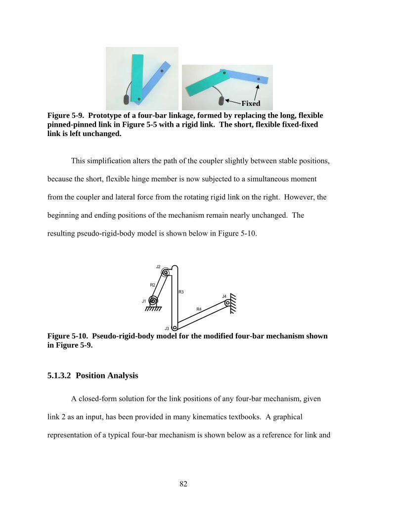
82
Figure 5-9. Prototype of a four-bar linkage, formed by replacing the long, flexible pinned-pinned link in Figure 5-5 with a rigid link. The short, flexible fixed-fixed link is left unchanged.
This simplification alters the path of the coupler slightly between stable positions,
because the short, flexible hinge member is now subjected to a simultaneous moment
from the coupler and lateral force from the rotating rigid link on the right. However, the
beginning and ending positions of the mechanism remain nearly unchanged. The
resulting pseudo-rigid-body model is shown below in Figure 5-10.
Figure 5-10. Pseudo-rigid-body model for the modified four-bar mechanism shown in Figure 5-9.
5.1.3.2 Position Analysis
A closed-form solution for the link positions of any four-bar mechanism, given
link 2 as an input, has been provided in many kinematics textbooks. A graphical
representation of a typical four-bar mechanism is shown below as a reference for link and
Fixed

83
joint nomenclature. The variables r1 through r4 and θ1 through θ4 are the primary
variables of interest.
Figure 5-11. Four-bar nomenclature typically used for positional analysis, from [8].
Relying on the condition that a closed vector loop is formed by all links in the
linkage, the same closed form solution can be derived for our case in which link 3 is the
input. The author takes the same approach as [45], yielding the closure equations:
⎥⎦
⎤⎢⎣
⎡−+−+
= −
334411
33441112 coscoscos
sinsinsintan
θθθθθθ
θrrrrrr (4)
and
)(tan2 14 t−=θ (5)
where
ACACBBt
−+−+−
=222σ
(6)

84
given
343141 cos2cos2 θθ rrrrA −= (7) 343141 sin2sin2 θθ rrrrB −= (8)
)sinsincos(cos2 3131312
22
42
32
1 θθθθ +−−++= rrrrrrC (9)
and where σ = ±1 is a sign change variable (negative in this case) that corresponds to the
assembly mode. For any input, θ3, the two possible values that result for θ2 and θ4 (based
on the sign of σ) correspond to the two possible assembly modes. Since this mechanism
is a non-Grashoff (triple-rocker) mechanism, it is able to move from one mode to the
other without the links being disassembled.
5.1.4 Bistability
To determine where the stable positions occur, total energy of the system is
considered. Potential energy stored in the flexible links is represented in the model by
torsional springs placed at joints between the appropriate links. In this case, the only two
springs are located at joints 1 and 2, at each end of the short flexible member. (see Figure
5-10) Thus, the total potential energy of the system is described by
)(
21 2
222
11 ψψ kkV += (10)

85
where ki represents the torsional spring constant and ψi is the angular displacement from
the joint’s undeflected position.
An approximation for the spring constant can be calculated when bending is the
dominant loading for the flexible member. This assumption is accepted as valid for a
preliminary analysis, and the equation is given in [8] as:
lEIk ΘΚ= γ2
(11)
in which γ is again the characteristic radius factor, ΚΘ is a nondimensionalized stiffness
coefficient, E is the modulus of elasticity, I is the moment of inertia, and l is the length of
the flexible segment.
Both spring constants are identically calculated to be 2.29 in-lb/rad2 (0.259
Nm/rad2) for the mechanism at hand. This is based on the material properties of
polypropylene, γ=.85 and ΚΘ=2.62 as suggested in [8], and a flexible member 0.05 in
(0.0013 m) thick by 0.25 in (0.00634 m) wide and 1 in (.0254 m) long.
Stable positions for the mechanism occur at local minima of the system’s
potential energy curve. Since the coupler is the input link, the total system potential
energy was calculated using the angular displacement of the two torsional springs over
the full range of viable input angles of the coupler. For a mechanism like the prototype in
Figure 5-9, the two local minima were found to be 97 degrees apart, as shown in Figure
5-12. Here, V1 and V2 corresponds to the potential energy for Joints 1 and 2 (shown in
Figure 5-9), and the total system energy (darker line) is the summation of the two.

86
Potential Energy
0
1
2
3
4
5
-30 0 30 60 90 120
Coupler Rotation (deg)
V (i
n-lb
)
V1V2Total
Figure 5-12. Total system potential energy curve. Note the two troughs corresponding to stable positions at 0o and 97o.
It should be noted that the horizontal scale in Figure 5-12 represents the change in
angular position of the coupler using the first stable position as the reference point. If
exactly 90 degrees of rotation are desired, the link lengths can be adjusted and optimized
to obtain the target spread between stable positions while maximizing the depth of the
troughs on the energy curve. This results in a robust design by maximizing the
mechanism’s stability, or resistance to restoring forces.
5.1.5 Locking Characteristic
The mockup prototype in Figure 5-9 possesses a unique locking characteristic.
Once deployed, a force applied at the point shown in Figure 5-13 has no effect on
restoring the mechanism to its original position. This locking phenomenon occurs when
the path of the applied force passes through the four-bar linkage’s instant center.

87
Figure 5-13. Method for graphically finding the instant center of a four-bar mechanism.
An instant center (IC) is defined as a point common to two bodies in plane motion
which has the same instantaneous velocity relative to each body. [46] For the coupler
and ground links of a four-bar linkage, the IC is thus a point of zero velocity, and can be
thought of as the center about which the coupler is rotating in the plane (relative to
ground) at any given instant.
The IC for the coupler relative to ground is found graphically by extending
imaginary lines from the two side links, as shown in Figure 5-13. This can be done
mathematically by simultaneously solving the two equations for the lines that include the
endpoints of each side link. The IC is located at the point of intersection for these two
lines. Figure 5-13 illustrates this concept for the mockup prototype shown in Figure 5-9.
A free-body diagram of the coupler link shows that the only external force acting
on the body is the applied force, F. Two reaction forces occur at the two pin joint
connections with the side links. Since the pin joints cannot sustain a moment, the
reaction forces must act along the axes of the two side links, and therefore through the
instant center. Thus all forces on the coupler pass through the same point (the IC),
resulting in no net moment on the coupler. It follows that the coupler will not rotate,
regardless of the magnitude of the applied force.
Input Force

88
This has obvious beneficial consequences when the joint is used for deployable
wings. If we represent aerodynamic drag on the wing by an equivalent point force, we
can design the joint mechanism in such a way that the force on the wing passes through
the joint’s instant center. The wings would then be effectively locked in place during
flight without the aid of any additional mechanical means of locking. The extent to
which the applied force passes directly through the IC determines the extent to which
locking occurs. That is, small deviations in the path of the applied force result in small
moment arms, requiring a large force to rotate the mechanism out of its stable position.
As the linkage rotates, the IC moves accordingly and traces out a path like that
shown in Figure 5-14, called a centrode. [46] The only point of interest for our
application is the final IC location when the mechanism has reached its stable, fully
“deployed” position.
Placement of the IC relative to the wing can affect the robustness of the wing
design. If the IC lies on the wing itself, slight changes in external conditions or
manufacturing errors would cause the equivalent drag force to miss the mechanism’s IC.
Small deviations would only marginally lessen the locking effect, but the extent of any
larger deviations would determine the extent to which the locking characteristic is
lessened or eliminated. On the other hand, placing the IC some distance from the wing
(but still along the path of the equivalent drag force) results in less of a proportional
deviation relative to the total distance between the mechanism and the IC. So for a robust
design, the IC should be located as far as possible behind the wing, while still coinciding
with the path of the drag force.

89
IC Location
-2
-1
0
1
2
3
4
-5 -3 -1 1 3
X (inches)Y (i
nche
s)
(a)
IC Location
-5
0
5
10
15
20
25
30
-20 -10 0 10
X (inches)
Y (in
ches
)
(b)
Figure 5-14. Centrode traced out by the coupler’s IC as the linkage rotates, for (a) the original mechanism in Figure 5-9, and (b) when relative link lengths are modified to move the final IC.
The four-bar link lengths can be adjusted to place the IC at a desirable distance.
One intuitive rule of thumb is useful here. To place the IC farther from the joint, the two
sides must be closer to parallel. This is accomplished by making links 1 and 3 or 2 and 4
(or both) closer to the same length. Ultimately, for a parallelogram, the IC is located at
infinity.
For the mechanism at hand, there is a tradeoff between moving the IC further
from the joint and reducing the maximum stress experienced by the short, flexible link.
Final IC Four-bar Linkage
Final IC
Four-bar Linkage
0

90
As the four-bar becomes more square there is less clearance between joints 1 and 3 as
they pass by each other. Thus the maximum distance the IC can be from the mechanism
is limited by the need to keep stresses below the yield point for the material. The stress is
best estimated using FEA software, as the flexible member undergoes multiple
simultaneous load conditions as the linkage rotates.
Without using FEA, a rough check can be made by examining the energy curve
for the mechanism. The slope of the energy curve represents the instantaneous force
required for motion. Thus, a sharp spike in the energy curve at the point where joints 1
and 3 move past each other gives an indication that significant stress will develop in the
flexible member. In our case, the link lengths were modified to produce an IC over 25”
(0.635 m) away from the mechanism (Figure 5-14b), with an even smoother peak on the
potential energy curve than the original design. This preliminary indicator suggests that
the modified design will have an even lower stress concentration than the original,
indicating a viable design. A full FEA analysis would be recommended before building a
final prototype or production model.
It should be noted that as the link lengths are adjusted, the two stable positions
also migrate. Optimization of link lengths should involve constraining the spread
between troughs on the potential energy curve. We note that 90 degrees of coupler
rotation between stable positions may not be an absolute requirement for many
applications. Because many airplanes have slightly swept-back wings, any amount of
rotation between about 75-90 degrees may be acceptable—especially considering that
enough wingspan reduction may take place even if the wings aren’t completely parallel
with the fuselage in the stored configuration.

91
There are many optimization packages which can be employed. The objective
function is set to constrain the change in coupler input between potential energy troughs
for the system and to place the IC within a desired distance from a reference point on the
mechanism, while varying the link lengths. The author has found the solver feature in
spreadsheet applications like Microsoft Excel to be sufficient for this purpose.
5.1.6 Manufacturability
The ideal mechanism can be quickly and reliably manufactured. This is often a
key design objective for small UAVs produced for aerial surveillance applications. The
two pin joints in the final four-bar linkage can be simulated with small-length flexural
pivots, or a passive joint. Figure 5-15 shows how the four-bar mechanism can be cut out
of a single sheet of polypropylene plastic. This allows manufacturing techniques such as
injection molding or computer-aided milling to quickly form the joint in an automated
setting. A small-length flexural pivot is placed between the coupler and side link at right.
A passive joint is used between that same side link and ground.
Figure 5-15. Manufacturable configuration of the final compliant four-bar mechanism.
Because the mechanism is already under a load in the first stable position, it must
be manufactured in its relaxed state and subsequently moved into position. This is

92
facilitated by the passive joint just mentioned. After cutting out the mechanism, the end
of link 4 is inserted into the cavity just above it, and the contact between the two acts as a
pin joint in rotation. Figure 5-16 shows the mechanism in action, with a Plexiglas
rectangle glued to the coupler to represent a wing.
(a)
(b)
(c)
Figure 5-16. Prototype demonstration of the four-bar mechanism, (a) stored, (b) transitioning, and (c) deployed.
5.1.7 Summary
This example successfully used the design process outlined in Chapter 4 to
demonstrate identifying design considerations, modeling, and analyzing the example

93
design. A novel concept for a rotating joint using compliance was introduced, and a
means for ensuring bistability and using a locking characteristic was established.
Many benefits are attained vs conventional rigid-body joints. The mechanism is
bistable for ease of deployment and robust performance, can be cut out in one plane for
ease of manufacture, and includes an inherent locking characteristic, eliminating the need
for additional mechanisms to keep it deployed during flight. Wear and maintenance are
also minimized with the reduction of separate parts.
The bistability and locking action result from strain energy inherently stored in
the compliant members. There is little discussion for such locking mechanisms in the
literature, particularly as relates to compliant mechanisms. The approach presented can
be used to design other locking mechanisms based on kinematic linkages for other
applications.
Finally, it was demonstrated that such a mechanism could be designed for easy
manufacture. Small length flexural pivots and passive joints were used to overcome
challenges in allowing for a preload that must be introduced after manufacturing in an
unstressed state. By allowing the mechanism to be cut out within a plane, techniques
such as injection molding or computer-aided milling can be used to produce the
mechanism quickly and efficiently in an automated environment. Minimal assembly is
required to achieve the finished product.
5.2 Example: The IRIS
This second design example illustrates the process used to design a folding wing
for the Micro Air Vehicle (MAV) group at Brigham Young University (BYU). BYU has
designed a platform of small UAVs that includes its own autopilot, video camera, and

94
capability for real-time video streaming to a laptop ground station. The goal is for the
UAV technology to meet the demands of military, law enforcement, and other
surveillance markets. Portability is favorable for virtually all applications, and a folding
wing option would allow the UAVs to perform in previously infeasible areas.
5.2.1 Background
BYU’s most recent UAV, IRIS, was selected to demonstrate the concept
evaluation and selection process. IRIS is a tailless “flying wing” with no fuselage. It has
a 45 cm wingspan, of which a span of approximately 15 cm in the center is occupied by
electronic components, as shown in Figure 5-17, below.
Figure 5-17. IRIS, BYU’s 45 cm wingspan ‘flying wing’ UAV.
5.2.2 Customer Needs
The most important design factor was weight. The low Reynolds number
operating point and limited power supply of the small UAV meant that extra weight for
the airframe would decrease available weight for battery capacity and potentially negate
the benefits of a deployable wing. High aerodynamic efficiency was also desired to

95
maximize range. Ease of deployment and reliability were important characteristics, as
the product would be used by consumers without a high user skill level.
5.2.3 Needs and Specifications
These key customer needs were quantified to form functional specifications,
shown in Table 5-3, below. The original IRIS weighed about 200 g, and the airframe
itself comprised about ¼ of that weight. An ideal design would not increase the weight
of the wing. Wingspan reduction wasn’t as critical, but the wingspan needed to at least
be cut in half, and the design needed to either separate or be flat enough to make storage
with a laptop feasible. Lifespan was calculated to allow the user to fold and unfold the
plane at least twice every day for a period of five years.
Table 5-3. Functional specifications, derived by assigning quantifiable values to key customer needs.
Functional Specifications
Total Lift 200 grams
Max Total Weight 50 grams
Turning acceleration 3 g's Min Wingspan Reduction 50% Max Time to Unpack & Deploy 2 min
Min Number of Cycles to Failure 3,700

96
5.2.4 Evaluation and Selection
With weight as the prime consideration, and emphasis on aerodynamic efficiency
and reliability, the concepts were screened to select three good options. The concept
screening matrix is shown below:
Table 5-4. Screening Matrix. H=High, M=Medium, L=Low.
Win
gspa
n R
educ
tion
Asp
ect R
atio
R
educ
tion
Wei
ght S
ensi
tivity
E
ffec
t on
Aer
odyn
amic
s R
elia
bilit
y E
ase
of D
eplo
ymen
t M
anuf
actu
rabi
lity
Max
imum
Fle
xure
1. Folding M M M L L H M H2. Rotating H L L L H H M H3. Segmented Rolling H H L L M L L M
4. Continuous Rolling H H M M H H H H
5. In-plane Bending M M H H M M L H
6. Doubling-over L M L H L L M H7. Sliding L H H L M M H M8. Telescoping H M H H M M M H9. Tucking H L M L M L M M
Motion types that would result in wings with reduced lift or complete reversal of
aspect ratio (such as rotating) were screened out. Figure 5-18 shows the three selected
motion types: folding, segmented rolling, and continuous rolling.
Design Criteria
Motion Types

97
(a) (b) (c)
Figure 5-18. Top three concepts for final selection: (a) folding (front view), (b) segmented rolling, and (c) continuous rolling (front view).
Weightings were assigned to emphasize the design characteristics of most
interest, and each of the three concepts was ranked in a Concept Scoring Matrix (Table
5-5). Scores of 1-5 were assigned, with 5 indicating the greatest ability to achieve the
evaluated criterion. Non-differentiating criteria for which each concept performed
equally were left out, since they didn’t help rank designs.
Table 5-5. Concept Scoring Matrix, an objective method for determining which concept best meets the design requirements and constraints.
Design Criteria Wei
ghtin
g Fa
ctor
(1) F
oldi
ng
(2) S
egm
ente
d
R
ollin
g (3
) Con
tinuo
us
Rol
ling
Weight 0.25 4 5 3 Reliability 0.14 3 4 2 Wingspan Reduction
0.11 4 5 4
Aerodynamic Efficiency
0.15 4 4 2
Manufacturability 0.18 4 3 1 Ease of Deployment 0.12 4 2 5 Lifespan 0.05 3 3 4 Weighted Totals: 1.00 3.81 3.89 2.75
After calculating total scores, the segmented rolling concept was selected. The
folding design received lower scores due to the anticipated additional locking mechanism

98
needed to hold the wing open for flight, and the continuous bending wing would have
been far more difficult to manufacture. The segmented rolling concept demonstrated
greater reliability with its built-in locking system, it could use existing materials, and it
added virtually no weight to the existing wing structure.
Figure 5-19. CAD model of the top layer for the segmented rolling wing concept selected.
5.2.5 Analysis
As a final step for showing the concept’s viability in this application, a basic
stress analysis was done to verify that the original polystyrene (EPS) would be a suitable
material for the prototype and to determine limits for the UAV’s performance. To
accommodate the layout of the original UAV, the prototype was modeled with a 15 cm
solid base in the center, and the wing ends were each divided into 15 1-cm wide
segments. The wing was then analyzed for failure in bending during flight by calculating
stresses where the lift distribution created the greatest moment.
5.2.5.1 Lift Distribution
According to Anderson [47], the lift distribution across the wing can be
approximated accurately by an elliptical curve given by:

99
2
021)(' ⎟
⎠⎞
⎜⎝⎛−Γ= ∞∞ b
yVyL ρ (12)
where Γ0 is given by
πρ bVL
∞∞
=Γ4
0
(13)
and the remaining variables are defined in Table 5-6.
Table 5-6. Definitions and values for variables used in calculating lift distribution. Variable Definition Value
∞ρ Air density 0.997 3mkg
∞V Velocity of the UAV 30 sm
y Coordinate along wing length (origin at center of wingspan)
Ranges from 2
b− to 2b
m b Wingspan 0.45 m L Total lift 1.962 N
By defining total lift as the weight of the completed UAV and plotting Equation
12 with the values given in Table 5-6, the resulting elliptical lift distribution for this UAV
is shown below in Figure 5-20.

100
Lift vs Wing Position
-2
0
2
4
6
-0.3 -0.2 -0.1 0 0.1 0.2 0.3
Wing position, y (m)
Lift
per U
nit A
rea,
L' (
N/m
)
Figure 5-20. Elliptical Lift Distribution for the BYU UAV.
5.2.5.2 Stress Analysis
Bending stress on the wing is greatest at its root, where the sum of the applied
moments is greatest. Kevlar fabric was used as the compliant surface on which 1 cm
wide polystyrene foam segments were attached with epoxy. Since Kevlar fabric has a
very high ultimate tensile strength, the wing would most likely fail in bending due to
compression at the top of the wing surface, and failure would occur at the foam segment
nearest the wing root (see Figure 5-21). For analysis, only the top wing layer was
considered; the bottom layer was neglected since it bends upward and wouldn’t provide
support against the wing’s lift.
Figure 5-21. Free Body Diagram for the UAV, with weight concentrated in the center and lift distributed.

101
Figure 5-22 shows a free-body diagram for the root segment and the base of the
wing containing most of the UAV’s weighty equipment. The maximum stress produced
in the segment is found from [48] by
IMc
=maxσ (14)
where M is the moment, c is the average thickness of the top wing layer, and I is the
moment of inertia of the wing cross-section. Note that the fabric acts as the effective
neutral axis. The foam blocks fail entirely due to compression, as the slits between them
prevent them from sustaining a tensile load.
Figure 5-22. Moment created by weight vs lift. The rigid body model depicts the connection of the root segment to the “fuselage” base as a pin joint.
The total moment on the root segment is added to by the collective moments from
each of the segments further down the wing. For simplicity, the effect of the cumulative
moments for all the segments along the wing length can be modeled as a point force
acting through the centroid of the elliptical lift area. The free body diagram is shown in
Figure 5-23.

102
Figure 5-23. The lift is modeled as a concentrated force acting through the centroid of the elliptical lift area, at a distance yc from the solid wing base.
To solve for the resulting moment exerted on the root segment, we first determine
the coordinate through which this concentrated force acts, and then determine the force
by integrating Equation 12 across the flexible wing portion. The centroid is found by:
∫∫=
dA
ydAyc
(15)
where
dy
byVdyLdA
2
021' ⎟
⎠⎞
⎜⎝⎛−Γ== ∞∞ρ
(16)
as illustrated in Figure 5-24 below.

103
Figure 5-24. Finding yc, the centroid of an elliptic section.
Performing the integral in Equation 15 between the limits of 0.075 m and 0.225 m
(corresponding to the flexible portion of the wing), we find that yc = 0.137 m. This gives
a moment arm of 0.062 m from the solid wing base of y = 0.075 m.
The total lift on the flexible segment, found by integrating Equation 12 between
the same limits, is Lflex = 0.573 N. This yields a total moment on the root segment of
0.355 Nm.
Using this moment, the maximum stress experienced by the root was found using
Eq. 3 to be 29.3 kPa. With a safety factor of 1.25, this becomes 36.6 kPa, one third of the
110 kPa compressive yield strength of EPS. Without reducing this safety factor, this
UAV will handle a 3.01 g turning acceleration, since the stress is proportional to the force
creating the moment on the root segment.
5.2.5.3 Prototype Verification
A proof of concept prototype is shown in Figure 5-25. A load was applied
upward at the wingtips equivalent to the weight, and the wing deflection was compared to
the original UAV under the same conditions. After firm contact between the segments,
the flexible wings deflected 0.23 m upward, compared with 0.17 m for the original UAV.
This 35% increase is due to the segments’ lower ability to resist vertical shear forces.
The deflection could likely be countered by building future prototypes with a slight

104
downward curvature of the wings while relaxed, so that the wing under stress becomes
straight or achieves the desired dihedral angle.
(a) (b)
(c)
Figure 5-25. Top layer prototype (a) laid flat, (b) with one wing rolled under, and (c) with both wings rolled under.
5.2.6 Results
This design demonstrated a successful application of the procedure outlined in
Chapter 4. The concept selection procedure was used to find an appropriate motion type
by exploring the classes of motion types. Concepts were then evaluated based on the key
design criteria. Concept screening and selection matrices demonstrated an objective
method for selecting the most fitting concept based on the key design criteria for BYU’s
MAV group. The segmented rolling motion type was selected for the IRIS due to its low
inherent weight, good propensity for lift, and manufacturability.
Testing should still be conducted to verify the basic analysis performed, and to
explore locking mechanisms for holding the wing in the in-flight configuration. Still, the

105
proof of concept prototype demonstrated a wing that fits the application, is easily
manufactured, accommodates the current electronic layout, and yields a robust design
capable of either folding over or completely rolling up, depending on the storage space
dimensions.

106

107
Chapter 6 Conclusions
The thesis has met the objectives set forth in the introductory chapter. A
classification system was developed for compliant, deployable wing concepts, as well as
a method and guidelines for evaluating folding wing designs for a given application. In
the process, a pool of concepts was generated to serve as a basis for stimulating future
concept ideas. The approach to developing compliant designs for certain applications
was illustrated through two example designs which were then modeled and analyzed to
demonstrate viability.
6.1 Conclusions
A process was introduced for developing deployable wings for SUAVs using
compliance, and this process was illustrated in the design of two example mechanisms,
demonstrating the viability of using compliant mechanisms to achieve the same functions
that rigid-body mechanisms typically perform. It was also shown that designers should
be careful to address key design considerations, such as motion duty cycle, actuation
methods, locking mechanisms, and manufacturability in addition to wingspan or volume
reduction. Off-axis stiffnes is also an important design characteristic to consider for
compliant mechanisms, as they inherently lack some rigidity in certain directions for their
compliant members. By defining design objectives early in the process, designers can

108
prioritize which considerations will require the most attention and give extra weight to
them during the screening and selection of potential wing motion concepts.
A number of potential concepts were generated and classified according to their
primary motion type. Linear, planar, and spatial motions were subdivided into sliding,
telescoping, rolling, bending, rotating, twisting, and crumpling subclasses. Example
concepts were demonstrated for each class, either with sketches or proof of concept
prototypes. Differing levels of energy storage plays into each of the motion types, and
must be considered as part of the design process. In most cases, it is optimal to select
mechanisms which provide both structural support or motion and energy storage for
actuation/stability. Mechanisms with inherent bistability are of particular interest since
they contribute to actuation as well as retaining the mechanism in a stable, low-energy
position so as to minimize creep in either of the stable configurations.
Design examples demonstrated the utility of the process for selecting relevant
concepts to the application. Modeling of the compliant rotating locking joint
demonstrated an unanticipated locking effect which the designer can exploit to match a
set of conditions by manipulating the placement of the mechanism’s instant center. The
joint achieved similar performance to rigid-body rotating joints, with the added benefits
of bistability and the ability to cut it out within the plane. The joint’s center also moves
during deployment, allowing the wing to both rotate and translate to accommodate the
opposite wing. The second example design, the segmented, rolling wing, showed the
concept selection process in more detail and demonstrated how novel ideas could be
generated for a less conventional airframe. Preliminary analysis and testing verified that

109
the deployable wing design would perform the required functions that the original wing
had.
6.2 Recommendations for Future Work
The research resulted in further topics of interest that could be explored by future
researchers. At present, the concept classification system was limited to possible motion
types for the wings. Other factors, such as energy storage, actuation, and locking
mechanisms were mentioned, but only as secondary considerations once a motion type
had been selected.
6.2.1 Energy Storage and Actuation
Further research on classifying energy storage and actuation methods would be
very useful. Many means of actuating deployment were suggested, but an organized
approach to choosing a method strategically would aid in design. Integrating this with
the current classification system for motion types would result in a much simpler design
process and eliminate some of the iteration.
6.2.2 Locking Mechanisms
The role of various locking mechanisms should also be explored. Whenever
energy storage is present—whether internal to the mechanism or external—some method
of locking the wing in its stored and in-flight configurations is necessary. This research
identified the benefit of achieving this function as an inherent characteristic of the
mechanism itself, but it would be useful to define how these characteristics relate to the

110
mechanism’s stored energy. Relationships to the means of actuating deployment should
also be identified.
6.2.3 Off-axis Stiffness
The flexible members that make compliant mechanisms so valuable becomes a
challenge when significant loads are present in secondary directions. Most compliant
mechanisms are very effective when motion and loads occur in one or two degrees of
freedom. However, in practice loads usually occur in multiple, unanticipated directions.
For wings, this usually results in flutter due to a lack of torsional stiffness.
Some research by Allen Mackey has addressed metrics for evaluating stiffness in
directions other than the desired direction of travel. These could be used as a basis for
developing new mechanism concepts that achieve large displacements but provide
rigidity in non-travel directions.
6.2.4 Additional Validation
Finally, building additional prototypes and validating concepts would prove very
useful. With development of new designs comes additional insight into unanticipated
challenges and a refinement of current concepts. Identification of optimal manufacturing
techniques or materials would help make the use of these mechanisms more widespread.
Such work would also generate new concepts that could be added to the current concept
pool and help to refine the concept classification system.
111
Appendix: Actuation Methods
Shape memory alloys, often Ni-Ti alloys, retain their permanent shape after being
heat treated. Subsequent heating (below the annealing temperature) causes the material
to return quickly to this memory shape—even after bends that stretch the material up to
8% of its original length, or 3% for infinite life. This means of actuation has been used
for novelty items with very light wings, and could be used to open folded or bent thin
profile sections of a UAV wing.
Inflatable wings have demonstrated that pressure can be an effective means of
deploying UAV wings of at least 5-6 ft wingspan. The pressurizing vessel may be
located onboard the UAV or separate from it—in which case a user could remove the
UAV from its storage container, add pressure to the wings, and launch it.
Chemical actuation is also feasible, as noted with the epoxy coated inflatable
wings that hardened under UV radiation. [30] Memory plastics are another option.
These were originally used to make lightweight, high-performance wire for aircraft (with
thinner insulation coatings) and have also been used for toys like Mattel’s Strange
Change Time Capsule Creatures, which unfold from small blocks of plastic into
dinosaurs, cavemen, etc. Deployable wings could be made for one-time deployment, or
could be heated and compressed for multiple deployments. The plastic is originally
molded in the deployed shape, and then subjected to a high-energy beam of electrons to
cross-link the polymer chains in formation. The chains become more like a stretchy net

112
than the usual “bowl of spaghetti noodles,” and are not able to slide by each other unless
heated to soften the material slightly. It is first dipped into silicon to keep from sticking
together, heated, compressed into a compact shape, and cooled. The cooled plastic is too
hard to spring back to the original shape until heat is re-introduced. The process is
reversible many times before the cross-linked bonds of the polymer net begin to wear out.
New memory plastics have been built to respond to specific wavelength bands of
UV light. [49] An example of the material behavior is shown in Figure A-1, below.
Using long wavelength UV light, the polymer cross-links into a temporary state, after
which it can be released to its original state by irradiating with short wavelength light to
cleave the initial covalent cross-linking bonds. With such a plastic, the UAV could be
removed from storage, subjected to the correct UV light to deploy in its natural
configuration, and then subjected to another wavelength light to return to its compact
storage configuration.
Figure A-1. A sample light-activated memory plastic, from [50].

113
References
[1] B. S. R. Gourley, "Tiny Eyes," in Special Operations Technology Online Archives. vol. 2, 2004.
[2] C. Farivar, "An Aerial Crime-Fighting Tool Banks on Portability," in The New York Times NY, 2005.
[3] P. Bowes, "High Hopes for Drone in L.A. Skies," in BBC News, 2006.
[4] S. Heal, "Discussion of SUAV Use and Technology," Personal Communication, 2005.
[5] J. W. Ramsey, "UAVs: Out of Uniform," in Aviation Today, 2004.
[6] L. Dickerson, "UAV Market to Top $13 Billion by 2014," Forecast International 21 October, 2005 2005.
[7] R. Kroyer, "Wing Mechanism Analysis," in Computers and Structures: Proceedings of the 12th ADINA Conference Cambridge, MA, 1999.
[8] L. L. Howell, Compliant Mechanisms: Wiley-IEEE, 2001.
[9] A. Scott, "Folding Feathered Wings," April 2007, http://www.windchaser.co.uk/art/tut_wings.html.
[10] F. M. Osborne, "Airplane," USPTO-Office, Ed., 1921.
[11] T. McDaniel, "Flying Machine," USPTO-Office, Ed., 1933.
[12] T. E. Doll, B. R. Jackson, and W. A. Riley, Navy Air Colors. Carrollton, TX: Squadron/Signal Publications, 1985.
[13] P. Mitchell, "Scuba Diving: M2 Submarine," 2007, http://www.submerged.co.uk/m2.php.
[14] W. Lee and R. Lee, "Aichi Seiran," April 2001, http://www.nasm.si.edu/research/aero/aircraft/aichi_serian.htm and www.j-models.org/seiran.htm.
[15] N. Walker, "Toy Glider," USPTO-Office, Ed., 1940.

114
[16] J. Pike, "A-3 / EA-3B Skywarrior," April 2004, http://www.globalsecurity.org/intell/systems/ea-3.htm.
[17] J. Anderson, "The Crosbie Folding Wing," December 1998, http://freespace.virgin.net/shadow.owners/anderson.htm.
[18] Mustang-Aeronautics, "Folding Wing," April 2007, http://www.mustangaero.com/Mustang%20II/FoldingWing.html.
[19] Aeromaster-Innovations, "Synergy - Roadable Aircraft - Hydraulic Folding Wings," Crafting Solutions dot com, 2006, http://www.dual-use.com/hydraulic_folding_wing.html.
[20] E. B. Online, "Tactical Guided Missiles: Guided-missile Systems: Air-to-surface," 2006.
[21] US-Army, "TOW Missile System," A. F. File, Ed., April 2007, http://www.army.mil/fact_files_site/tow/index.html.
[22] S. Kessler, S. Spearing, and G. Kirkos, "Design of a High-g Unmanned Aerial Vehicle Structure," in 2000 World Aviation Conference San Diego, CA, 2000.
[23] U. S. Navy, "Sonobuoy Tube-launched UAV," STTR, Ed., 2004.
[24] M. Ware, "UAVs in an Australian Maritime Environment," 2003, http://www.aeromech.usyd.edu.au/design/AERO4490/docs/2003_files/Tiny%20Tiger%20Sydney%20Uni%20Presentation.pdf.
[25] MAGGIC-Lab(BYU), "Photos: General Gallery," July 2004, http://www.et.byu.edu/groups/magicc/cmsmadesimple/uploads/images/archive/web_gallery1/index.html.
[26] P. G. Ifju, D. A. Jenkins, S. Ettinger, Y. Lian, and W. Shyy, "Flexible-Wing-Based Micro Air Vehicles," in AIAA, 2002.
[27] W. A. Sebrell, "Inflatable Wing," USPTO-Office, Ed., 1976.
[28] G. Brown, R. Haggard, and B. Norton, "Inflatable Structures for Deployable Wings," in AIAA Boston, MA, 2001.
[29] NASA, "Inflatable Wing Flights Prove Concept," Dryden Flight Research Center, Edwards, CA 9 July, 2001 2001.
[30] P. L. Barry, "Instant Glider--Just Add Light," 2003, http://science.nasa.gov/headlines/y2003/02may_bigblue.htm.
[31] F. S. Eastman, "The Design of Flexure Pivots," Journal of the Aeronautical Sciences, vol. 5, p. 6, 1937.

115
[32] A. Kyusojin and D. Sagawa, "Development of Linear and Rotary Movement Mechanism by Using Flexible Strips," Bulletin of Japan Society of Precision Engineering, vol. 22, p. 6, 4 December, 1988 1988.
[33] N. Lobontiu, Compliant Mechanisms: design of flexure hinges. Boca Raton, FL: CRC Press, 2003.
[34] L. L. Howell and A. Midha, "A Method for the Design of Compliant Mechanisms with Small-Length Flexural Pivots," ASME Journal of Mechanical Design, vol. 116, p. 10, 1994.
[35] J. A. Haringx, "The Cross-Spring Pivot as a Construction Element," Applied Scientific Research, vol. A, p. 20, 1949.
[36] S. T. Smith, Flexures: Elements of Elastic Mechanisms. Amsterdam, The Netherlands: Gordon and Breach Science Publishers, 2000.
[37] B. Jensen and L. L. Howell, "The Modeling of Cross-axis Flexural Pivots," Mechanism and Machine Theory, p. 16, 2002.
[38] M. Goldfarb and J. E. Speich, "Split Tube Flexure," USPTO-Office, Ed. USA, 2003.
[39] Y. M. Moon, B. P. Trease, and S. Kota, "Design of Large-Displacement Compliant Joints," in ASME 2002 Design Engineering Technical Conference, 27th Biennial Mechanisms and Robotic Conference Montreal, Canada, 2002.
[40] S. D. Landon, S. P. Magleby, and L. L. Howell, "Preliminary Concepts for Deployable wings on Small UAVs Using Compliance," in ASME 2005 International Mechanical Engineering Congress and Exposition Orlando, FL: ASME, 2005.
[41] D. W. Carroll, "Metamorphic Process for Compliant Ortho-planar Mechanism Design," in Mechanical Engineering. vol. MS Provo, UT: Brigham Young University, 2002.
[42] K. Ulrich and S. Eppinger, Product Design and Development, 2nd ed. Boston: McGraw-Hill, 2000.
[43] A. E. Guerinot, S. P. Magleby, L. L. Howell, and R. H. Todd, "Compliant Joint Design Principles for High Compressive Load Situations," Journal of Mechanical Design, 2004.
[44] B. Jensen and L. L. Howell, "Bistable configurations of Compliant Mechanisms Modeled Using Four Links and Translational Joints," Journal of Mechanical Design, vol. 126, p. 10, 2004.
116
[45] K. Waldron and G. Kinzel, Kinematics, Dynamics, and Design of Machinery. New York: Wiley, 1999.
[46] R. Norton, Design of Machinery, 2nd ed. Boston: McGraw-Hill, 1999.
[47] J. D. Anderson-Jr., Fundamentals of Aerodynamics, 3rd ed. New York: McGraw-Hill, 2001.
[48] J. M. Gere and S. P. Timoshenko, Mechanics of Materials. Boston, MA: PWS Publishing Company, 1997.
[49] A. Lendlein, H. Jiang, O. Juenger, and R. Langer, "Light-induced Shape-memory Polymers," Nature, vol. 434, p. 4, 14 April, 2005 2005.
[50] E. A. Thompson, "Intelligent Plastics Change Shape with Light," in Tech Talk: Serving the MIT Community. vol. 49, 2005.