development of catalysts for natural gas-fired gas turbine ...11407/fulltext01.pdf · development...
TRANSCRIPT
Development of catalysts for natural gas-fired gas turbine combustors
Sara Eriksson
Doctoral Thesis 2006
Department of Chemical Engineering and Technology
School of Chemical Science and Engineering KTH – Royal Institute of Technology
Stockholm, Sweden

TRITA-KET R232 ISSN 1104-3466 ISRN KTH/KET/R--232--SE ISBN 91-7178-543-4 ISBN 978-91-7178-543-5

To my family

Abstract Due to continuously stricter regulations regarding emissions from power generation processes, further development of existing gas turbine combustors is essential. A promising alternative to conventional flame combustion in gas turbines is catalytic combustion, which can result in ultralow emission levels of NOx, CO and unburned hydrocarbons. The work presented in this thesis concerns the development of methane oxidation catalysts for gas turbine combustors. The application of catalytic combustion to different combustor concepts is addressed in particular. The first part of the thesis (Paper I) reports on catalyst development for fuel-lean methane combustion. Supported Pd-based catalysts were investigated at atmospheric pressure. The effect on catalytic activity of diluting the reaction mixture with water and/or carbon dioxide was studied in order to simulate a combustion process with exhaust gas recirculation. The catalytic activity was found to decrease significantly in the presence of water and CO2. However, modifying the catalyst by changing support material can have a considerable impact on the performance. In the second part of this thesis (Papers II-IV), the development of rhodium catalysts for fuel-rich methane combustion is addressed. The effect of catalyst composition, oxygen-to-fuel ratio and catalyst pre-treatment on the methane conversion and the product gas composition was studied. An experimental investigation at elevated pressures of partial oxidation of methane/oxygen mixtures in exhaust gas-rich environments was also conducted. The most suitable catalyst identified for fuel-rich catalytic combustion of methane, i.e. Rh/Ce-ZrO2, showed benefits such as low light-off temperature, high activity and enhanced hydrogen selectivity. In the final part of the thesis (Paper V), a numerical investigation of fuel-rich catalytic combustion is presented. Measurements and predictions were compared for partial oxidation of methane in exhaust gas diluted mixtures at elevated pressures. The numerical model was validated for several Rh-based catalysts. The key parameter controlling the catalytic performance was found to be the noble metal dispersion. Keywords: AZEP, catalytic combustion, CPO, methane oxidation, palladium, rhodium, support effect
Sammanfattning
Eftersom utsläppskraven för energiproducerande anläggningar kontinuerligt skärps krävs utveckling av dagens förbränningsteknik. Katalytisk förbränning är ett attraktivt alternativ till konventionell flamförbränning då utsläppsnivåerna av NOx, CO och oförbrända kolväten kan minskas avsevärt. Arbetet som presenteras i denna avhandling behandlar utveckling av katalysatorer för förbränning av metan. Tillämpningen av katalytisk förbränning i olika förbränningskoncept för gasturbiner har särskilt undersökts. Första delen av avhandlingen (artikel I) behandlar katalysatorutveckling för förbränning av metan i luftöverskott. Palladiumkatalysatorer studerades vid atmosfäriskt tryck. Inverkan på metanomsättningen av att späda ut reaktionsblandningen med vatten och koldioxid undersöktes i syfte att simulera en förbränningsprocess med recirkulation av förbränningsprodukter. Den katalytiska aktiviteten minskade drastiskt i närvaro av vatten och koldioxid. Emellertid kan aktiviteten påverkas betydligt genom att använda olika bärarmaterial. Den andra delen av avhandlingen (artikel II-IV) rapporterar om utvecklingen av rodiumkatalysatorer för metanförbränning i bränsleöverskott. Effekten av katalysatorsammansättning, syre-till-bränsle förhållande samt förbehandling av katalysatorn undersöktes. En experimentell studie genomfördes vid höga tryck av partiell oxidation av CH4/O2 blandningar i närvaro av förbränningsprodukter. Den mest lämpliga katalysatorn för metanförbränning i bränsleöverskott (Rh/Ce-ZrO2) uppvisade egenskaper så som låg tändtemperatur, hög aktivitet och förbättrad selektivitet för vätgas. I den sista delen av avhandlingen (artikel V) har en numerisk analys av katalytisk förbränning i bränsleöverskott genomförts. En jämförelse mellan experimentella och numeriska resultat för partiell oxidation av metan i närvaro av förbränningsprodukter genomfördes. Den numeriska modellens giltighet kunde bekräftas för rodiumbaserade katalysatorer av olika sammansättning. Dispersionen av ädelmetall kunde identifieras som den mest betydelsefulla parametern för det katalytiska beteendet. Nyckelord: AZEP, CPO, effekt av bärarmaterial, katalytisk förbränning, oxidation av metan, palladium, rodium
Publications referred to in the thesis
The work presented in this thesis is based on the following publications, referred to in the text by their Roman numerals. The papers are appended at the end of the thesis. I. Catalytic combustion of methane in steam and carbon dioxide-diluted
reaction mixtures S. Eriksson, M. Boutonnet, and S. Järås, Appl. Catal. A 312 (2006) 95.
II. Partial oxidation of methane over rhodium catalysts for power generation
applications S. Eriksson, M. Nilsson, M. Boutonnet, and S. Järås, Catal. Today 100 (2005) 447.
III. Effect of Ce-doping on Rh/ZrO2 catalysts for partial oxidation of methane
S. Eriksson, S. Rojas, M. Boutonnet, and J.L.G. Fierro, submitted to Appl. Catal. A, 2006.
IV. Fuel-rich catalytic combustion of methane in zero emissions power
generation processes S. Eriksson, M. Wolf, A. Schneider, J. Mantzaras, F. Raimondi, M. Boutonnet, and S. Järås, Catal. Today 117 (2006) 447.
V. Experimental and numerical investigation of supported rhodium catalysts
for partial oxidation of methane in exhaust gas diluted reaction mixtures S. Eriksson, A. Schneider, J. Mantzaras, M. Wolf, and S. Järås, Manuscript.
Other publications 1. Microemulsion: an alternative route to preparing supported catalysts S. Rojas, S. Eriksson, and M. Boutonnet, in: J.J. Spivey (Ed.), Catal.
Special. Period. Rep. R. Soc. Chem. 17 (2004) 258. 2. Preparation of catalysts from microemulsions and their applications in
heterogeneous catalysis S. Eriksson, U. Nylén, S. Rojas, and M. Boutonnet, Appl. Catal. A 265
(2004) 207.
3. Catalytic combustion of methane over bimetallic catalysts A. Ersson, H. Kušar, S. Eriksson, M. Boutonnet, and S. Järås, presented at
the 5th International Workshop on Catalytic Combustion, Seoul, Korea, 2002.
4. Stability tests of catalysts for methane combustion
S. Eriksson, K. Persson, M. Boutonnet, and S. Järås, presented at the 10th Nordic Symposium on Catalysis, Helsingør, Denmark, 2002.
5. Catalytic combustion of methane in humid gas turbine cycles
K. Persson, S. Eriksson, P.O. Thevenin, and S.G. Järås, presented at the 10th Nordic Symposium on Catalysis, Helsingør, Denmark, 2002.
6. Stability tests of catalysts for methane combustion
S. Eriksson, K. Persson, M. Boutonnet, and S. Järås, presented at the 2nd EFCATS School on Catalysis, Tihany, Hungary, 2002.
7. Combustion of methane over ceria based catalysts
S. Eriksson, M. Boutonnet, and S. Järås, presented at the 6th EuropaCat, Innsbruck, Austria, 2003.
8. Partial oxidation of methane over rhodium catalysts for power generation
applications S. Eriksson, M. Nilsson, M. Boutonnet, and S. Järås, presented at the 11th Nordic Symposium on Catalysis, Oulu, Finland, 2004.
9. Effect of support material on the catalytic properties of bimetallic Pd-Pt catalysts for combustion of methane
K. Persson, S. Eriksson, M. Boutonnet, and S. Järås, presented at the 19th North American Meeting on Catalysis, Philadelphia, USA, 2005.
10. Fuel-rich catalytic combustion of methane in zero emission power
generation processes S. Eriksson, M. Wolf, A. Schneider, J. Mantzaras, F. Raimondi, M. Boutonnet, and S. Järås, presented at the 6th International Workshop on Catalytic Combustion, Isle of Ischia, Italy, 2005.
11. A study of supported rhodium catalysts for partial oxidation of methane
S. Eriksson, M. Boutonnet, and S. Järås, presented at the 12th Nordic Symposium on Catalysis, Trondheim, Norway, 2006.
Contributions to the papers
I. I am the main author of Paper I and I also performed the experimental
work.
II. I am the main author of Paper II. M. Nilsson performed most of the experimental work under my guidance.
III. I am the main author of Paper III. The experimental work was a joint
effort between S. Rojas, J.L.G. Fierro and myself.
IV. I am the main author of Paper IV. The experimental work was a joint effort between A. Schneider, F. Raimondi and myself.
V. Paper V was written by J. Mantzaras, A. Schneider and myself. Both
experimental and numerical work was performed jointly by A. Schneider and myself.
Contents
1 Introduction 1
1.1 The Advanced Zero Emission Power (AZEP) concept 2
1.2 Scope of the work 2
2 Gas Turbine Combustion 5
2.1 Gas turbine configuration 5
2.2 Emissions from combustion 5
2.3 Zero emission combustion concepts 8
2.3.1 Post-combustion capture 9
2.3.2 Oxy-fuel combustion 9
2.3.3 Pre-combustion decarbonization 11
3 Catalytic Combustion 13
3.1 Introduction 13
3.2 The combustion catalyst 14
3.3 Reaction mechanism and operating conditions 17
3.4 Catalytic combustor design 19
3.4.1 Fully catalytic design 19
3.4.2 Hybrid design 19
3.5 Commercial status of catalytic combustors 20
4 Experimental Set-Up 23
4.1 Atmospheric lab-scale reactor 23
4.2 High-pressure subscale gas turbine reactor 24
5 Catalyst Development 27
5.1 Introduction 27
5.2 Fuel-lean catalytic combustion over Pd (Paper I) 28
5.2.1 Structure sensitivity 29
5.2.2 Stability of PdO 30
5.2.3 Influence of combustion products 32
5.3 Fuel-rich catalytic combustion over Rh (Papers II-IV) 35
5.3.1 Influence of support material (Papers II and III) 36
5.3.2 Nature of active Rh sites (Paper III) 38
5.3.3 Catalytic combustion in AZEP mixtures (Paper IV) 40
5.3.4 Reaction mechanism (Papers III and IV) 44
6 Numerical Investigation of Catalytic Combustion (Paper V) 47
6.1 Introduction 47
6.2 Numerical model 48
6.3 Catalytic partial oxidation in AZEP mixtures 52
7 Conclusions 55
Acknowledgements 59
Nomenclature 61
References 63
Appendices: Papers I-V
Chapter 1
Introduction Gas turbines that burn fuel to generate heat are widely used for the production of electricity. Natural gas is commonly used as fuel for stationary gas turbines due to low levels of impurities and long-term availability. However, the combustion process produces emissions that are harmful for the environment, i.e. oxides of nitrogen (NOx), unburned hydrocarbons (UHC), carbon monoxide (CO) and soot. The effect of these emissions was noticed in the 1950s when phenomena such as smog and acid rain were identified. This awareness resulted in strict regulations regarding emissions of pollutants being issued. Today, the control of emissions is one of the most important factors to consider when designing a gas turbine. Catalytic combustion is an attractive alternative to conventional flame combustion from an environmental point of view. The main advantages of this technology are the opportunity to perform the combustion reaction over a wide range of fuel-to-air ratios and the ability to operate at lower temperatures than for conventional flame combustion. These features provide the possibility to reduce emission levels of pollutants such as NOx, CO, UHC and soot considerably. Since the concept of catalytically stabilized combustion was introduced in the 1970s, extensive research on finding suitable catalyst materials has been conducted.
1
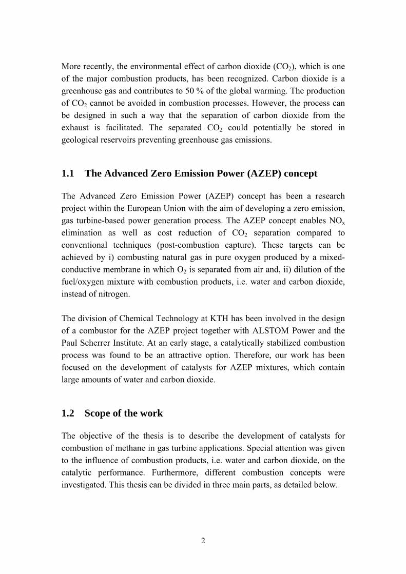
More recently, the environmental effect of carbon dioxide (CO2), which is one of the major combustion products, has been recognized. Carbon dioxide is a greenhouse gas and contributes to 50 % of the global warming. The production of CO2 cannot be avoided in combustion processes. However, the process can be designed in such a way that the separation of carbon dioxide from the exhaust is facilitated. The separated CO2 could potentially be stored in geological reservoirs preventing greenhouse gas emissions.
1.1 The Advanced Zero Emission Power (AZEP) concept
The Advanced Zero Emission Power (AZEP) concept has been a research project within the European Union with the aim of developing a zero emission, gas turbine-based power generation process. The AZEP concept enables NOx elimination as well as cost reduction of CO2 separation compared to conventional techniques (post-combustion capture). These targets can be achieved by i) combusting natural gas in pure oxygen produced by a mixed-conductive membrane in which O2 is separated from air and, ii) dilution of the fuel/oxygen mixture with combustion products, i.e. water and carbon dioxide, instead of nitrogen. The division of Chemical Technology at KTH has been involved in the design of a combustor for the AZEP project together with ALSTOM Power and the Paul Scherrer Institute. At an early stage, a catalytically stabilized combustion process was found to be an attractive option. Therefore, our work has been focused on the development of catalysts for AZEP mixtures, which contain large amounts of water and carbon dioxide.
1.2 Scope of the work
The objective of the thesis is to describe the development of catalysts for combustion of methane in gas turbine applications. Special attention was given to the influence of combustion products, i.e. water and carbon dioxide, on the catalytic performance. Furthermore, different combustion concepts were investigated. This thesis can be divided in three main parts, as detailed below.
2
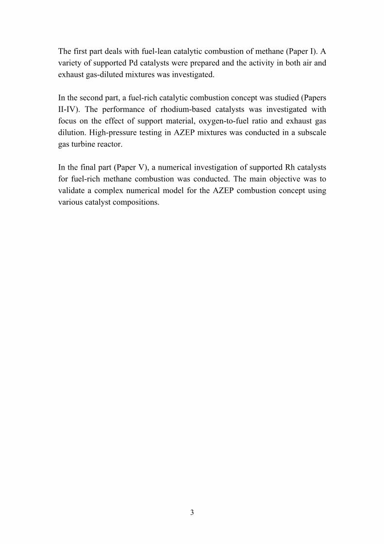
The first part deals with fuel-lean catalytic combustion of methane (Paper I). A variety of supported Pd catalysts were prepared and the activity in both air and exhaust gas-diluted mixtures was investigated. In the second part, a fuel-rich catalytic combustion concept was studied (Papers II-IV). The performance of rhodium-based catalysts was investigated with focus on the effect of support material, oxygen-to-fuel ratio and exhaust gas dilution. High-pressure testing in AZEP mixtures was conducted in a subscale gas turbine reactor. In the final part (Paper V), a numerical investigation of supported Rh catalysts for fuel-rich methane combustion was conducted. The main objective was to validate a complex numerical model for the AZEP combustion concept using various catalyst compositions.
3

4
Chapter 2
Gas Turbine Combustion
2.1 Gas turbine configuration
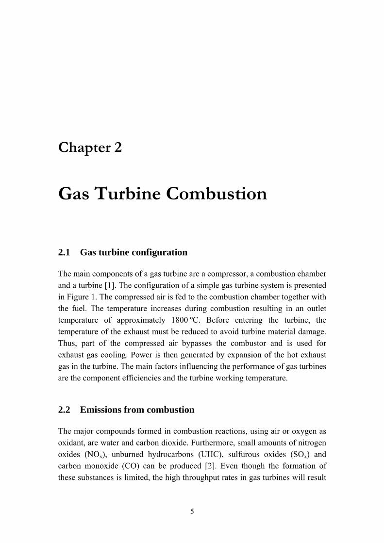
The main components of a gas turbine are a compressor, a combustion chamber and a turbine [1]. The configuration of a simple gas turbine system is presented in Figure 1. The compressed air is fed to the combustion chamber together with the fuel. The temperature increases during combustion resulting in an outlet temperature of approximately 1800 ºC. Before entering the turbine, the temperature of the exhaust must be reduced to avoid turbine material damage. Thus, part of the compressed air bypasses the combustor and is used for exhaust gas cooling. Power is then generated by expansion of the hot exhaust gas in the turbine. The main factors influencing the performance of gas turbines are the component efficiencies and the turbine working temperature.
2.2 Emissions from combustion
The major compounds formed in combustion reactions, using air or oxygen as oxidant, are water and carbon dioxide. Furthermore, small amounts of nitrogen oxides (NOx), unburned hydrocarbons (UHC), sulfurous oxides (SOx) and carbon monoxide (CO) can be produced [2]. Even though the formation of these substances is limited, the high throughput rates in gas turbines will result
5
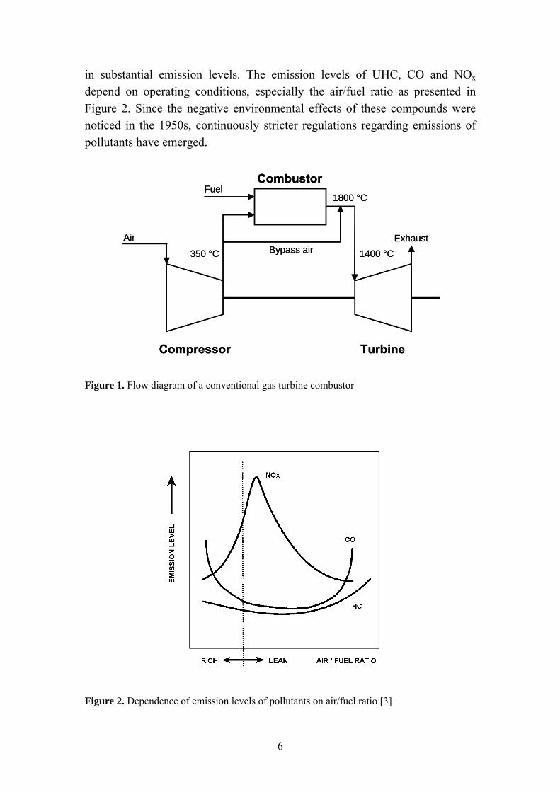
in substantial emission levels. The emission levels of UHC, CO and NOx depend on operating conditions, especially the air/fuel ratio as presented in Figure 2. Since the negative environmental effects of these compounds were noticed in the 1950s, continuously stricter regulations regarding emissions of pollutants have emerged.
Air
FuelCombustor
Compressor Turbine
ExhaustBypass air350 °C
1800 °C
1400 °C
Air
FuelCombustor
Compressor Turbine
ExhaustBypass air350 °C
1800 °C
1400 °C
Figure 1. Flow diagram of a conventional gas turbine combustor
Figure 2. Dependence of emission levels of pollutants on air/fuel ratio [3]
6
When the combustion process is incomplete, only partial oxidation of the fuel occurs resulting in the formation of UHC and CO. The formation of CO is favored by low amounts of H2 in the fuel, rapid exhaust gas cooling rates and short residence times. CO can also be produced at high flame temperatures where CO2 dissociation occurs. The main environmental concern regarding carbon monoxide is related to human health since it is highly toxic and can cause suffocation. The formation of UHC emissions is controlled by the same factors as CO and, therefore, they tend to follow the same trends. Sulfurous oxides (SOx) may be formed when combusting a sulfur-containing fuel. This is generally the case for fuels such as heavy oils and coal. However, gaseous fuels such as natural gas contain very small amounts of sulfur. The main sulfurous oxide formed under combustion conditions is SO2. The primary environmental effects of SOx emissions include acid rain and human suffocation at sufficient concentrations. The minimization of NOx emissions is at present one of the major concerns of gas turbine combustion. Environmental effects such as ozone depletion, acid rain and smog formation have been identified. Nitrogen oxides include nitric oxide (NO) and nitrogen dioxide (NO2) with NO being the predominant form in combustion emissions. Nitric oxide can be produced according to three different mechanisms: fuel, prompt and thermal. Fuel NOx is produced by oxidation of fuel-bound nitrogen whereas prompt NOx is formed by high-speed reactions of nitrogen, oxygen and hydrocarbon radicals. Prompt NOx is usually formed in combustion chambers operating with hydrocarbon fuel-rich flames. Thermal NOx is formed by oxidation of atmospheric nitrogen and is generally the main mechanism above 1100 ºC. The formation rate of thermal NOx has been found to increase exponentially with temperature making a reduction of the flame temperature the key factor for achieving low NOx emissions. For gas turbine systems, this means that a decrease of the adiabatic flame temperature is required. Emissions of nitrogen oxides can be drastically reduced by water injection, exhaust gas cleanup by selective catalytic reduction (SCR) or dry low NOx technologies. The injection of water, or steam, results in a decrease of the flame temperature and, therefore, lower levels of NOx emissions. In dry low NOx technologies, combustor designs resulting in a lower flame temperature are
7
used. A common approach is to use a lean premixed combustor. However, this can cause problems such as poor combustion efficiency and flame instability resulting in higher emission levels of CO and UHC. An example of dry low NOx technologies is catalytic combustion, which allows a stable combustion reaction to take place at significantly lower temperatures than for conventional flame combustion. Therefore, ultralow levels of NOx emissions (< 3 ppm) can be achieved while keeping the formation of UHC and CO low.
2.3 Zero emission combustion concepts
More recently, the environmental effect of carbon dioxide has been noticed. Although some controversy exists, most agree that emissions of CO2 are connected to global warming. The high CO2 levels present today are related to both fossil fuel combustion and forest depletion. The production of CO2 cannot be avoided for combustion processes since it is a main reaction product. However, the process can be modified in order to facilitate the separation of carbon dioxide from the exhaust. The captured CO2 can potentially be stored in oceans or geological reservoirs, i.e. depleted oil and gas reservoirs or deep saline aquifers. Another alternative is to use carbon dioxide for enhanced oil recovery, which is already occurring today. To facilitate the reduction of greenhouse gases, the Kyoto Protocol was adopted in 1997 [4]. The aim of the protocol is to prevent dangerous anthropogenic interference with the climate system and it contains legally binding emission targets for developed countries for the post-2000 period. A total reduction of greenhouse gas emissions from 1990 levels by 5 % over the period 2008-2012 should be achieved. Within the European Community, an emission trade system for CO2, according to the Kyoto Protocol, started in February 2005. Technologies for carbon dioxide capture from fossil fuel combustion processes can be divided into the following main groups [5]:
• Post-combustion capture • Oxy-fuel combustion • Pre-combustion decarbonization
8
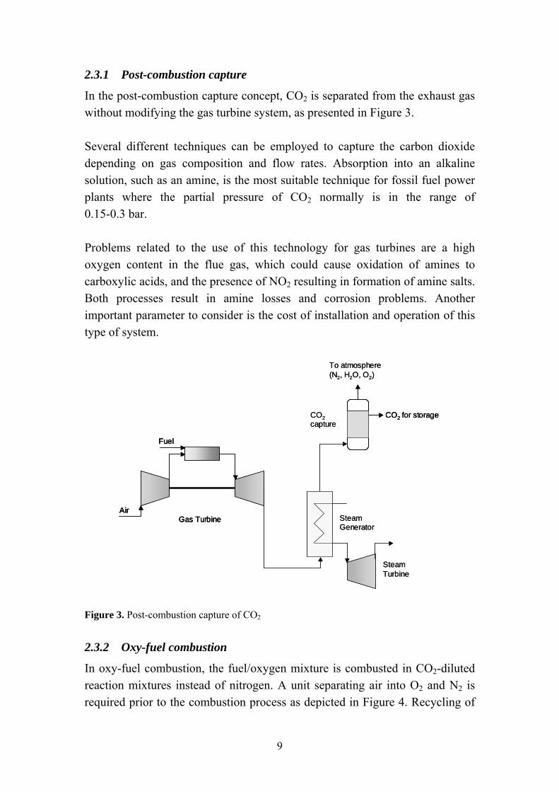
2.3.1 Post-combustion capture
In the post-combustion capture concept, CO2 is separated from the exhaust gas without modifying the gas turbine system, as presented in Figure 3. Several different techniques can be employed to capture the carbon dioxide depending on gas composition and flow rates. Absorption into an alkaline solution, such as an amine, is the most suitable technique for fossil fuel power plants where the partial pressure of CO2 normally is in the range of 0.15-0.3 bar. Problems related to the use of this technology for gas turbines are a high oxygen content in the flue gas, which could cause oxidation of amines to carboxylic acids, and the presence of NO2 resulting in formation of amine salts. Both processes result in amine losses and corrosion problems. Another important parameter to consider is the cost of installation and operation of this type of system.
Air
Fuel
Gas Turbine Steam Generator
Steam Turbine
CO2 for storage
To atmosphere(N2, H2O, O2)
CO2capture
Air
Fuel
Gas TurbineAir
Fuel
Gas Turbine Steam Generator
Steam Turbine
CO2 for storageCO2 for storage
To atmosphere(N2, H2O, O2)
CO2capture
Figure 3. Post-combustion capture of CO2
2.3.2 Oxy-fuel combustion
In oxy-fuel combustion, the fuel/oxygen mixture is combusted in CO2-diluted reaction mixtures instead of nitrogen. A unit separating air into O2 and N2 is required prior to the combustion process as depicted in Figure 4. Recycling of
9
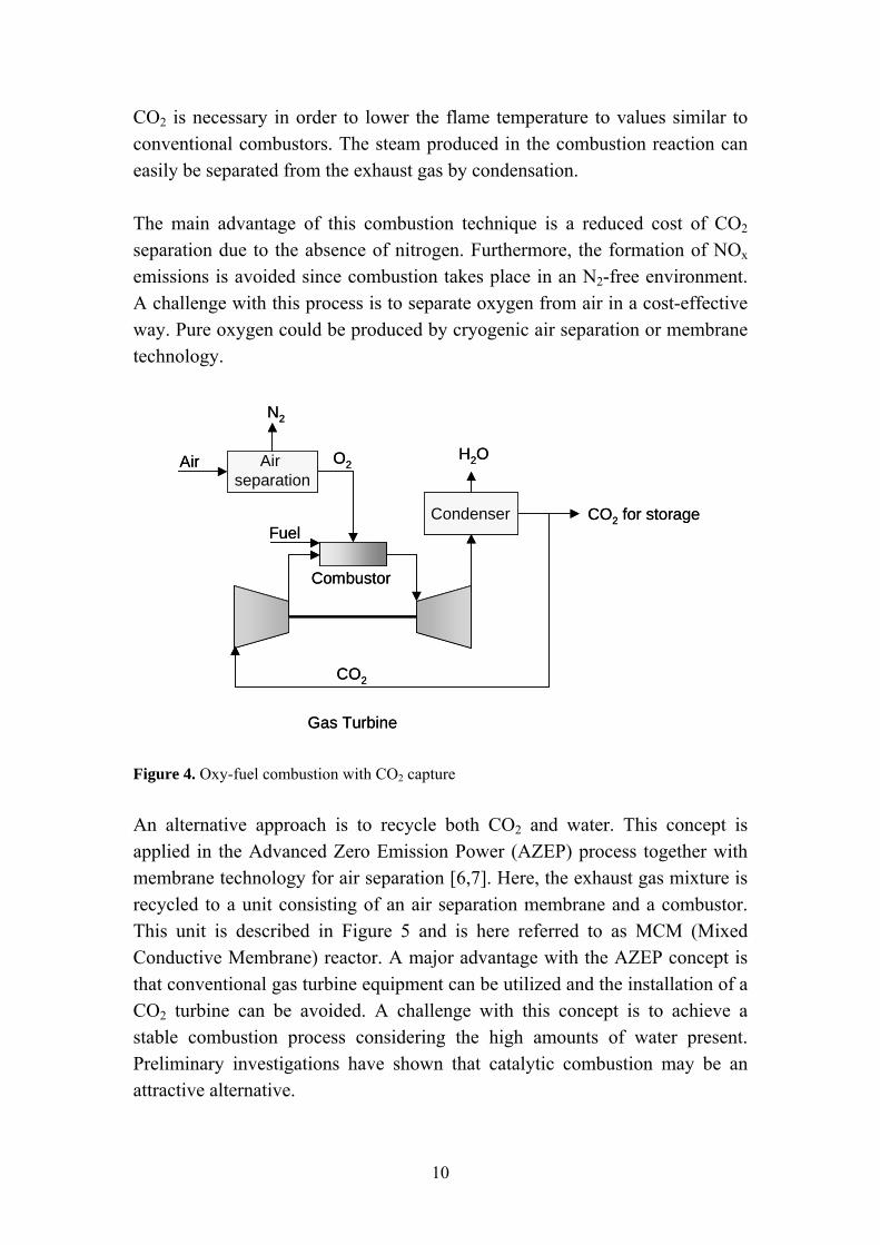
CO2 is necessary in order to lower the flame temperature to values similar to conventional combustors. The steam produced in the combustion reaction can easily be separated from the exhaust gas by condensation. The main advantage of this combustion technique is a reduced cost of CO2 separation due to the absence of nitrogen. Furthermore, the formation of NOx emissions is avoided since combustion takes place in an N2-free environment. A challenge with this process is to separate oxygen from air in a cost-effective way. Pure oxygen could be produced by cryogenic air separation or membrane technology.
Air
Fuel
Gas Turbine
Air separation
N2
O2
CO2
Condenser
H2O
CO2 for storage
Combustor
Air
Fuel
Gas Turbine
Air separation
Air separation
N2
O2
CO2
Condenser
H2O
CO2 for storage
Combustor
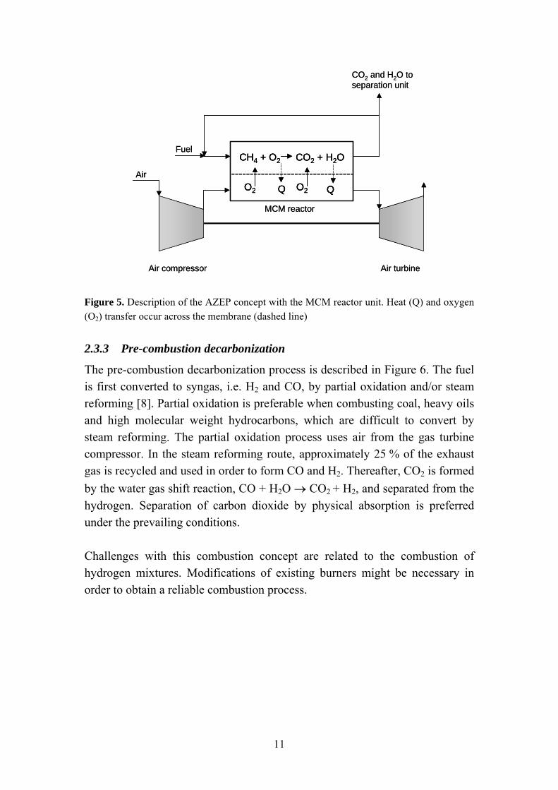
Figure 4. Oxy-fuel combustion with CO2 capture An alternative approach is to recycle both CO2 and water. This concept is applied in the Advanced Zero Emission Power (AZEP) process together with membrane technology for air separation [6,7]. Here, the exhaust gas mixture is recycled to a unit consisting of an air separation membrane and a combustor. This unit is described in Figure 5 and is here referred to as MCM (Mixed Conductive Membrane) reactor. A major advantage with the AZEP concept is that conventional gas turbine equipment can be utilized and the installation of a CO2 turbine can be avoided. A challenge with this concept is to achieve a stable combustion process considering the high amounts of water present. Preliminary investigations have shown that catalytic combustion may be an attractive alternative.
10
Air
Fuel
Air compressor
CH4 + O2 CO2 + H2O
O2 O2Q Q---------------------------------
Air turbine
CO2 and H2O to separation unit
MCM reactor
Air
Fuel
Air compressor
CH4 + O2 CO2 + H2O
O2 O2Q Q
CH4 + O2 CO2 + H2O
O2 O2Q Q---------------------------------
Air turbine
CO2 and H2O to separation unit
MCM reactor
Figure 5. Description of the AZEP concept with the MCM reactor unit. Heat (Q) and oxygen (O2) transfer occur across the membrane (dashed line)
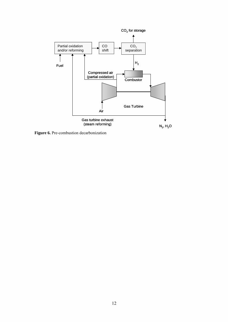
2.3.3 Pre-combustion decarbonization
The pre-combustion decarbonization process is described in Figure 6. The fuel is first converted to syngas, i.e. H2 and CO, by partial oxidation and/or steam reforming [8]. Partial oxidation is preferable when combusting coal, heavy oils and high molecular weight hydrocarbons, which are difficult to convert by steam reforming. The partial oxidation process uses air from the gas turbine compressor. In the steam reforming route, approximately 25 % of the exhaust gas is recycled and used in order to form CO and H2. Thereafter, CO2 is formed by the water gas shift reaction, CO + H2O → CO2 + H2, and separated from the hydrogen. Separation of carbon dioxide by physical absorption is preferred under the prevailing conditions. Challenges with this combustion concept are related to the combustion of hydrogen mixtures. Modifications of existing burners might be necessary in order to obtain a reliable combustion process.
11
AirGas Turbine
H2
Combustor
N2, H2O
Fuel
CO2separation
CO2 for storage
COshift
Partial oxidation and/or reforming
Gas turbine exhaust(steam reforming)
Compressed air(partial oxidation)
AirGas Turbine
H2
Combustor
N2, H2O
Fuel
CO2separation
CO2 for storage
COshift
Partial oxidation and/or reforming
Gas turbine exhaust(steam reforming)
Compressed air(partial oxidation)
Figure 6. Pre-combustion decarbonization
12
Chapter 3
Catalytic Combustion
3.1 Introduction
Catalytic combustion can be divided into primary and secondary combustion processes. In primary processes, the objective is to produce heat while limiting the amount of pollution formation. Secondary processes typically deal with abatement of volatile organic compounds (VOC). Secondary processes are also called low-temperature catalytic combustion since they occur at temperatures below 400 ºC. In primary processes, higher concentrations of hydrocarbons are present in the feedstream. Thus, considerably higher temperatures (> 1000 ºC) can be achieved. Only catalytic combustion for gas turbine applications, which obviously is a primary process, will be discussed here. Catalytic combustion for gas turbines is a promising alternative to conventional flame combustion that has been extensively investigated for more than 30 years [9,10]. This technique utilizes a catalyst, which is placed in the combustion chamber as presented in Figure 7. The fuel is oxidized at the catalyst surface without requiring a flame. Since complete combustion can occur outside the flammability limits of the fuel/oxygen mixture, lower combustor outlet temperatures are achieved and the need for bypass air cooling can be avoided [11].
13
Air
Fuel
Catalyticcombustor
Compressor Turbine
Exhaust350 °C
<1400 °C
Air
Fuel
Catalyticcombustor
Compressor Turbine
Exhaust350 °C
<1400 °C
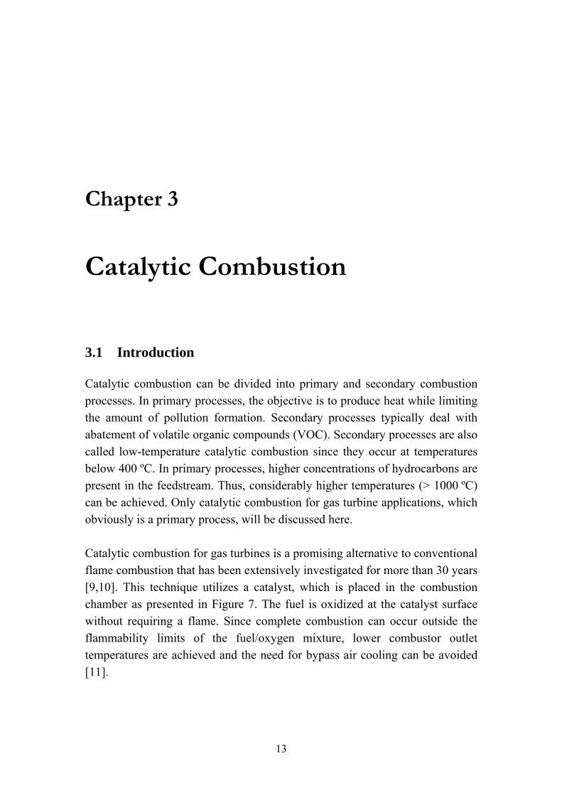
Figure 7. Flow diagram of a catalytic gas turbine combustor The main advantages of this technique are the opportunity to perform the combustion reaction over a wide range of fuel-to-air ratios and the ability to operate at lower temperatures than possible for conventional flame combustion. Thus, emission levels of pollutants such as NOx, CO, soot and unburned hydrocarbons can be reduced significantly. Catalytic combustion also reduces the risk of blow-out or instabilities occurring during operation. Natural gas is the most widely considered fuel for catalytic gas turbines. The composition of natural gas varies somewhat depending on source location but the main constituent is methane. In addition, small amounts of higher hydrocarbons such as ethane, propane and butane are present. Alternative fuels for catalytic gas turbines could be diesel or gasified biomass.
3.2 The combustion catalyst
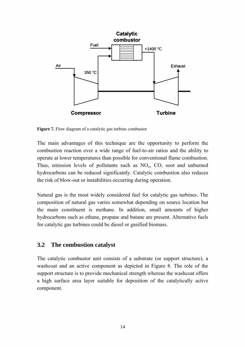
The catalytic combustor unit consists of a substrate (or support structure), a washcoat and an active component as depicted in Figure 8. The role of the support structure is to provide mechanical strength whereas the washcoat offers a high surface area layer suitable for deposition of the catalytically active component.
14
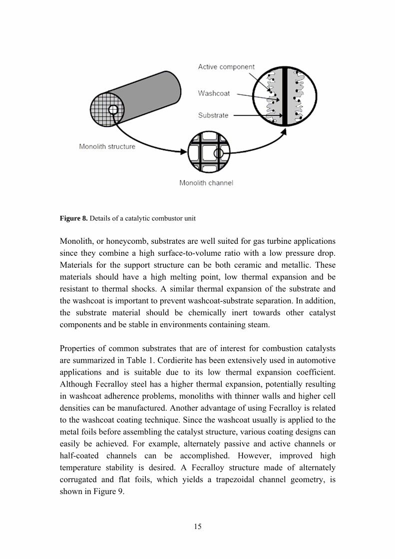
Figure 8. Details of a catalytic combustor unit Monolith, or honeycomb, substrates are well suited for gas turbine applications since they combine a high surface-to-volume ratio with a low pressure drop. Materials for the support structure can be both ceramic and metallic. These materials should have a high melting point, low thermal expansion and be resistant to thermal shocks. A similar thermal expansion of the substrate and the washcoat is important to prevent washcoat-substrate separation. In addition, the substrate material should be chemically inert towards other catalyst components and be stable in environments containing steam. Properties of common substrates that are of interest for combustion catalysts are summarized in Table 1. Cordierite has been extensively used in automotive applications and is suitable due to its low thermal expansion coefficient. Although Fecralloy steel has a higher thermal expansion, potentially resulting in washcoat adherence problems, monoliths with thinner walls and higher cell densities can be manufactured. Another advantage of using Fecralloy is related to the washcoat coating technique. Since the washcoat usually is applied to the metal foils before assembling the catalyst structure, various coating designs can easily be achieved. For example, alternately passive and active channels or half-coated channels can be accomplished. However, improved high temperature stability is desired. A Fecralloy structure made of alternately corrugated and flat foils, which yields a trapezoidal channel geometry, is shown in Figure 9.
15
Table 1. Properties of common support structures [12]. Material
Cordierite Fecralloy
Composition 2MgO⋅2Al2O3⋅5SiO2 15% Cr, 5% Al Y traces, balance Fe
Thermal expansion coefficient (10-6 cm/°C)
1 11
Maximum temperature (°C)
1200-1400 1250-1350
The role of the washcoat is primarily to provide a high surface area suitable for deposition of the active component. The material is typically a metal oxide of relatively high surface area such as Al2O3, ZrO2, SiO2 or mixed metal oxides. The thermal stability of the washcoat should be considered to avoid phase transitions during reaction that may cause encapsulation of the active component and, consequently, loss of activity. For example, γ-Al2O3 is a commonly used washcoat material with a high surface area (200 m2/g). However, thermal treatment above 1150 °C results in the formation of α-Al2O3, which is accompanied by a drastic decrease in surface area to ca. 5 m2/g [13]. Small amounts of stabilizers can be added to improve the thermal stability. In addition, washcoat properties such as acidity, crystal structure and support-noble metal interaction can influence the catalytic performance significantly.
Figure 9. Catalyst structure based on alternately flat and corrugated Fecralloy foils. Courtesy of ALSTOM Power
16
The active component should be well dispersed on the washcoat to maximize the number of active sites. Other aspects to consider related to the active phase include particle size and oxidation state. Suitable materials to use as active component in methane oxidation catalysts are discussed in Section 5.
3.3 Reaction mechanism and operating conditions
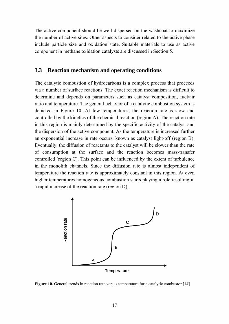
The catalytic combustion of hydrocarbons is a complex process that proceeds via a number of surface reactions. The exact reaction mechanism is difficult to determine and depends on parameters such as catalyst composition, fuel/air ratio and temperature. The general behavior of a catalytic combustion system is depicted in Figure 10. At low temperatures, the reaction rate is slow and controlled by the kinetics of the chemical reaction (region A). The reaction rate in this region is mainly determined by the specific activity of the catalyst and the dispersion of the active component. As the temperature is increased further an exponential increase in rate occurs, known as catalyst light-off (region B). Eventually, the diffusion of reactants to the catalyst will be slower than the rate of consumption at the surface and the reaction becomes mass-transfer controlled (region C). This point can be influenced by the extent of turbulence in the monolith channels. Since the diffusion rate is almost independent of temperature the reaction rate is approximately constant in this region. At even higher temperatures homogeneous combustion starts playing a role resulting in a rapid increase of the reaction rate (region D).
A
B
C
D
Rea
ctio
n ra
te
Temperature
A
B
C
D
Rea
ctio
n ra
te
Temperature Figure 10. General trends in reaction rate versus temperature for a catalytic combustor [14]
17
The severe conditions that combustion catalysts are exposed to for long periods of time place specific requirements on the choice of material and design of the combustor system. The most important design considerations for gas turbine catalytic combustors have been outlined by Carroni et al. [15] and are summarized below. • The catalyst must be thermally stable. Adiabatic flame temperatures of
up to 1500 °C are common for large gas turbines. An improved combustor design based on the hybrid concept (see Section 3.3) can lower the peak temperature in the catalyst. Still, catalysts of high thermal stability must be developed to avoid sintering, which may lead to agglomeration or vaporization of the active phase together with loss of porosity of the support structure.
• The mechanical integrity of the catalytic system should be maintained
despite the thermal shocks occurring when rapid changes in load take place.
• Catalysts of high activity are required for the light-off stage.
Compressor outlet temperatures of 350-450 °C are usually obtained for gas turbines operating at 50-100 % load. Hence, catalyst light-off temperatures in this range are desirable in order to avoid the need for pre-burners, which may generate NOx emissions.
• Pressures of 8 to 30 bar (50-100 % load) are typical for gas turbine
combustors. High pressures increase the risk for homogeneous ignition in the catalyst, which would cause catalyst destruction.
• To cope with the high mass flow rates used in gas turbines, a catalyst of
high surface area with minimal pressure losses (< 3%) must be provided. Catalytic structures of honeycomb type are utilized to minimize the pressure drop.
• A uniform mixing of fuel and air/oxygen should be obtained. A low
mixedness could cause catalyst overheating related to local adiabatic temperature variations. The problem with pressure losses associated with high levels of mixing must also be considered.
18
• The catalyst must be able to handle variations in fuel composition. Natural gas, which is the preferred fuel for gas turbines, contains mainly methane. However, small amounts of higher hydrocarbons of high reactivity increase the risk for homogeneous ignition in the catalyst. The catalyst must also be resistant to poisons such as sulfur.
• The gas turbine system must be reliable and operate for at least 8000 h
with changes in load. Furthermore, variations in ambient conditions (-25 to +40 °C) should not cause problems.
• The size of the catalytic combustor should be approximately the same as
those of conventional burners (typically 300 mm length and 180 mm diameter) to allow retrofitting of existing systems.
3.4 Catalytic combustor design
Ideally, a catalyst with both a high activity and long-term stability under all conditions relevant for gas turbine combustors, i.e. over a broad power load range, is preferred. In reality, it is a great challenge to obtain such a catalyst. Several combustor designs have been proposed in order to overcome these problems. Some of these configurations will be summarized here. More detailed information on this subject can be found elsewhere [12].
3.4.1 Fully catalytic design
In this design, all of the fuel and compressed air are mixed before entering the catalytic combustor. This configuration relies on a highly active ignition catalyst at the entrance and thermally stable catalysts further downstream. The catalytic end segment should be active to some extent but, most importantly, stable at temperatures up to 1300 ºC, which is very difficult to obtain.
3.4.2 Hybrid design
This two-stage combustion configuration consists of a catalytic segment followed by homogeneous gas phase combustion, i.e. flame combustion. Thus, a high temperature catalytic end segment can be avoided. The fuel is partly combusted over the catalyst, resulting in a moderate temperature increase, and complete conversion is obtained in the homogeneous zone. The catalyst outlet
19
temperature is generally below 1000 ºC. Several different designs resulting in partial conversion of the fuel have been proposed. A catalyst of monolith structure with alternately coated channels can be utilized to control the catalyst temperature. The heat generated by combustion in the active channels is transported by conduction through the walls to the inactive channels. The fuel/air mixture entering the inactive channels without catalyst coating is heated but will not be combusted before the high temperature homogeneous zone is reached. An advantage with this catalyst configuration is that the heat transfer to inactive channels prevents the formation of hot spots, which can damage the catalyst. If a fully coated catalyst structure is used, secondary fuel or secondary air configurations can be used to limit the catalyst temperature. In the secondary fuel configuration, part of the fuel is completely combusted over the catalyst and the remaining fuel is introduced directly to the subsequent homogeneous zone. In the secondary air concept, fuel-rich catalytic combustion occurs in the first stage producing hydrogen and carbon monoxide in addition to products of complete combustion. Additional air is added after the catalyst to fully oxidize the partial oxidation products, i.e. H2 and CO, in the homogeneous zone.
3.5 Commercial status of catalytic combustors
The first commercial catalytic combustor for natural gas-fired gas turbines was recently introduced. In 2002, the XONON cool combustion system, which utilizes a two-stage lean premix pre-burner configuration, was commercialized by Catalytica Energy Systems [16,17]. Since then, a 1.4 MW Kawasaki M1A-13X gas turbine equipped with a XONON combustor has been operating in California. The combustor has a guaranteed life of 8000 h with emission levels of NOx < 3 ppm and CO and UHC < 6 ppm. A metallic monolith with alternately coated channels is utilized to limit the maximum catalyst wall temperature. Development of hybrid catalytic combustors has been carried out by Siemens Westinghouse Power Corp. for large industrial engines (> 200 MW) and by Solar Turbines for smaller engines (< 20 MW) [18]. Other actors in this field are ALSTOM Power, General Electric, Allison Engines and CRIEPI.
20
However, further development of catalytic combustors is required to improve this technology and expand the field of application. The development of catalytic combustors has until now mainly been focused on fuel-lean methane combustion. This configuration usually requires a pre-burner in order to achieve low-temperature ignition, which results in higher levels of NOx emissions. Also, the flexibility of the combustor should be improved to meet variations in load, ambient conditions and gas turbine size. Moreover, other combustion concepts have emerged lately resulting in the need for different catalytic systems. The combustor concept utilizing secondary air resulting in fuel-rich catalytic combustion is one example. Benefits such as low-temperature ignition have been observed [19]. Therefore, pre-heaters could potentially be avoided. The development of catalytic materials for this concept together with testing under gas turbine conditions are of interest. Another example is the zero emission combustion concept utilizing exhaust gas recirculation as discussed previously.
21

22
Chapter 4
Experimental Set-Up Two different experimental facilities were used for catalyst testing. An atmospheric lab-scale reactor suitable mainly for catalyst material screening was available at KTH. This reactor system was designed for very dilute reaction mixtures enabling good temperature control of the catalyst. A high-pressure subscale gas turbine reactor at the Paul Scherrer Institute was used for testing under real AZEP conditions, i.e. feed mixtures of fuel/oxygen heavily diluted with water and CO2.
4.1 Atmospheric lab-scale reactor
The lab-scale reactor operating at atmospheric pressure consists of a quartz tube (16 mm inner diameter) placed in a cylindrical furnace as presented in Figure 11. Thermocouples (K-type) were inserted at the inlet and outlet of the catalyst as well as inside the furnace to monitor the temperature. Water could be introduced at the reactor inlet via a syringe pump connected to an evaporator. Reactants and products were analyzed by paramagnetic (O2), thermal conductivity (H2) and IR spectroscopy (CH4, CO, CO2) techniques. Water was removed from the exhaust gas by condensation prior to analysis.
23
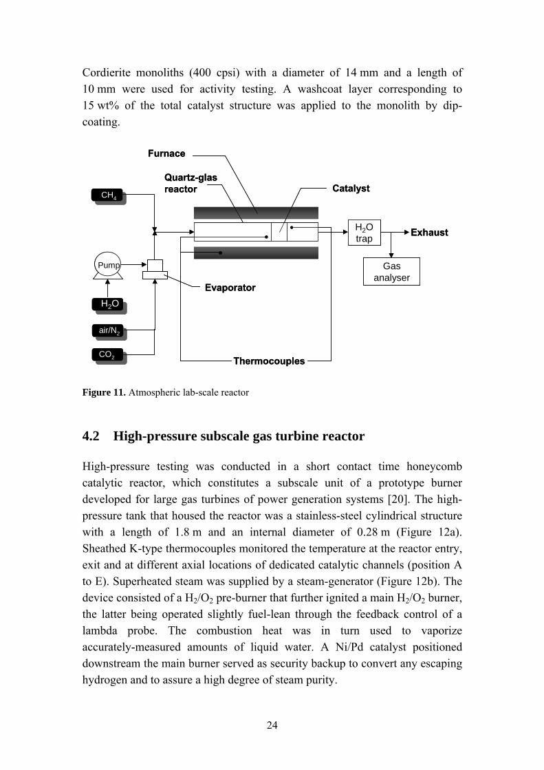
Cordierite monoliths (400 cpsi) with a diameter of 14 mm and a length of 10 mm were used for activity testing. A washcoat layer corresponding to 15 wt% of the total catalyst structure was applied to the monolith by dip-coating.
Exhaust
Pump Gas analyser
Evaporator
Furnace
Thermocouples
H2O trap
CH4
H2O
air/N2
CatalystQuartz-glas reactor
CO2
Exhaust
Pump Gas analyser
Evaporator
Furnace
Thermocouples
H2O trap
CH4
H2O
air/N2
CatalystQuartz-glas reactor
CO2 Figure 11. Atmospheric lab-scale reactor
4.2 High-pressure subscale gas turbine reactor
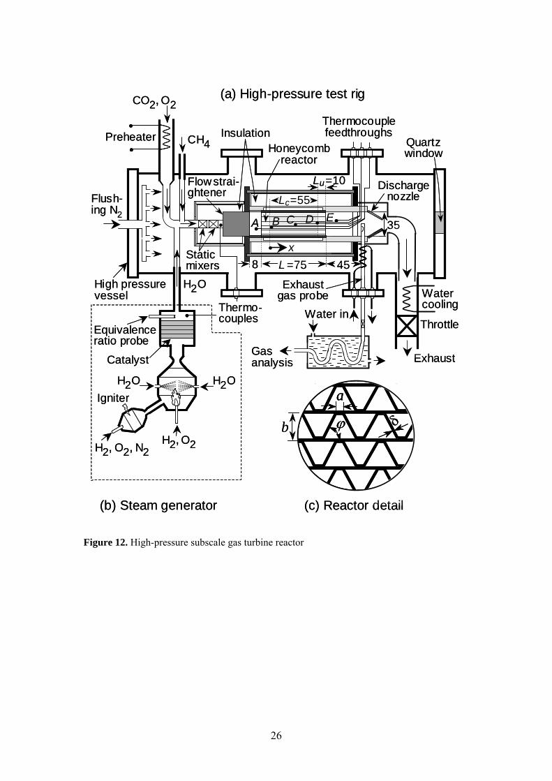
High-pressure testing was conducted in a short contact time honeycomb catalytic reactor, which constitutes a subscale unit of a prototype burner developed for large gas turbines of power generation systems [20]. The high-pressure tank that housed the reactor was a stainless-steel cylindrical structure with a length of 1.8 m and an internal diameter of 0.28 m (Figure 12a). Sheathed K-type thermocouples monitored the temperature at the reactor entry, exit and at different axial locations of dedicated catalytic channels (position A to E). Superheated steam was supplied by a steam-generator (Figure 12b). The device consisted of a H2/O2 pre-burner that further ignited a main H2/O2 burner, the latter being operated slightly fuel-lean through the feedback control of a lambda probe. The combustion heat was in turn used to vaporize accurately-measured amounts of liquid water. A Ni/Pd catalyst positioned downstream the main burner served as security backup to convert any escaping hydrogen and to assure a high degree of steam purity.
24
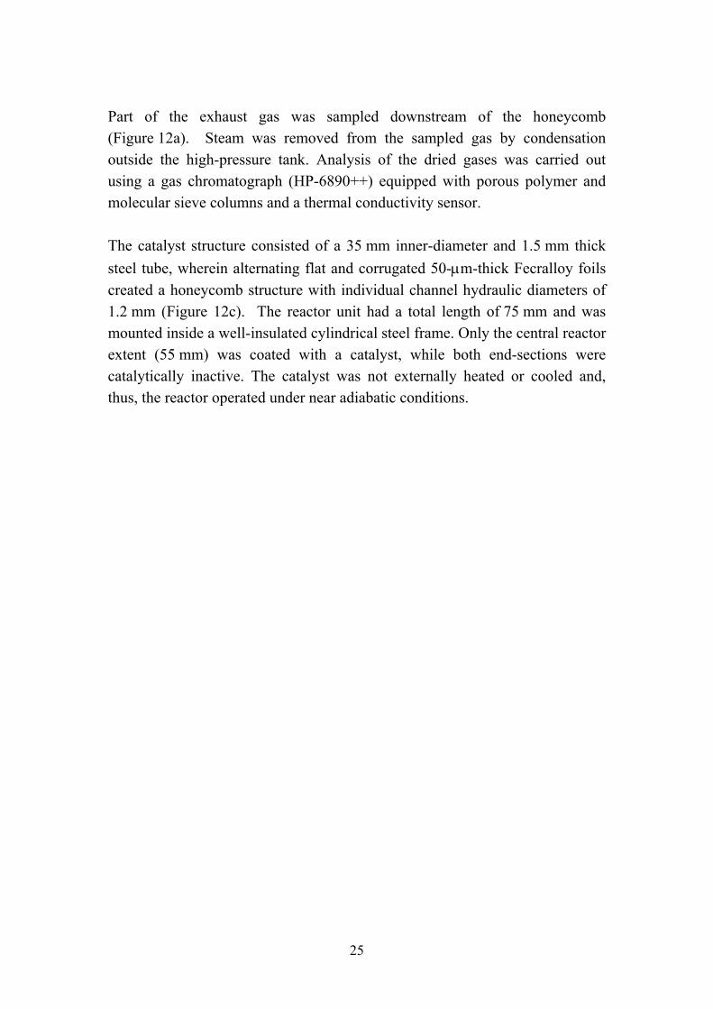
Part of the exhaust gas was sampled downstream of the honeycomb (Figure 12a). Steam was removed from the sampled gas by condensation outside the high-pressure tank. Analysis of the dried gases was carried out using a gas chromatograph (HP-6890++) equipped with porous polymer and molecular sieve columns and a thermal conductivity sensor. The catalyst structure consisted of a 35 mm inner-diameter and 1.5 mm thick steel tube, wherein alternating flat and corrugated 50-μm-thick Fecralloy foils created a honeycomb structure with individual channel hydraulic diameters of 1.2 mm (Figure 12c). The reactor unit had a total length of 75 mm and was mounted inside a well-insulated cylindrical steel frame. Only the central reactor extent (55 mm) was coated with a catalyst, while both end-sections were catalytically inactive. The catalyst was not externally heated or cooled and, thus, the reactor operated under near adiabatic conditions.
25
CO2, O2
CH4
Throttle
PreheaterThermocouplefeedthroughs
Staticmixers
Watercooling
High pressurevessel
(a) High-pressure test rig
H2, O2
H2O
H2, O2, N2
H2O
Equivalenceratio probe
Igniter
Catalyst
(b) Steam generator
Flush-ing N2
InsulationHoneycomb
reactor
L =758
Flowstrai-ghtener
Water in
Dischargenozzle
A
x
a
δϕb
Exhaust
(c) Reactor detail
Exhaustgas probe
45
B C D ELc=55
Thermo-couples
Gasanalysis
Lu=10
H2O
35
Quartzwindow
CO2, O2
CH4
Throttle
PreheaterThermocouplefeedthroughs
Staticmixers
Watercooling
High pressurevessel
(a) High-pressure test rig
H2, O2
H2O
H2, O2, N2
H2O
Equivalenceratio probe
Igniter
Catalyst
(b) Steam generator
Flush-ing N2
InsulationHoneycomb
reactor
L =758
Flowstrai-ghtener
Water in
Dischargenozzle
A
x
a
δϕb
a
δϕbb
Exhaust
(c) Reactor detail
Exhaustgas probe
45
B C D ELc=55
Thermo-couples
Gasanalysis
Lu=10
H2O
35
Quartzwindow
Figure 12. High-pressure subscale gas turbine reactor
26

Chapter 5
Catalyst Development
5.1 Introduction
The wide range of operating conditions that combustion catalysts are exposed to, with temperatures varying from 350 up to 1300 °C and pressures of 8-30 bar, implies that no single catalytic material alone could fulfill the requirements with respect to activity and thermal stability. Hence, a staged combustion system, constituting a highly active ignition catalyst at the inlet followed by one or more thermally stable catalyst(s) further downstream, would be a suitable solution. A combustor design based on the hybrid concept (see Section 3.4.2) is likely to be the most viable approach to development of catalytic gas turbine combustors. Since this design is based on only part of the fuel being oxidized over the catalyst, the catalyst surface will not be exposed to adiabatic temperatures. Thus, the need for a catalytic material operating at temperatures above 1000 °C can be avoided. The first catalytic stage should be highly active facilitating light-off at 350-450 °C. The most feasible option for achieving this is to use noble metals such as Pd, Pt, Rh and Au, which are known for their excellent ability to oxidize hydrocarbons. The choice of noble metal depends on fuel type and operating conditions. In addition, noble metals are less susceptible to sulfur poisoning than metal oxides. The catalyst used for the second stage can be less
27

active. Instead, emphasis should be on the thermal stability of the material. Metal oxides such as perovskites, doped metal oxides or hexaaluminates may be suitable candidates. Since meeting the light-off constraint has been shown to be a major obstacle when developing catalytic combustors focus here will be on catalytic materials for the first stage. Possible materials for high temperature catalysts have been reviewed by Zwinkels et al. [14]. Catalysts based on Pd and Pt have been widely studied for combustion applications due to their relatively low volatility and high specific activity. The use of noble metals for combustion of methane and lower alkanes has been reviewed by Choudhary et al. [21]. Palladium shows higher activity for oxidation of CO, methane and olefins whereas the activity for paraffin oxidation is higher for platinum [22]. The available literature on lower alkane combustion over Rh-based catalysts is rather limited [23]. However, catalysts containing rhodium have been extensively investigated for automotive applications and partial oxidation reactions [24-27]. In the following sections, results regarding catalyst development for both fuel-lean and fuel-rich combustion of methane are summarized. Issues related to combustion in AZEP mixtures, i.e. high amounts of water and CO2, were addressed in particular.
5.2 Fuel-lean catalytic combustion over Pd (Paper I)
Palladium catalysts have been widely investigated for methane oxidation in excess air with results showing a superior activity compared to other noble metals. Therefore, supported Pd catalysts were selected for studying methane combustion under fuel-lean conditions. Supported Pd catalysts, containing 5 wt% noble metal, were prepared by incipient wetness impregnation using a noble metal nitrate solution. The catalyst powders were applied to cordierite monoliths by dip-coating. Moreover, powder samples were characterized by X-ray diffraction (XRD), CO chemisorption and temperature-programmed oxidation (TPO).
28
5.2.1 Structure sensitivity
Whether the complete oxidation of methane over Pd-based catalysts is structure sensitive or not has been debated in the literature. A number of studies have reported strong variations in catalytic activity with varying dispersions, which implies that the reaction is structure sensitive [28-31]. Hicks et al. [30] measured the activity of supported Pd catalysts at 335 °C and reported turnover frequencies of 0.02 and 1.3 s-1 for small and large palladium particles, respectively. The structure sensitivity was related to differences in reactivity of adsorbed oxygen on the metal surface. On the contrary, Ribeiro et al. [31] concluded that complete oxidation of methane is structure insensitive over Pd supported on Al2O3 or ZrO2. The catalytic activity of supported Pd catalysts in air as a function of catalyst inlet temperature is presented in Figure 13. Significant variations in activity could be observed for the different catalyst compositions. The Pd/ZrO2 catalyst exhibited the highest low-temperature activity with light-off occurring at 348 ºC. Here, the light-off temperature is defined as the inlet temperature required for 10 % conversion of methane. Higher temperatures, 383 and 442 ºC, were required for light-off over Pd/Zr-CeO2 and Pd/La-CeO2, respectively. The differences in light-off temperature observed can be related to a variation of the PdO particle size for the catalysts. Particle sizes of 2.1, 2.4 and 8.5 nm were determined for Pd/La-CeO2, Pd/Zr-CeO2 and Pd/ZrO2, respectively. The results are thus in agreement with the reaction being structure sensitive with higher activity observed for larger Pd particles. However, the possibility of noble metal-support interactions affecting the activity cannot be excluded.
29
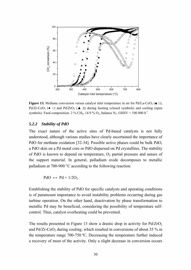
Figure 13. Methane conversion versus catalyst inlet temperature in air for Pd/La-CeO2 (■ □), Pd/Zr-CeO2 (● ○) and Pd/ZrO2 (▲ ∆) during heating (closed symbols) and cooling (open symbols). Feed composition: 2 % CH4, 14.9 % O2, balance N2. GHSV = 100 000 h-1
5.2.2 Stability of PdO
The exact nature of the active sites of Pd-based catalysts is not fully understood, although various studies have clearly ascertained the importance of PdO for methane oxidation [32-34]. Possible active phases could be bulk PdO, a PdO skin on a Pd metal core or PdO dispersed on Pd crystallites. The stability of PdO is known to depend on temperature, O2 partial pressure and nature of the support material. In general, palladium oxide decomposes to metallic palladium at 700-900 °C according to the following reaction:
PdO ↔ Pd + 1/2O2
Establishing the stability of PdO for specific catalysts and operating conditions is of paramount importance to avoid instability problems occurring during gas turbine operation. On the other hand, deactivation by phase transformation to metallic Pd may be beneficial, considering the possibility of temperature self-control. Thus, catalyst overheating could be prevented. The results presented in Figure 13 show a drastic drop in activity for Pd/ZrO2 and Pd/Zr-CeO2 during cooling, which resulted in conversions of about 35 % in the temperature range 700-750 ºC. Decreasing the temperature further induced a recovery of most of the activity. Only a slight decrease in conversion occurs
30
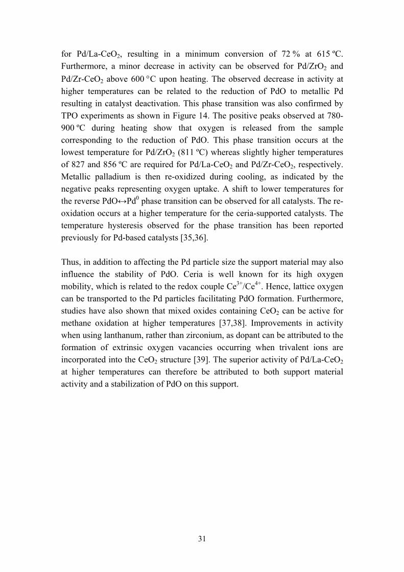
for Pd/La-CeO2, resulting in a minimum conversion of 72 % at 615 ºC. Furthermore, a minor decrease in activity can be observed for Pd/ZrO2 and Pd/Zr-CeO2 above 600 °C upon heating. The observed decrease in activity at higher temperatures can be related to the reduction of PdO to metallic Pd resulting in catalyst deactivation. This phase transition was also confirmed by TPO experiments as shown in Figure 14. The positive peaks observed at 780-900 ºC during heating show that oxygen is released from the sample corresponding to the reduction of PdO. This phase transition occurs at the lowest temperature for Pd/ZrO2 (811 ºC) whereas slightly higher temperatures of 827 and 856 ºC are required for Pd/La-CeO2 and Pd/Zr-CeO2, respectively. Metallic palladium is then re-oxidized during cooling, as indicated by the negative peaks representing oxygen uptake. A shift to lower temperatures for the reverse PdO↔Pd0 phase transition can be observed for all catalysts. The re-oxidation occurs at a higher temperature for the ceria-supported catalysts. The temperature hysteresis observed for the phase transition has been reported previously for Pd-based catalysts [35,36]. Thus, in addition to affecting the Pd particle size the support material may also influence the stability of PdO. Ceria is well known for its high oxygen mobility, which is related to the redox couple Ce3+/Ce4+. Hence, lattice oxygen can be transported to the Pd particles facilitating PdO formation. Furthermore, studies have also shown that mixed oxides containing CeO2 can be active for methane oxidation at higher temperatures [37,38]. Improvements in activity when using lanthanum, rather than zirconium, as dopant can be attributed to the formation of extrinsic oxygen vacancies occurring when trivalent ions are incorporated into the CeO2 structure [39]. The superior activity of Pd/La-CeO2 at higher temperatures can therefore be attributed to both support material activity and a stabilization of PdO on this support.
31
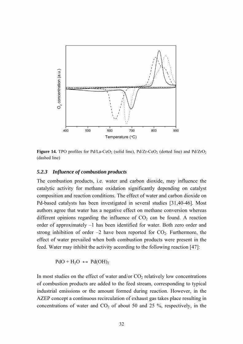
Figure 14. TPO profiles for Pd/La-CeO2 (solid line), Pd/Zr-CeO2 (dotted line) and Pd/ZrO2 (dashed line)
5.2.3 Influence of combustion products
The combustion products, i.e. water and carbon dioxide, may influence the catalytic activity for methane oxidation significantly depending on catalyst composition and reaction conditions. The effect of water and carbon dioxide on Pd-based catalysts has been investigated in several studies [31,40-46]. Most authors agree that water has a negative effect on methane conversion whereas different opinions regarding the influence of CO2 can be found. A reaction order of approximately –1 has been identified for water. Both zero order and strong inhibition of order –2 have been reported for CO2. Furthermore, the effect of water prevailed when both combustion products were present in the feed. Water may inhibit the activity according to the following reaction [47]:
PdO + H2O ↔ Pd(OH)2
In most studies on the effect of water and/or CO2 relatively low concentrations of combustion products are added to the feed stream, corresponding to typical industrial emissions or the amount formed during reaction. However, in the AZEP concept a continuous recirculation of exhaust gas takes place resulting in concentrations of water and CO2 of about 50 and 25 %, respectively, in the
32
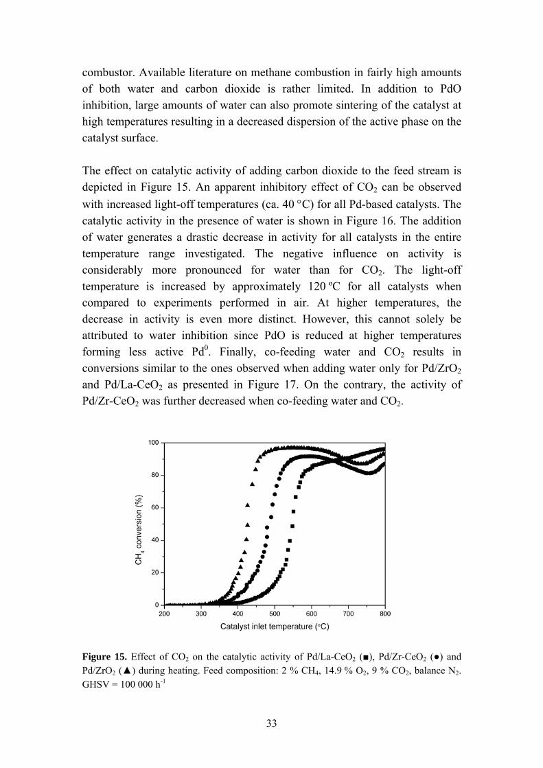
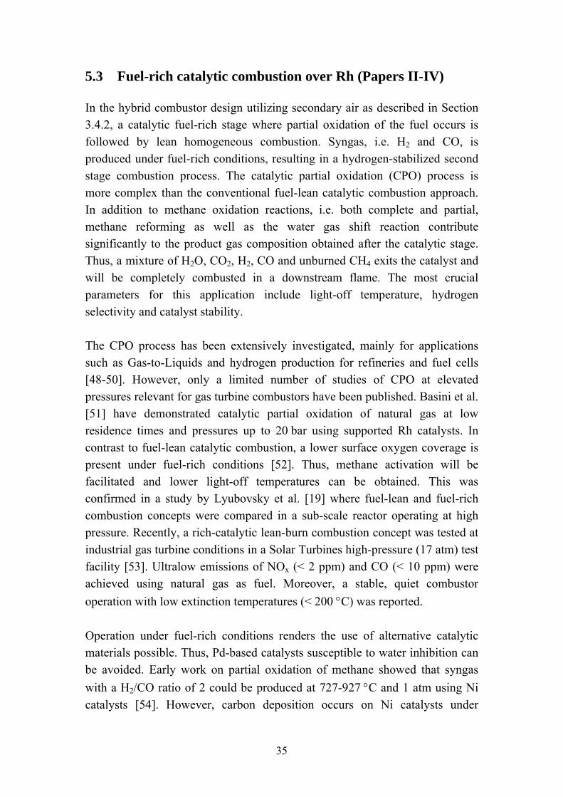
combustor. Available literature on methane combustion in fairly high amounts of both water and carbon dioxide is rather limited. In addition to PdO inhibition, large amounts of water can also promote sintering of the catalyst at high temperatures resulting in a decreased dispersion of the active phase on the catalyst surface. The effect on catalytic activity of adding carbon dioxide to the feed stream is depicted in Figure 15. An apparent inhibitory effect of CO2 can be observed with increased light-off temperatures (ca. 40 °C) for all Pd-based catalysts. The catalytic activity in the presence of water is shown in Figure 16. The addition of water generates a drastic decrease in activity for all catalysts in the entire temperature range investigated. The negative influence on activity is considerably more pronounced for water than for CO2. The light-off temperature is increased by approximately 120 ºC for all catalysts when compared to experiments performed in air. At higher temperatures, the decrease in activity is even more distinct. However, this cannot solely be attributed to water inhibition since PdO is reduced at higher temperatures forming less active Pd0. Finally, co-feeding water and CO2 results in conversions similar to the ones observed when adding water only for Pd/ZrO2
and Pd/La-CeO2 as presented in Figure 17. On the contrary, the activity of Pd/Zr-CeO2 was further decreased when co-feeding water and CO2.
Figure 15. Effect of CO2 on the catalytic activity of Pd/La-CeO2 (■), Pd/Zr-CeO2 (●) and Pd/ZrO2 (▲) during heating. Feed composition: 2 % CH4, 14.9 % O2, 9 % CO2, balance N2. GHSV = 100 000 h-1
33
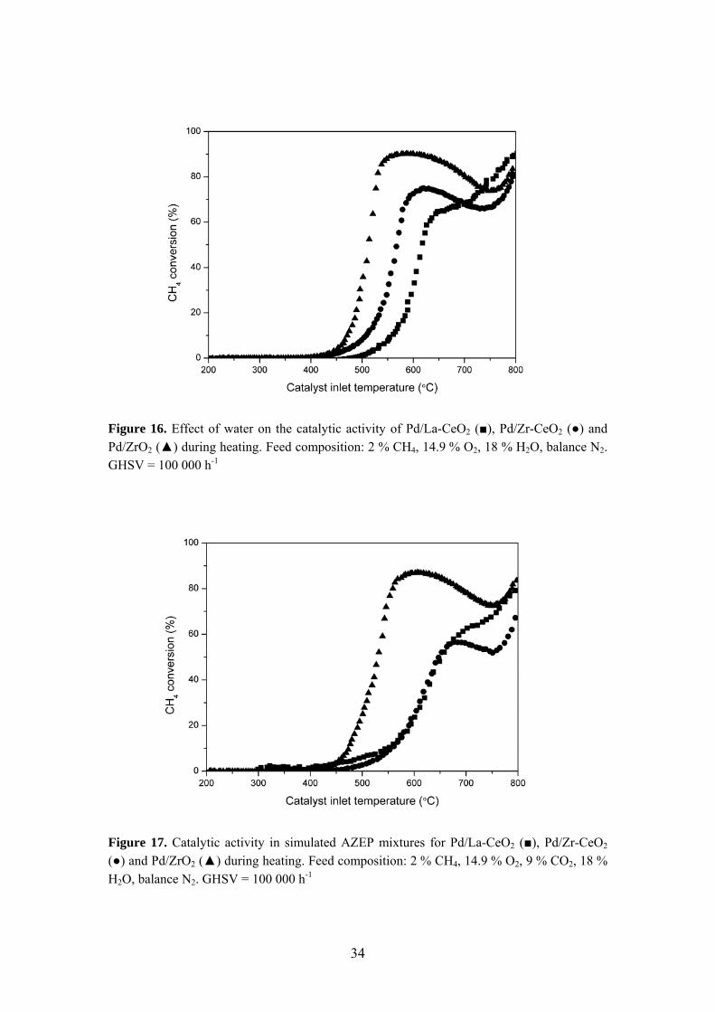
Figure 16. Effect of water on the catalytic activity of Pd/La-CeO2 (■), Pd/Zr-CeO2 (●) and Pd/ZrO2 (▲) during heating. Feed composition: 2 % CH4, 14.9 % O2, 18 % H2O, balance N2. GHSV = 100 000 h-1
Figure 17. Catalytic activity in simulated AZEP mixtures for Pd/La-CeO2 (■), Pd/Zr-CeO2 (●) and Pd/ZrO2 (▲) during heating. Feed composition: 2 % CH4, 14.9 % O2, 9 % CO2, 18 % H2O, balance N2. GHSV = 100 000 h-1
34
5.3 Fuel-rich catalytic combustion over Rh (Papers II-IV)
In the hybrid combustor design utilizing secondary air as described in Section 3.4.2, a catalytic fuel-rich stage where partial oxidation of the fuel occurs is followed by lean homogeneous combustion. Syngas, i.e. H2 and CO, is produced under fuel-rich conditions, resulting in a hydrogen-stabilized second stage combustion process. The catalytic partial oxidation (CPO) process is more complex than the conventional fuel-lean catalytic combustion approach. In addition to methane oxidation reactions, i.e. both complete and partial, methane reforming as well as the water gas shift reaction contribute significantly to the product gas composition obtained after the catalytic stage. Thus, a mixture of H2O, CO2, H2, CO and unburned CH4 exits the catalyst and will be completely combusted in a downstream flame. The most crucial parameters for this application include light-off temperature, hydrogen selectivity and catalyst stability. The CPO process has been extensively investigated, mainly for applications such as Gas-to-Liquids and hydrogen production for refineries and fuel cells [48-50]. However, only a limited number of studies of CPO at elevated pressures relevant for gas turbine combustors have been published. Basini et al. [51] have demonstrated catalytic partial oxidation of natural gas at low residence times and pressures up to 20 bar using supported Rh catalysts. In contrast to fuel-lean catalytic combustion, a lower surface oxygen coverage is present under fuel-rich conditions [52]. Thus, methane activation will be facilitated and lower light-off temperatures can be obtained. This was confirmed in a study by Lyubovsky et al. [19] where fuel-lean and fuel-rich combustion concepts were compared in a sub-scale reactor operating at high pressure. Recently, a rich-catalytic lean-burn combustion concept was tested at industrial gas turbine conditions in a Solar Turbines high-pressure (17 atm) test facility [53]. Ultralow emissions of NOx (< 2 ppm) and CO (< 10 ppm) were achieved using natural gas as fuel. Moreover, a stable, quiet combustor operation with low extinction temperatures (< 200 °C) was reported. Operation under fuel-rich conditions renders the use of alternative catalytic materials possible. Thus, Pd-based catalysts susceptible to water inhibition can be avoided. Early work on partial oxidation of methane showed that syngas with a H2/CO ratio of 2 could be produced at 727-927 °C and 1 atm using Ni catalysts [54]. However, carbon deposition occurs on Ni catalysts under
35
conditions producing syngas [55,56]. Since then, various metals including Rh, Pd, Pt, Ru, Ni, Co and Fe have been investigated as catalysts for partial oxidation of methane to syngas [57-62]. Rh-based catalysts are of particular interest due to a low vapor pressure, high specific activity and syngas selectivity as well as good resistance to carbon deposition [63,64]. In the following sections, the behavior of supported rhodium catalysts for fuel-rich combustion applications is discussed. The influence of catalyst composition (i.e. support material and noble metal loading) on methane conversion and product gas composition was studied in particular. Furthermore, catalytic combustion of exhaust gas-diluted mixtures was investigated. Supported Rh catalysts were prepared by incipient wetness impregnation using aqueous solutions of Rh(NO3)3. Coated cordierite monoliths were prepared by dip-coating and used for activity tests in the lab-scale reactor operating at atmospheric pressure as presented in Section 4.1. For high-pressure testing under AZEP conditions, spray-coated Fecralloy structures as shown in Figure 9 were used. Selected catalyst samples were characterized by H2 chemisorption, X-ray photoelectron spectroscopy (XPS), X-ray diffraction (XRD), temperature-programmed reduction (TPR) and RAMAN microscopy.
5.3.1 Influence of support material (Papers II and III)
The main function of the support material is to disperse the active metal particles and prevent sintering. However, support properties such as reducibility, acidity and oxygen transport capacity may influence the activity and stability of certain catalysts. The redox properties of the support have been particularly studied for methane oxidation and reforming reactions. For example, both the activity and the stability of Ni/Al2O3 catalysts for dry reforming of methane were improved by adding CeO2 [65]. These improvements were attributed to the redox properties of ceria, resulting in continuous removal of carbonaceous deposits by reaction with lattice oxygen forming CeO2-x. The reduced ceria is then re-oxidized by CO2. Somewhat contradictory results have been observed when studying supported Rh catalysts for partial oxidation of methane [66]. Here, it was concluded that rhodium supported on reducible oxides exhibits a lower activity and syngas selectivity than when using irreducible oxides as support. However, the Rh dispersion was
36
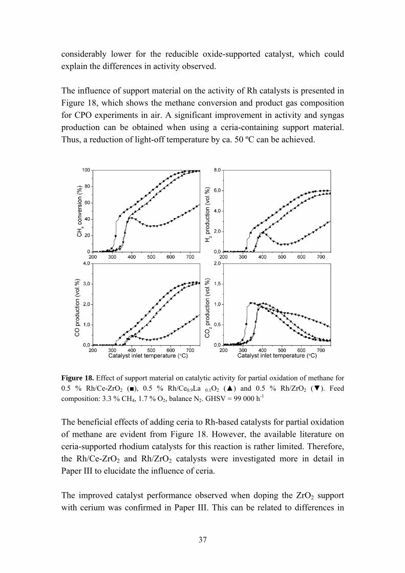
considerably lower for the reducible oxide-supported catalyst, which could explain the differences in activity observed. The influence of support material on the activity of Rh catalysts is presented in Figure 18, which shows the methane conversion and product gas composition for CPO experiments in air. A significant improvement in activity and syngas production can be obtained when using a ceria-containing support material. Thus, a reduction of light-off temperature by ca. 50 ºC can be achieved.
Figure 18. Effect of support material on catalytic activity for partial oxidation of methane for 0.5 % Rh/Ce-ZrO2 (■), 0.5 % Rh/Ce0.9La 0.1O2 (▲) and 0.5 % Rh/ZrO2 (▼). Feed composition: 3.3 % CH4, 1.7 % O2, balance N2. GHSV = 99 000 h-1
The beneficial effects of adding ceria to Rh-based catalysts for partial oxidation of methane are evident from Figure 18. However, the available literature on ceria-supported rhodium catalysts for this reaction is rather limited. Therefore, the Rh/Ce-ZrO2 and Rh/ZrO2 catalysts were investigated more in detail in Paper III to elucidate the influence of ceria. The improved catalyst performance observed when doping the ZrO2 support with cerium was confirmed in Paper III. This can be related to differences in
37
the number of accessible active surface sites of the two catalysts. Noble metal dispersions of 28 and 59 % were measured by H2 chemisorption for Rh/ZrO2 and Rh/Ce-ZrO2, respectively. Besides improving the metal dispersion, the addition of ceria will also influence the oxygen storage/release properties of the support material as already mentioned in Section 5.2.2. Mixed oxides of CeO2-ZrO2 are well known for their high oxygen mobility, which is related to the Ce4+/Ce3+ redox couple [67]. Some studies have shown that oxygen transport properties of the support material can be of importance for partial oxidation of methane [68-71]. The activity and stability of Pt/CexZr1-xO2 catalysts have been studied by Passos et al. [68]. Their work showed that the catalyst stability could be improved by increasing the oxygen storage capacity of the support. The enhanced stability was attributed to a continuous removal of carbonaceous deposits from the metal surface. No significant carbon deposition could be detected for either of the Rh-based catalysts investigated in the present work. Hence, the oxygen storage/release properties of the support material appear to be of less importance when using supported rhodium catalysts and the main effect of ceria is probably related to the enhanced noble metal dispersion.
5.3.2 Nature of active Rh sites (Paper III)
Somewhat divergent results regarding the active state of rhodium for the partial oxidation of methane have been reported. While some researchers claim that metallic Rh sites are the most active [62,63], others propose a more complex structure with Rh of different oxidation states present on the surface [72,73]. Heitnes Hofstad et al. [63] found that Rh2O3 shows low activity for syngas production and total oxidation products are mainly formed. The formation of syngas increases with time on stream since Rh reduction occurs under reaction conditions, although the extent of reduction for surface Rh atoms was not determined in this work. The importance of partially oxidized Rh species for methane dissociation, which often is considered to be the rate-limiting step for methane oxidation reactions, has been recognized [72,73]. The complex nature of the Rh species present under CPO conditions was confirmed by XPS analysis. Different Rh oxidation states, i.e. Rh0, Rhδ+ and Rh3+, may be detected on the surface depending on catalyst composition, pre-treatment and reaction environment, as presented in Table 2. The fresh catalyst samples consist of oxidized Rh species (Rh3+). The oxidized Rh/ZrO2 catalyst exhibits low activity for syngas formation (details in Paper III) in line with previously reported results [63]. Complete oxidation of methane mainly takes
38

place over this catalyst. The high activity of the fresh Rh/Ce-ZrO2 sample indicates that the formation of (partially) reduced Rh species is facilitated in the presence of ceria under reaction conditions and might occur prior to syngas initiation. After reduction treatment, considerable differences in Rh oxidation state can be observed for the two catalysts. While Rh/ZrO2 is almost completely reduced to Rh0 it is difficult to fully reduce the Rh/Ce-ZrO2 catalyst, which results in the formation of partially oxidized (Rhδ+) surface species together with Rh0. The presence of Rhδ+ for the ceria doped catalyst can be associated with a stabilization of ionic Rh species by the support. The Rhδ+
stabilizing effect is related to the Ce3+/Ce4+ redox properties of ceria that facilitates electron transfer from Rh to CeO2. The partially oxidized state (Rhδ+) promotes CH4 dissociation, which is related to its high ability to accept σ electrons of methane [74]. Table 2. Binding energies (eV) and surface atomic ratios of the catalysts after different treatments. H2 = 20 vol.% H2/N2 at 400 °C/30 min, CH4 + O2 = 3.3 vol.% CH4, 1.7 vol.% O2, balance N2 at 750 °C. * Numbers in parentheses are peak percentages.
Catalyst Treatment Rh 3d5/2* Ce/Zr at Rh/Zr at
Rh/ZrO2 fresh 309.1 - 0.008 H2 307.1 (91)
309.2 (9) - 0.006
CH4 + O2 307.6 - 0.003 Rh/Ce-ZrO2 fresh 309.0 0.228 0.029 H2 307.3 (68)
308.2 (32) 0.313 0.021
CH4 + O2 307.2 (54) 309.0 (46)
0.216 0.018
Moreover, the activation of the catalysts was investigated by exposing the catalysts to successive runs under reaction conditions. Significant disparities could be observed for the different catalysts as illustrated in Table 3. The Rh/Ce-ZrO2 catalyst exhibited a stable performance, independently of pre-treatment and number of reaction cycles. The activity of the Rh/ZrO2 catalyst, however, increased gradually during consecutive cycling. The methane
39
conversion at 750 °C increased from 39 % during the first cycle to 66 % during the third cycle. Concurrently, an almost twofold increase of the syngas selectivity occurred. Although less pronounced, this behavior could also be observed for the pre-reduced catalyst sample and a simple activation due to reduction of Rh cannot be responsible for the increase in activity. Instead, the gradual formation of highly active Rhδ+ species could explain the slow activation for Rh/ZrO2. The XPS results presented in Table 2 show a slight oxidation of Rh (307.6 eV) for the sample treated under reaction conditions compared to metallic Rh (307.1 eV). Table 3. Catalyst activation. Feed composition: 3.3 vol.% CH4, 1.7 vol.% O2, balance N2. GHSV = 99 000 h-1. * Measured at a catalyst inlet temperature of 750 °C. Catalyst Pre-
treatment Cycle
no. CH4 conversion*
(%) H2 selectivity*
(%) CO selectivity*
(%) Rh/ZrO2 fresh 1 30 45 43 2 61 76 70 3 66 81 74 reduced 1 64 81 74 2 69 85 78 3 72 79 86 Rh/Ce-ZrO2 fresh 1 97 87 96 2 97 87 96 3 97 86 96 reduced 1 97 87 96 2 97 86 96
5.3.3 Catalytic combustion in AZEP mixtures (Paper IV)
Fuel-rich catalytic combustion in actual AZEP mixtures was investigated in Paper IV using Rh-based catalysts. The experiments were conducted at elevated pressure (5 bar) to improve the resemblance to full-scale conditions. Furthermore, the effect of varying the oxygen-to-fuel ratio was studied. The activity of the catalysts was determined by slowly increasing the temperature of the inlet gas mixture (Tin) until light-off occurred, which was indicated by a rapid increase of the catalyst outlet temperature. Thereafter, the catalyst inlet temperature was decreased step-wise whilst measuring the methane conversion efficiency and outlet gas composition. The catalytic
40
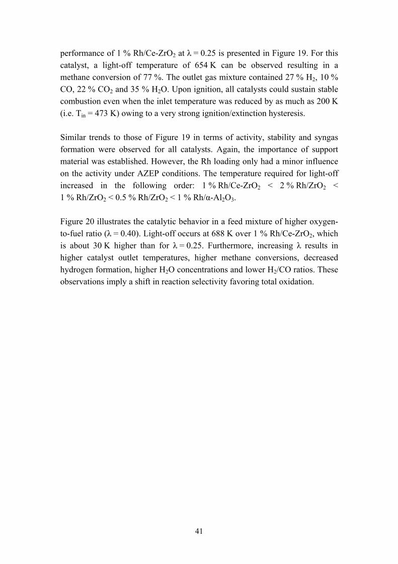
performance of 1 % Rh/Ce-ZrO2 at λ = 0.25 is presented in Figure 19. For this catalyst, a light-off temperature of 654 K can be observed resulting in a methane conversion of 77 %. The outlet gas mixture contained 27 % H2, 10 % CO, 22 % CO2 and 35 % H2O. Upon ignition, all catalysts could sustain stable combustion even when the inlet temperature was reduced by as much as 200 K (i.e. Tin = 473 K) owing to a very strong ignition/extinction hysteresis. Similar trends to those of Figure 19 in terms of activity, stability and syngas formation were observed for all catalysts. Again, the importance of support material was established. However, the Rh loading only had a minor influence on the activity under AZEP conditions. The temperature required for light-off increased in the following order: 1 % Rh/Ce-ZrO2 < 2 % Rh/ZrO2 < 1 % Rh/ZrO2 < 0.5 % Rh/ZrO2 < 1 % Rh/α-Al2O3. Figure 20 illustrates the catalytic behavior in a feed mixture of higher oxygen-to-fuel ratio (λ = 0.40). Light-off occurs at 688 K over 1 % Rh/Ce-ZrO2, which is about 30 K higher than for λ = 0.25. Furthermore, increasing λ results in higher catalyst outlet temperatures, higher methane conversions, decreased hydrogen formation, higher H2O concentrations and lower H2/CO ratios. These observations imply a shift in reaction selectivity favoring total oxidation.
41
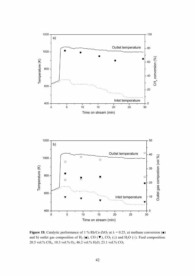
Figure 19. Catalytic performance of 1 % Rh/Ce-ZrO2 at λ = 0.25, a) methane conversion (■) and b) outlet gas composition of H2 (■), CO (▼), CO2 (□) and H2O (○). Feed composition: 20.5 vol.% CH4, 10.3 vol.% O2, 46.2 vol.% H2O, 23.1 vol.% CO2
42
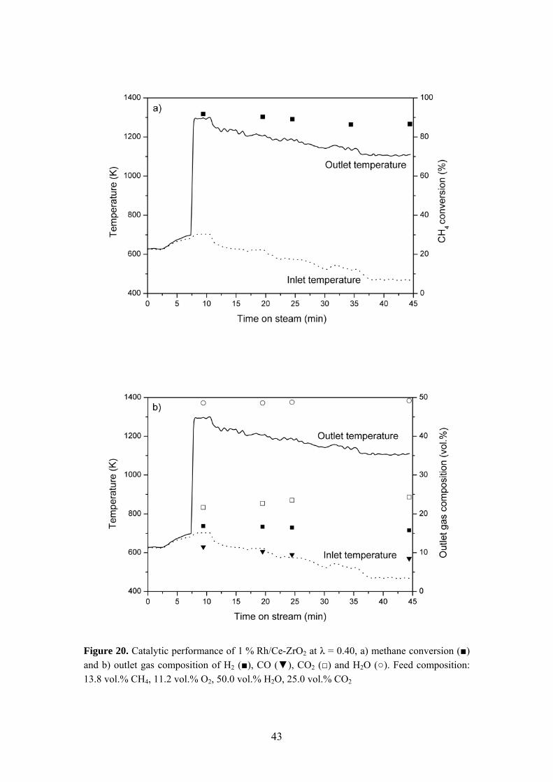
Figure 20. Catalytic performance of 1 % Rh/Ce-ZrO2 at λ = 0.40, a) methane conversion (■) and b) outlet gas composition of H2 (■), CO (▼), CO2 (□) and H2O (○). Feed composition: 13.8 vol.% CH4, 11.2 vol.% O2, 50.0 vol.% H2O, 25.0 vol.% CO2
43
5.3.4 Reaction mechanism (Papers III and IV)
Elucidation of the reaction mechanism for partial oxidation of methane is of importance for catalyst design purposes related to thermal management issues. While some researchers propose a direct reaction pathway forming CO and H2 as primary products according to the mildly exothermic reaction (1), other studies support the indirect reaction mechanism consisting of complete combustion (2) followed by methane dry (3) and steam (4) reforming [62,63,75-78]. The strong exothermicity of the methane combustion reaction may result in hot spot formation, primarily in the catalyst entrance zone. CH4 + 1/2O2 ↔ CO + 2H2 ΔH298 = -36 kJ/mol (1) CH4 + 2O2 ↔ CO2 + 2H2O ΔH298 = -890 kJ/mol (2) CH4 + CO2 ↔ 2CO + 2H2 ΔH298 = 247 kJ/mol (3) CH4 + H2O ↔ CO + 3H2 ΔH298 = 250 kJ/mol (4) The CPO reaction mechanism is not straightforward and depends on reaction conditions, catalyst composition, state of active metal and surface species present [79,80]. The reaction mechanism over Rh/Ce-ZrO2 was studied by observing the product formation sequence as depicted in Figure 21. The results show that CO2 is formed immediately after that methane consumption is initiated. The CO2 production reaches a maximum at 350 °C, which is followed by a gradual decline to zero formation at 750 °C. Syngas formation is initiated at a higher temperature and increases continuously with rising temperature. These observations are in line with the indirect reaction mechanism. This reaction route was also implied for the rhodium catalysts studied under AZEP conditions.
44
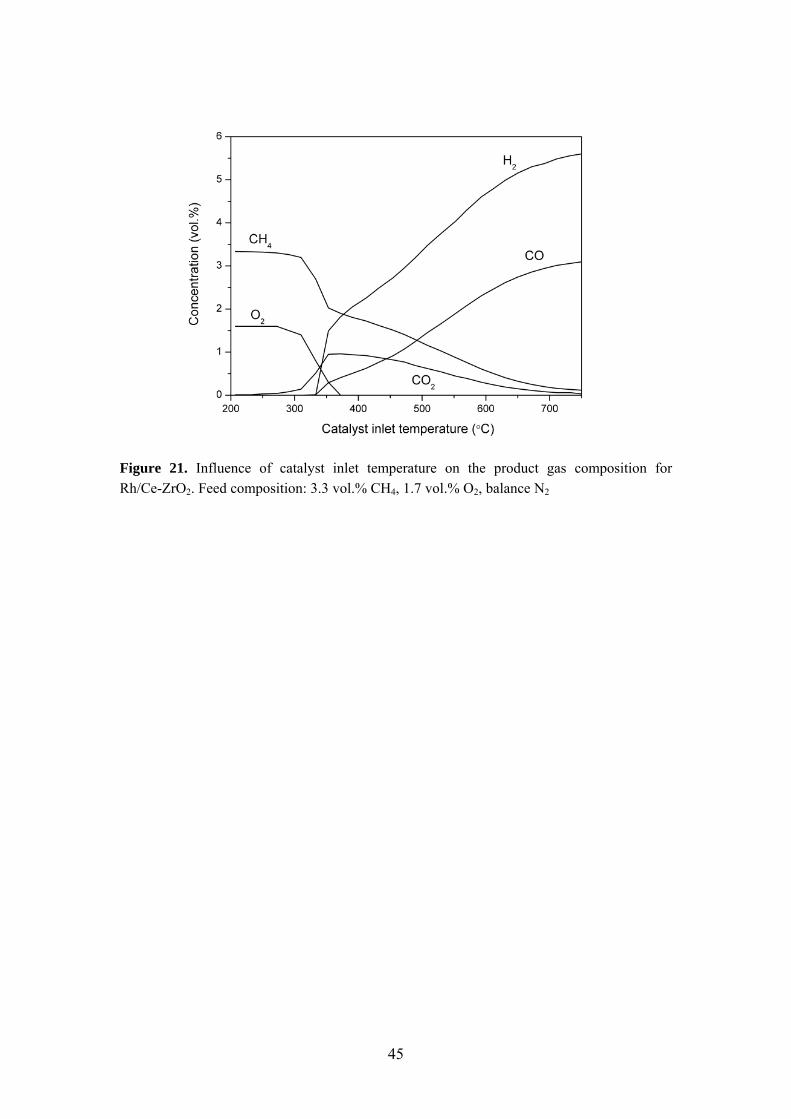
Figure 21. Influence of catalyst inlet temperature on the product gas composition for Rh/Ce-ZrO2. Feed composition: 3.3 vol.% CH4, 1.7 vol.% O2, balance N2
45

46
Chapter 6
Numerical Investigation of
Catalytic Combustion (Paper V)
6.1 Introduction
The development of reliable models for catalytic combustion is of interest for reactor design and process optimization purposes. The fuel-rich combustion approach is of high complexity with different reactions occurring along the reactor as outlined in Section 5.3.4. Thus, detailed reaction schemes are required to accurately describe the catalytic partial oxidation stage. Recently, elementary heterogeneous reaction schemes for CPO of methane over Rh and Pt have been developed [81-83]. In Paper V, the partial oxidation of methane over supported Rh catalysts was investigated, including both high-pressure experiments and numerical predictions. The experiments were performed under AZEP conditions as detailed in Section 5.3.3. The computations were carried out using a 2-D elliptic CFD code with elementary heterogeneous and homogeneous reaction schemes and detailed transport. The main objective was to validate the numerical model for CPO over different catalyst compositions in terms of methane conversion and synthesis gas production.
47
6.2 Numerical model
A steady, two-dimensional, full elliptic laminar numerical code was used that included detailed hetero-/homogeneous chemistry and transport, as well as heat transfer mechanisms in the solid. A single-channel model was adopted where each channel was modeled as a cylindrical tube. This was an adequate approach considering the good thermal insulation and the uniform inlet properties at the reactor entry. The reactor adiabaticity was also attested experimentally by comparing the inlet and outlet total enthalpies, deduced from measured temperatures and species concentrations. The gas-phase governing equations have been solved in their cylindrical coordinates as presented below. Continuity:
0)(1)(=
∂∂
+∂
∂rvr
rxu ρρ
Momentum (axial, radial):
⎟⎠⎞
⎜⎝⎛ +
∂∂
+
⎥⎦
⎤⎢⎣
⎡⎟⎠⎞
⎜⎝⎛
∂∂
+∂∂
−∂∂
∂∂
+⎥⎦
⎤⎢⎣
⎡⎟⎠⎞
⎜⎝⎛
∂∂
+∂∂
∂∂
+∂∂
−=∂
∂+
∂∂
⎥⎦
⎤⎢⎣
⎡⎟⎠⎞
⎜⎝⎛
∂∂
+∂∂
∂∂
+
⎥⎦
⎤⎢⎣
⎡⎟⎠⎞
⎜⎝⎛
∂∂
+∂∂
−∂∂
∂∂
+∂∂
−=∂
∂+
∂∂
rv
rv
r
rrv
rxu
rv
rru
xv
xrp
rvvr
rxuv
xv
rur
rr
rrv
rxu
xu
xxp
rvur
rxuu
μ
μμμρρ
μ
μμρρ
2
)(1322)(1)(
1
)(1322)(1)(
Total enthalpy:
⎟⎟⎠
⎞⎜⎜⎝
⎛−
∂∂
∂∂
+
⎟⎟⎠
⎞⎜⎜⎝
⎛−
∂∂
∂∂
=∂
∂+
∂∂
∑
∑
=
=
g
g
K
krkkkg
K
kxkkkg
VhYrrTr
rr
VhYxT
xrvhr
xuh
1,
1,
1
)()(
ρλ
ρλρρ
Species:
( ) ( ) kkrkkxkkkk WVYr
rrVY
xrvYr
rxuY
ωρρρρ
&+∂∂
−∂∂
−=∂
∂+
∂∂
,,1)(1)(
k = 1,…, Kg.
48
Surface species coverage equations:
Γ=
∂∂ m
mm st
&σ
θ m = 1,…, Ms.
Only the steady-state solutions were of interest. Buoyancy was insignificant for the relatively high Reynolds numbers present (ReIN = 590-755). The species’ diffusion velocities were computed using mixture-average, including thermal diffusion for the light species [84]:
kVr
TTYDYYDV kTkkkkmk ∇+∇−= )/()/( ρr , k = 1,…, Kg.
The system of equations was closed by the ideal gas and caloric state laws:
WRTp ρ
= and k = 1,…, K( ) ∫+=T
Tkpkk dTcThh
0
,,00
g.
A 2-D model was used for steady solid heat conduction in the solid substrate of a representative honeycomb channel (solid thickness δ /2 + cδ = 29.6 μm):
0)(1)( 2
2
=⎥⎦⎤
⎢⎣⎡
∂∂
∂∂
+∂ r
Trr
rrxT
r Ws
Ws λ
∂λ ,
with )(rsλ = 0.4 Wm-1K-1 for rh < r ≤ rh + cδ (ZrO2 porous washcoat) and
)(rsλ = 16 Wm-1K-1 for rh+ cδ < r < rh + cδ + δ /2 (Fecralloy). The interfacial energy boundary condition of a representative honeycomb channel (r = rh) was:
( ) 0)()(1
rad =++−=== ∑
=+− h
g
hs
hg
rr
K
rrrr kkkkWW WhsBrTrTq && ρ∂∂λ∂∂λ
The term q represents the radiation exchange of each differential cylindrical surface element with all other differential surface elements as well as with the channel entry and outlet. The radiation exchange temperatures for the entry and outlet of the channel were equal to the corresponding mean gas temperatures. The gas-phase species’ interfacial boundary conditions were:
& rad
hrrrkkVY
=)( ,ρ + B = 0, k = 1,…, Kkk sW & g,
with over the inactive channel length. The factor B signifies the ratio of the active to the geometrical surface area and was determined by H
0=ks&
2 chemisorption measurements of used catalyst samples. Intraphase species diffusion was not considered because the catalyst layer was only 4.6 μm thick
49
and was applied on non-porous Fecralloy surfaces. Radiative boundary conditions were applied at the reactor inlet and outlet: εσ∂λ =∂xTr Ws )( [ ] at x = –L44
IN)( TxTW − u , rh < r ≤ rh + cδ + δ /2
− εσ∂λ =∂xTr Ws )( [ ] at x = L4OUT
4 )( TxTW − c+Lu , rh < r ≤ rh + cδ + δ /2 The outer channel wall surfaces were treated as adiabatic ( 0/ =rTW ∂∂ at
r = rh + cδ + δ /2), to account for the adjacent honeycomb channels. Uniform profiles for the axial velocity, the species’ mass fractions and the temperature were specified at the inlet. At the axis of symmetry (r = 0) and the channel outlet (x = Lc+Lu) zero-Neumann boundary conditions were used for all thermoscalars and the axial velocity, while the radial velocity was set to zero. Finally, no-slip has been applied for both velocity components at r = rh. A finite volume scheme was used to discretize the governing equations and the solution was obtained iteratively using a SIMPLER [85] method for the pressure-velocity field. Details on the solution algorithm can be found elsewhere [86-88]. An orthogonal staggered grid of 220x24 points in x and r, respectively, (75 mm x 0.6 mm) with finer x-spacing closer to the entry and r-spacing closer to the wall was used for the honeycomb channel, which was sufficient to produce a grid-independent solution. The solid was discretized with 220x16 points (75 mm x 0.031 mm). The detailed heterogeneous reaction mechanism of Deutschmann [83] presented in Table 4 was used for CPO of methane over rhodium (38 reactions, 12 surface and 6 gas species). Earlier studies of CPO have shown that this reaction scheme reproduced the methane conversion and synthesis gas yields over Rh-based catalysts [89,90]. The gaseous chemistry was described by the C2/H/O homogeneous reaction mechanism of Warnatz [91]. However, simulations of the present honeycomb experiments with the above hetero-/homogeneous mechanisms have shown that gas-phase chemistry was unimportant. The CHEMKIN database was used to evaluate transport properties [84] whereas surface and gas-phase reaction rates were evaluated with SURFACE CHEMKIN [92] and CHEMKIN [93], respectively.
50
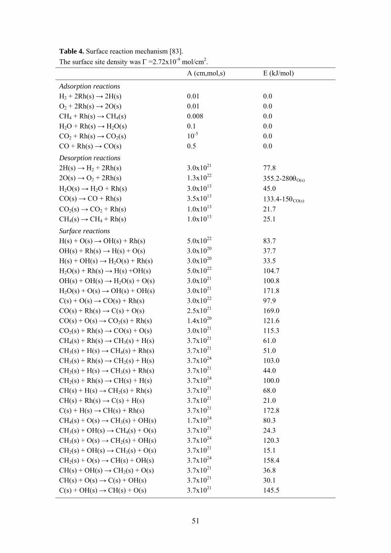
Table 4. Surface reaction mechanism [83]. The surface site density was Γ =2.72x10⁻⁹ mol/cm2. A (cm,mol,s) E (kJ/mol)
Adsorption reactions H2 + 2Rh(s) → 2H(s) 0.01 0.0 O2 + 2Rh(s) → 2O(s) 0.01 0.0 CH4 + Rh(s) → CH4(s) 0.008 0.0 H2O + Rh(s) → H2O(s) 0.1 0.0 CO2 + Rh(s) → CO2(s) 10-5 0.0 CO + Rh(s) → CO(s) 0.5 0.0
Desorption reactions 2H(s) → H2 + 2Rh(s) 3.0x10²¹ 77.8 2O(s) → O2 + 2Rh(s) 1.3x10²² 355.2-280θO(s)
H2O(s) → H2O + Rh(s) 3.0x10¹³ 45.0 CO(s) → CO + Rh(s) 3.5x10¹³ 133.4-15θCO(s)
CO2(s) → CO2 + Rh(s) 1.0x10¹³ 21.7 CH4(s) → CH4 + Rh(s) 1.0x10¹³ 25.1
Surface reactions H(s) + O(s) → OH(s) + Rh(s) 5.0x10²² 83.7 OH(s) + Rh(s) → H(s) + O(s) 3.0x10²⁰ 37.7 H(s) + OH(s) → H2O(s) + Rh(s) 3.0x10²⁰ 33.5 H2O(s) + Rh(s) → H(s) +OH(s) 5.0x10²² 104.7 OH(s) + OH(s) → H2O(s) + O(s) 3.0x10²¹ 100.8 H2O(s) + O(s) → OH(s) + OH(s) 3.0x10²¹ 171.8 C(s) + O(s) → CO(s) + Rh(s) 3.0x10²² 97.9 CO(s) + Rh(s) → C(s) + O(s) 2.5x10²¹ 169.0 CO(s) + O(s) → CO2(s) + Rh(s) 1.4x10²⁰ 121.6 CO2(s) + Rh(s) → CO(s) + O(s) 3.0x10²¹ 115.3 CH4(s) + Rh(s) → CH3(s) + H(s) 3.7x10²¹ 61.0 CH3(s) + H(s) → CH4(s) + Rh(s) 3.7x10²¹ 51.0 CH3(s) + Rh(s) → CH2(s) + H(s) 3.7x1024 103.0 CH2(s) + H(s) → CH3(s) + Rh(s) 3.7x10²¹ 44.0 CH2(s) + Rh(s) → CH(s) + H(s) 3.7x1024 100.0 CH(s) + H(s) → CH2(s) + Rh(s) 3.7x10²¹ 68.0 CH(s) + Rh(s) → C(s) + H(s) 3.7x10²¹ 21.0 C(s) + H(s) → CH(s) + Rh(s) 3.7x10²¹ 172.8 CH4(s) + O(s) → CH3(s) + OH(s) 1.7x1024 80.3 CH3(s) + OH(s) → CH4(s) + O(s) 3.7x10²¹ 24.3 CH3(s) + O(s) → CH2(s) + OH(s) 3.7x1024 120.3 CH2(s) + OH(s) → CH3(s) + O(s) 3.7x10²¹ 15.1 CH2(s) + O(s) → CH(s) + OH(s) 3.7x1024 158.4 CH(s) + OH(s) → CH2(s) + O(s) 3.7x10²¹ 36.8 CH(s) + O(s) → C(s) + OH(s) 3.7x10²¹ 30.1 C(s) + OH(s) → CH(s) + O(s) 3.7x10²¹ 145.5
51
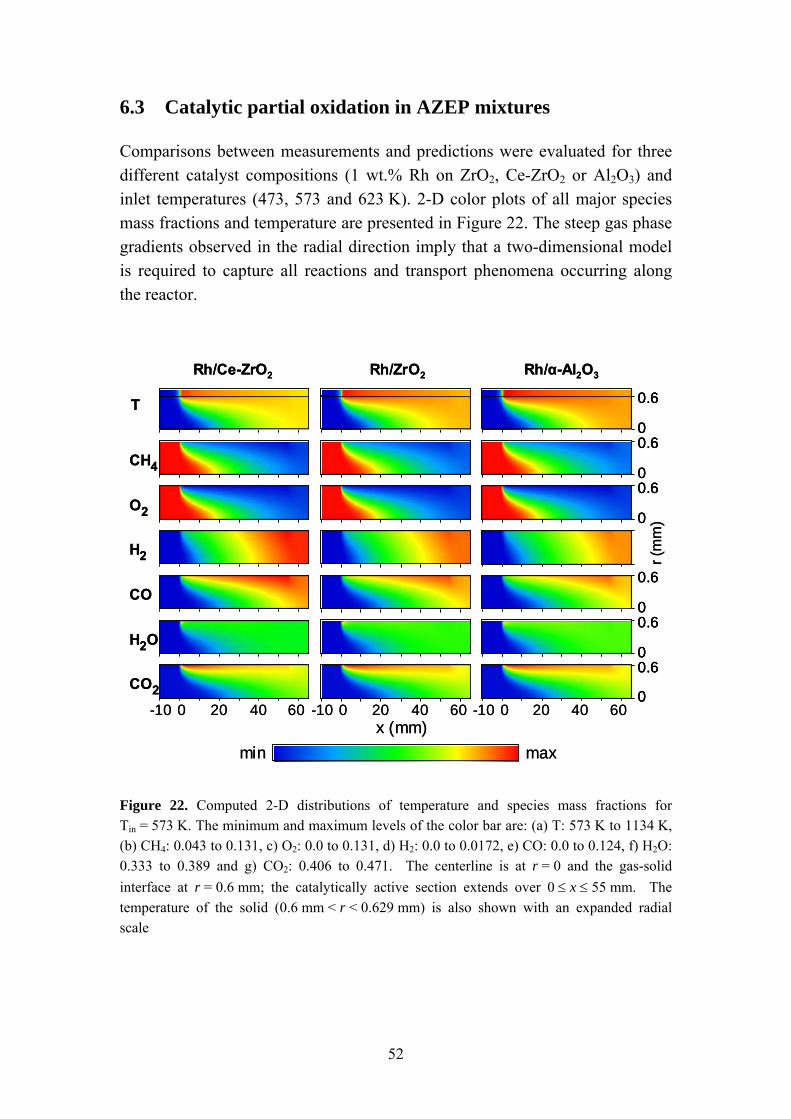
6.3 Catalytic partial oxidation in AZEP mixtures
Comparisons between measurements and predictions were evaluated for three different catalyst compositions (1 wt.% Rh on ZrO2, Ce-ZrO2 or Al2O3) and inlet temperatures (473, 573 and 623 K). 2-D color plots of all major species mass fractions and temperature are presented in Figure 22. The steep gas phase gradients observed in the radial direction imply that a two-dimensional model is required to capture all reactions and transport phenomena occurring along the reactor.
Rh/α-Al2O3Rh/ZrO2Rh/Ce-ZrO2
min max
T
CH4
O2
CO2
H2
CO
H2O
0.6
00.6
0
0.6
00.6
00.6
0
r (m
m)
-10 0 20 40 60 -10 0 20 40 60 -10 0 20 40 60
0.6
0
x (mm)
Rh/α-Al2O3Rh/ZrO2Rh/Ce-ZrO2
min max
T
CH4
O2
CO2
H2
CO
H2O
0.6
0
0.6
00.6
0
0.6
0
0.6
0
0.6
00.6
0
0.6
00.6
0
0.6
0
r (m
m)
-10 0 20 40 60 -10 0 20 40 60 -10 0 20 40 60
0.6
0
0.6
0
x (mm)
Figure 22. Computed 2-D distributions of temperature and species mass fractions for Tin = 573 K. The minimum and maximum levels of the color bar are: (a) T: 573 K to 1134 K, (b) CH4: 0.043 to 0.131, c) O2: 0.0 to 0.131, d) H2: 0.0 to 0.0172, e) CO: 0.0 to 0.124, f) H2O: 0.333 to 0.389 and g) CO2: 0.406 to 0.471. The centerline is at r = 0 and the gas-solid interface at r = 0.6 mm; the catalytically active section extends over 0 ≤ x ≤ 55 mm. The temperature of the solid (0.6 mm < r < 0.629 mm) is also shown with an expanded radial scale
52
The maximum in H2O and CO2 mass fractions, together with peak wall temperatures observed at the entry of the catalytically active channel (x = 0), indicates that complete oxidation of methane occurs here for all cases. However, the presence of H2 and CO at x ≈ 0 implies that partial oxidation also takes place to some extent. The increased importance of methane reforming along the channel was demonstrated by a continuous decrease in wall temperature and enhanced synthesis gas yields. The outlet composition and temperature for both measurements and predictions are summarized for all cases in Table 5. In general, a good agreement between simulations and experimental results was obtained for all catalysts. For inlet temperatures of 623 or 573 K, the relative difference in species concentrations between experiments and simulations were less than 10 %, with the exception of O2. A somewhat worse agreement was observed for Tin = 473 K, resulting in differences as high as 15 %. A slight over/underprediction of H2O/H2 can be observed for all cases. The importance of noble metal dispersion for synthesis gas production, as previously discussed in Section 5.3.1, was supported both by predictions as well as measurements. Increasing the Rh dispersion (Ce-ZrO2 > ZrO2 > α-Al2O3) resulted in slightly higher methane conversions, lower surface temperatures, higher H2 and CO yields and correspondingly lower H2O and CO2 concentrations, for the same inlet conditions. Thus, the model can be employed to describe the behavior of supported Rh catalysts for CPO of methane in exhaust gas diluted mixtures, especially at gas turbine-relevant conditions with Tin ≥ 623 K. The catalytic performance, i.e. methane conversion, synthesis gas production and temperature, can be predicted by changing the factor B in the model according to noble metal dispersion measurements.
53

Table 5. Comparison between experiments and simulations. Measured and predicted volumetric exhaust composition (%) and outlet temperature (Tout).
Catalyst support
Tin (K) CH4 O2 H2 CO H2O CO2 Tout (K)
Exp. Sim. Exp. Sim. Exp. Sim. Exp. Sim. Exp. Sim. Exp. Sim. Exp. Sim. Ce-ZrO2 623 6.0 6.4 0.1 0.8 21.0 19.9 8.8 8.6 41.4 42.0 22.7 22.3 1033 1007 Ce-ZrO2 573 6.5 7.1 0.2 0.8 19.9 17.9 8.1 8.4 42.1 43.4 23.2 22.3 1022 992 Ce-ZrO2 473 7.4 8.6 0.2 1.0 16.8 14.3 8.2 7.7 44.2 46.0 23.2 22.4 978 961
ZrO2 623 6.8 6.9 0.5 0.8 19.4 18.7 8.3 8.2 42.1 42.8 22.9 22.6 1031 1032 ZrO2 573 7.5 7.6 0.6 0.8 17.9 16.8 7.5 7.9 43.3 44.2 23.2 22.6 1027 1015 ZrO2 473 8.8 9.3 0.6 1.0 14.9 12.7 6.8 7.1 45.1 47.1 23.8 22.8 994 994
α-Al2O3 623 7.5 7.2 0.9 0.8 18.9 18.1 7.8 8.0 42.1 43.3 22.8 22.7 1020 1045 α-Al2O3 573 8.1 7.9 1.1 0.9 16.9 16.2 7.5 7.7 43.1 44.6 23.3 22.7 997 1028 α-Al2O3 473 9.7 9.3 1.4 1.0 13.5 12.7 6.2 7.1 45.3 47.1 23.9 22.8 964 994
54

Chapter 7
Conclusions Catalytic combustion for the generation of heat and power is at its early stage of commercialization. Successful demonstrations of using this ultralow-emission combustion technology for natural gas-fired gas turbines have attracted a strong interest from industry. However, further development of catalytic combustors is required to improve the technique and expand the field of application. An important issue that still needs to be resolved is the development of catalysts with improved low-temperature activity, thus avoiding the need for pre-burners that generate NOx. Moreover, novel combustion concepts have emerged lately resulting in the need for alternative catalytic systems. The combustor concept utilizing secondary air resulting in fuel-rich catalytic combustion is an example. Also, the flexibility of the combustor should be improved to meet variations in load, ambient conditions and gas turbine size. The main objective of this thesis was to investigate suitable catalysts for the oxidation of methane in gas turbine combustors. Two different catalytic combustion concepts have been investigated, i.e. fuel-lean and fuel-rich combustion of methane. In order to simulate a combustion process utilizing exhaust gas recirculation, the effect of water and CO2 on the catalyst performance was studied in particular. Significant differences in activity for
55
methane oxidation and product gas composition could be detected for the different configurations and catalyst compositions. Supported Pd catalysts (Pd on ZrO2, La-CeO2 or Zr-CeO2) were selected for studying combustion under fuel-lean conditions due to their superior activity for methane oxidation in excess air compared to other noble metals. The activity of Pd catalysts for methane combustion was found to strongly depend on support material, which may be attributed to differences in PdO particle size. The lowest light-off temperature was obtained for Pd/ZrO2 under all conditions studied. The order of activity changed at higher temperatures resulting in Pd/La-CeO2 being the most active catalyst above ca. 700 °C. This catalyst also shows a more stable performance with no distinct deactivation occurring at higher temperatures during cooling, which can be attributed to both support material activity and a stabilization of the active PdO phase by oxygen transfer from the support material. A severe drop in activity can be observed for Pd/ZrO2 and Pd/Zr-CeO2 at around 700 ºC during cooling, which could lead to instabilities during gas turbine operation. Combustion in exhaust gas-diluted mixtures using Pd-based catalysts represents a challenging task. Both water and CO2 have a negative effect on the catalytic activity. However, modifying the catalyst by changing support material can have a significant influence on the performance. Furthermore, a staged combustion system with Pd/ZrO2 as light-off catalyst followed by Pd/La-CeO2 at higher temperatures might be suitable. Operation under fuel-rich conditions renders the use of alternative catalytic materials possible. Thus, Pd-based catalysts susceptible to water inhibition can be avoided. In this combustion concept, a catalytic fuel-rich stage where partial oxidation of the fuel occurs is followed by lean homogeneous combustion. Syngas, i.e. H2 and CO, is produced under fuel-rich conditions, resulting in a hydrogen-stabilized second stage combustion process. The results obtained show that a hybrid combustor design consisting of a fuel-rich catalytic stage followed by H2-stabilized homogeneous combustion is a promising combustion method for concepts utilizing exhaust gas recirculation. Supported rhodium catalysts were found to be suitable for the light-off stage in feed mixtures heavily diluted with water and CO2. These materials are less sensitive to water causing catalyst deactivation, in contrast to the fuel-lean
56
approach using Pd catalysts. Moreover, additional hydrogen can be produced by steam and dry reforming under fuel-rich AZEP conditions. The most suitable catalyst identified for fuel-rich catalytic combustion of methane consists of rhodium supported on ceria-doped ZrO2. Benefits such as low light-off temperature, high activity and improved hydrogen selectivity could be observed. Furthermore, the Rh/Ce-ZrO2 catalyst exhibited a high activity regardless of pre-treatment. Thus, no activation period is required to obtain a high activity in contrast to conditions for Rh/ZrO2. Another important observation regarding catalyst stability could be made under fuel-rich AZEP conditions. Upon ignition, all catalysts could sustain stable combustion even when the inlet temperature was reduced by as much as 200 K (i.e. Tin = 473 K) owing to the very strong ignition/extinction hysteresis. Hence, the risk of stability problems during part-load operation, i.e. lower combustor inlet temperatures, can be avoided. Finally, a numerical investigation of the fuel-rich catalytic combustion concept was conducted. Measurements and predictions for catalytic partial oxidation in exhaust gas-diluted mixtures were compared. The computations were carried out using a 2-D elliptic CFD code with elementary heterogeneous and homogeneous reaction schemes and detailed transport. In general, a good agreement between simulations and experimental results was obtained for all catalyst compositions, especially at higher inlet temperatures relevant for gas turbine combustors. Thus, the model can be employed to describe the behavior of supported Rh catalysts for partial oxidation of methane in exhaust gas diluted mixtures. The catalytic performance, i.e. methane conversion, synthesis gas production and temperature, can be predicted for different catalyst compositions by changing the model according to results of noble metal dispersion measurements.
57

58
Acknowledgements I would like to thank Professor Sven Järås for giving me the opportunity to carry out my graduate studies at the Department of Chemical Engineering and Technology at KTH. I also thank Associate Professor Magali Boutonnet for her supervision. I want to thank my colleagues, former and present, at Chemical Technology and Chemical Reaction Engineering for providing a positive working environment and good friendship. Special thanks to Katarina, Ulf, Erik, Sergio, Anders and Stelios for stimulating collaboration. Also thanks to Marita and Bård for being good room-mates. I am grateful to Christina Hörnell and Michel Bellais for improving the linguistic quality of the thesis, and to Inga Groth for assistance with BET and XRD analysis. I would also like to thank the undergraduate students whom I had the opportunity to work with, Marita Nilsson and Andrea Scarabello, for doing an excellent job. The financial support from the European Commission, contract number ENK5-CT-2001-00514, and the Swiss Government (BBW01.0054-1) is gratefully acknowledged. I want to thank the partners in the AZEP project with whom I had the pleasure to work, especially Markus Wolf and Raffaella Villa at ALSTOM Power and Ioannis Mantzaras and Adrian Schneider at the Paul Scherrer Institute. Last, but not least, I would like to thank my family and friends for support and encouragement during the years.
59

60
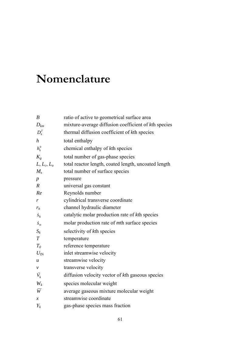
Nomenclature B ratio of active to geometrical surface area Dkm mixture-average diffusion coefficient of kth species
TkD thermal diffusion coefficient of kth species
h total enthalpy 0kh chemical enthalpy of kth species
Kg total number of gas-phase species L, Lc, Lu total reactor length, coated length, uncoated length Ms total number of surface species p pressure R universal gas constant Re Reynolds number r cylindrical transverse coordinate rh channel hydraulic diameter &sk catalytic molar production rate of kth species
ms& molar production rate of mth surface species Sk selectivity of kth species T temperature T0 reference temperature UIN inlet streamwise velocity u streamwise velocity v transverse velocity v
Vk diffusion velocity vector of kth gaseous species Wk species molecular weight W average gaseous mixture molecular weight x streamwise coordinate Yk gas-phase species mass fraction
61
Greek Symbols δ channel solid wall thickness δc catalyst layer thickness ε surface emissivity λg , λs thermal conductivity of gas and solid λ oxygen-to-fuel ratio ρ density ϕ fuel-to-air equivalence ratio μ viscosity
kω& gas-phase species molar production rate
mθ coverage of mth surface species
mσ number of occupied surface sites of mth species σ Stefan-Boltzmann constant Γ Surface site density Subscripts IN, OUT inlet, outlet W wall Abbreviations AZEP advanced zero emission power CPO catalytic partial oxidation GHSV gas hourly space velocity TPO temperature-programmed oxidation TPR temperature-programmed reduction XPS X-ray photoelectron spectroscopy XRD X-ray diffraction
62
References 1. H. Cohen, G.F.C. Rogers, H.I.H. Saravanamuttoo, Gas turbine theory 4th
ed., Addison Wesley Longman Limited, Essex, 1996. 2. C.E. Baukal, Industrial combustion pollution and control, Marcel Dekker,
New York, 2004. 3. P. Thevenin, Catalytic combustion of methane, PhD thesis, KTH-
Kungliga Tekniska Högskolan, Department of Chemical Engineering and Technology, Stockholm, 2002.
4. European Commission, http://europa.eu.int/comm/environment/climat/kyoto.htm, accessed 2006-11-06.
5. Carbon Dioxide Capture and Storage, Report of DTI International Technology Service Mission to the USA and Canada from 27th October to 7th November 2002.
6. M. Reinke, R. Carroni, D. Winkler, T. Griffin, Experimental Investigation of Natural Gas Combustion in Oxygen / Exhaust Gas Mixtures for Zero Emissions Power Generation, 6th Int. Conf. on Technologies and Combustion for a Clean Environment, 9-12 July, 2001, Oporto, Portugal, 1:15.
7. T. Griffin, S.G. Sundkvist, K. Åsen, T. Bruun, Advanced Zero Emissions Gas Turbine Power Plant, ASME TURBO EXPO, 16-19 June, 2003, Atlanta, Georgia, USA.
8. H. Audus, O. Kaarstad, G. Skinner, CO2 Capture by Pre-Combustion Decarbonisation of Natural Gas, IEA GHG Paper presented at GHGT-4, Interlaken, Switzerland, 1998.
9. W.C. Pfefferle, Belgian Patent 814 (1974), to Engelhard Corporation. 10. W.C. Pfefferle, J. Energy 2 (1978) 142.
63
11. R.E. Hayes, S.T. Kolaczkowski, Introduction to catalytic combustion, Gordan and Breach Science Publishers, Amsterdam, 1997.
12. E.M. Johansson, D. Papadias, P.O. Thevenin, A.G. Ersson, R. Gabrielsson, P.G. Menon, P.H. Björnbom, S.G. Järås, Catal. Special. Period. Rep. R. Soc. Chem. 14 (1999) 183.
13. B. Beguin, E. Garbowski, M. Primet, J. Catal. 127 (1991) 595. 14. M.F.M. Zwinkels, S.G. Järås, P.G. Menon, T.A. Griffin, Catal. Rev. –Sci.
Eng. 35 (1993) 319. 15. R. Carroni, V. Schmidt, T. Griffin, Catal. Today 75 (2002) 287. 16. D.Y. Yee, K. Lundberg, C.K. Weakley, ASME Paper 2000-GT-0088,
2000. 17. Catalytica Energy Systems,
http://www.catalyticaenergy.com/xonon/index.html, accessed 2005-01-13. 18. D.B. Fant, G.S. Jackson, H. Karim, D.M. Newburry, P. Dutta, K.O.
Smith, R.W. Dibble, ASME Paper 99-GT-57. 19. M. Lyubovsky, L.L. Smith, M. Castaldi, H. Karim, B. Nentwick, S.
Etemad, R. LaPierre, W.C. Pfefferle, Catal. Today 83 (2003) 71. 20. T. Griffin, D. Winkler, M. Wolf, C. Appel, J. Mantzaras, ASME (2004)
54101. 21. T.V. Choudhary, S. Banerjee, V.R. Choudhary, Appl. Catal. A 234
(2002) 1. 22. R. Prasad, L.A. Kennedy, E. Ruckenstein, Catal. Rev. –Sci. Eng. 26
(1984) 1. 23. G. Pecchi, P. Reyes, R. Gómez, T. López, J.L.G. Fierro, Appl. Catal. B 17
(1998) L7. 24. G.J.K. Acres, B. Harrison, Top. Catal. 28 (2004) 3. 25. M.V. Twigg, Catal. Today 117 (2006) 407. 26. K.H. Hofstad, J.H.B.J. Hoebink, A. Holmen, G.B. Marin, Catal. Today 40
(1998) 157. 27. F. Basile, G. Fornasari, F. Trifiro, A. Vaccari, Catal. Today 64 (2001) 21. 28. R.F. Hicks, H. Qi, M.L. Young, R.G. Lee, J. Catal. 122 (1990) 295. 29. P. Briot, M. Primet, Appl. Catal. 68 (1991) 301. 30. R.F. Hicks, H. Qi, M.L. Young, R.G. Lee, J. Catal. 122 (1990) 280. 31. F.H. Ribeiro, M. Chow, R.A. Dalla Betta, J. Catal. 146 (1994) 537. 32. R.J. Farrauto, M.C. Hobson, T. Kennelly, E.M. Waterman, Appl. Catal. A
81 (1992) 227. 33. R. Burch, F.J. Urbano, Appl. Catal. A 124 (1995) 121. 34. S.C. Su, J.N. Carstens, A.T. Bell, J. Catal. 176 (1998) 125.
64
35. R.J. Farrauto, J.K. Lampert, M.C. Hobson, E.M. Waterman, Appl. Catal. B 6 (1995) 263.
36. G. Groppi, G. Artioli, C. Cristiani, L. Lietti, P. Forzatti, Stud. Surf. Sci. Catal. 136 (2001) 345.
37. C. Bozo, N. Guilhaume, E. Garbowski, M. Primet, Catal. Today 59 (2000) 33.
38. M. O’Connell, M.A. Morris, Catal. Today 59 (2000) 387. 39. Lj. Kundakovic, M. Flytzani-Stephanopoulos, J. Catal. 179 (1998) 203. 40. R. Burch, F.J. Urbano, P.K. Loader, Appl. Catal. A 140 (1996) 17. 41. A.F. Ahlström-Silversand, C.U.I. Odenbrand, Appl. Catal. A 153 (1997)
157. 42. J.C. van Giezen, F.R. van den Berg, J.L. Kleinen, A.J. van Dillen, J.W.
Geus, Catal. Today 47 (1999) 287. 43. K. Fujimoto, F.H. Ribeiro, M. Avalos-Borja, E. Iglesia, J. Catal. 179
(1998) 431. 44. D. Ciuparu, N. Katsikis, L. Pfefferle, Appl. Catal. A 216 (2001) 209. 45. P. Gélin, L. Urfels, M. Primet, E. Tena, Catal. Today 83 (2003) 45. 46. P. Hurtado, S. Ordóñez, H. Sastre, F. Díez, Appl. Catal. B 47 (2004) 85. 47. R. Burch, P.K. Loader, F.J. Urbano, Catal. Today 27 (1996) 243. 48. A.T. Ashcroft, A.K. Cheetham, J.S. Foord, M.L.H. Green, C.P. Grey, A.J.
Murrell, P.D.F. Vernon, Nature 344 (1990) 319. 49. V. Recupero, L. Pino, R. Di Leonardo, M. Lagana, G. Maggio, J. Power
Sources 71 (1998) 208. 50. S. Fukada, N. Nakamura, J. Monden, Int. J. Hydrogen Energy 29 (2004)
619. 51. L. Basini, K. Aasberg-Petersen, A. Guarinoni, M. Ostberg, Catal. Today
64 (2001) 9. 52. G. Veser, M. Ziauddin, L.D. Schmidt, Catal. Today 47 (1999) 219. 53. L.L. Smith, H. Karim, M.J. Castaldi, S. Etemad, W.C. Pfefferle, J. Eng.
Gas Turbines Power, 127 (2005) 227. 54. M. Prettre, Ch. Eichner, M. Perrin, Trans. Faraday Soc. 42 (1946) 335. 55. V.R. Choudhary, R.M. Ramarjeet, V.H. Rane, J. Phys. Chem. 96 (1992)
8686. 56. J.B. Claridge, M.L.H. Green, S.C. Tsang, A.P.E. York, A.T. Ashcroft,
P.D. Battle, Catal. Lett. 22 (1993) 299. 57. H. Provendier, H.C. Petit, C. Estournes, S. Libs, A. Kiennemann, Appl.
Catal. A 180 (1999) 163. 58. H.M. Swaan, R. Rouanet, P. Widyananda, C. Mirodatos, Stud. Surf. Sci.
Catal. 107 (1997) 447.
65
59. M.G. Poirier, J. Trudel, D. Guay, Catal. Lett. 21 (1993) 99. 60. A. Basile, L. Paturzo, Catal. Today 67 (2001) 55. 61. F.B. Passos, E.R. Oliveira, L.V. Mattos, F.B. Noronha, Catal. Lett. 110
(2006) 161. 62. E.P.J. Mallens, J.H.B.J. Hoebink, G.B. Marin, J. Catal. 167 (1997) 43. 63. K. Heitnes Hofstad, J.H.B.J. Hoebink, A. Holmen, G.B. Marin, Catal.
Today 40 (1998) 157. 64. F. Basile, G. Fornasari, F. Trifirò, A. Vaccari, Catal. Today 64 (2001) 21. 65. N. Laosiripojana, W. Sutthisripok, S. Assabumrungrat, Chem. Eng. J. 112
(2005) 13. 66. E. Ruckenstein, H.Y. Wang, J. Catal. 187 (1999) 151. 67. J. Kaspar, P. Fornasiero, M. Graziani, Catal. Today 50 (1999) 285. 68. F.B. Passos, E.R. de Oliveira, L.V. Mattos, F.B. Noronha, Catal. Today
101 (2005) 23. 69. T. Zhu, M. Flytzani-Stephanopoulos, Appl. Catal. A: Gen. 208 (2001)
403. 70. M. Salazar, D.A. Berry, T.H. Gardner, D. Shekhawat, D. Floyd, Appl.
Catal. A: Gen. 310 (2006) 54. 71. Y. Zhang, Z. Li, X. Wen, Y. Liu, Chem. Eng. J. 121 (2006) 115. 72. O.V. Buyevskaya, K. Walter, D. Wolf, M. Baerns, Catal. Lett. 38 (1996)
81. 73. W. Grünert, D. Wolf, O.V. Buyevskaya, K. Walter, M. Baerns, Z. Phys.
Chem. 197 (1996) 49. 74. R. Wang, H. Xu, X. Liu, Q. Ge, W. Li, Appl. Catal. A: Gen. 305 (2006)
204. 75. D.A. Hickman, L.D. Schmidt, J. Catal. 138 (1992) 267. 76. W.J.M. Vermeiren, E. Blomsma, P.A. Jacobs, Catal. Today 13 (1992)
427. 77. O.V. Buyevskaya, D. Wolf, M. Baerns, Catal. Lett. 29 (1994) 249. 78. F. van Looij, E.R. Stobbe, J.W. Geus, Catal. Lett. 50 (1998) 59. 79. W.Z. Weng, M.S. Chen, Q.G. Yan, T.H. Wu, Z.S. Chao, Y.Y. Liao, H.L.
Wan, Catal. Today 63 (2000) 317. 80. W.Z. Weng, Q.G. Yan, C.R. Luo, Y.Y. Liao, H.L. Wan, Catal. Lett. 74
(2001) 37. 81. D.A. Hickman, L.D. Schmidt, AIChE 39 (7) (1993) 1164. 82. P. Aghalayam, Y.K. Park, N. Fernandes, V. Papavassiliou, A.B.
Mhadeshwar, D.G. Vlachos, J. Catal. 213 (2003) 23. 83. R. Schwiedernoch, S. Tischer, C. Correa, O. Deutschmann, Chem. Eng.
Sci. 58 (2003) 633.
66
84. R.J. Kee, G. Dixon-Lewis, J. Warnatz, M. E. Coltrin, J. A. Miller, A Fortran computer code package for the evaluation of gas-phase multicomponent transport properties, Sandia National Laboratories, 1996.
85. S.V. Patankar, Numerical heat transfer and fluid flow. Hemisphere Publ. Corp., New York, 1980.
86. U. Dogwiler, P. Benz and J. Mantzaras, Combust. Flame 116 (1999) 243. 87. J. Mantzaras, C. Appel, P. Benz and U. Dogwiler, Catal. Today 53
(2000) 3. 88. C. Appel, J. Mantzaras, R. Schaeren, R. Bombach, A. Inauen, B.
Kaeppeli, B. Hemmerling, A. Stampanoni, Combust. Flame 128 (2002) 340.
89. C. Appel, J. Mantzaras, R. Schaeren, R. Bombach, A. Inauen, N. Tylli, M. Wolf, T. Griffin, D. Winkler, R. Carroni, Proc. Combust. Inst. 30 (2005) 2509.
90. A. Schneider, J. Mantzaras, P. Jansohn, Chem. Eng. Sci. 61 (2006) 4634. 91. J. Warnatz, R. W. Dibble, U. Maas, Combustion, Physical and Chemical
Fundamentals, Modeling and Simulation, Springer-Verlag, New York, 1996.
92. M.E. Coltrin, R. J. Kee, F. M. Rupley, Surface Chemkin: A Fortran package for analyzing heterogeneous chemical kinetics at the solid surface-gas phase interface, Sandia National Laboratories, 1996.
93. R.J. Kee, F. M. Rupley, J. A. Miller, Chemkin II: A Fortran chemical kinetics package for the analysis of gas-phase chemical kinetics, Sandia National Laboratories, 1996.
67