development of automatic systems for ndt inspection …
TRANSCRIPT
11
MAT
EST
2011
MAT
EST
2011
DEVELOPMENT of AUTOMATIC SYSTEMS for NDT INSPECTION of WHEELS and PROPELLER BLADES of AIRPLANES
José P., SOUSA, IST/UTL, Lisboa, PORTUGAL, [email protected], DEMONY, FCT/UNL, Lisboa, PORTUGAL, [email protected]
Nuno, PEDROSA, ISQ,Lisboa, PORTUGAL, [email protected] G., SANTOS, FCT/UNL, Lisboa, PORTUGAL,[email protected]
Pedro, VILAÇA, SchoolofEngineering, AaltoUniversity, FINLAND, [email protected]ísa, QUINTINO, IST/UTL, Lisboa, PORTUGAL, [email protected]
ABSTRACT Many maintenance operations in Aeronautic industry are based on the application of NDT techniques. Along with the demands for higher capability in accurately detect, localize and size the imper-fections one key challenge for NDT technology is to cope with the high productivity demands.One solution to assure high reliability level and increase productivity is to automate many procedures which are still performed manually with validation of results typically pending on a certified NDT technician.The present paper addresses the design, implementation, calibration and validation of new automatized procedures for the quality inspection of aeronautic wheels, and aeronautic propeller blades.
1. INTRODUCTION
Non-destructive testing (NDT) is based on techniquesthat rely on the application of physical principles to determi-nethe characteristics ofmaterials and to detect and assessflaws or harmful imperfections without change of theuse-fulness or serviceability of inspected materials and structures [1].Concerning the application of NDT in aeronautic components, the failure of an important part of an aircraft during service is consideredunacceptable by the aeronautic industry. To prevent such disasters and to maintain a high degree of quality and reliability, the utmost care is necessary during production and maintenance of the several aircrafts components, where NDT plays a very important role [2].In fact, NDT techniques are considered the most economical, fast and accuracy way to proceed an inspection [3].Eddy Current (EC) testing is the NDT technique most used in metallic aircraft components because it’s accessibility, reliability and cost [2]. For example, unlike the dye penetrant and ultrasonic techniques, when using ECtechnique, there is no need to paint remove from the surface or other kind of coating prior to inspection [4].The aircraft wheels are a critical aeronautic component where the frequent quality assessment is fundamental. They are continually subjected to severe conditions of operations: high level cyclic fatigue loads,enormous maximum stress and heat generated during take-off and landing[3][5][6]. The thermo mechanical fatigue loading may result in small imperfections or damage that can potentially grow into defects.The increased reliability associated with the introduc-tion of periodic EC testing inspection,enabled the increase of take-off/landing cycles from 50 to 350 [2][4].Also, the aircraft propellers are submitted to extreme operating conditions, due to the high mechanical fatigue load applied in service, and the high temperature gradients they are subjected, with very low temperatures when in higher altitudes. In this context, any type of superficial and internal defect is unacceptable because it will grow fast into critical dimensions. Aircraft maintenance operations are veryexpensivebecause the aircraft is stopped at the hangar instead of being flying in commercial operation. Thus NDT inspection has to be done as fast as possible [3]. In order to answer to this demand several NDT companies designed NDT automatic systems.However, they are normally focus in local component geometry and not flexible for small different conditions. Although these systems are automatic, NDT automatized inspection schemes the interpretation and/or the validation of the results are pending on a certi-fied NDT technician.There are some developments in EC techniques in order to increase the area inspected, e.g. array EC probes, and yet keep the high resolution of conventional EC probes [8]. Nevertheless, the array probes need to be shaped to follow the wheel profile, which means to have probes for each inspected wheel. One significant recent advance is the new patented differential EC probe – Ionic Probe, which can be printed in flexible substrate and thus adapted to different superficial shapes of the components [7].Aircraft wheels and hubs are typically made from aluminium and magnesium alloys [4] and produced by forging process. An airplane landing gear, Figure 1 a) is composed by a tire and a wheel which is divided in outer half-wheel side (lightly bigger) and the inside half-wheel side, Figure 1 b).To prevent the danger of tyre explosion, due to the overheating originated by the braking action, the wheels have got fusible plugs which melt at a predetermined tem-perature, allowing the tyre to deflate. In most cases, the aeronautic wheels are fitted with pressure relief valve to prevent over-inflation of the tyre [5].

12
MAT
EST
2011
Figure 1: Aeronautic wheel characterization a) Airplane
landing gear; b) Airplane Wheel and Tire modelling; c) and
d) Important wheel zones to be inspected.
There are three important zones to be inspected in each half-wheel: the beadseat, zone A in Figure 1 d), the ventila-tion holes, zone D in Figure 1 d), and the bolt holes side walls, zone C in Figure1 d).Concerning the bolt holes walls, even if the screws are removed, it is a hard-to-reach area for direct testing, due to typical small diameters (from 3 to 20 mm) at rather big depth.Other factors that may difficult EC inspection of bolt holes are oval shape of holes, presence of thread marks, scratch-es or grooves. Regarding the beadseat, it is a circular concave zone [2] [4]. It is also advised to proceed aconductivity test to the breaks zone, zone B in Figure 1 d) when appears signals of overheating [5].The aircraft propellers initially considered to the development of this study was the ones from the Hercules C-130air-plane, Figure 2a). They are composed by an aluminum alloy, and have a hole inside, that is filled with lead when in service, to equilibrate the several aircraft propellers of the rotor. This component is submitted to a blasting process in part of his surface to prevent fissuration and to improve the material proprieties, and is equipped with an anti-ice system to prevent water freeze, when in service.To perform the inspection, it is necessary to decouple the aircraft propellers of the rotor, disassemble the anti-ice sys-tem, and depaintingthe entire surface to perform the fluorescent penetrating NDT, as the visual inspection.There are some differences in the inspection procedures, depending on the aircraft propeller model. Due to the large dimensions of the aircraft propeller of the Hercules C-130 airplane, and the difficulties that it brings to the trans-portation to the laboratory, the inspection studies made in this project context will use aircraft propellers of smaller airplanes, Figure 2 b). The intention is that the final system could perform the inspection of any type of aircraft pro-peller, by introducing the parameters or the component model in the inspection software.Any aeronautic component maintenance has got strictly to follow the time between maintenances and the procedures (e.g. NDT techniques advised to use) described in the manufacturer Component Maintenance Manual.
Figure 2: Aeronautic propeller blade characterizationa) Hercules C-130 Propellers; b) General aircraft Propeller; c) Top-view with cutting AA plan, and d) Transversal section of the aircraft Propeller.
13
MAT
EST
2011
In aircraft wheels maintenance, there are two types of inspections: tire replacement inspection and overhaul. The first inspection occurs every time the tire is changed, normally after 300 landings, and it´s advised to make EC testing in the beadseat zone [5]. The overhaul occurs after five times tire replacement inspection, where all wheel is inspected by Eddy Current and Fluorescent Penetrant testing.Although a superficial inspection may be carried out with the wheel installed on the aircraft, the main wheel mainte-nance is made when it is removed to replacement inspection or overhaul [3]. To enable the wheel inspection, the tire must be removed from the wheel after disassembly the two half-wheel sides. It is made a metal-part, non metal-part and bearing cone cleaning following by the NDT and dimensional inspections.Depending on the wheel damage, we can repair parts that are worn, distorted or damage. In any case a part that is cracked can be repaired. The inspection of the aircraft propellers uses the fluorescent penetrating testing in the entire surface and in the con-nection to the rotor, to detect any possible fissure in the material. The component is submitted to an Eddy Current NDT to ensure that there is no possibility of a fissure in the material, superficial or even sub-superficial, creating a redundancy between the two NDT processes applied, increasing the probability of defects detection. The component is also submitted to a visual inspection inside, using an endoscope, allowing to analyse a zoom of this region (difficult access is the principal restriction to apply other NDT).
2. AUTOMATED SYSTEMS DEVELOPMENT
Main motivation for the prototype’sconception and design are theimprovement of NDT inspection speed, resolution, reliability and easy operation. The operator is then free to focus on the probe signals overcoming problems such as lift-off effect due to loss of perpendicularity of the EC probe to the surface,during manual manipulation. Recording the NDT inspection results is one more added feature.Following it is presented a descriptionof the two NDT automated systems developed, for aircraft wheels and propellers inspection.
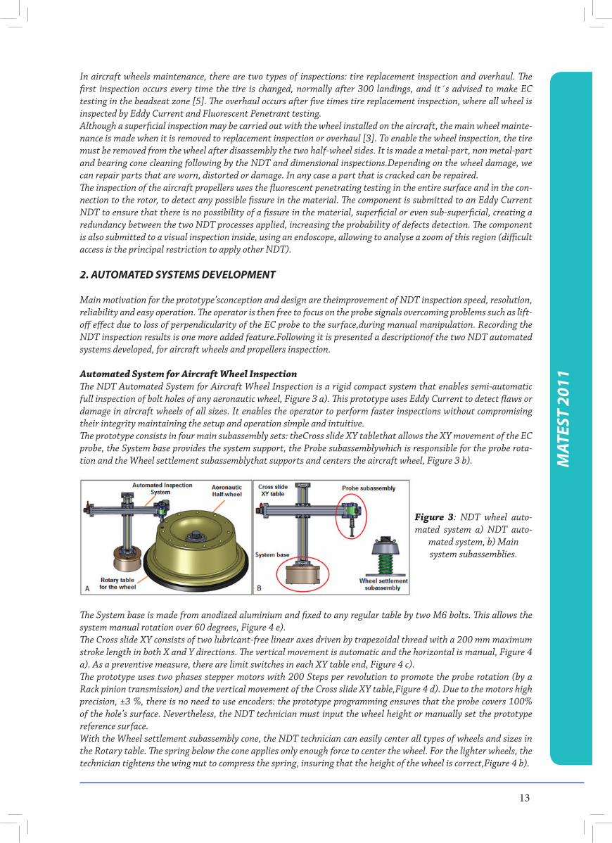
Automated System for Aircraft Wheel InspectionThe NDT Automated System for Aircraft Wheel Inspection is a rigid compact system that enables semi-automatic full inspection of bolt holes of any aeronautic wheel, Figure 3 a). This prototype uses Eddy Current to detect flaws or damage in aircraft wheels of all sizes. It enables the operator to perform faster inspections without compromising their integrity maintaining the setup and operation simple and intuitive. The prototype consists in four main subassembly sets: theCross slide XY tablethat allows the XY movement of the EC probe, the System base provides the system support, the Probe subassemblywhich is responsible for the probe rota-tion and the Wheel settlement subassemblythat supports and centers the aircraft wheel, Figure 3 b).
Figure 3: NDT wheel auto-mated system a) NDT auto-
mated system, b) Main system subassemblies.
The System base is made from anodized aluminium and fixed to any regular table by two M6 bolts. This allows the system manual rotation over 60 degrees, Figure 4 e).The Cross slide XY consists of two lubricant-free linear axes driven by trapezoidal thread with a 200 mm maximum stroke length in both X and Y directions. The vertical movement is automatic and the horizontal is manual, Figure 4 a). As a preventive measure, there are limit switches in each XY table end, Figure 4 c).The prototype uses two phases stepper motors with 200 Steps per revolution to promote the probe rotation (by a Rack pinion transmission) and the vertical movement of the Cross slide XY table,Figure 4 d). Due to the motors high precision, ±3 %, there is no need to use encoders: the prototype programming ensures that the probe covers 100% of the hole’s surface. Nevertheless, the NDT technician must input the wheel height or manually set the prototype reference surface.With the Wheel settlement subassembly cone, the NDT technician can easily center all types of wheels and sizes in the Rotary table. The spring below the cone applies only enough force to center the wheel. For the lighter wheels, the technician tightens the wing nut to compress the spring, insuring that the height of the wheel is correct,Figure 4 b).

14
MAT
EST
2011
The NDT technician places de half-wheel in the Wheel settlement subassemblyand manually aligns the hole probe with the bolt hole, so the prototype can do the remaining tasks automatically. In this prototype model, the technician has got to rotate manually the wheel in order to start the inspection of a different bolt hole.
Figure 4: Main character-istics of prototype a) and b) System different movements; c) Limit switches; d) EC probe transmission; e) Rotation of
the system base.
This system is currently being improved and extended to include several inspection styles and wheels zones (e.g. beadseat), to increase the inspection speed, to be able to use different NDT techniques, Eddy Current and Ultrasonic, in the same inspection and to use the patented Ionic probes. The unique modular design of this prototype allows the incorporation of these changes by only removing the Probe subassembly, while the system base and the Cross slide XY table remains the same.
Production of a test block half-wheel for testing the prototypeTypically, certified standard blocks are used for testing and calibrating NDT probes, nevertheless to evaluate an entire NDT system is usual to introduce defects similar to real ones in equal components. A known method is EDM notches, as used byU. Godbole, et al [2].To test and validate this particular prototype, several EDM notches were made in one aircraft half-wheel with 0,5 and 1 mm deep inside the bolt-holes. Before testing the prototype, a dye and fluorescent penetrant inspection was made to ensure that the only defects present were the ones introduced by EDM. In conclusion, Figure 5shows that for both visual inspections the only defects in the bolt-hole are the notches done by EDM.
Figure 5: Dye and fluorescent penetrant inspection of aircraft half-wheel test specimen a) Application of penetrant; b) EDM notch by dye penetrant testing; c) EDM notch by fluorescent penetrant testing.
Automated System for Aircraft Propellers InspectionThe NDT automated system for aircraft propeller inspection is a modular system that allows the inspection of the surface of this aeronautic component, by performing the automatic displacement of the probes, Figure 6 a). Consti-tuted by a structure made in Bosch Rexroth aluminium profile, two linear Cross slide XY table driven by belt, one Cross slide XY table driven by trapezoidal thread and a system with bearings where the aircraft propeller is fixed.

15
MAT
EST
2011
Figure 6: NDT propeller blades automated systema) System different movements; b) and c) coupling probes and
stepper motors.
The Rotation System, where the aircraft propeller is fixed, allows the rotation of the component in his centre line, Figure 7a) and b). This feature will be used to align the surface that is being inspected with the probe, to obtain the perpendicularity between those two. This will be achieved by a pair of arms that work as claws, with the forces being applied by three springs in each arm, Figure 7 c and d).
Figure 7: Main characteristics of prototype a) and b) Rotation System; c) and d) Alignment
arms.
3. CONTROL OF AUTOMATED SYSTEMS
Automated System for Aircraft Wheel InspectionThe prototype uses a controller CompactRIO from National Instruments in order to: i) control the stepper motors; ii) acquire the limit switches and iii) acquire the Nortec 500C signals. Figure 8 illustrates the system.
Figure 8: System connections
overview
16
MAT
EST
2011
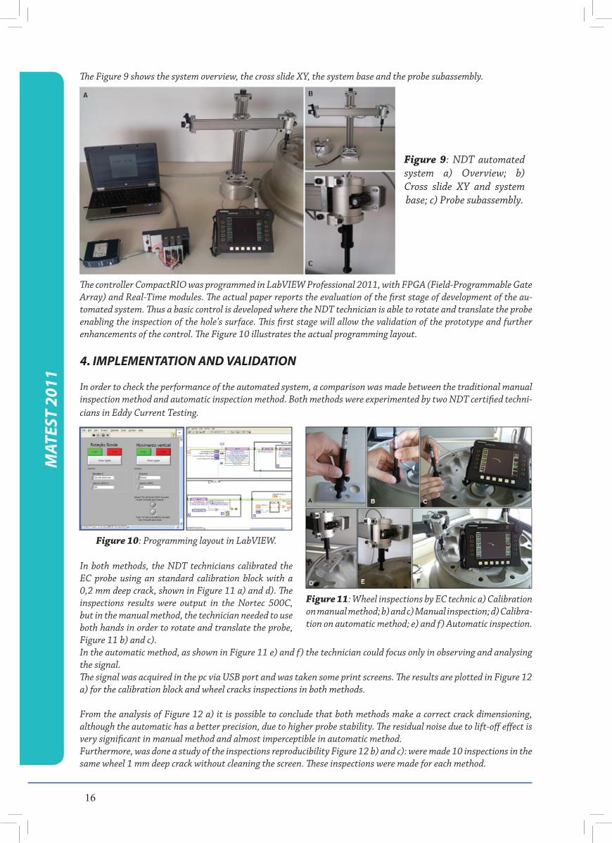
The Figure 9 shows the system overview, the cross slide XY, the system base and the probe subassembly.
Figure 9: NDT automated system a) Overview; b) Cross slide XY and system base; c) Probe subassembly.
The controller CompactRIO was programmed in LabVIEW Professional 2011, with FPGA (Field-Programmable Gate Array) and Real-Time modules. The actual paper reports the evaluation of the first stage of development of the au-tomated system. Thus a basic control is developed where the NDT technician is able to rotate and translate the probe enabling the inspection of the hole’s surface. This first stage will allow the validation of the prototype and further enhancements of the control. The Figure 10 illustrates the actual programming layout.
4. IMPLEMENTATION AND VALIDATION
In order to check the performance of the automated system, a comparison was made between the traditional manual inspection method and automatic inspection method. Both methods were experimented by two NDT certified techni-cians in Eddy Current Testing.
Figure 10: Programming layout in LabVIEW.
Figure 11: Wheel inspections by EC technic a) Calibration on manual method; b) and c) Manual inspection; d) Calibra-tion on automatic method; e) and f) Automatic inspection.
In both methods, the NDT technicians calibrated the EC probe using an standard calibration block with a 0,2 mm deep crack, shown in Figure 11 a) and d). The inspections results were output in the Nortec 500C, but in the manual method, the technician needed to use both hands in order to rotate and translate the probe, Figure 11 b) and c). In the automatic method, as shown in Figure 11 e) and f) the technician could focus only in observing and analysing the signal. The signal was acquired in the pc via USB port and was taken some print screens. The results are plotted in Figure 12 a) for the calibration block and wheel cracks inspections in both methods.
From the analysis of Figure 12 a) it is possible to conclude that both methods make a correct crack dimensioning, although the automatic has a better precision, due to higher probe stability. The residual noise due to lift-off effect is very significant in manual method and almost imperceptible in automatic method.Furthermore, was done a study of the inspections reproducibility Figure 12 b) and c): were made 10 inspections in the same wheel 1 mm deep crack without cleaning the screen. These inspections were made for each method.

17
From the analysis of Figure 12 b) and c) it is possible to conclude that automatic method is more reproducible com-pared to the manual one. In order to address the productivity impact of the developments, a graph showing the time need inspecting one half-wheel is presented in Figure 13. Notice the inspection time is composed by the assembly, inspection and disassembly time, in both methods.
Analysing Figure 13 it is possible to conclude that for a number of wheel holes to inspect higher than 3 the automatic method is more productive.
5. CONCLUSIONS
The main conclusions from the work are:• AnautomatedEddyCurrentTestingsystemforaircraftwheelwassuccessfullydeveloped.• Theprototypeallowstheautomaticcontroloftheverticaltranslationandproberotation.Thehorizontalpositioning is manual because the radial distance of several holes to the center of each wheel is typically constant.• TheECautomatedsystemdemonstratedthefollowingadvantages:
o In the case of a C130 aircraft half-wheel with 11 holes full inspection cycle, the time reduced was about 41% In general the productivity associated with the use of the automated system, increases with the number of wheel holes to be inspected;o Increasing the probe motion stability in the automatic system lead to better signal quality;o Increase the probe positioning accuracy and the inspection reproducibility;o Increase the inspection reliability by allowing the NDT technician to be dedicated exclusively to the NDT signal analysis;o Allows treating and storing the inspection result. With possibility to activate an automatic alarm to notify in case of detection of an imperfection above a certain threshold.
• Duetotheprobestability,wecaneliminatethesignalnoisethattypicallynotallowsthesmallimperfectionsdetection. By this, the threshold of detectability is lower in automatic method.• Whencomparedwiththemanualmethod,inwhichtheNDTtechnicianonlyhasgottocarrytheECequip-ment, one disadvantage of the prototype is his lower mobility.• Theprototypemodulardesignpresentsthefollowingadvantages:
o Possibility to inspect other wheel areas incorporating new probes, in particular beadseat and ventilati holes;o Easy to carry out automated system maintenance operations.
Figure 12: Inspection resultsa) Calibration block and wheel cracks inspections in both meth-ods; b) and c) Study of the in-
spection reproducibility
Figure 13: Graph of NDT inspections time for manual and
automatic method.
MAT
EST
2011
18
MAT
EST
2011
6. REFERENCES
1. T. G. Santos, P. Vilaça, R. M. Miranda, “Electrical conductivity fi eld analysis for evaluation of FSW joints in AA6013 and AA7075 alloys”. Journal of Materials Processing Technology. Volume 211, Issue 2, Pages 174-180. doi:10.1016/j.jmatprotec.2010.08.030. February 2011.2. GODBOLE, U., GOKHALE, A.; Eddy Current Inspection in Aircraft Industry; Proc. National Seminar on Non-Destructive Evaluation; 7 – 9 Dezembro 2006, Hyderabad; http://www.ndt.net/article/nde-india2006/fi les/tp-59-pap.pdf.3. KHAN, Md. AlahiUddin;Non-destructive Testing Applications in Commercial Aircraft Maintenance; 7th European Conference on Non-destructive Testing – ECNDT; 26-29 May 1998, Copenhaga; http://www.ndt.net/article/ecndt98/aero/031/031.htm.4. TurnKey NDT; VD3-71 universal eddy current fl aw detector application for fi eld inspection of aeronautical engineering;http://www.ndt.com.ua/en/articles/2_tools.html.5. CIVIL AVIATION AUTHORITY, U.K.; Civil Aircraft Inspection Procedure, Systems And Equipment – Wheels and Brakes – Chapter AL/3-19, 1973.6. KRAUSE, H.;HOHMANN, R.;GRüNEKLEE, M.; MAUS, M.; ZHANG, Y.; LOMPARSKI, D.; SOLTNER, H.; WOLF, W.; BANZET, M.; SCHUBERT, J.; ZANDER, W.; BOUSACK, H.; BRAGINSKI,A.I.;Aircraft Wheel and Fuse-lage Testing with Eddy Current and SQUID; 7th European Conference on Non-destructive Testing – ECNDT; 26-29 May 1998, Copenhaga; http://www.ndt.net/article/ecndt98/aero/043/043.htm.7. Luís Rosado, Telmo G. Santos, MoisésPiedade, Pedro Ramos, Pedro Vilaça, “Advanced technique for non-destructive testing of friction stir welding of metals”, Measurement (ISSN: 0263-2241), Volume 43, Issue 8, Pages 1021-1030. doi:10.1016/j.measurement.2010.02.006. 2010.8. LECLERC, Rémi, SAMSON, Rock; Eddy Current Array Probes for Aircraft Applications; 15th World Con-ference on Non-Destructive Testing; 15-21 October 2000, Rome;http://www.ndt.net/article/wcndt00/papers/idn514/idn514.htm.
AUTHORS wish to acknowledge to QREN - ADI via project “Aeroinspect”; contract n. 11518, co-supported by FEDER.