development of an ocs cementing operational …
TRANSCRIPT
DEVELOPMENT OF AN OCS CEMENTING OPERATIONAL GUIDELINES
DATABASE
A Thesis
by
MATTHEW GEORGE BELL
Submitted to the Office of Graduate and Professional Studies of
Texas A&M University
in partial fulfillment of the requirements for the degree of
MASTER OF SCIENCE
Chair of Committee, Jerome Schubert
Committee Members, Catalin Teodoriu
Yuefeng Sun
Head of Department, A. Daniel Hill
December 2014
Major Subject: Petroleum Engineering
Copyright 2014 Matthew George Bell
ii
ABSTRACT
This paper describes a relational database system developed for the Bureau of
Safety and Environmental Enforcement as part of an analysis of current cementing
procedures employed in the US outer continental shelf. Initial work included defining
the goals of the database, identifying its users, and selecting an appropriate database
management system. The main goal of the database is to present specific design, testing,
and operational procedures to ensure optimized cement seal effectiveness and to mitigate
potential safety issues. The database was planned and created in Microsoft Access for
engineering or regulatory users with special interests in outer continental shelf
cementing operations.
Initially, information was inputted into the database after an industry steering
committee identified and evaluated several wells in order to analyze the cementing
process and associated safety issues. Once the initial build was complete, functionality
was built into the database to collect information from industry experts. Simplistic, user-
friendly menu screens narrow down the database information to guidelines that are
pertinent to specific situations. The guidelines are then organized and presented in a
report format for easy interaction.
Recommendations of future work to maximize the effectiveness of the developed
database include making the menus and guidelines multilingual, modifying the reports to
properly display on mobile platforms, and expanding the guidelines to include other
areas in the petroleum industry.

iii
DEDICATION
This work is dedicated to my parents. My accomplishments would not be
possible without their unselfish dedication to providing for their children.
iv
ACKNOWLEDGEMENTS
I would like to thank my committee chair, Dr. Schubert, and my committee
members, Dr. Teodoriu and Dr. Sun for their guidance and support throughout the
course of this research.
A special thanks also goes to the entire staff at CSI Technologies for their
support, questions, concerns, and comments. I also want to extend my gratitude to the
Bureau of Safety and Environmental Enforcement (BSEE), which provided the funding
to complete this project.
I also acknowledge the various proprietary hardware and software referenced in
this paper. I have tried in good faith to identify all trademark names and formal owners:
Access and Excel are registered trademark of Microsoft Corp., FileMaker Pro is
registered trademark of Apple Computing Inc., and; ORACLE is a registered trademark
of Oracle Corp.
Finally, thanks to my mother, father, and brothers for their continuous
encouragement.
v
NOMENCLATURE
DBMS Database Management System
RDBMS Relational Database Management System
OODBMS Object Oriented Database Management System
OCS Outer Continental Shelf
BSEE Bureau of Safety and Environmental Enforcement
hp/ht High Pressure and High Temperature
SQL Structured Query Language
vi
TABLE OF CONTENTS
Page
ABSTRACT ....................................................................................................................... ii
DEDICATION ................................................................................................................. iii
ACKNOWLEDGEMENTS .............................................................................................. iv
NOMENCLATURE ........................................................................................................... v
TABLE OF CONTENTS .................................................................................................. vi
LIST OF FIGURES ........................................................................................................ viii
LIST OF TABLES ............................................................................................................. x
1. INTRODUCTION AND LITERATURE REVIEW .............................................. 1
1.1 Evolution of Databases in the Petroleum Industry ..................................... 1
1.1.1 Evolving Purpose ........................................................................... 1
1.1.2 Preparation ..................................................................................... 3
1.1.3 Hardware and Software .................................................................. 4
1.2 Database Management System Models .................................................... 10
1.2.1 Flat File Model ............................................................................. 10
1.2.2 Hierarchical and Network Models ............................................... 11
1.2.3 Relational Model .......................................................................... 14
1.2.4 Object-Oriented Model ................................................................ 15
1.3 Takeaway ................................................................................................. 16
2. OBJECTIVE AND PROCEDURE ...................................................................... 17
2.1 Objective .................................................................................................. 17
2.2 Procedure .................................................................................................. 17
2.2.1 Needs ............................................................................................ 18
2.2.2 End Users ..................................................................................... 18
2.2.3 Hardware and Software ................................................................ 19
2.2.4 Review with Industry Steering Committee .................................. 19
2.2.5 Writing the Program Code ........................................................... 19
3. RESULTS ............................................................................................................. 21
vii
4. CONCLUSIONS AND RECOMMENDATIONS ............................................... 31
4.1 Conclusions .............................................................................................. 31
4.2 Recommendations .................................................................................... 31
REFERENCES ................................................................................................................. 33
APPENDIX A – OIL BASED MUD DRILLING ........................................................... 39
APPENDIX B – WATER BASED MUD DRILLING .................................................... 42
APPENDIX C – SYNTHETIC BASED MUD DRILLING ............................................ 45
APPENDIX D – SEAFLOOR RETURNS INITIAL CASING PLACEMENT .............. 48
APPENDIX E – SURFACE RETURNS INITIAL CASING PLACEMENT ................. 56
APPENDIX F – INTERMEDIATE CASING PLACEMENT ........................................ 63
APPENDIX G – VERTICAL PRODUCTION CASING PLACEMENT ....................... 70
APPENDIX H – HORIZONTAL PRODUCTION CASING PLACEMENT ................. 77
APPENDIX I – TIEBACK CASING PLACEMENT ...................................................... 84
APPENDIX J – KICK-OFF REMEDIAL ....................................................................... 91
APPENDIX K – PLUG REMEDIAL .............................................................................. 94
APPENDIX L – SQUEEZE REMEDIAL ....................................................................... 97
APPENDIX M – PERFORATION REMEDIAL ............................................................ 99
viii
LIST OF FIGURES
Page
Figure 1 – IBM 360 with Optional Peripherals .................................................................. 5
Figure 2 – IBM 360 Deployed to NASA ........................................................................... 6
Figure 3 – IBM 3033 Mainframe ....................................................................................... 7
Figure 4 – IBM 5150 .......................................................................................................... 7
Figure 5 – MV-10000 ......................................................................................................... 8
Figure 6 – Compaq Portable ............................................................................................... 9
Figure 7 – Compaq Portable Packed Up ............................................................................ 9
Figure 8 – Schematic of a Flat File Database Management System ................................ 11
Figure 9 – Hierarchical Model Organization Example .................................................... 13
Figure 10 – Network Model Organization Example ........................................................ 13
Figure 11 – Schematic of a Relational Database Management System ........................... 15
Figure 12 – Menu Flow Diagram ..................................................................................... 22
Figure 13 – Introduction Menu ........................................................................................ 23
Figure 14 – Recommendation Entry Menu ...................................................................... 24
Figure 15 – Initial Consideration Menu ........................................................................... 25
Figure 16 – Mud Basis Menu ........................................................................................... 25
Figure 17 – Casing Purpose Menu ................................................................................... 26
Figure 18 – Returns Location Menu ................................................................................ 28
Figure 19 – Formation Consideration Menu .................................................................... 28

ix
Figure 20 – Casing Orientation Menu .............................................................................. 29
Figure 21 – Remedial Type Menu .................................................................................... 30
x
LIST OF TABLES
Page
Table 1 – Database Development Philosophy .................................................................... 3
Table 2 – Project Procedure ............................................................................................. 18

1
1. INTRODUCTION AND LITERATURE REVIEW
1.1 Evolution of Databases in the Petroleum Industry
Database development for the petroleum industry is very young compared to the
overall industry itself. While the first successful oil and gas well was drilled in 1859,
databases were not developed for the industry until the 1970’s (Maugeri 2006). Despite
the late start and much like many industries, databases have quickly become a necessary
and integral part of everyday operations. Today they are used for a variety of things from
storing and accessing information for research purposes to logging and storing
equipment maintenance schedules.
1.1.1 Evolving Purpose
The first databases systems adopted by the industry were brought on as an
upgrade of the previous computing systems to minimize their inconsistent results and
reduce the excessive time required to use these systems (Hatch and Block 1979, Hatch
and Miller 1983). Later as drilling activity increased to new heights, the simple
inefficiencies of people and established processes, such as submitting daily drilling
reports, were compounded and a need developed for more organized systems (Lacy and
Gill 1983). As microcomputers were introduced and adopted into the industry, systems
and software to compute and store simple calculations were sought (Zamora and Wilson
1986, Morton 1987).
2
At the same time as the introduction of calculation computing software for
microcomputers, the technology used in the drilling and completion portion of the
industry was also increasing greatly (Dunn and Payne 1986). With this increase in
technology came the increase in the information that needed to be collected during these
processes. As a result, this information was never completely analyzed until databases
were built to compute the repetitive calculations (Allison et al. 1988).
Once the computing storage capacity became robust enough to capture the
enormous amount of information from the field, databases were then tailored to the
optimization of processes and benchmarking (McCammon et al. 1993). These newer
databases allowed the engineers to meet the increasing demand for the more efficient use
of their time (Leach et al. 1994). In many cases, this was accomplished by moving from
using uncontrolled Microsoft Excel spreadsheets to using carefully compiled and
controlled databases in order to complete many of their job functions (Thomson and
Manifold 2000).
Today’s challenges being addressed by customized databases are the capture,
storage and fast navigation of different file types instead of only text based entries. Some
examples of these file types could be unique seismic files, simulation files, and images
of logging results (Tryhall and Martin 1992, Trythall 1994). Furthermore, as the initial
database systems become more and more dated, another problem being addressed today
is the migration of legacy data into new systems. The challenge to this is insuring that
the knowledge is preserved and can be used effectively in the new systems. (Barrett and
Kennelly 1994, Bougherara et al. 2013, Hanley et al. 2011) Finally, databases today are
3
advancing by being programed to be decision making systems through the application of
artificial Bayesian intelligence. (Al-Yami et al. 2010)
1.1.2 Preparation
Throughout the available literature, there has been one main methodology
followed when designing and building a database for use in the petroleum industry. This
procedure was first clearly outlined in 1986 by Zamora and Wilson and is shown in
Table 1.
Table 1 – Database Development Philosophy (Zamora and Wilson 1986)
1. Define Needs
2. Review Goals with Management
3. Identify the End Users
4. Write the User’s Manual
5. Evaluate Hardware / Software Options
6. Plan and Organize the Integrated Package
7. Write the Program Code
8. Monitor Progress and Revise Goals / Plans if Necessary
9. Test, Test, Test
10. Follow-Through and Follow-Up
Even though most database developers tweaked this method in one way or
another, the basic procedural structure remained the same. For instance, in some cases a
partial program would be rolled out to a test group while the software development was
still taking place (Corless 1991, Brannigan 1992). This was typically scheduled in either
4
a two or three phase implementation system. Doing this allowed developers to
implement suggestions into parts of the software that had not been delivered to the users
yet. While this software roll-out method still produced quality results, it caused a
significantly larger amount of updates to the system due to the lack of an explanation of
what was changing and why it was necessary. While the updates were typically less
substantial in the amount of the software that was affected, the need for systematic
updating procedures became apparent. (Opsahl and Loras 1994).
1.1.3 Hardware and Software
Since the first documented database instillation, there have been at least
seventeen cycles of Moore’s law (Moore 1965). As a result, vast advances in the
hardware and software that make-up the databases in the industry have taken place. In
1975, the first documented database to be installed for the petroleum industry consisted
of an IBM 360 system running software called the Mark IV File Management System
which was also known as Mark IV for short (Hatch and Block 1979). The Mark IV was
a pre-relational or flat file type of database management system.
The IBM 360 was a very historically important computing product. Commonly
referred to as IBM’s five billion dollar gamble, the IBM 360 carried a very steep price
tag between $250,000 to $12,500,000 (IBM Archives 2014). This was also the same
product line of computer that helped NASA land a person on the moon (Boyer 2004).
The Mark IV File Management Systems was also historically significant.
Depending on any additional special features, the price tag on the Mark IV ranges from
5
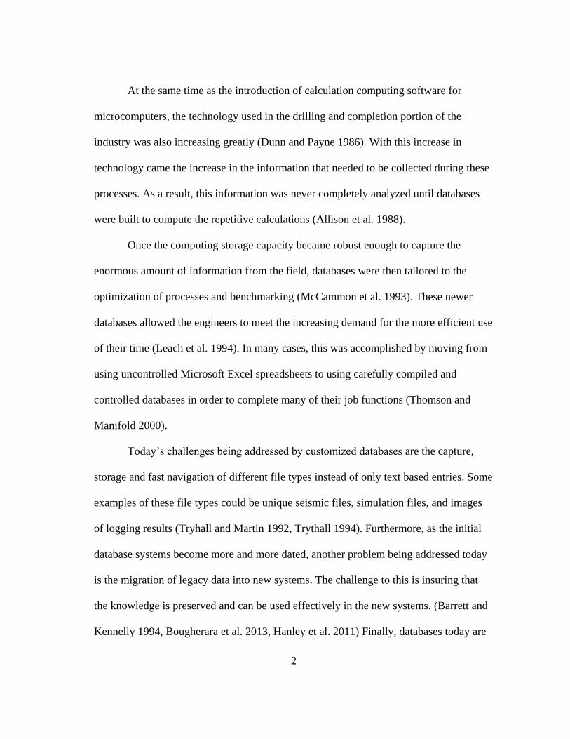
$30,000 to $160,000 (Postley 1998). Many historians consider that the Mark IV software
led to the birth of the software industry because it was with this software, that IBM
announced that it would stop giving away its software free along with its computers
(Hoch et al. 1999). Examples of the IBM 360 can be seen in Figures 1 and 2.
Figure 1 – IBM 360 with Optional Peripherals (Boyer 2004)
6
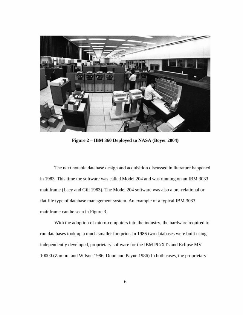
Figure 2 – IBM 360 Deployed to NASA (Boyer 2004)
The next notable database design and acquisition discussed in literature happened
in 1983. This time the software was called Model 204 and was running on an IBM 3033
mainframe (Lacy and Gill 1983). The Model 204 software was also a pre-relational or
flat file type of database management system. An example of a typical IBM 3033
mainframe can be seen in Figure 3.
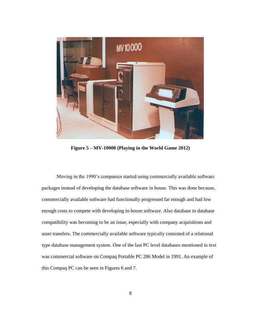
With the adoption of micro-computers into the industry, the hardware required to
run databases took up a much smaller footprint. In 1986 two databases were built using
independently developed, proprietary software for the IBM PC/XTs and Eclipse MV-
10000.(Zamora and Wilson 1986, Dunn and Payne 1986) In both cases, the proprietary

7
software developed was a relational type database management system. Examples of the
IBM PC/XT and Eclipse MV-10000 can be seen in Figures 4 and 5 respectively.
Figure 3 – IBM 3033 Mainframe (IBM Archives 2014)
Figure 4 – IBM 5150 (Stengel 2013)
8
Figure 5 – MV-10000 (Playing in the World Game 2012)
Moving in the 1990’s companies started using commercially available software
packages instead of developing the database software in house. This was done because,
commercially available software had functionally progressed far enough and had low
enough costs to compete with developing in-house software. Also database to database
compatibility was becoming to be an issue, especially with company acquisitions and
asset transfers. The commercially available software typically consisted of a relational
type database management system. One of the last PC level databases mentioned in text
was commercial software on Compaq Portable PC 286 Model in 1991. An example of
this Compaq PC can be seen in Figures 6 and 7.

9
Figure 6 – Compaq Portable (Stengel 2013)
Figure 7 – Compaq Portable Packed Up (Stengel 2013)
After the early 1990’s, the networking technology that was adopted into the
industry had functionally progressed enough that the majority of databases were installed
on server level systems. The software used on these systems was almost exclusively
commercially available database management systems (DBMS). Unless under special
circumstances, the commercially available software used was a relational database
management system (RDBMS) (Bourgoyne et al. 1994, Jefferson et al. 1996, Thompson
2003).
10
1.2 Database Management System Models
Databases are typically categorized into several different modeling types. When
designing a database, choosing the correct model for the application is typically a
decision to be made fairly early on in the planning process. The following subsections
explain several of the model types previously mentioned.
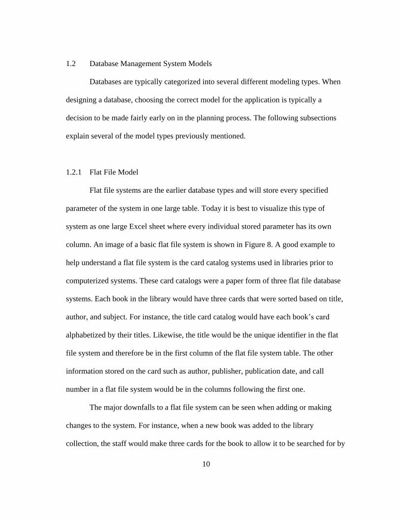
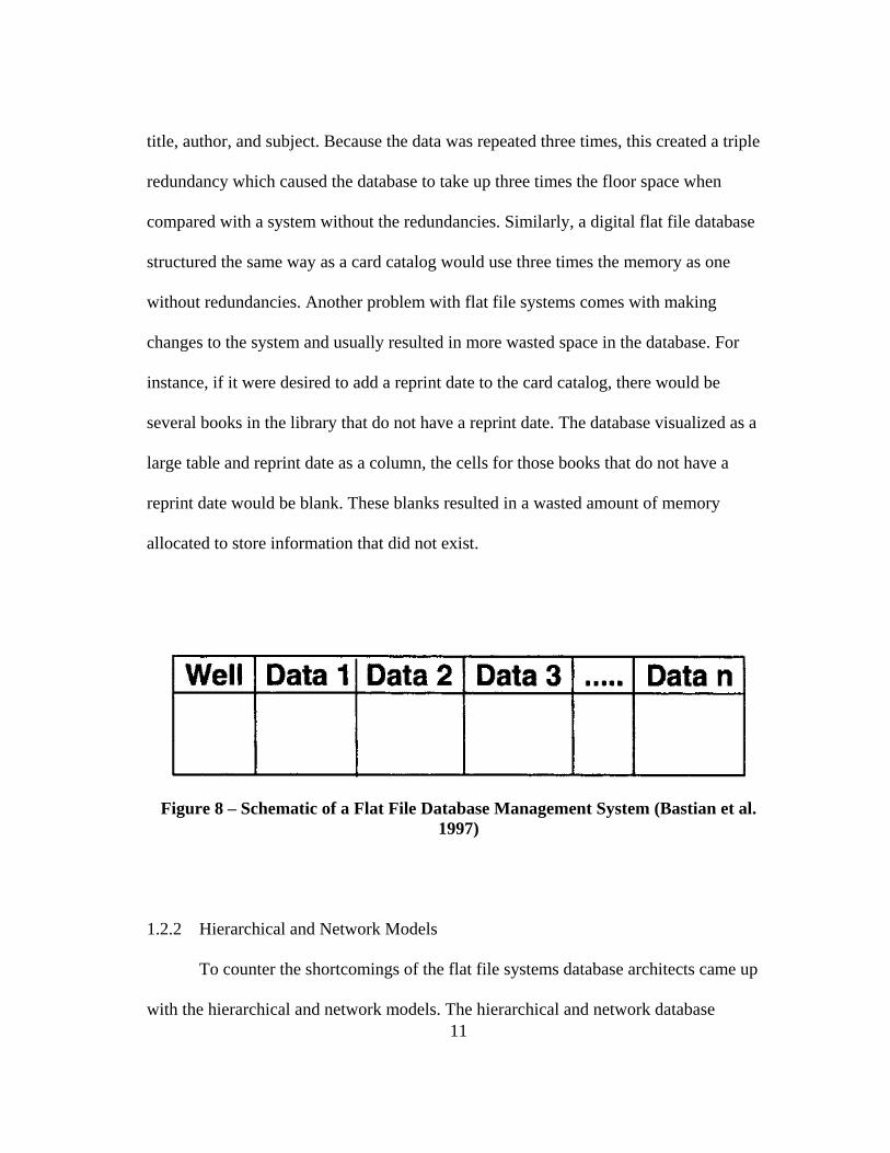
1.2.1 Flat File Model
Flat file systems are the earlier database types and will store every specified
parameter of the system in one large table. Today it is best to visualize this type of
system as one large Excel sheet where every individual stored parameter has its own
column. An image of a basic flat file system is shown in Figure 8. A good example to
help understand a flat file system is the card catalog systems used in libraries prior to
computerized systems. These card catalogs were a paper form of three flat file database
systems. Each book in the library would have three cards that were sorted based on title,
author, and subject. For instance, the title card catalog would have each book’s card
alphabetized by their titles. Likewise, the title would be the unique identifier in the flat
file system and therefore be in the first column of the flat file system table. The other
information stored on the card such as author, publisher, publication date, and call
number in a flat file system would be in the columns following the first one.
The major downfalls to a flat file system can be seen when adding or making
changes to the system. For instance, when a new book was added to the library
collection, the staff would make three cards for the book to allow it to be searched for by
11
title, author, and subject. Because the data was repeated three times, this created a triple
redundancy which caused the database to take up three times the floor space when
compared with a system without the redundancies. Similarly, a digital flat file database
structured the same way as a card catalog would use three times the memory as one
without redundancies. Another problem with flat file systems comes with making
changes to the system and usually resulted in more wasted space in the database. For
instance, if it were desired to add a reprint date to the card catalog, there would be
several books in the library that do not have a reprint date. The database visualized as a
large table and reprint date as a column, the cells for those books that do not have a
reprint date would be blank. These blanks resulted in a wasted amount of memory
allocated to store information that did not exist.
Figure 8 – Schematic of a Flat File Database Management System (Bastian et al.
1997)
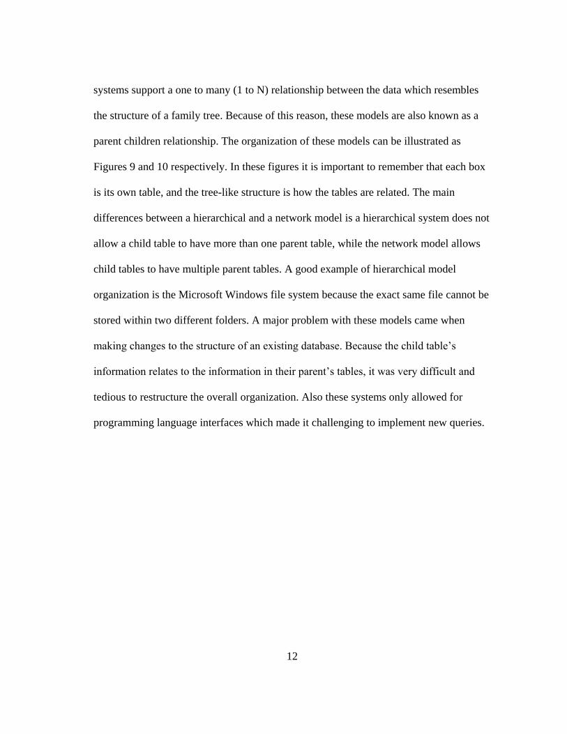
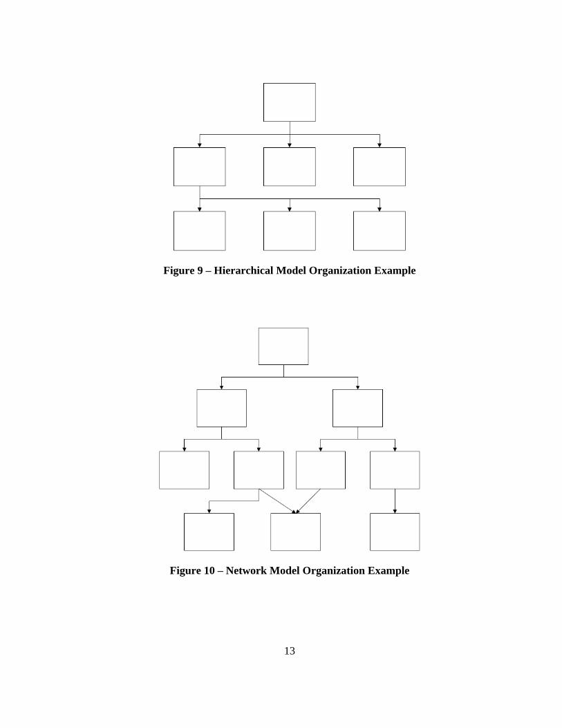
1.2.2 Hierarchical and Network Models
To counter the shortcomings of the flat file systems database architects came up
with the hierarchical and network models. The hierarchical and network database
12
systems support a one to many (1 to N) relationship between the data which resembles
the structure of a family tree. Because of this reason, these models are also known as a
parent children relationship. The organization of these models can be illustrated as
Figures 9 and 10 respectively. In these figures it is important to remember that each box
is its own table, and the tree-like structure is how the tables are related. The main
differences between a hierarchical and a network model is a hierarchical system does not
allow a child table to have more than one parent table, while the network model allows
child tables to have multiple parent tables. A good example of hierarchical model
organization is the Microsoft Windows file system because the exact same file cannot be
stored within two different folders. A major problem with these models came when
making changes to the structure of an existing database. Because the child table’s
information relates to the information in their parent’s tables, it was very difficult and
tedious to restructure the overall organization. Also these systems only allowed for
programming language interfaces which made it challenging to implement new queries.
13
Figure 9 – Hierarchical Model Organization Example
Figure 10 – Network Model Organization Example

14
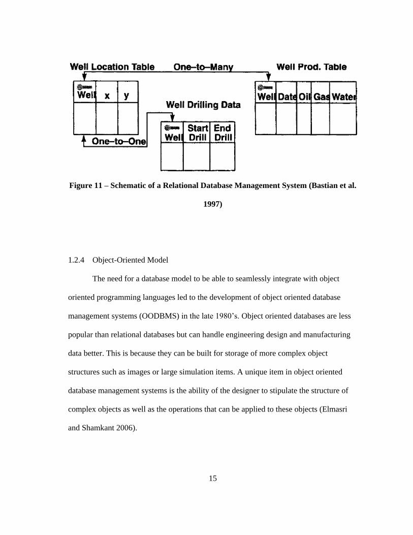
1.2.3 Relational Model
Relational databases were first developed in early 1970’s and were proposed to
allow for the separation of the physical data storage from the end user’s terminals and to
give a mathematical foundation for databases (Codd 1970). Relational databases also
introduced a high level query language which displaced the programming language
interfaces from the hierarchical and network models. These new languages allowed
queries to be developed more quickly and are known today as structured query language
(SQL). Although being very slow when they first were being implemented, the advances
in data storage and better query processing have allowed relational databases to become
the most common model used today. (Elmasri and Shamkant 2006)
The relational model gets its name from the way that tables can be linked or
related together. In a typical relational based database, anytime new data is added to a
table, the system will give it a unique identifier which is also known as a primary key.
This primary key is then utilized to identify which data needs to be accessed or changed
and to relate rows of data together in different tables.
Figure 11 shows the breakout of a relational database into its various tables and
primary keys. Organizing in this way allows for less unintended redundancies, less
wasted memory, as well as easier long term design flexibility (Borthne et al. 1996).
15
Figure 11 – Schematic of a Relational Database Management System (Bastian et al.
1997)
1.2.4 Object-Oriented Model
The need for a database model to be able to seamlessly integrate with object
oriented programming languages led to the development of object oriented database
management systems (OODBMS) in the late 1980’s. Object oriented databases are less
popular than relational databases but can handle engineering design and manufacturing
data better. This is because they can be built for storage of more complex object
structures such as images or large simulation items. A unique item in object oriented
database management systems is the ability of the designer to stipulate the structure of
complex objects as well as the operations that can be applied to these objects (Elmasri
and Shamkant 2006).
16
1.3 Takeaway
The use of databases in the petroleum industry as well as the hardware and
software that make them up have changed significantly throughout its short lifespan.
Initially databases were used solely for storage and quick retrieval of information but
were quickly shifted to focus on streamlining drilling operations. When computing
processing power became capable and networking technologies were developed and
standardized, databases started to host applications for computational analysis tools as
well. Most recently, there has been an increase in designing databases for storing
industry mandates and requirements for various activities. While the models of DBMS
have changed, today the majority of systems are based on the relational model. In the
end, the overall goal of most databases is simply to improve the efficiency of the
employees.
Two cases in literature present databases being developed for purposes very
similar to documenting operational guidelines. First, a lessons learned database was
developed in 2000 and the second was a safety and environmental standards database
developed in 2003.(Dewhirst et al. 2000, Thompson 2003) As far as the author knows,
there has not been a documented case of an operational guidelines database being
developed.
17
2. OBJECTIVE AND PROCEDURE
2.1 Objective
The objective of this study was to build a database that best represents the
findings of a BSEE funded project evaluating current cementing procedures used in US
OCS. First evaluations of various programming languages and database development
software were completed in order to determine which were the best suited for this
application. Once this was done, the database was built with a user interface that will not
require any training to take full advantage of the software. This software intended to help
achieve the overall presentation of recommended guidelines in an interactive way that
supported the use of these guidelines and also allowed for easy revisions or additions to
the information.
2.2 Procedure
The procedure used to build this database was a modified version of the Zamora
and Wilson’s philosophy previously mentioned in the literature review. Table 2 shows
the modified version that was followed for this application.

18
Table 2 – Project Procedure
1. Define Needs
2. Identify the End Users
3. Evaluate Hardware / Software Options
4. Review Needs, Identified Users, and Hardware and Software
Recommendation with Steering Committee
5. Write the Program Code
6. Submit for Testing
7. Make Corrections
8. Submit Final Database
2.2.1 Needs
As an important tool, the database’s goal was be a living software, this means
that it must be very easy to change when new recommendations were available and was
also very easy to adopt the structure to other oil and gas operations such as plugging and
abandonment or well intervention. In order to achieve this goal, it needed to be
programmed with a common language that was compatible with popular industry
systems. Above all, the system must be extremely user friendly with a user interface that
does not require training to operate.
2.2.2 End Users
The expected users of this system were expected to be engineering or regulatory
staff, knowledgeable with basic computer navigation. In this instance of the software, the
users would be seeking to find recommended OCS cementing operational guidelines.

19
2.2.3 Hardware and Software
Based on the needs and end users, a relational model database was the best
option because the operational guidelines are typically text based. Using an object
oriented type database would have ended up being a mismatched system for what was
being stored in the database. At this point in the process, common RDBMS were
identified based on their popularity and ability to adhere to the needs of the project. In
the end, three software options were identified as the most viable options. These were
FileMaker Pro, Microsoft Access, and MySQL. It was recommended to use Microsoft
Access because it is likely the most common DBMS due to its availability with the
Microsoft Office Suite.
2.2.4 Review with Industry Steering Committee
The steering committee agreed with the overall goals, potential end users and
recommended software for the database. Additional input was added that in order to
achieve the ultimate goal of user friendliness, there should not have been a large number
of overly complicated questions in order to narrow down the operational guidelines to a
specific purpose. Having this type of system would affect a person’s ability to
repetitively use to software and produce the same results.
2.2.5 Writing the Program Code
Over the course of a three month period, the database and user interface was
constructed with Microsoft Access. After the initial construction, the database went

20
through a month long testing period. After this, processing and implementing the
corrections and suggestions to the database took a month. The final user interface and
overall layout of the database is presented in the results section to follow.
21
3. RESULTS
The cementing operational guidelines reported in the database are a result of the
other tasks in the BSEE funded project. They are based on literature, field experiences
from an industry steering committee, and lab experiences from an energy services
company. The processes by with these results were obtained are not possible to mention
in detail in this paper. However, Appendices A through M show the results of the project
as the database divided and reported on them.
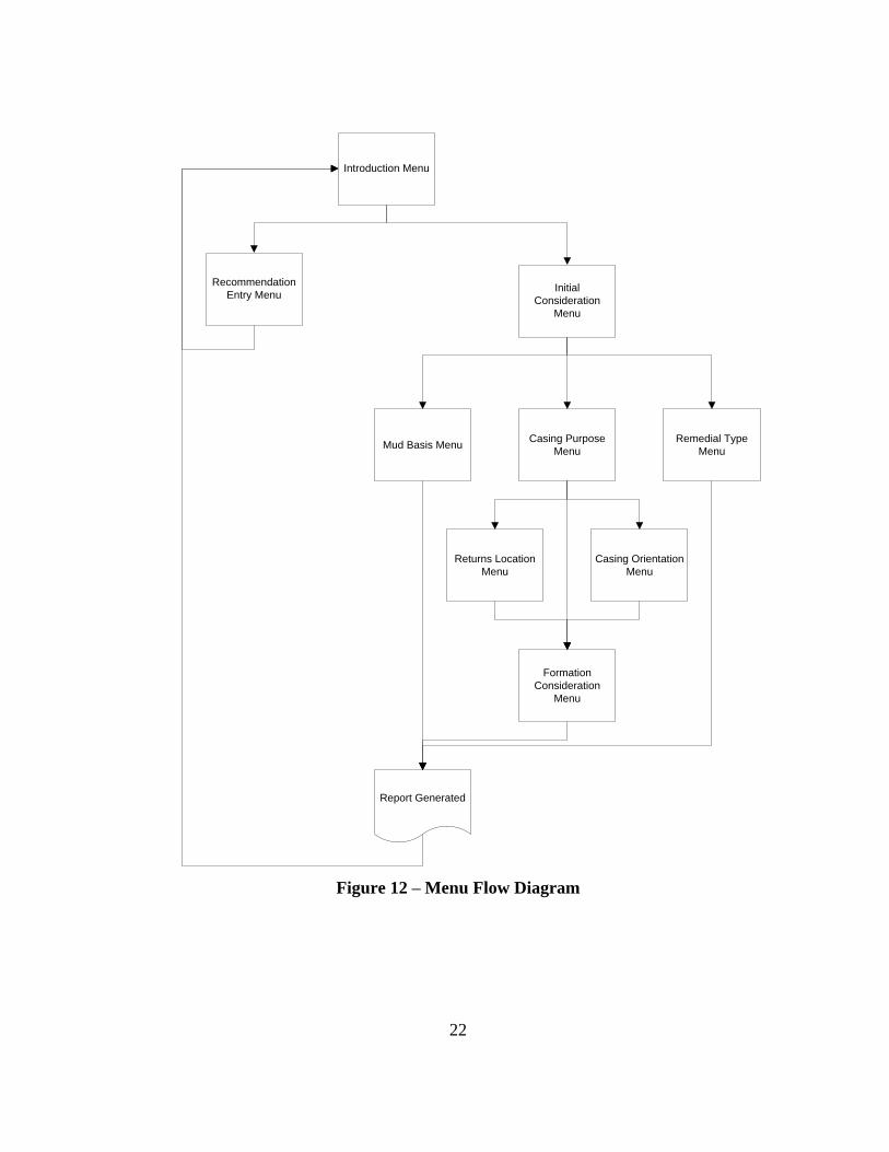
The user interface of the database consists of nine decision prompt menus that
are used to narrow down the operational guidelines to a general purpose, making it easier
for the user to receive only the information needed. Figure 12 shows the overall menu
flow diagram. When the user reaches the end of the decision menus, a report is generated
from the database and then displayed on screen. This report can then be saved as a
variety of file types or could be printed to a variety of page sizes. The majority of the
different reports that can be generated from the software are shown in Appendices A
through M.
22
Introduction Menu
Recommendation
Entry MenuInitial
Consideration
Menu
Mud Basis MenuCasing Purpose
Menu
Returns Location
Menu
Formation
Consideration
Menu
Casing Orientation
Menu
Remedial Type
Menu
Report Generated
Figure 12 – Menu Flow Diagram

23
The Operation Guidelines Database and Research Recommendation Platform
opens with the Introduction Menu shown in Figure 13. If Write Recommendation is
selected, then the Recommendation Entry Menu is shown in Figure 14. Any
recommendations for this database can be inputted through this menu. These
recommendations are then stored in a separate table of the relational database. The
database administrator can then look through the recommendations and anything to be
added to the operational guidelines could easily done from there.
Figure 13 – Introduction Menu

24
Figure 14 – Recommendation Entry Menu
If Continue is selected from the menu shown in Figure 13, then the following
series of menus appear and build an operation guidelines report around the selections.
The first menu to appear next would be the Initial Considerations Menu shown in Figure
15. This menu is the first menu to narrow down the operational guidelines to a specific
purpose. The user can choose from seeking either drilling, placement, or remedial
operational guidelines.
If the Drilling option is selected, the next menu to appear is the Mud Basis Menu
as shown in Figure 16. In this menu, the user can either choose from seeking operational
guidelines from oil, water, or synthetic based muds in the drilling operations. After this

25
screen, the report is generated with the operational guidelines narrowed based on the
decision of the options in Figure 16. If Oil Based Mud is selected the report generated is
shown in Appendix A. Likewise, if Water Based Mud or Synthetic Based Mud is
selected, then the reports generated are shown in Appendix B and Appendix C
respectively.
Figure 15 – Initial Consideration Menu
Figure 16 – Mud Basis Menu
26
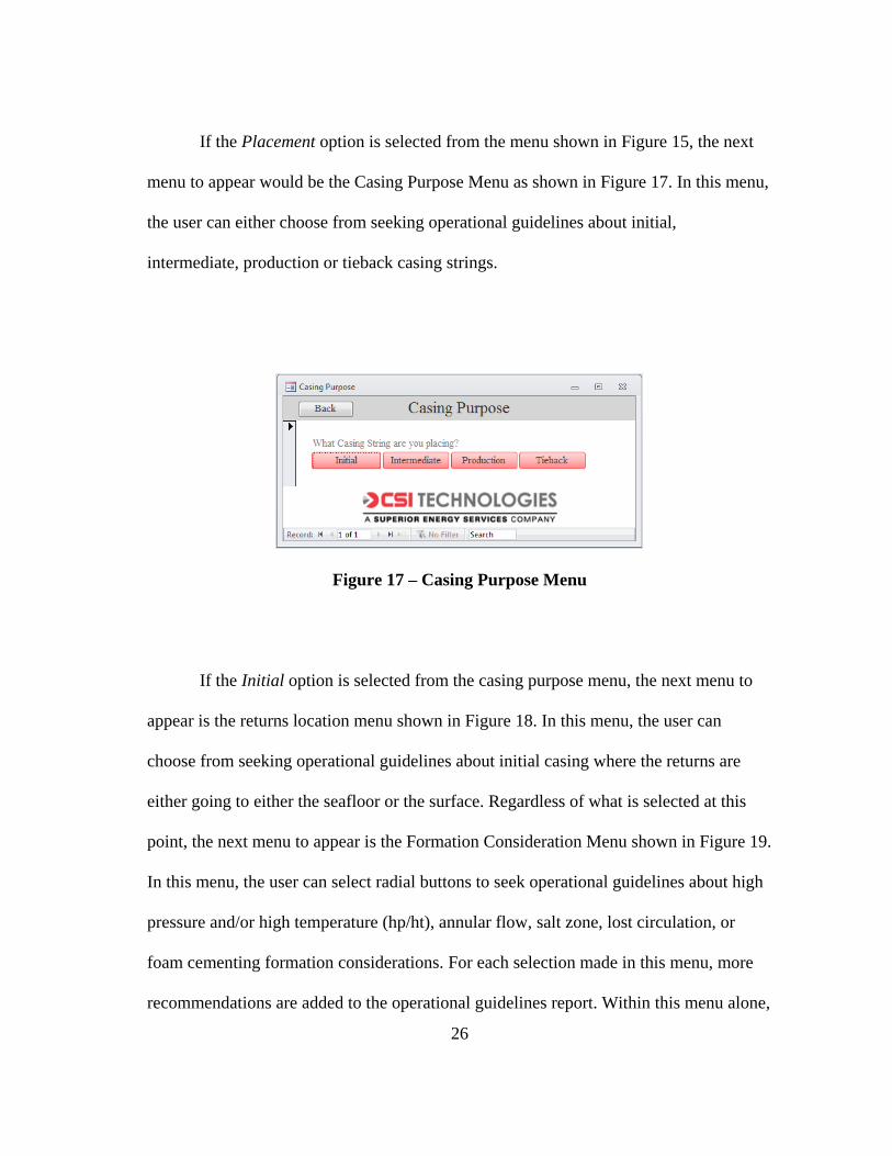
If the Placement option is selected from the menu shown in Figure 15, the next
menu to appear would be the Casing Purpose Menu as shown in Figure 17. In this menu,
the user can either choose from seeking operational guidelines about initial,
intermediate, production or tieback casing strings.
Figure 17 – Casing Purpose Menu
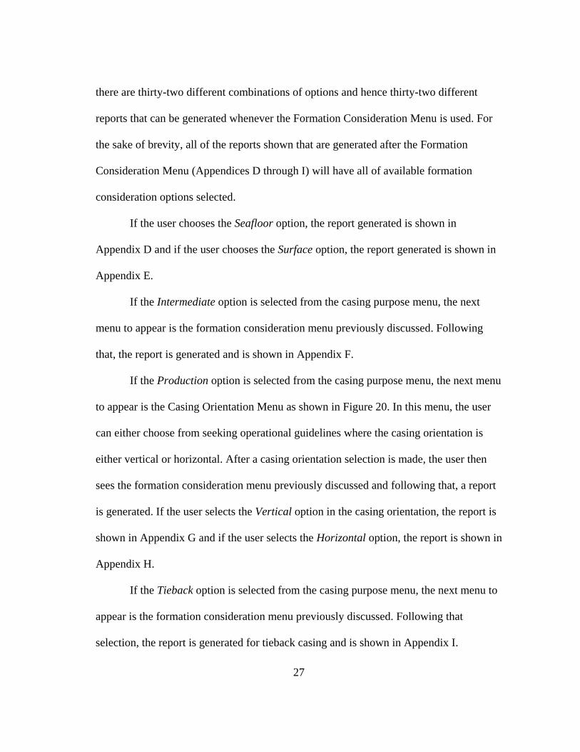
If the Initial option is selected from the casing purpose menu, the next menu to
appear is the returns location menu shown in Figure 18. In this menu, the user can
choose from seeking operational guidelines about initial casing where the returns are
either going to either the seafloor or the surface. Regardless of what is selected at this
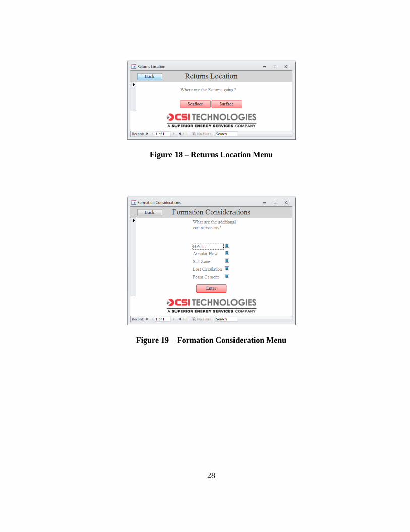
point, the next menu to appear is the Formation Consideration Menu shown in Figure 19.
In this menu, the user can select radial buttons to seek operational guidelines about high
pressure and/or high temperature (hp/ht), annular flow, salt zone, lost circulation, or
foam cementing formation considerations. For each selection made in this menu, more
recommendations are added to the operational guidelines report. Within this menu alone,
27
there are thirty-two different combinations of options and hence thirty-two different
reports that can be generated whenever the Formation Consideration Menu is used. For
the sake of brevity, all of the reports shown that are generated after the Formation
Consideration Menu (Appendices D through I) will have all of available formation
consideration options selected.
If the user chooses the Seafloor option, the report generated is shown in
Appendix D and if the user chooses the Surface option, the report generated is shown in
Appendix E.
If the Intermediate option is selected from the casing purpose menu, the next
menu to appear is the formation consideration menu previously discussed. Following
that, the report is generated and is shown in Appendix F.
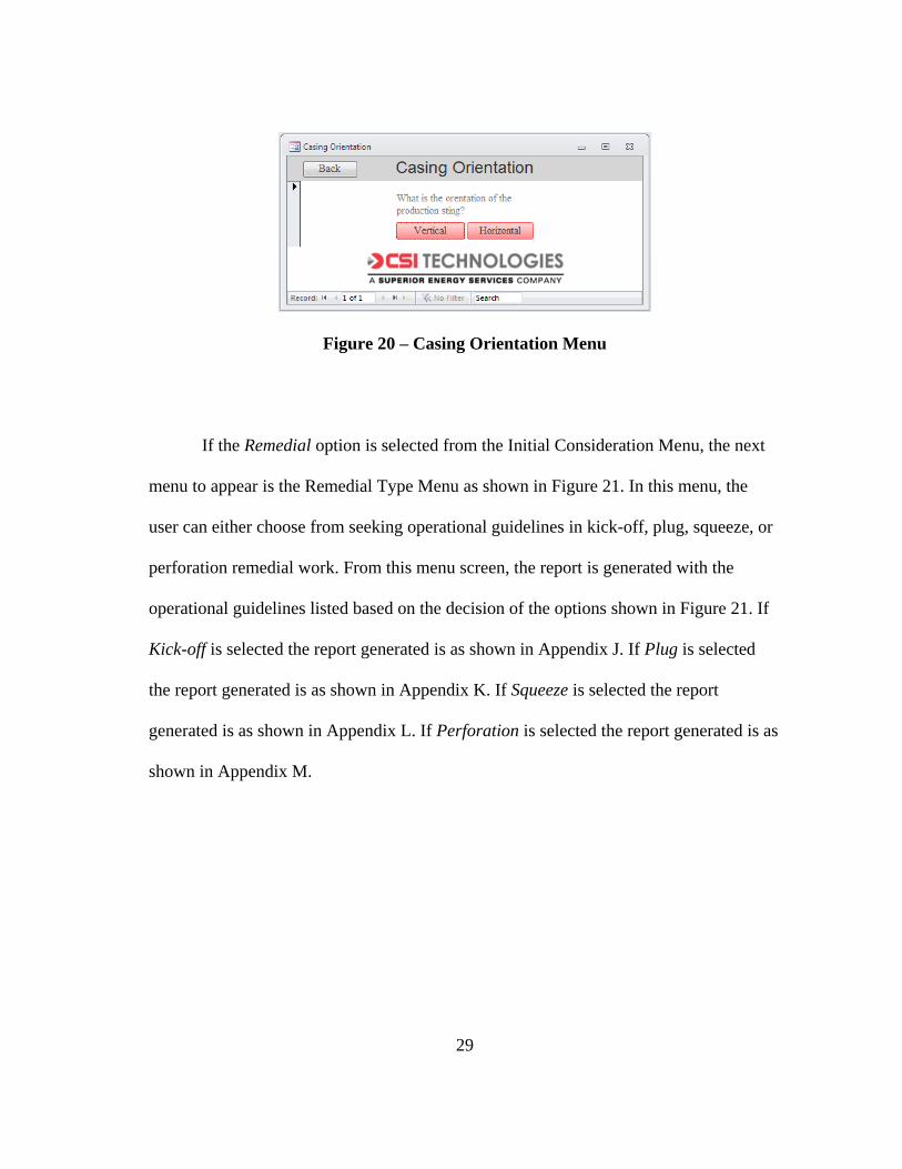
If the Production option is selected from the casing purpose menu, the next menu
to appear is the Casing Orientation Menu as shown in Figure 20. In this menu, the user
can either choose from seeking operational guidelines where the casing orientation is
either vertical or horizontal. After a casing orientation selection is made, the user then
sees the formation consideration menu previously discussed and following that, a report
is generated. If the user selects the Vertical option in the casing orientation, the report is
shown in Appendix G and if the user selects the Horizontal option, the report is shown in
Appendix H.
If the Tieback option is selected from the casing purpose menu, the next menu to
appear is the formation consideration menu previously discussed. Following that
selection, the report is generated for tieback casing and is shown in Appendix I.
28
Figure 18 – Returns Location Menu
Figure 19 – Formation Consideration Menu
29
Figure 20 – Casing Orientation Menu
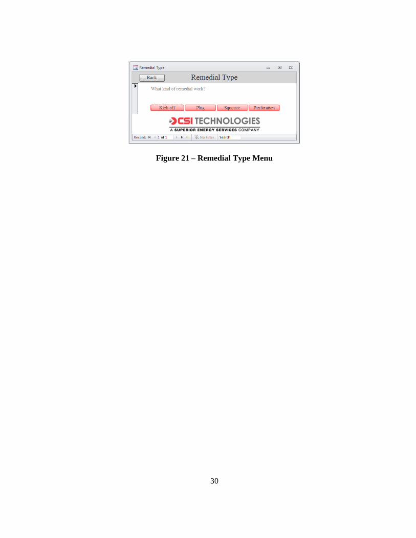
If the Remedial option is selected from the Initial Consideration Menu, the next
menu to appear is the Remedial Type Menu as shown in Figure 21. In this menu, the
user can either choose from seeking operational guidelines in kick-off, plug, squeeze, or
perforation remedial work. From this menu screen, the report is generated with the
operational guidelines listed based on the decision of the options shown in Figure 21. If
Kick-off is selected the report generated is as shown in Appendix J. If Plug is selected
the report generated is as shown in Appendix K. If Squeeze is selected the report
generated is as shown in Appendix L. If Perforation is selected the report generated is as
shown in Appendix M.
30
Figure 21 – Remedial Type Menu

31
4. CONCLUSIONS AND RECOMMENDATIONS
4.1 Conclusions
1. The OCS cementing operational guidelines database was successfully developed
and accomplished the objectives defined in the original proposal including the
detailed needs, end user requirements, and hardware and software requirements.
2. This operational guidelines database provides a means of quickly narrowing
down sets of operation guidelines to deliver only what was pertinent to the user’s
current situation.
3. The ability to deliver information on particular situations with which the end user
does not possess any experience and familiarity with, extends the experience of
all contributing users accessing the database.
4.2 Recommendations
The following are recommendations that would to maximize the effectiveness of
this database:
1. Translate the menus and operational guidelines into other languages that would
promote it use worldwide.
2. Adopt the database to function using asp.net coding to enable it to be hosted on
the World Wide Web.
3. Adopt the database to function correctly when accessed from the variety of
mobile platforms.

32
4. Expand the operational guidelines to other popular oil and gas industry areas
such as well control, coiled tubing drilling, and plug and abandonment.
33
REFERENCES
Al-Yami, A. S., Schubert, J., Medina-Cetina, Z. et al. 2010. Development of A Drilling
Expert System for Designing and Applying Successful Cement Jobs. Paper SPE
135183 presented at the IADC/SPE Asia Pacific Drilling Technology Conference
and Exhibition, Ho Chi Minh City, Vietnam, 1 - 3 November.
http://dx.doi.org/10.2118/135183-MS
Allison, J. L., Rezvani, M., and Leake, R. E. 1988. Time and Cost Reductions Through a
Database-Designed Directonal Drilling Program. Paper SPE 17218 presented at
the 1988 IADC/SPE Drilling Conference, Dallas, Texas, 28 February - 2 March.
http://dx.doi.org/10.2118/17218-MS
IBM Archives. 2014. 3033 Reference Room, http://www-
03.ibm.com/ibm/history/exhibits/3033/3033_album.html (accessed 31 May
2014).
IBM Archives. 2014. System 360: Model 44, http://www-
03.ibm.com/ibm/history/exhibits/mainframe/mainframe_PP2044.html (accessed
31 May 2014).
IBM Archives. 2014. System 360: Model 195, http://www-
03.ibm.com/ibm/history/exhibits/mainframe/mainframe_PP2195.html (accessed
31 May 2014).
Barrett, T., and Kennelly, M. 1994. Migrating Legacy Applications to Object-Oriented
Frameworks. Paper SPE 27557 presented at the European Petroleum Computer
34
Conference, Aberdeen, U.K., 15 - 17 March. http://dx.doi.org/10.2118/27557-
MS
Bastian, P. A., Pietsch, C. L., and Voneiff, G. W. 1997. Solving Engineering Problems
with PC-Based Relational Databases. SPE Computer Applications 9 (5): 136 -
140. SPE-38119-PA. http://dx.doi.org/10.2118/38119-PA.
Borthne, G., Johannessen, O., and Hedne, P. 1996. Modeling and Implementation of a
Database for Multiphase Flow Experiments. Paper SPE 35996 presented at the
SPE Petroleum Computer Conference, Dallas, Texas, 2 - 5 June.
http://dx.doi.org/10.2118/35996-ms
Bougherara, N. E., Morsli, S. A., Sali, S. et al. 2013. Creation of a National Database
from Multiple Legacy Data Sources. Paper SPE 165827 presented at the SPE
Asia Pacific Oil & Gas Conference and Exhibition, Jakarta, Indonesia, 22 - 24
October. http://dx.doi.org/10.2118/165827-MS
Bourgoyne, A. T., Sinha, V. K., and Rocha, L. A. 1994. General Access Well
Information Database. Paper SPE 28232 presented at the SPE Petroleum
Computer Conference, Dallas, Texas, 31 July - 3 August.
http://dx.doi.org/10.2118/28232-MS
Boyer, C. 2004. System 360: From Computers to Computer Systems, http://www-
03.ibm.com/ibm/history/ibm100/us/en/icons/system360/transform/ (accessed 31
May 2014).
Brannigan, J. C. 1992. The Characterization of Drilling Operations and Their
Representation in Relational Databases. Paper SPE 24429 presented at the
35
Seventh SPE Petroleum Computer Conference, Houston, Texas, 19 - 22 July.
http://dx.doi.org/10.2118/24429-MS
Codd, E. F. 1970. A Relational Model of Data for Large Shared Data Banks. Commun.
ACM 13 (6): 377-387. http://dx.doi.org/10.1145/362384.362685.
Corless, S. 1991. Implementation of a Drilling Database System. Paper SPE 23016
presented at the SPE Asia-Pacific Conference, Perth, Western Australia, 4 - 7
November. http://dx.doi.org/10.2118/23016-MS
Dewhirst, N. W., Evans, D. C., Chalfont, S. et al. 2000. Development of an Active
Global Lessons Learned Database - LINK. Paper SPE 64529 presented at the
SPE Asia Pacific Oil and Gas Conference and Exhibition, Brisbane, Australia, 16
- 18 October 2000. http://dx.doi.org/10.2118/64529-MS
Dunn, M. D., and Payne, M. L. 1986. Design, Specification, and Implementation of
Drilling Operations Database Program. Paper SPE 15360 presented at the 61st
Annual Technical Conference and Exhibition, New Orleans, Louisiana, 5 - 8
October. http://dx.doi.org/10.2118/15360-MS
Elmasri, R., and Shamkant, N. 2006. Fundamentals of Database Systems, Fourth edition.
Boston, Massachusetts, Pearson Education, Inc.
Playing in the World Game. 2012. Hannover, 1983.
http://playingintheworldgame.files.wordpress.com/2012/10/cebit1.jpg (accessed
31 May 2014).
Hanley, C., Kubicki, J., Lumpkin, M. et al. 2011. Development of a Global Drilling
Performance Database. Paper SPE 148432 presented at the SPE/IADC Middle
36
East Drilling Technology Conference and Exhibition, Muscat, Oman, 24 - 26
October. http://dx.doi.org/10.2118/148432-MS
Hatch, D. G., and Block, W. E. 1979. Well Database System: Structure and Retrieval
Applications. Paper SPE 7759 presented at the Middle East Oil Technical
Conference, Manama, Bahrain, 25 - 29 March. http://dx.doi.org/10.2118/7759-
MS
Hatch, D. G., and Miller, E. L. 1983. Computer Well Database - An Engineer's Tool.
Paper SPE 11445 presented at the Middle East Oil Technical Conferernce,
Manama, Bahrain, 14 - 17 March. http://dx.doi.org/10.2118/11445-MS
Hoch, D. J., Roeding, C. R., Purkert, G. et al. 1999. Secrets of Software Success :
Management Insights from 100 Software Firms Around the World. Boston,
Massachusetts, Harvard Business School Press.
Jefferson, L. L., Nighswander, J. A., and Chang-Yen, D. A. 1996. A Scaleable, Database
Architecture for Storage of PVT Data. Paper SPE 35988 presented at the SPE
Petroleum Computer Conference, Dallas, Texas, 2 - 5 June.
http://dx.doi.org/10.2118/35988-pa
Lacy, K. D., and Gill, B. B. 1983. A Computer Database System Designed for Drilling
Information Analysis. Paper SPE 12073 presented at the 58th Annual Technical
Conference and Exhibition, San Francisco, California, 5 - 8 October.
http://dx.doi.org/10.2118/12073-MS

37
Leach, B. F., Scherer, P. W., and Starley, G. P. 1994. An Object-Oriented Approach to
Simulator Postprocessing. SPE Computer Applications 6 (4): 13 - 19. SPE-
26223-PA. http://dx.doi.org/10.2118/26223-pa.
Maugeri, L. 2006. The Age of Oil: The Mythology, History, and Future of the World's
Most Controversial Resource. Westport, Connecticut, Praeger Publishers.
McCammon, K. C., MacKinlay, W. M., and Yoder, D. L. 1993. The Development and
Implementation of a Drilling Database: A Case Study. Paper SPE 26257
presented at the SPE Petroleum Computer Conference, New Orleans, Louisiana,
11 - 14 July. http://dx.doi.org/10.2118/26257-MS
Moore, G. E. 1965. Cramming More Components onto Integrated Circuits. Electronics
38 (8): 114 - 117.
Morton, E. K. 1987. Computer Database Program Provides Drilling MUD System
Analysis at Rigsite. Paper SPE 16499 presented at the Petroluem Industry
Applications of Microcomputers, Montgomery, Texas, 23 - 25 June.
http://dx.doi.org/10.2118/16499-MS
Opsahl, R., and Loras, D. H. 1994. A Database Model for Drilling Data Storage. Paper
SPE 28225 presented at the SPE Petroleum Computer Conference, Dallas, Texas,
31 July - 3 August. http://dx.doi.org/10.2118/28225-MS
Postley, J. A. 1998. Mark IV: Evolution of the Software Product: A Memoir. Annals of
the History of Computing, IEEE 20 (1): 43-50.
http://dx.doi.org/10.1109/85.646208.
38
Stengel, S. 2013. Compaq Portable, http://oldcomputers.net/compaqi.html (accessed 31
May 2014).
Stengel, S. 2013. IBM Personal Computer, http://oldcomputers.net/ibm5150.html
(accessed 31 May 2014).
Thompson, A. R., Jr. 2003. Exporting Safety and Environmental Best Practices to
Energy Frontiers: A Web-Based Solution. Paper SPE 81188 presented at the SPE
Latin American and Caribbean Petroleum Engineering Conference, Port-of-
Spain, Trinidad, West Indies, 27 - 30 April. http://dx.doi.org/10.2118/81188-MS
Thomson, S. M., and Manifold, C. B. 2000. Well Construction and Intervention
Engineering Using a Relational Database. Paper SPE 64391 presented at the SPE
Asia Pacific Oil and Gas Conference and Exhibition, Brisbane, Australia, 16 - 18
October. http://dx.doi.org/10.2118/64391-MS
Tryhall, S., and Martin, D. 1992. Object-Oriented Data Management. Paper SPE 24282
presented at the SPE European Petroleum Computer Conference, Stavanger,
Norway, 25 - 27 May. http://dx.doi.org/10.2118/24282-ms
Trythall, S. 1994. Adopting Object-Oriented Technology: A Case Study. Paper SPE
27555 presented at the SPE European Petroleum Computer Conference,
Aberdeen, Scotland, 15 - 17 March. http://dx.doi.org/10.2118/27555-pa
Zamora, M., and Wilson, C. D. 1986. Drilling Engineering and Database Applications
on Microcomputers Using Pascal. Paper SPE 15286 presented at the Symposium
on Petroleum Industry Application of Microcomputers, SilverCreek, Colorado,
18 - 20 June. http://dx.doi.org/10.2118/15286-MS

39
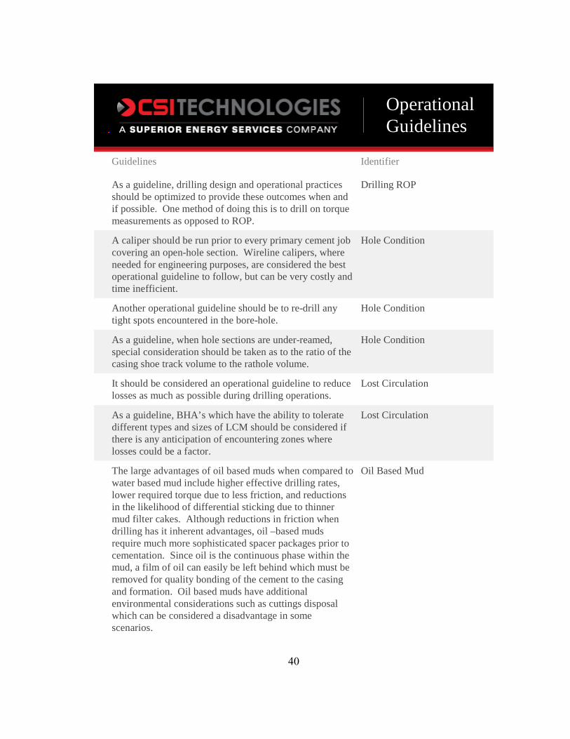
APPENDIX A – OIL BASED MUD DRILLING
OperationalGuidelines
Guidelines Identifier
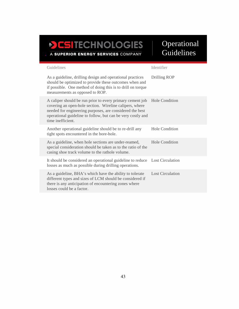
As a guideline, drilling design and operational practices should be optimized to provide these outcomes when and if possible. One method of doing this is to drill on torque measurements as opposed to ROP.
Drilling ROP
A caliper should be run prior to every primary cement job covering an open-hole section. Wireline calipers, where needed for engineering purposes, are considered the best operational guideline to follow, but can be very costly and time inefficient.
Hole Condition
Another operational guideline should be to re-drill any tight spots encountered in the bore-hole.
Hole Condition
As a guideline, when hole sections are under-reamed, special consideration should be taken as to the ratio of the casing shoe track volume to the rathole volume.
Hole Condition
It should be considered an operational guideline to reduce losses as much as possible during drilling operations.
Lost Circulation
As a guideline, BHA’s which have the ability to tolerate different types and sizes of LCM should be considered if there is any anticipation of encountering zones where losses could be a factor.
Lost Circulation
The large advantages of oil based muds when compared to water based mud include higher effective drilling rates, lower required torque due to less friction, and reductions in the likelihood of differential sticking due to thinner mud filter cakes. Although reductions in friction when drilling has it inherent advantages, oil –based muds require much more sophisticated spacer packages prior to cementation. Since oil is the continuous phase within the mud, a film of oil can easily be left behind which must be removed for quality bonding of the cement to the casing and formation. Oil based muds have additional environmental considerations such as cuttings disposal which can be considered a disadvantage in some scenarios.
Oil Based Mud
40

Guidelines Identifier
It should be considered a guideline to pay close attention to the rheological parameters of the mud system during and after conditioning operations. Moderate plastic viscosities and low yield points are considered a guideline to assist the removal of mud during cementation.
Mud Properties
It should be considered a guideline to adhere to spacer volume calculations based on the contact time needed for proper mud removal.
Additional Drilling Considerations
As a guideline, computer simulation programs should be used for anticipation of ECD during hole conditioning operations.
Additional Drilling Considerations
It should be considered a guideline to break circulation very slowly as to not unintentionally fracture the formation.
Additional Drilling Considerations
CSI Technologies makes no representations or warranties, either expressed or implied, and specifically provides the results of this report "as is” based upon the provided information.
41

42
APPENDIX B – WATER BASED MUD DRILLING
OperationalGuidelines
Guidelines Identifier
As a guideline, drilling design and operational practices should be optimized to provide these outcomes when and if possible. One method of doing this is to drill on torque measurements as opposed to ROP.
Drilling ROP
A caliper should be run prior to every primary cement job covering an open-hole section. Wireline calipers, where needed for engineering purposes, are considered the best operational guideline to follow, but can be very costly and time inefficient.
Hole Condition
Another operational guideline should be to re-drill any tight spots encountered in the bore-hole.
Hole Condition
As a guideline, when hole sections are under-reamed, special consideration should be taken as to the ratio of the casing shoe track volume to the rathole volume.
Hole Condition
It should be considered an operational guideline to reduce losses as much as possible during drilling operations.
Lost Circulation
As a guideline, BHA’s which have the ability to tolerate different types and sizes of LCM should be considered if there is any anticipation of encountering zones where losses could be a factor.
Lost Circulation
43
Guidelines Identifier
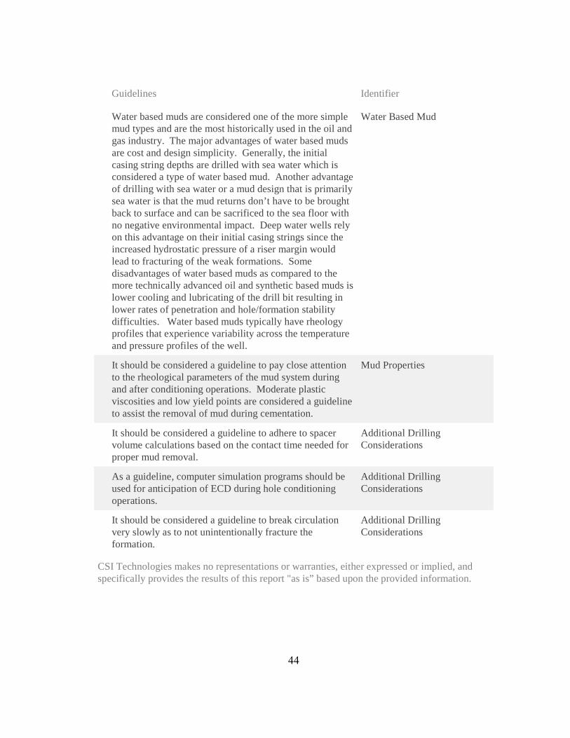
Water based muds are considered one of the more simple mud types and are the most historically used in the oil and gas industry. The major advantages of water based muds are cost and design simplicity. Generally, the initial casing string depths are drilled with sea water which is considered a type of water based mud. Another advantage of drilling with sea water or a mud design that is primarily sea water is that the mud returns don’t have to be brought back to surface and can be sacrificed to the sea floor with no negative environmental impact. Deep water wells rely on this advantage on their initial casing strings since the increased hydrostatic pressure of a riser margin would lead to fracturing of the weak formations. Some disadvantages of water based muds as compared to the more technically advanced oil and synthetic based muds is lower cooling and lubricating of the drill bit resulting in lower rates of penetration and hole/formation stability difficulties. Water based muds typically have rheology profiles that experience variability across the temperature and pressure profiles of the well.
Water Based Mud
It should be considered a guideline to pay close attention to the rheological parameters of the mud system during and after conditioning operations. Moderate plastic viscosities and low yield points are considered a guideline to assist the removal of mud during cementation.
Mud Properties
It should be considered a guideline to adhere to spacer volume calculations based on the contact time needed for proper mud removal.
Additional Drilling Considerations
As a guideline, computer simulation programs should be used for anticipation of ECD during hole conditioning operations.
Additional Drilling Considerations
It should be considered a guideline to break circulation very slowly as to not unintentionally fracture the formation.
Additional Drilling Considerations
CSI Technologies makes no representations or warranties, either expressed or implied, and specifically provides the results of this report "as is” based upon the provided information.
44

45
APPENDIX C – SYNTHETIC BASED MUD DRILLING
OperationalGuidelines
Guidelines Identifier
As a guideline, drilling design and operational practices should be optimized to provide these outcomes when and if possible. One method of doing this is to drill on torque measurements as opposed to ROP.
Drilling ROP
A caliper should be run prior to every primary cement job covering an open-hole section. Wireline calipers, where needed for engineering purposes, are considered the best operational guideline to follow, but can be very costly and time inefficient.
Hole Condition
Another operational guideline should be to re-drill any tight spots encountered in the bore-hole.
Hole Condition
As a guideline, when hole sections are under-reamed, special consideration should be taken as to the ratio of the casing shoe track volume to the rathole volume.
Hole Condition
It should be considered an operational guideline to reduce losses as much as possible during drilling operations.
Lost Circulation
As a guideline, BHA’s which have the ability to tolerate different types and sizes of LCM should be considered if there is any anticipation of encountering zones where losses could be a factor.
Lost Circulation
Synthetic based muds (SBM) should be considered the best option for drilling efficiency while minimizing environmental impact. One inherent disadvantage of SBM is cost. When drilling takes place in zones where total loss is inevitable, a less expensive mud system, rather than SBM may be more advantageous. SBM, like OBM require complex spacer and surfactant packages to reverse the emulsion to water wet casing and formation to allow for good cement bonding characteristics.
Synthetic Based Mud
It should be considered a guideline to pay close attention to the rheological parameters of the mud system during and after conditioning operations. Moderate plastic viscosities and low yield points are considered a guideline to assist the removal of mud during cementation.
Mud Properties
46
Guidelines Identifier
It should be considered a guideline to adhere to spacer volume calculations based on the contact time needed for proper mud removal.
Additional Drilling Considerations
As a guideline, computer simulation programs should be used for anticipation of ECD during hole conditioning operations.
Additional Drilling Considerations
It should be considered a guideline to break circulation very slowly as to not unintentionally fracture the formation.
Additional Drilling Considerations
CSI Technologies makes no representations or warranties, either expressed or implied, and specifically provides the results of this report "as is” based upon the provided information.
47

48
APPENDIX D – SEAFLOOR RETURNS INITIAL CASING PLACEMENT

OperationalGuidelines
Guidelines Identifier
One of the main considerations when discussing the operational guidelines associated with dry cement and additives is documentation and document control.
Dry Cement and Additive Considerations: General Considerations
An operational guideline would be to have a documented chain of custody for all cementing materials arriving on location to be able to easily track lot/batch numbers, chemical manufacture dates, cement QAQC/grind reports, and previous owners/storage locations of the cement and additives.
Dry Cement and Additive Considerations: General Considerations
Record tallies of bulk storage tanks showing a history of cement blends and cleaning operations should also be considered a guideline.
Dry Cement and Additive Considerations: General Considerations
It should be considered a guideline to record the lot numbers of each additive that is dry blended.
Dry Cement and Additive Considerations: Bulk Plant Considerations
All bulk storage tanks should be emptied, cleaned, and inspected regularly. At a minimum, these procedures should be carried out before a new cement blend is placed into the storage tanks. The final quantity and storage tank number should be documented for the blended cement system as well.
Dry Cement and Additive Considerations: Bulk Plant Considerations
Prior to loading or inspecting, the service company should present copies of load tickets to the boat captain and discuss which tanks are to be loaded. Storage tank capacities and hose connections should be verified. After loading, it is recommended to open the tank hatches to verify the amount of cement in each tank.
Dry Cement and Additive Considerations: In Transit Considerations
API RP 65 recommends the use of both top and bottom plugs for all casing cement jobs other than sting-in jobs. The bottom plugs are used as a mechanical separator between fluids while in the casing. Using only two plugs should be considered a minimum guideline. To get the best chances of cementing success, fluid intermixing should be minimized by all means and at all times.
Placement: Cementing Hardware Considerations
49

Guidelines Identifier
It should be considered a guideline to mechanically separate consecutive fluids in the landing string and casing during cementing operations when it will not increase operational complexity.
Placement: Cementing Hardware Considerations
It is also a guideline to reduce the displacement pumping rate prior to the bottom plug reaching any known restrictions within the casing or the float collar. The rate reduction decreases the pressure spike applied to the diaphragm, decreasing the likelihood of premature rupture.
Placement: Cementing Hardware Considerations
While discussing cement heads, it should be considered a guideline to incorporate rotating cement heads when possible such that casing rotation can be achieved during the cement job.
Placement: Cementing Hardware Considerations
Prior to any cement jobs, it should be considered a guideline to calculate the hydraulic horsepower needed to accomplish the operation and compare it to the equipment which will be used on location.
Placement: Cementing Hardware Considerations
. It should also be considered a guideline to install dry product storage bins as close to the mixing equipment, or vice versa, on new rig builds to mitigate the reduction in dry product travel rates.
Placement: Bulk and Liquid Delivery Systems
Adherence to the sample collection procedures within RP 65 should be considered a minimum best practice. For above and beyond cementing guidelines, cement sample collection should be performed during each dry product transfer, whether it is from the bulk plant to the transport vessel or from the rig storage bins to the mixing equipment.
Placement: QC and Sample Collection Considerations
It should be considered a guideline to have manufacture and expiration dates documented for all cementing liquid additives which are on location.
Placement: QC and Sample Collection Considerations
As a guideline, the mix water on location should be tested for chloride content, hardness, and ph.
Placement: QC and Sample Collection Considerations
It should be considered a guideline to keep very close observation of fluid rheology to assist displacement efficiencies. The yield points of sequential fluids should be successively increased such that the viscosity of the displacing fluid tends to overcome the viscosity of the displaced fluid.
Placement: Fluids/Mixing
50
Guidelines Identifier
While discussing the importance of laboratory fluid compatibility testing, it should also be considered a guideline to run contaminated thickening time tests to observe how the contamination will vary the cement system’s set time.
Placement: Fluids/Mixing
When using liquid additives for cementing operations on location, it should be considered a guideline to document the storage tank volumes of the additives prior to the cement job for comparison with post job tank volumes.
Placement: Fluids/Mixing
It should be considered a guideline to record the cementing operations which occur on location. As a minimum, the down hole pumping rate, pump pressure and fluid density should be monitored and recorded for all cementing operations.
Placement: Job Recording and Engineering Simulations
Generally, the mix density will fluctuate more than the down hole density, but it still should be a guideline to minimize the mix density fluctuation as much as possible.
Placement: Job Recording and Engineering Simulations
A guideline is to record the fluid returns through flow-meters during the cement job.
Placement: Job Recording and Engineering Simulations
When discussing cement placement simulation software, it should be considered a guideline to have qualified cementing engineers perform the cementing simulations.
Placement: Job Recording and Engineering Simulations
It should be considered a guideline to perform ECD placement simulations assuming gauge hole and hole with excess, assuming average nitrogen injection rate and varied injection rate, taking into account, changes in slurry rheology, foam quality, temperature and pressure during the foam job.
Placement: Job Recording and Engineering Simulations
Prior to cementing operations it should be considered a guideline to have the pipe capacity from the cementing equipment to the rig floor documented. This is generally a fixed volume, but should be a known and used volume for simulation software and for friction pressure
Placement: Placement Techniques
When using the mud pumps for displacement, it should be a guideline to know ahead of time the pump efficiencies for calculation purposes. As a redundancy, flow meters can be installed on the rig pumps for quality assurance.
Placement: Placement Techniques
51

Guidelines Identifier
During displacement of the cement slurry, it should be considered a guideline to recalculate the displacement volume from anticipated bumps or shears encountered during displacement.
Placement: Placement Techniques
It should also be considered a guideline to slow the displacement rate prior to bumping the plug as to not over pressure any of the equipment.
Placement: Placement Techniques
It should be considered a guideline to compare the pumped volumes and measured pressures from the FIT to the volumes and pressures from the casing test.
Placement: Cement Placement Contingency Planning
If the measured FIT is lower than expected, it should be considered a guideline to modify drilling rates and ECD’s to reduce the likelihood of lost circulation during drilling.
Placement: Cement Placement Contingency Planning
Poor mud displacement and/or hole cleaning can lead to bad FIT results from fluid migration in the cement sheath either through mud channels or micro-annulus paths. In this case, it should be considered a guideline to perform remedial operations on the shoe for better zonal isolation.
Placement: Cement Placement Contingency Planning
When performing shoe squeeze operations, it should be considered a guideline to use the Bradenhead squeeze method, described further within the squeeze cementing subsection.
Placement: Cement Placement Contingency Planning
Prior to performing any primary cementing operations, it should be considered a guideline to have a shoe squeeze contingency plan in place with sufficient materials on location to perform this operation.
Placement: Cement Placement Contingency Planning
It should be considered a guideline to measure or calculate the acoustic impedance of the cement under laboratory conditions prior to the cement job such that wire-line technicians are able to properly calibrate their tools for best results.
Placement: Post Job
. It should also be considered a guideline to not run a bond log until the calculated top of cement (TOC) slurry has reached an acoustic impedance of at least ½ MRayl above the mud’s measured acoustic impedance.
Placement: Post Job
52

Guidelines Identifier
For initial casing strings it should be considered a guideline to perform laboratory testing on the cement slurry at bottom-hole conditions and additional tests should be performed on systems designed for coverage at the mud line.
Initial Casing Strings
The guideline to be followed for these types of slurries is to have a recirculating mixer with automatic density control.
Initial Casing Strings: Fluid Returns to Seafloor
The guideline is to engineer the fluid resident in the well bore to be consistent with the design criteria of the cement job thus avoiding or minimizing undesirable characteristics.
Initial Casing Strings: Fluid Returns to Seafloor
The ability to deal with problem scenarios in a timely manner can mitigate the severity of a given situation, and help to contain the cost of the operation. The guideline is a formal plan that has listings for specialty equipment or material, particularly for exotic or rare items such as unusually large packers, cement retainers, or chemicals.
Initial Casing Strings: Fluid Returns to Seafloor
As a general guideline, the pad mud should have a somewhat low yield point such that the cement slurry does not have to be designed with a higher than normal yield for proper displacement efficiency.
Initial Casing Strings: Fluid Returns to Seafloor
It should be considered a guideline to install a dart catcher sub on the drill pipe to assist with cleaning during the cement job.
Initial Casing Strings: Fluid Returns to Seafloor
CFR 30.250.421 currently requires that conductor casing strings have cemented annuli that reach the mud line. It should be considered a guideline to pump excess cement slurry on initial casing strings to reduce the risk of not having proper cement coverage at the mud line.
Initial Casing Strings: Fluid Returns to Seafloor
It should be considered a guideline to add silica to all cement designs which have the possibility of encountering temperature profiles above 230°F throughout the life of the well.
Production Strings: HP/HT
Special design considerations need to be taken into account when cementing across potential annular flow zones. Currently, operators are required to follow the recommended practices stated within API RP 65-2 as part of the revised Code of Federal Regulations.
Case Specific Formation Considerations: Potential Annular Flow Zone Cementing
53

Guidelines Identifier
Regardless of which approach is taken in the slurry design phase, a full technical analysis of the final slurry and how contact with a salt formation will affect it should be conducted.
Case Specific Formation Considerations: Salt Zone Cementing
It should also be considered a guideline to avoid hanging liners within any salt zones if possible. Liner hangers create annular clearance restrictions which should be avoided due to the salt creep point load considerations.
Case Specific Formation Considerations: Salt Zone Cementing
It should be considered a guideline to use BHA’s that are able to pass LCM through if losses are anticipated.
Case Specific Formation Considerations: Lost Circulation Zone Cementing
It should also be considered a guideline when cementing across known lost circulation zones to have LCM built into the cement design.
Case Specific Formation Considerations: Lost Circulation Zone Cementing
It should be considered a guideline to cure any losses prior to cement placement when possible.
Case Specific Formation Considerations: Lost Circulation Zone Cementing
As a cement placement consideration guideline, pump rates should be increased if losses are encountered during the cement job. Although this statement is counterintuitive, the faster pump rates will ensure better hole cleaning at the shoe.
Case Specific Formation Considerations: Lost Circulation Zone Cementing
There are many recommended guidelines derived from foam cementing case studies which are discussed within the literature review along with documented testing methods discussed within API 10B-4.
Case Specific Formation Considerations: Foam Cementing
There are several additives which as a guideline should be avoided when designing a foam cement system. These additives are: antifoams, dispersants, and potassium chloride.
Case Specific Formation Considerations: Foam Cementing
It should be considered a guideline to have the yield point of the base slurry greater than 10lbf/100ft2.
Case Specific Formation Considerations: Foam Cementing
It should also be considered a best practice to adjust the mixing density of the cement slurry when foaming.
Case Specific Formation Considerations: Foam Cementing
54

Guidelines Identifier
Base slurries with low yield points can also affect the foam quality and foam stability. It should also be considered a guideline to adjust the mixing density of the cement slurry to account for any additives that will be injected downstream of the mixing unit, such as foaming agents and stabilizers.
Case Specific Formation Considerations: Foam Cementing
CSI Technologies makes no representations or warranties, either expressed or implied, and specifically provides the results of this report "as is” based upon the provided information.
55

56
APPENDIX E – SURFACE RETURNS INITIAL CASING PLACEMENT
OperationalGuidelines
Guidelines Identifier
One of the main considerations when discussing the operational guidelines associated with dry cement and additives is documentation and document control.
Dry Cement and Additive Considerations: General Considerations
An operational guideline would be to have a documented chain of custody for all cementing materials arriving on location to be able to easily track lot/batch numbers, chemical manufacture dates, cement QAQC/grind reports, and previous owners/storage locations of the cement and additives.
Dry Cement and Additive Considerations: General Considerations
Record tallies of bulk storage tanks showing a history of cement blends and cleaning operations should also be considered a guideline.
Dry Cement and Additive Considerations: General Considerations
It should be considered a guideline to record the lot numbers of each additive that is dry blended.
Dry Cement and Additive Considerations: Bulk Plant Considerations
All bulk storage tanks should be emptied, cleaned, and inspected regularly. At a minimum, these procedures should be carried out before a new cement blend is placed into the storage tanks. The final quantity and storage tank number should be documented for the blended cement system as well.
Dry Cement and Additive Considerations: Bulk Plant Considerations
Prior to loading or inspecting, the service company should present copies of load tickets to the boat captain and discuss which tanks are to be loaded. Storage tank capacities and hose connections should be verified. After loading, it is recommended to open the tank hatches to verify the amount of cement in each tank.
Dry Cement and Additive Considerations: In Transit Considerations
API RP 65 recommends the use of both top and bottom plugs for all casing cement jobs other than sting-in jobs. The bottom plugs are used as a mechanical separator between fluids while in the casing. Using only two plugs should be considered a minimum guideline. To get the best chances of cementing success, fluid intermixing should be minimized by all means and at all times.
Placement: Cementing Hardware Considerations
57

Guidelines Identifier
It should be considered a guideline to mechanically separate consecutive fluids in the landing string and casing during cementing operations when it will not increase operational complexity.
Placement: Cementing Hardware Considerations
It is also a guideline to reduce the displacement pumping rate prior to the bottom plug reaching any known restrictions within the casing or the float collar. The rate reduction decreases the pressure spike applied to the diaphragm, decreasing the likelihood of premature rupture.
Placement: Cementing Hardware Considerations
While discussing cement heads, it should be considered a guideline to incorporate rotating cement heads when possible such that casing rotation can be achieved during the cement job.
Placement: Cementing Hardware Considerations
Prior to any cement jobs, it should be considered a guideline to calculate the hydraulic horsepower needed to accomplish the operation and compare it to the equipment which will be used on location.
Placement: Cementing Hardware Considerations
. It should also be considered a guideline to install dry product storage bins as close to the mixing equipment, or vice versa, on new rig builds to mitigate the reduction in dry product travel rates.
Placement: Bulk and Liquid Delivery Systems
Adherence to the sample collection procedures within RP 65 should be considered a minimum best practice. For above and beyond cementing guidelines, cement sample collection should be performed during each dry product transfer, whether it is from the bulk plant to the transport vessel or from the rig storage bins to the mixing equipment.
Placement: QC and Sample Collection Considerations
It should be considered a guideline to have manufacture and expiration dates documented for all cementing liquid additives which are on location.
Placement: QC and Sample Collection Considerations
As a guideline, the mix water on location should be tested for chloride content, hardness, and ph.
Placement: QC and Sample Collection Considerations
It should be considered a guideline to keep very close observation of fluid rheology to assist displacement efficiencies. The yield points of sequential fluids should be successively increased such that the viscosity of the displacing fluid tends to overcome the viscosity of the displaced fluid.
Placement: Fluids/Mixing
58

Guidelines Identifier
While discussing the importance of laboratory fluid compatibility testing, it should also be considered a guideline to run contaminated thickening time tests to observe how the contamination will vary the cement system’s set time.
Placement: Fluids/Mixing
When using liquid additives for cementing operations on location, it should be considered a guideline to document the storage tank volumes of the additives prior to the cement job for comparison with post job tank volumes.
Placement: Fluids/Mixing
It should be considered a guideline to record the cementing operations which occur on location. As a minimum, the down hole pumping rate, pump pressure and fluid density should be monitored and recorded for all cementing operations.
Placement: Job Recording and Engineering Simulations
Generally, the mix density will fluctuate more than the down hole density, but it still should be a guideline to minimize the mix density fluctuation as much as possible.
Placement: Job Recording and Engineering Simulations
A guideline is to record the fluid returns through flow-meters during the cement job.
Placement: Job Recording and Engineering Simulations
When discussing cement placement simulation software, it should be considered a guideline to have qualified cementing engineers perform the cementing simulations.
Placement: Job Recording and Engineering Simulations
It should be considered a guideline to perform ECD placement simulations assuming gauge hole and hole with excess, assuming average nitrogen injection rate and varied injection rate, taking into account, changes in slurry rheology, foam quality, temperature and pressure during the foam job.
Placement: Job Recording and Engineering Simulations
Prior to cementing operations it should be considered a guideline to have the pipe capacity from the cementing equipment to the rig floor documented. This is generally a fixed volume, but should be a known and used volume for simulation software and for friction pressure
Placement: Placement Techniques
When using the mud pumps for displacement, it should be a guideline to know ahead of time the pump efficiencies for calculation purposes. As a redundancy, flow meters can be installed on the rig pumps for quality assurance.
Placement: Placement Techniques
59

Guidelines Identifier
During displacement of the cement slurry, it should be considered a guideline to recalculate the displacement volume from anticipated bumps or shears encountered during displacement.
Placement: Placement Techniques
It should also be considered a guideline to slow the displacement rate prior to bumping the plug as to not over pressure any of the equipment.
Placement: Placement Techniques
It should be considered a guideline to compare the pumped volumes and measured pressures from the FIT to the volumes and pressures from the casing test.
Placement: Cement Placement Contingency Planning
If the measured FIT is lower than expected, it should be considered a guideline to modify drilling rates and ECD’s to reduce the likelihood of lost circulation during drilling.
Placement: Cement Placement Contingency Planning
Poor mud displacement and/or hole cleaning can lead to bad FIT results from fluid migration in the cement sheath either through mud channels or micro-annulus paths. In this case, it should be considered a guideline to perform remedial operations on the shoe for better zonal isolation.
Placement: Cement Placement Contingency Planning
When performing shoe squeeze operations, it should be considered a guideline to use the Bradenhead squeeze method, described further within the squeeze cementing subsection.
Placement: Cement Placement Contingency Planning
Prior to performing any primary cementing operations, it should be considered a guideline to have a shoe squeeze contingency plan in place with sufficient materials on location to perform this operation.
Placement: Cement Placement Contingency Planning
It should be considered a guideline to measure or calculate the acoustic impedance of the cement under laboratory conditions prior to the cement job such that wire-line technicians are able to properly calibrate their tools for best results.
Placement: Post Job
. It should also be considered a guideline to not run a bond log until the calculated top of cement (TOC) slurry has reached an acoustic impedance of at least ½ MRayl above the mud’s measured acoustic impedance.
Placement: Post Job
60

Guidelines Identifier
For initial casing strings it should be considered a guideline to perform laboratory testing on the cement slurry at bottom-hole conditions and additional tests should be performed on systems designed for coverage at the mud line.
Initial Casing Strings
The annular clearance of the drive pipe section is much larger than the annular clearance from the open hole section. It should be considered a guideline to incorporate these geometries into placement simulations to anticipate their displacement efficiencies.
Initial Casing Strings: Fluid Returns to Surface
It should be considered a guideline to add silica to all cement designs which have the possibility of encountering temperature profiles above 230°F throughout the life of the well.
Production Strings: HP/HT
Special design considerations need to be taken into account when cementing across potential annular flow zones. Currently, operators are required to follow the recommended practices stated within API RP 65-2 as part of the revised Code of Federal Regulations.
Case Specific Formation Considerations: Potential Annular Flow Zone Cementing
Regardless of which approach is taken in the slurry design phase, a full technical analysis of the final slurry and how contact with a salt formation will affect it should be conducted.
Case Specific Formation Considerations: Salt Zone Cementing
It should also be considered a guideline to avoid hanging liners within any salt zones if possible. Liner hangers create annular clearance restrictions which should be avoided due to the salt creep point load considerations.
Case Specific Formation Considerations: Salt Zone Cementing
It should be considered a guideline to use BHA’s that are able to pass LCM through if losses are anticipated.
Case Specific Formation Considerations: Lost Circulation Zone Cementing
It should also be considered a guideline when cementing across known lost circulation zones to have LCM built into the cement design.
Case Specific Formation Considerations: Lost Circulation Zone Cementing
It should be considered a guideline to cure any losses prior to cement placement when possible.
Case Specific Formation Considerations: Lost Circulation Zone Cementing
61
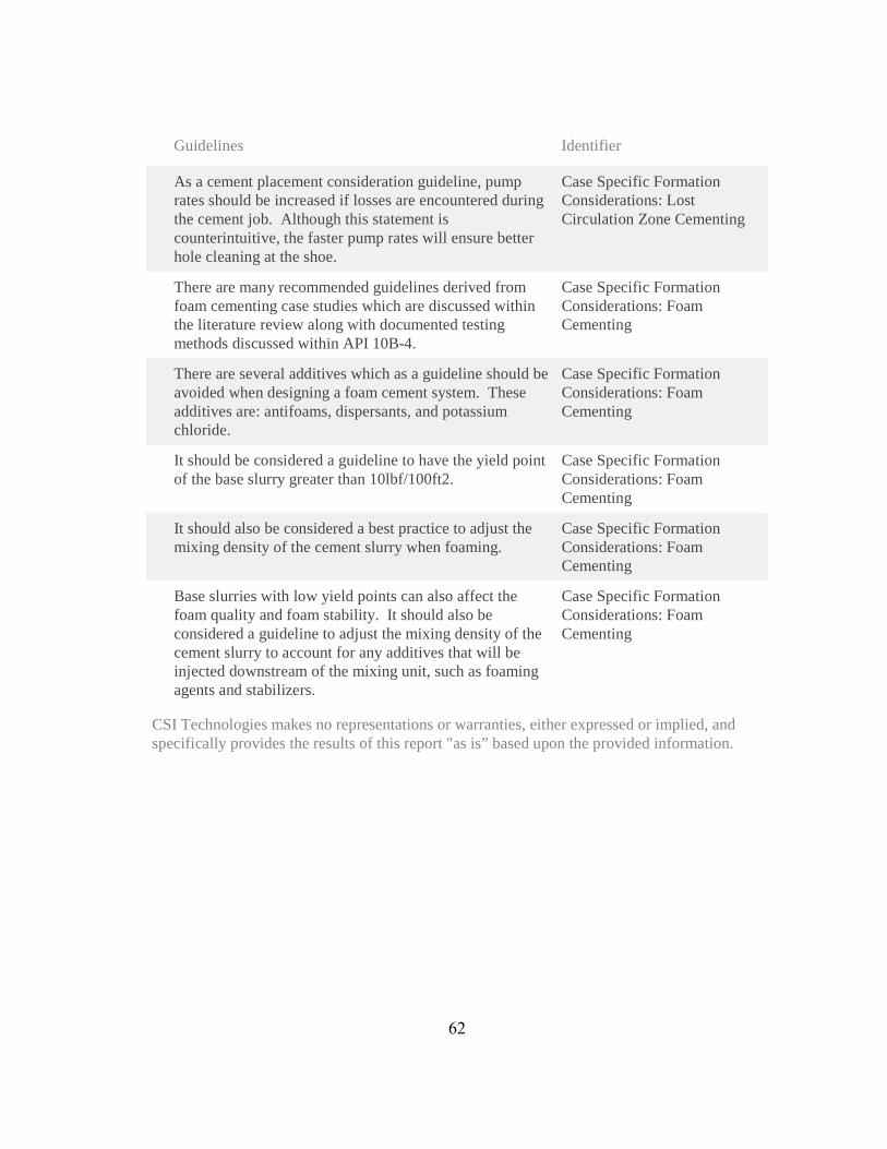
Guidelines Identifier
As a cement placement consideration guideline, pump rates should be increased if losses are encountered during the cement job. Although this statement is counterintuitive, the faster pump rates will ensure better hole cleaning at the shoe.
Case Specific Formation Considerations: Lost Circulation Zone Cementing
There are many recommended guidelines derived from foam cementing case studies which are discussed within the literature review along with documented testing methods discussed within API 10B-4.
Case Specific Formation Considerations: Foam Cementing
There are several additives which as a guideline should be avoided when designing a foam cement system. These additives are: antifoams, dispersants, and potassium chloride.
Case Specific Formation Considerations: Foam Cementing
It should be considered a guideline to have the yield point of the base slurry greater than 10lbf/100ft2.
Case Specific Formation Considerations: Foam Cementing
It should also be considered a best practice to adjust the mixing density of the cement slurry when foaming.
Case Specific Formation Considerations: Foam Cementing
Base slurries with low yield points can also affect the foam quality and foam stability. It should also be considered a guideline to adjust the mixing density of the cement slurry to account for any additives that will be injected downstream of the mixing unit, such as foaming agents and stabilizers.
Case Specific Formation Considerations: Foam Cementing
CSI Technologies makes no representations or warranties, either expressed or implied, and specifically provides the results of this report "as is” based upon the provided information.
62

63
APPENDIX F – INTERMEDIATE CASING PLACEMENT

OperationalGuidelines
Guidelines Identifier
One of the main considerations when discussing the operational guidelines associated with dry cement and additives is documentation and document control.
Dry Cement and Additive Considerations: General Considerations
An operational guideline would be to have a documented chain of custody for all cementing materials arriving on location to be able to easily track lot/batch numbers, chemical manufacture dates, cement QAQC/grind reports, and previous owners/storage locations of the cement and additives.
Dry Cement and Additive Considerations: General Considerations
Record tallies of bulk storage tanks showing a history of cement blends and cleaning operations should also be considered a guideline.
Dry Cement and Additive Considerations: General Considerations
It should be considered a guideline to record the lot numbers of each additive that is dry blended.
Dry Cement and Additive Considerations: Bulk Plant Considerations
All bulk storage tanks should be emptied, cleaned, and inspected regularly. At a minimum, these procedures should be carried out before a new cement blend is placed into the storage tanks. The final quantity and storage tank number should be documented for the blended cement system as well.
Dry Cement and Additive Considerations: Bulk Plant Considerations
Prior to loading or inspecting, the service company should present copies of load tickets to the boat captain and discuss which tanks are to be loaded. Storage tank capacities and hose connections should be verified. After loading, it is recommended to open the tank hatches to verify the amount of cement in each tank.
Dry Cement and Additive Considerations: In Transit Considerations
API RP 65 recommends the use of both top and bottom plugs for all casing cement jobs other than sting-in jobs. The bottom plugs are used as a mechanical separator between fluids while in the casing. Using only two plugs should be considered a minimum guideline. To get the best chances of cementing success, fluid intermixing should be minimized by all means and at all times.
Placement: Cementing Hardware Considerations
64

Guidelines Identifier
It should be considered a guideline to mechanically separate consecutive fluids in the landing string and casing during cementing operations when it will not increase operational complexity.
Placement: Cementing Hardware Considerations
It is also a guideline to reduce the displacement pumping rate prior to the bottom plug reaching any known restrictions within the casing or the float collar. The rate reduction decreases the pressure spike applied to the diaphragm, decreasing the likelihood of premature rupture.
Placement: Cementing Hardware Considerations
While discussing cement heads, it should be considered a guideline to incorporate rotating cement heads when possible such that casing rotation can be achieved during the cement job.
Placement: Cementing Hardware Considerations
Prior to any cement jobs, it should be considered a guideline to calculate the hydraulic horsepower needed to accomplish the operation and compare it to the equipment which will be used on location.
Placement: Cementing Hardware Considerations
. It should also be considered a guideline to install dry product storage bins as close to the mixing equipment, or vice versa, on new rig builds to mitigate the reduction in dry product travel rates.
Placement: Bulk and Liquid Delivery Systems
Adherence to the sample collection procedures within RP 65 should be considered a minimum best practice. For above and beyond cementing guidelines, cement sample collection should be performed during each dry product transfer, whether it is from the bulk plant to the transport vessel or from the rig storage bins to the mixing equipment.
Placement: QC and Sample Collection Considerations
It should be considered a guideline to have manufacture and expiration dates documented for all cementing liquid additives which are on location.
Placement: QC and Sample Collection Considerations
As a guideline, the mix water on location should be tested for chloride content, hardness, and ph.
Placement: QC and Sample Collection Considerations
It should be considered a guideline to keep very close observation of fluid rheology to assist displacement efficiencies. The yield points of sequential fluids should be successively increased such that the viscosity of the displacing fluid tends to overcome the viscosity of the displaced fluid.
Placement: Fluids/Mixing
65

Guidelines Identifier
While discussing the importance of laboratory fluid compatibility testing, it should also be considered a guideline to run contaminated thickening time tests to observe how the contamination will vary the cement system’s set time.
Placement: Fluids/Mixing
When using liquid additives for cementing operations on location, it should be considered a guideline to document the storage tank volumes of the additives prior to the cement job for comparison with post job tank volumes.
Placement: Fluids/Mixing
It should be considered a guideline to record the cementing operations which occur on location. As a minimum, the down hole pumping rate, pump pressure and fluid density should be monitored and recorded for all cementing operations.
Placement: Job Recording and Engineering Simulations
Generally, the mix density will fluctuate more than the down hole density, but it still should be a guideline to minimize the mix density fluctuation as much as possible.
Placement: Job Recording and Engineering Simulations
A guideline is to record the fluid returns through flow-meters during the cement job.
Placement: Job Recording and Engineering Simulations
When discussing cement placement simulation software, it should be considered a guideline to have qualified cementing engineers perform the cementing simulations.
Placement: Job Recording and Engineering Simulations
It should be considered a guideline to perform ECD placement simulations assuming gauge hole and hole with excess, assuming average nitrogen injection rate and varied injection rate, taking into account, changes in slurry rheology, foam quality, temperature and pressure during the foam job.
Placement: Job Recording and Engineering Simulations
Prior to cementing operations it should be considered a guideline to have the pipe capacity from the cementing equipment to the rig floor documented. This is generally a fixed volume, but should be a known and used volume for simulation software and for friction pressure
Placement: Placement Techniques
When using the mud pumps for displacement, it should be a guideline to know ahead of time the pump efficiencies for calculation purposes. As a redundancy, flow meters can be installed on the rig pumps for quality assurance.
Placement: Placement Techniques
66
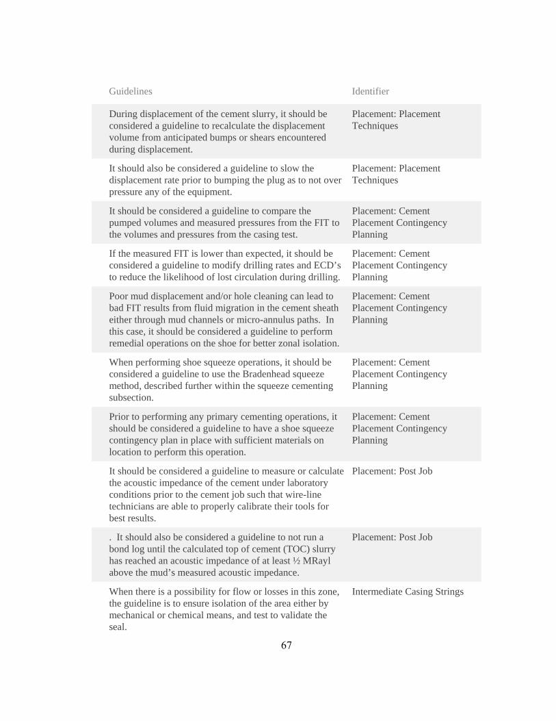
Guidelines Identifier
During displacement of the cement slurry, it should be considered a guideline to recalculate the displacement volume from anticipated bumps or shears encountered during displacement.
Placement: Placement Techniques
It should also be considered a guideline to slow the displacement rate prior to bumping the plug as to not over pressure any of the equipment.
Placement: Placement Techniques
It should be considered a guideline to compare the pumped volumes and measured pressures from the FIT to the volumes and pressures from the casing test.
Placement: Cement Placement Contingency Planning
If the measured FIT is lower than expected, it should be considered a guideline to modify drilling rates and ECD’s to reduce the likelihood of lost circulation during drilling.
Placement: Cement Placement Contingency Planning
Poor mud displacement and/or hole cleaning can lead to bad FIT results from fluid migration in the cement sheath either through mud channels or micro-annulus paths. In this case, it should be considered a guideline to perform remedial operations on the shoe for better zonal isolation.
Placement: Cement Placement Contingency Planning
When performing shoe squeeze operations, it should be considered a guideline to use the Bradenhead squeeze method, described further within the squeeze cementing subsection.
Placement: Cement Placement Contingency Planning
Prior to performing any primary cementing operations, it should be considered a guideline to have a shoe squeeze contingency plan in place with sufficient materials on location to perform this operation.
Placement: Cement Placement Contingency Planning
It should be considered a guideline to measure or calculate the acoustic impedance of the cement under laboratory conditions prior to the cement job such that wire-line technicians are able to properly calibrate their tools for best results.
Placement: Post Job
. It should also be considered a guideline to not run a bond log until the calculated top of cement (TOC) slurry has reached an acoustic impedance of at least ½ MRayl above the mud’s measured acoustic impedance.
Placement: Post Job
When there is a possibility for flow or losses in this zone, the guideline is to ensure isolation of the area either by mechanical or chemical means, and test to validate the seal.
Intermediate Casing Strings
67
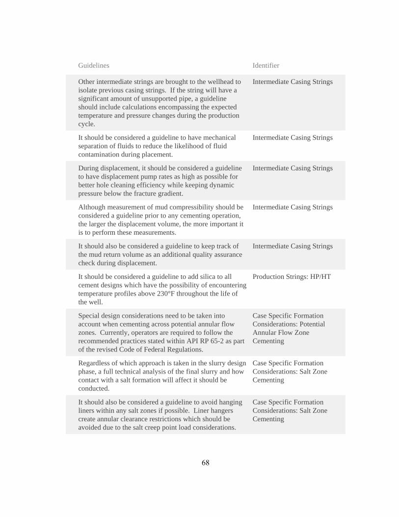
Guidelines Identifier
Other intermediate strings are brought to the wellhead to isolate previous casing strings. If the string will have a significant amount of unsupported pipe, a guideline should include calculations encompassing the expected temperature and pressure changes during the production cycle.
Intermediate Casing Strings
It should be considered a guideline to have mechanical separation of fluids to reduce the likelihood of fluid contamination during placement.
Intermediate Casing Strings
During displacement, it should be considered a guideline to have displacement pump rates as high as possible for better hole cleaning efficiency while keeping dynamic pressure below the fracture gradient.
Intermediate Casing Strings
Although measurement of mud compressibility should be considered a guideline prior to any cementing operation, the larger the displacement volume, the more important it is to perform these measurements.
Intermediate Casing Strings
It should also be considered a guideline to keep track of the mud return volume as an additional quality assurance check during displacement.
Intermediate Casing Strings
It should be considered a guideline to add silica to all cement designs which have the possibility of encountering temperature profiles above 230°F throughout the life of the well.
Production Strings: HP/HT
Special design considerations need to be taken into account when cementing across potential annular flow zones. Currently, operators are required to follow the recommended practices stated within API RP 65-2 as part of the revised Code of Federal Regulations.
Case Specific Formation Considerations: Potential Annular Flow Zone Cementing
Regardless of which approach is taken in the slurry design phase, a full technical analysis of the final slurry and how contact with a salt formation will affect it should be conducted.
Case Specific Formation Considerations: Salt Zone Cementing
It should also be considered a guideline to avoid hanging liners within any salt zones if possible. Liner hangers create annular clearance restrictions which should be avoided due to the salt creep point load considerations.
Case Specific Formation Considerations: Salt Zone Cementing
68
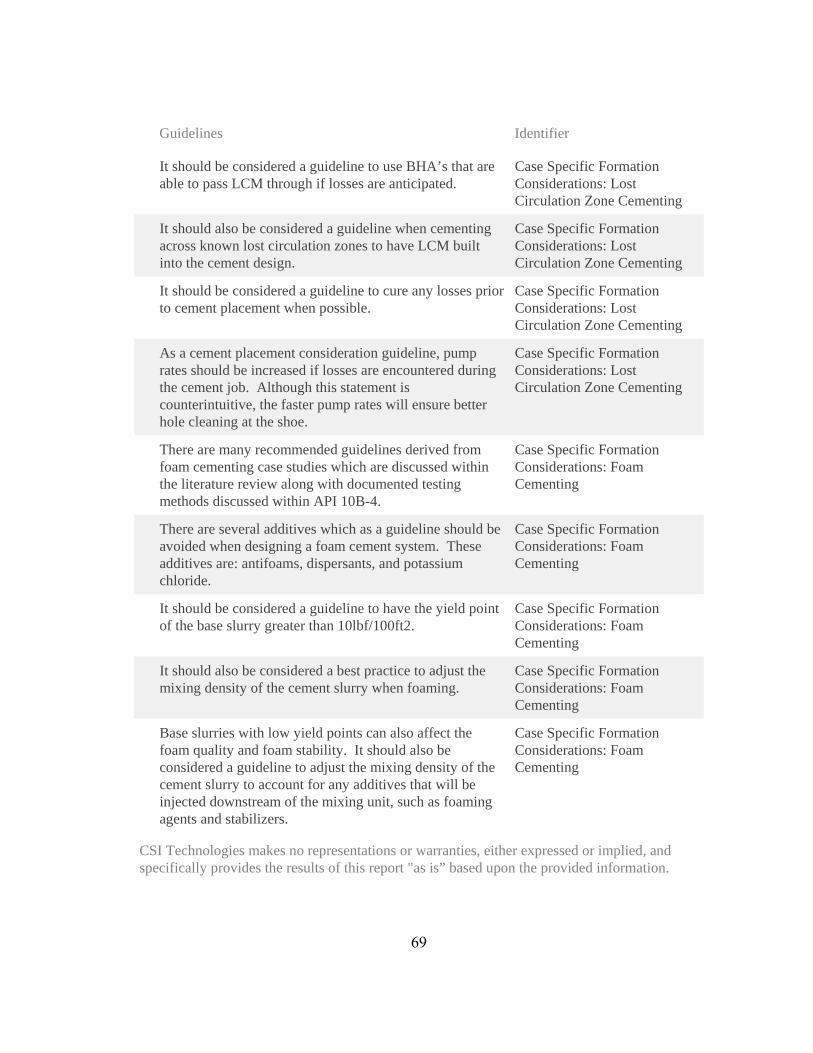
Guidelines Identifier
It should be considered a guideline to use BHA’s that are able to pass LCM through if losses are anticipated.
Case Specific Formation Considerations: Lost Circulation Zone Cementing
It should also be considered a guideline when cementing across known lost circulation zones to have LCM built into the cement design.
Case Specific Formation Considerations: Lost Circulation Zone Cementing
It should be considered a guideline to cure any losses prior to cement placement when possible.
Case Specific Formation Considerations: Lost Circulation Zone Cementing
As a cement placement consideration guideline, pump rates should be increased if losses are encountered during the cement job. Although this statement is counterintuitive, the faster pump rates will ensure better hole cleaning at the shoe.
Case Specific Formation Considerations: Lost Circulation Zone Cementing
There are many recommended guidelines derived from foam cementing case studies which are discussed within the literature review along with documented testing methods discussed within API 10B-4.
Case Specific Formation Considerations: Foam Cementing
There are several additives which as a guideline should be avoided when designing a foam cement system. These additives are: antifoams, dispersants, and potassium chloride.
Case Specific Formation Considerations: Foam Cementing
It should be considered a guideline to have the yield point of the base slurry greater than 10lbf/100ft2.
Case Specific Formation Considerations: Foam Cementing
It should also be considered a best practice to adjust the mixing density of the cement slurry when foaming.
Case Specific Formation Considerations: Foam Cementing
Base slurries with low yield points can also affect the foam quality and foam stability. It should also be considered a guideline to adjust the mixing density of the cement slurry to account for any additives that will be injected downstream of the mixing unit, such as foaming agents and stabilizers.
Case Specific Formation Considerations: Foam Cementing
CSI Technologies makes no representations or warranties, either expressed or implied, and specifically provides the results of this report "as is” based upon the provided information.
69

70
APPENDIX G – VERTICAL PRODUCTION CASING PLACEMENT

OperationalGuidelines
Guidelines Identifier
One of the main considerations when discussing the operational guidelines associated with dry cement and additives is documentation and document control.
Dry Cement and Additive Considerations: General Considerations
An operational guideline would be to have a documented chain of custody for all cementing materials arriving on location to be able to easily track lot/batch numbers, chemical manufacture dates, cement QAQC/grind reports, and previous owners/storage locations of the cement and additives.
Dry Cement and Additive Considerations: General Considerations
Record tallies of bulk storage tanks showing a history of cement blends and cleaning operations should also be considered a guideline.
Dry Cement and Additive Considerations: General Considerations
It should be considered a guideline to record the lot numbers of each additive that is dry blended.
Dry Cement and Additive Considerations: Bulk Plant Considerations
All bulk storage tanks should be emptied, cleaned, and inspected regularly. At a minimum, these procedures should be carried out before a new cement blend is placed into the storage tanks. The final quantity and storage tank number should be documented for the blended cement system as well.
Dry Cement and Additive Considerations: Bulk Plant Considerations
Prior to loading or inspecting, the service company should present copies of load tickets to the boat captain and discuss which tanks are to be loaded. Storage tank capacities and hose connections should be verified. After loading, it is recommended to open the tank hatches to verify the amount of cement in each tank.
Dry Cement and Additive Considerations: In Transit Considerations
API RP 65 recommends the use of both top and bottom plugs for all casing cement jobs other than sting-in jobs. The bottom plugs are used as a mechanical separator between fluids while in the casing. Using only two plugs should be considered a minimum guideline. To get the best chances of cementing success, fluid intermixing should be minimized by all means and at all times.
Placement: Cementing Hardware Considerations
71
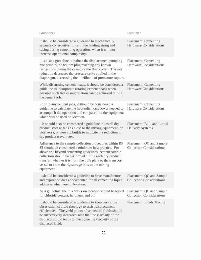
Guidelines Identifier
It should be considered a guideline to mechanically separate consecutive fluids in the landing string and casing during cementing operations when it will not increase operational complexity.
Placement: Cementing Hardware Considerations
It is also a guideline to reduce the displacement pumping rate prior to the bottom plug reaching any known restrictions within the casing or the float collar. The rate reduction decreases the pressure spike applied to the diaphragm, decreasing the likelihood of premature rupture.
Placement: Cementing Hardware Considerations
While discussing cement heads, it should be considered a guideline to incorporate rotating cement heads when possible such that casing rotation can be achieved during the cement job.
Placement: Cementing Hardware Considerations
Prior to any cement jobs, it should be considered a guideline to calculate the hydraulic horsepower needed to accomplish the operation and compare it to the equipment which will be used on location.
Placement: Cementing Hardware Considerations
. It should also be considered a guideline to install dry product storage bins as close to the mixing equipment, or vice versa, on new rig builds to mitigate the reduction in dry product travel rates.
Placement: Bulk and Liquid Delivery Systems
Adherence to the sample collection procedures within RP 65 should be considered a minimum best practice. For above and beyond cementing guidelines, cement sample collection should be performed during each dry product transfer, whether it is from the bulk plant to the transport vessel or from the rig storage bins to the mixing equipment.
Placement: QC and Sample Collection Considerations
It should be considered a guideline to have manufacture and expiration dates documented for all cementing liquid additives which are on location.
Placement: QC and Sample Collection Considerations
As a guideline, the mix water on location should be tested for chloride content, hardness, and ph.
Placement: QC and Sample Collection Considerations
It should be considered a guideline to keep very close observation of fluid rheology to assist displacement efficiencies. The yield points of sequential fluids should be successively increased such that the viscosity of the displacing fluid tends to overcome the viscosity of the displaced fluid.
Placement: Fluids/Mixing
72

Guidelines Identifier
While discussing the importance of laboratory fluid compatibility testing, it should also be considered a guideline to run contaminated thickening time tests to observe how the contamination will vary the cement system’s set time.
Placement: Fluids/Mixing
When using liquid additives for cementing operations on location, it should be considered a guideline to document the storage tank volumes of the additives prior to the cement job for comparison with post job tank volumes.
Placement: Fluids/Mixing
It should be considered a guideline to record the cementing operations which occur on location. As a minimum, the down hole pumping rate, pump pressure and fluid density should be monitored and recorded for all cementing operations.
Placement: Job Recording and Engineering Simulations
Generally, the mix density will fluctuate more than the down hole density, but it still should be a guideline to minimize the mix density fluctuation as much as possible.
Placement: Job Recording and Engineering Simulations
A guideline is to record the fluid returns through flow-meters during the cement job.
Placement: Job Recording and Engineering Simulations
When discussing cement placement simulation software, it should be considered a guideline to have qualified cementing engineers perform the cementing simulations.
Placement: Job Recording and Engineering Simulations
It should be considered a guideline to perform ECD placement simulations assuming gauge hole and hole with excess, assuming average nitrogen injection rate and varied injection rate, taking into account, changes in slurry rheology, foam quality, temperature and pressure during the foam job.
Placement: Job Recording and Engineering Simulations
Prior to cementing operations it should be considered a guideline to have the pipe capacity from the cementing equipment to the rig floor documented. This is generally a fixed volume, but should be a known and used volume for simulation software and for friction pressure
Placement: Placement Techniques
When using the mud pumps for displacement, it should be a guideline to know ahead of time the pump efficiencies for calculation purposes. As a redundancy, flow meters can be installed on the rig pumps for quality assurance.
Placement: Placement Techniques
73

Guidelines Identifier
During displacement of the cement slurry, it should be considered a guideline to recalculate the displacement volume from anticipated bumps or shears encountered during displacement.
Placement: Placement Techniques
It should also be considered a guideline to slow the displacement rate prior to bumping the plug as to not over pressure any of the equipment.
Placement: Placement Techniques
It should be considered a guideline to compare the pumped volumes and measured pressures from the FIT to the volumes and pressures from the casing test.
Placement: Cement Placement Contingency Planning
If the measured FIT is lower than expected, it should be considered a guideline to modify drilling rates and ECD’s to reduce the likelihood of lost circulation during drilling.
Placement: Cement Placement Contingency Planning
Poor mud displacement and/or hole cleaning can lead to bad FIT results from fluid migration in the cement sheath either through mud channels or micro-annulus paths. In this case, it should be considered a guideline to perform remedial operations on the shoe for better zonal isolation.
Placement: Cement Placement Contingency Planning
When performing shoe squeeze operations, it should be considered a guideline to use the Bradenhead squeeze method, described further within the squeeze cementing subsection.
Placement: Cement Placement Contingency Planning
Prior to performing any primary cementing operations, it should be considered a guideline to have a shoe squeeze contingency plan in place with sufficient materials on location to perform this operation.
Placement: Cement Placement Contingency Planning
It should be considered a guideline to measure or calculate the acoustic impedance of the cement under laboratory conditions prior to the cement job such that wire-line technicians are able to properly calibrate their tools for best results.
Placement: Post Job
. It should also be considered a guideline to not run a bond log until the calculated top of cement (TOC) slurry has reached an acoustic impedance of at least ½ MRayl above the mud’s measured acoustic impedance.
Placement: Post Job
74
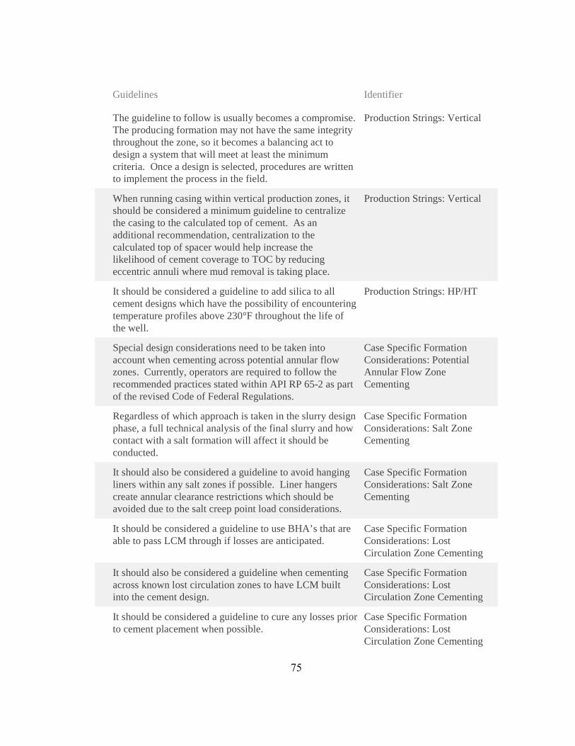
Guidelines Identifier
The guideline to follow is usually becomes a compromise. The producing formation may not have the same integrity throughout the zone, so it becomes a balancing act to design a system that will meet at least the minimum criteria. Once a design is selected, procedures are written to implement the process in the field.
Production Strings: Vertical
When running casing within vertical production zones, it should be considered a minimum guideline to centralize the casing to the calculated top of cement. As an additional recommendation, centralization to the calculated top of spacer would help increase the likelihood of cement coverage to TOC by reducing eccentric annuli where mud removal is taking place.
Production Strings: Vertical
It should be considered a guideline to add silica to all cement designs which have the possibility of encountering temperature profiles above 230°F throughout the life of the well.
Production Strings: HP/HT
Special design considerations need to be taken into account when cementing across potential annular flow zones. Currently, operators are required to follow the recommended practices stated within API RP 65-2 as part of the revised Code of Federal Regulations.
Case Specific Formation Considerations: Potential Annular Flow Zone Cementing
Regardless of which approach is taken in the slurry design phase, a full technical analysis of the final slurry and how contact with a salt formation will affect it should be conducted.
Case Specific Formation Considerations: Salt Zone Cementing
It should also be considered a guideline to avoid hanging liners within any salt zones if possible. Liner hangers create annular clearance restrictions which should be avoided due to the salt creep point load considerations.
Case Specific Formation Considerations: Salt Zone Cementing
It should be considered a guideline to use BHA’s that are able to pass LCM through if losses are anticipated.
Case Specific Formation Considerations: Lost Circulation Zone Cementing
It should also be considered a guideline when cementing across known lost circulation zones to have LCM built into the cement design.
Case Specific Formation Considerations: Lost Circulation Zone Cementing
It should be considered a guideline to cure any losses prior to cement placement when possible.
Case Specific Formation Considerations: Lost Circulation Zone Cementing
75

Guidelines Identifier
As a cement placement consideration guideline, pump rates should be increased if losses are encountered during the cement job. Although this statement is counterintuitive, the faster pump rates will ensure better hole cleaning at the shoe.
Case Specific Formation Considerations: Lost Circulation Zone Cementing
There are many recommended guidelines derived from foam cementing case studies which are discussed within the literature review along with documented testing methods discussed within API 10B-4.
Case Specific Formation Considerations: Foam Cementing
There are several additives which as a guideline should be avoided when designing a foam cement system. These additives are: antifoams, dispersants, and potassium chloride.
Case Specific Formation Considerations: Foam Cementing
It should be considered a guideline to have the yield point of the base slurry greater than 10lbf/100ft2.
Case Specific Formation Considerations: Foam Cementing
It should also be considered a best practice to adjust the mixing density of the cement slurry when foaming.
Case Specific Formation Considerations: Foam Cementing
Base slurries with low yield points can also affect the foam quality and foam stability. It should also be considered a guideline to adjust the mixing density of the cement slurry to account for any additives that will be injected downstream of the mixing unit, such as foaming agents and stabilizers.
Case Specific Formation Considerations: Foam Cementing
CSI Technologies makes no representations or warranties, either expressed or implied, and specifically provides the results of this report "as is” based upon the provided information.
76

77
APPENDIX H – HORIZONTAL PRODUCTION CASING PLACEMENT

OperationalGuidelines
Guidelines Identifier
One of the main considerations when discussing the operational guidelines associated with dry cement and additives is documentation and document control.
Dry Cement and Additive Considerations: General Considerations
An operational guideline would be to have a documented chain of custody for all cementing materials arriving on location to be able to easily track lot/batch numbers, chemical manufacture dates, cement QAQC/grind reports, and previous owners/storage locations of the cement and additives.
Dry Cement and Additive Considerations: General Considerations
Record tallies of bulk storage tanks showing a history of cement blends and cleaning operations should also be considered a guideline.
Dry Cement and Additive Considerations: General Considerations
It should be considered a guideline to record the lot numbers of each additive that is dry blended.
Dry Cement and Additive Considerations: Bulk Plant Considerations
All bulk storage tanks should be emptied, cleaned, and inspected regularly. At a minimum, these procedures should be carried out before a new cement blend is placed into the storage tanks. The final quantity and storage tank number should be documented for the blended cement system as well.
Dry Cement and Additive Considerations: Bulk Plant Considerations
Prior to loading or inspecting, the service company should present copies of load tickets to the boat captain and discuss which tanks are to be loaded. Storage tank capacities and hose connections should be verified. After loading, it is recommended to open the tank hatches to verify the amount of cement in each tank.
Dry Cement and Additive Considerations: In Transit Considerations
API RP 65 recommends the use of both top and bottom plugs for all casing cement jobs other than sting-in jobs. The bottom plugs are used as a mechanical separator between fluids while in the casing. Using only two plugs should be considered a minimum guideline. To get the best chances of cementing success, fluid intermixing should be minimized by all means and at all times.
Placement: Cementing Hardware Considerations
78

Guidelines Identifier
It should be considered a guideline to mechanically separate consecutive fluids in the landing string and casing during cementing operations when it will not increase operational complexity.
Placement: Cementing Hardware Considerations
It is also a guideline to reduce the displacement pumping rate prior to the bottom plug reaching any known restrictions within the casing or the float collar. The rate reduction decreases the pressure spike applied to the diaphragm, decreasing the likelihood of premature rupture.
Placement: Cementing Hardware Considerations
While discussing cement heads, it should be considered a guideline to incorporate rotating cement heads when possible such that casing rotation can be achieved during the cement job.
Placement: Cementing Hardware Considerations
Prior to any cement jobs, it should be considered a guideline to calculate the hydraulic horsepower needed to accomplish the operation and compare it to the equipment which will be used on location.
Placement: Cementing Hardware Considerations
. It should also be considered a guideline to install dry product storage bins as close to the mixing equipment, or vice versa, on new rig builds to mitigate the reduction in dry product travel rates.
Placement: Bulk and Liquid Delivery Systems
Adherence to the sample collection procedures within RP 65 should be considered a minimum best practice. For above and beyond cementing guidelines, cement sample collection should be performed during each dry product transfer, whether it is from the bulk plant to the transport vessel or from the rig storage bins to the mixing equipment.
Placement: QC and Sample Collection Considerations
It should be considered a guideline to have manufacture and expiration dates documented for all cementing liquid additives which are on location.
Placement: QC and Sample Collection Considerations
As a guideline, the mix water on location should be tested for chloride content, hardness, and ph.
Placement: QC and Sample Collection Considerations
It should be considered a guideline to keep very close observation of fluid rheology to assist displacement efficiencies. The yield points of sequential fluids should be successively increased such that the viscosity of the displacing fluid tends to overcome the viscosity of the displaced fluid.
Placement: Fluids/Mixing
79

Guidelines Identifier
While discussing the importance of laboratory fluid compatibility testing, it should also be considered a guideline to run contaminated thickening time tests to observe how the contamination will vary the cement system’s set time.
Placement: Fluids/Mixing
When using liquid additives for cementing operations on location, it should be considered a guideline to document the storage tank volumes of the additives prior to the cement job for comparison with post job tank volumes.
Placement: Fluids/Mixing
It should be considered a guideline to record the cementing operations which occur on location. As a minimum, the down hole pumping rate, pump pressure and fluid density should be monitored and recorded for all cementing operations.
Placement: Job Recording and Engineering Simulations
Generally, the mix density will fluctuate more than the down hole density, but it still should be a guideline to minimize the mix density fluctuation as much as possible.
Placement: Job Recording and Engineering Simulations
A guideline is to record the fluid returns through flow-meters during the cement job.
Placement: Job Recording and Engineering Simulations
When discussing cement placement simulation software, it should be considered a guideline to have qualified cementing engineers perform the cementing simulations.
Placement: Job Recording and Engineering Simulations
It should be considered a guideline to perform ECD placement simulations assuming gauge hole and hole with excess, assuming average nitrogen injection rate and varied injection rate, taking into account, changes in slurry rheology, foam quality, temperature and pressure during the foam job.
Placement: Job Recording and Engineering Simulations
Prior to cementing operations it should be considered a guideline to have the pipe capacity from the cementing equipment to the rig floor documented. This is generally a fixed volume, but should be a known and used volume for simulation software and for friction pressure
Placement: Placement Techniques
When using the mud pumps for displacement, it should be a guideline to know ahead of time the pump efficiencies for calculation purposes. As a redundancy, flow meters can be installed on the rig pumps for quality assurance.
Placement: Placement Techniques
80
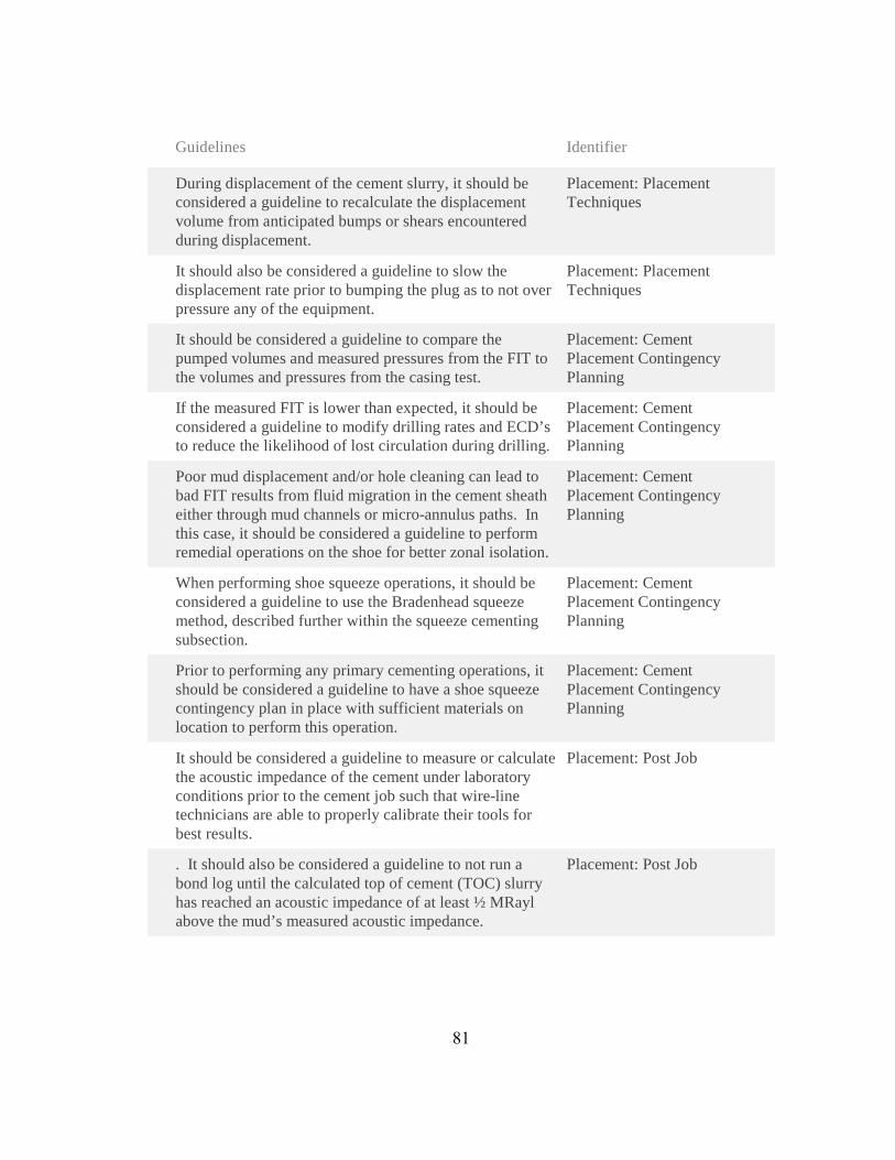
Guidelines Identifier
During displacement of the cement slurry, it should be considered a guideline to recalculate the displacement volume from anticipated bumps or shears encountered during displacement.
Placement: Placement Techniques
It should also be considered a guideline to slow the displacement rate prior to bumping the plug as to not over pressure any of the equipment.
Placement: Placement Techniques
It should be considered a guideline to compare the pumped volumes and measured pressures from the FIT to the volumes and pressures from the casing test.
Placement: Cement Placement Contingency Planning
If the measured FIT is lower than expected, it should be considered a guideline to modify drilling rates and ECD’s to reduce the likelihood of lost circulation during drilling.
Placement: Cement Placement Contingency Planning
Poor mud displacement and/or hole cleaning can lead to bad FIT results from fluid migration in the cement sheath either through mud channels or micro-annulus paths. In this case, it should be considered a guideline to perform remedial operations on the shoe for better zonal isolation.
Placement: Cement Placement Contingency Planning
When performing shoe squeeze operations, it should be considered a guideline to use the Bradenhead squeeze method, described further within the squeeze cementing subsection.
Placement: Cement Placement Contingency Planning
Prior to performing any primary cementing operations, it should be considered a guideline to have a shoe squeeze contingency plan in place with sufficient materials on location to perform this operation.
Placement: Cement Placement Contingency Planning
It should be considered a guideline to measure or calculate the acoustic impedance of the cement under laboratory conditions prior to the cement job such that wire-line technicians are able to properly calibrate their tools for best results.
Placement: Post Job
. It should also be considered a guideline to not run a bond log until the calculated top of cement (TOC) slurry has reached an acoustic impedance of at least ½ MRayl above the mud’s measured acoustic impedance.
Placement: Post Job
81
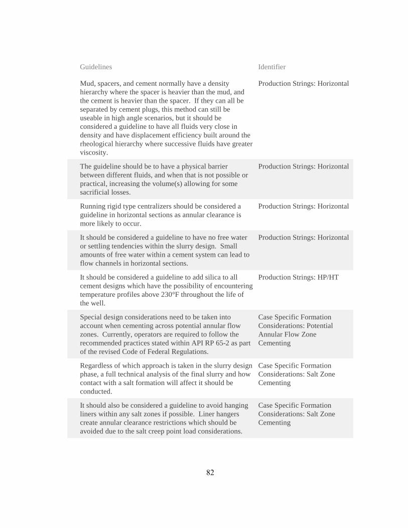
Guidelines Identifier
Mud, spacers, and cement normally have a density hierarchy where the spacer is heavier than the mud, and the cement is heavier than the spacer. If they can all be separated by cement plugs, this method can still be useable in high angle scenarios, but it should be considered a guideline to have all fluids very close in density and have displacement efficiency built around the rheological hierarchy where successive fluids have greater viscosity.
Production Strings: Horizontal
The guideline should be to have a physical barrier between different fluids, and when that is not possible or practical, increasing the volume(s) allowing for some sacrificial losses.
Production Strings: Horizontal
Running rigid type centralizers should be considered a guideline in horizontal sections as annular clearance is more likely to occur.
Production Strings: Horizontal
It should be considered a guideline to have no free water or settling tendencies within the slurry design. Small amounts of free water within a cement system can lead to flow channels in horizontal sections.
Production Strings: Horizontal
It should be considered a guideline to add silica to all cement designs which have the possibility of encountering temperature profiles above 230°F throughout the life of the well.
Production Strings: HP/HT
Special design considerations need to be taken into account when cementing across potential annular flow zones. Currently, operators are required to follow the recommended practices stated within API RP 65-2 as part of the revised Code of Federal Regulations.
Case Specific Formation Considerations: Potential Annular Flow Zone Cementing
Regardless of which approach is taken in the slurry design phase, a full technical analysis of the final slurry and how contact with a salt formation will affect it should be conducted.
Case Specific Formation Considerations: Salt Zone Cementing
It should also be considered a guideline to avoid hanging liners within any salt zones if possible. Liner hangers create annular clearance restrictions which should be avoided due to the salt creep point load considerations.
Case Specific Formation Considerations: Salt Zone Cementing
82

Guidelines Identifier
It should be considered a guideline to use BHA’s that are able to pass LCM through if losses are anticipated.
Case Specific Formation Considerations: Lost Circulation Zone Cementing
It should also be considered a guideline when cementing across known lost circulation zones to have LCM built into the cement design.
Case Specific Formation Considerations: Lost Circulation Zone Cementing
It should be considered a guideline to cure any losses prior to cement placement when possible.
Case Specific Formation Considerations: Lost Circulation Zone Cementing
As a cement placement consideration guideline, pump rates should be increased if losses are encountered during the cement job. Although this statement is counterintuitive, the faster pump rates will ensure better hole cleaning at the shoe.
Case Specific Formation Considerations: Lost Circulation Zone Cementing
There are many recommended guidelines derived from foam cementing case studies which are discussed within the literature review along with documented testing methods discussed within API 10B-4.
Case Specific Formation Considerations: Foam Cementing
There are several additives which as a guideline should be avoided when designing a foam cement system. These additives are: antifoams, dispersants, and potassium chloride.
Case Specific Formation Considerations: Foam Cementing
It should be considered a guideline to have the yield point of the base slurry greater than 10lbf/100ft2.
Case Specific Formation Considerations: Foam Cementing
It should also be considered a best practice to adjust the mixing density of the cement slurry when foaming.
Case Specific Formation Considerations: Foam Cementing
Base slurries with low yield points can also affect the foam quality and foam stability. It should also be considered a guideline to adjust the mixing density of the cement slurry to account for any additives that will be injected downstream of the mixing unit, such as foaming agents and stabilizers.
Case Specific Formation Considerations: Foam Cementing
CSI Technologies makes no representations or warranties, either expressed or implied, and specifically provides the results of this report "as is” based upon the provided information.
83

84
APPENDIX I – TIEBACK CASING PLACEMENT

OperationalGuidelines
Guidelines Identifier
One of the main considerations when discussing the operational guidelines associated with dry cement and additives is documentation and document control.
Dry Cement and Additive Considerations: General Considerations
An operational guideline would be to have a documented chain of custody for all cementing materials arriving on location to be able to easily track lot/batch numbers, chemical manufacture dates, cement QAQC/grind reports, and previous owners/storage locations of the cement and additives.
Dry Cement and Additive Considerations: General Considerations
Record tallies of bulk storage tanks showing a history of cement blends and cleaning operations should also be considered a guideline.
Dry Cement and Additive Considerations: General Considerations
It should be considered a guideline to record the lot numbers of each additive that is dry blended.
Dry Cement and Additive Considerations: Bulk Plant Considerations
All bulk storage tanks should be emptied, cleaned, and inspected regularly. At a minimum, these procedures should be carried out before a new cement blend is placed into the storage tanks. The final quantity and storage tank number should be documented for the blended cement system as well.
Dry Cement and Additive Considerations: Bulk Plant Considerations
Prior to loading or inspecting, the service company should present copies of load tickets to the boat captain and discuss which tanks are to be loaded. Storage tank capacities and hose connections should be verified. After loading, it is recommended to open the tank hatches to verify the amount of cement in each tank.
Dry Cement and Additive Considerations: In Transit Considerations
API RP 65 recommends the use of both top and bottom plugs for all casing cement jobs other than sting-in jobs. The bottom plugs are used as a mechanical separator between fluids while in the casing. Using only two plugs should be considered a minimum guideline. To get the best chances of cementing success, fluid intermixing should be minimized by all means and at all times.
Placement: Cementing Hardware Considerations
85
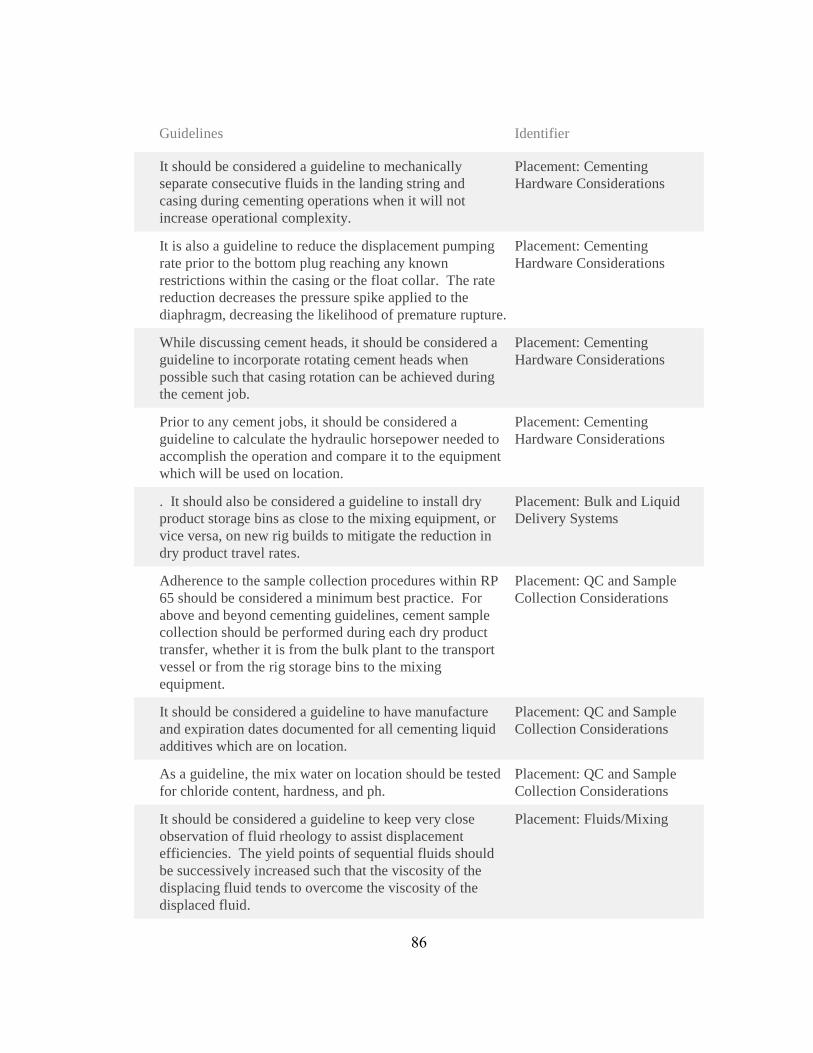
Guidelines Identifier
It should be considered a guideline to mechanically separate consecutive fluids in the landing string and casing during cementing operations when it will not increase operational complexity.
Placement: Cementing Hardware Considerations
It is also a guideline to reduce the displacement pumping rate prior to the bottom plug reaching any known restrictions within the casing or the float collar. The rate reduction decreases the pressure spike applied to the diaphragm, decreasing the likelihood of premature rupture.
Placement: Cementing Hardware Considerations
While discussing cement heads, it should be considered a guideline to incorporate rotating cement heads when possible such that casing rotation can be achieved during the cement job.
Placement: Cementing Hardware Considerations
Prior to any cement jobs, it should be considered a guideline to calculate the hydraulic horsepower needed to accomplish the operation and compare it to the equipment which will be used on location.
Placement: Cementing Hardware Considerations
. It should also be considered a guideline to install dry product storage bins as close to the mixing equipment, or vice versa, on new rig builds to mitigate the reduction in dry product travel rates.
Placement: Bulk and Liquid Delivery Systems
Adherence to the sample collection procedures within RP 65 should be considered a minimum best practice. For above and beyond cementing guidelines, cement sample collection should be performed during each dry product transfer, whether it is from the bulk plant to the transport vessel or from the rig storage bins to the mixing equipment.
Placement: QC and Sample Collection Considerations
It should be considered a guideline to have manufacture and expiration dates documented for all cementing liquid additives which are on location.
Placement: QC and Sample Collection Considerations
As a guideline, the mix water on location should be tested for chloride content, hardness, and ph.
Placement: QC and Sample Collection Considerations
It should be considered a guideline to keep very close observation of fluid rheology to assist displacement efficiencies. The yield points of sequential fluids should be successively increased such that the viscosity of the displacing fluid tends to overcome the viscosity of the displaced fluid.
Placement: Fluids/Mixing
86

Guidelines Identifier
While discussing the importance of laboratory fluid compatibility testing, it should also be considered a guideline to run contaminated thickening time tests to observe how the contamination will vary the cement system’s set time.
Placement: Fluids/Mixing
When using liquid additives for cementing operations on location, it should be considered a guideline to document the storage tank volumes of the additives prior to the cement job for comparison with post job tank volumes.
Placement: Fluids/Mixing
It should be considered a guideline to record the cementing operations which occur on location. As a minimum, the down hole pumping rate, pump pressure and fluid density should be monitored and recorded for all cementing operations.
Placement: Job Recording and Engineering Simulations
Generally, the mix density will fluctuate more than the down hole density, but it still should be a guideline to minimize the mix density fluctuation as much as possible.
Placement: Job Recording and Engineering Simulations
A guideline is to record the fluid returns through flow-meters during the cement job.
Placement: Job Recording and Engineering Simulations
When discussing cement placement simulation software, it should be considered a guideline to have qualified cementing engineers perform the cementing simulations.
Placement: Job Recording and Engineering Simulations
It should be considered a guideline to perform ECD placement simulations assuming gauge hole and hole with excess, assuming average nitrogen injection rate and varied injection rate, taking into account, changes in slurry rheology, foam quality, temperature and pressure during the foam job.
Placement: Job Recording and Engineering Simulations
Prior to cementing operations it should be considered a guideline to have the pipe capacity from the cementing equipment to the rig floor documented. This is generally a fixed volume, but should be a known and used volume for simulation software and for friction pressure
Placement: Placement Techniques
When using the mud pumps for displacement, it should be a guideline to know ahead of time the pump efficiencies for calculation purposes. As a redundancy, flow meters can be installed on the rig pumps for quality assurance.
Placement: Placement Techniques
87

Guidelines Identifier
During displacement of the cement slurry, it should be considered a guideline to recalculate the displacement volume from anticipated bumps or shears encountered during displacement.
Placement: Placement Techniques
It should also be considered a guideline to slow the displacement rate prior to bumping the plug as to not over pressure any of the equipment.
Placement: Placement Techniques
It should be considered a guideline to compare the pumped volumes and measured pressures from the FIT to the volumes and pressures from the casing test.
Placement: Cement Placement Contingency Planning
If the measured FIT is lower than expected, it should be considered a guideline to modify drilling rates and ECD’s to reduce the likelihood of lost circulation during drilling.
Placement: Cement Placement Contingency Planning
Poor mud displacement and/or hole cleaning can lead to bad FIT results from fluid migration in the cement sheath either through mud channels or micro-annulus paths. In this case, it should be considered a guideline to perform remedial operations on the shoe for better zonal isolation.
Placement: Cement Placement Contingency Planning
When performing shoe squeeze operations, it should be considered a guideline to use the Bradenhead squeeze method, described further within the squeeze cementing subsection.
Placement: Cement Placement Contingency Planning
Prior to performing any primary cementing operations, it should be considered a guideline to have a shoe squeeze contingency plan in place with sufficient materials on location to perform this operation.
Placement: Cement Placement Contingency Planning
It should be considered a guideline to measure or calculate the acoustic impedance of the cement under laboratory conditions prior to the cement job such that wire-line technicians are able to properly calibrate their tools for best results.
Placement: Post Job
. It should also be considered a guideline to not run a bond log until the calculated top of cement (TOC) slurry has reached an acoustic impedance of at least ½ MRayl above the mud’s measured acoustic impedance.
Placement: Post Job
It should be considered a guideline to add silica to all cement designs which have the possibility of encountering temperature profiles above 230°F throughout the life of the well.
Production Strings: HP/HT
88

Guidelines Identifier
As an introduction into special formation considerations, it should also be considered a guideline to have the top of cement generally 500ft above salt formations when tiebacks overlap salt zones.
Production Strings: Tieback Liners
It should also be considered a guideline to centralize the tieback casing very well throughout salt zones in anticipation of point loading from salt creep.
Production Strings: Tieback Liners
Special design considerations need to be taken into account when cementing across potential annular flow zones. Currently, operators are required to follow the recommended practices stated within API RP 65-2 as part of the revised Code of Federal Regulations.
Case Specific Formation Considerations: Potential Annular Flow Zone Cementing
Regardless of which approach is taken in the slurry design phase, a full technical analysis of the final slurry and how contact with a salt formation will affect it should be conducted.
Case Specific Formation Considerations: Salt Zone Cementing
It should also be considered a guideline to avoid hanging liners within any salt zones if possible. Liner hangers create annular clearance restrictions which should be avoided due to the salt creep point load considerations.
Case Specific Formation Considerations: Salt Zone Cementing
It should be considered a guideline to use BHA’s that are able to pass LCM through if losses are anticipated.
Case Specific Formation Considerations: Lost Circulation Zone Cementing
It should also be considered a guideline when cementing across known lost circulation zones to have LCM built into the cement design.
Case Specific Formation Considerations: Lost Circulation Zone Cementing
It should be considered a guideline to cure any losses prior to cement placement when possible.
Case Specific Formation Considerations: Lost Circulation Zone Cementing
As a cement placement consideration guideline, pump rates should be increased if losses are encountered during the cement job. Although this statement is counterintuitive, the faster pump rates will ensure better hole cleaning at the shoe.
Case Specific Formation Considerations: Lost Circulation Zone Cementing
There are many recommended guidelines derived from foam cementing case studies which are discussed within the literature review along with documented testing methods discussed within API 10B-4.
Case Specific Formation Considerations: Foam Cementing
89
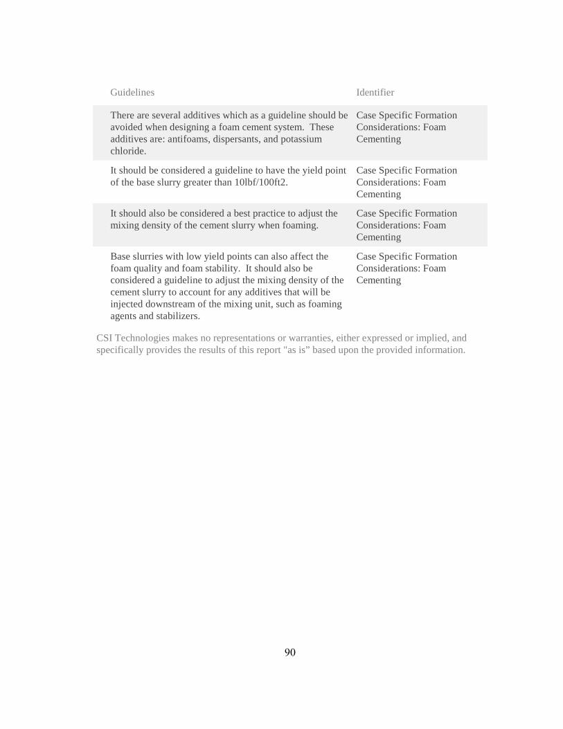
Guidelines Identifier
There are several additives which as a guideline should be avoided when designing a foam cement system. These additives are: antifoams, dispersants, and potassium chloride.
Case Specific Formation Considerations: Foam Cementing
It should be considered a guideline to have the yield point of the base slurry greater than 10lbf/100ft2.
Case Specific Formation Considerations: Foam Cementing
It should also be considered a best practice to adjust the mixing density of the cement slurry when foaming.
Case Specific Formation Considerations: Foam Cementing
Base slurries with low yield points can also affect the foam quality and foam stability. It should also be considered a guideline to adjust the mixing density of the cement slurry to account for any additives that will be injected downstream of the mixing unit, such as foaming agents and stabilizers.
Case Specific Formation Considerations: Foam Cementing
CSI Technologies makes no representations or warranties, either expressed or implied, and specifically provides the results of this report "as is” based upon the provided information.
90

91
APPENDIX J – KICK-OFF REMEDIAL

OperationalGuidelines
Guidelines Identifier
The main guideline for remedial cementing should be to reduce the likelihood of needing to perform remedial cementing through sound placement of previous primary jobs.
Remedial Cementing
When planning on using packers, it should be considered a guideline to take into account the manufactured size restrictions of current packers on the market.
Remedial Cementing: Rig Equipment Considerations
If cement is to be placed using a stinger attached to drill pipe, it should be considered a guideline to have the length of the stinger be twice the calculated length of the longest cement plug which is being set.
Remedial Cementing: Rig Equipment Considerations
Separation of fluids during placement is still considered a guideline. If possible, a foam ball launching manifold should be used to assist with fluid separation.
Remedial Cementing: Rig Equipment Considerations
When performing squeeze operations, it should be considered a guideline to have a squeeze manifold rigged up for the cement job, even if the squeeze procedure does not require one to be rigged up.
Remedial Cementing: Rig Equipment Considerations
It should be considered a guideline to perform abandonment operations with a derrick.
Remedial Cementing: Rig Equipment Considerations
It should be considered a guideline to attach diverter subs onto tubing for placement of any cement plug including: balanced plugs, kick-off plugs, Bradenhead squeeze plugs, etc.
Remedial Cementing: Rig Equipment Considerations
The guideline would be to set the plug across the softest formation when that is possible. Generally the plug needs to be in a strategic position so that the original target depth can be reached with as little disruption as possible.
Remedial Cementing: Cement Kick-Off Plugs
Large diameter holes combined with light low viscosity and low yield point muds, may allow the plug to slump and fall through the mud until it reaches a point where it can be supported or it begins to be self-supporting. The guideline in this situation is to spot a high viscosity mud pill below the plug to help hold the cement in place.
Remedial Cementing: Cement Kick-Off Plugs
92
Guidelines Identifier
Any mud pill or heavier density fluid in the annulus or drill pipe will make accurate placement difficult or impossible as the fluid will u-tube in the pipe until equilibrium is established. The guideline is to circulate and condition the mud until a stable density is achieved.
Remedial Cementing: Cement Kick-Off Plugs
CSI Technologies makes no representations or warranties, either expressed or implied, and specifically provides the results of this report "as is” based upon the provided information.
93

94
APPENDIX K – PLUG REMEDIAL
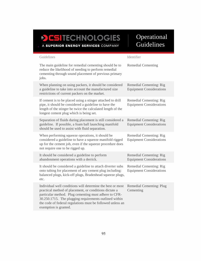
OperationalGuidelines
Guidelines Identifier
The main guideline for remedial cementing should be to reduce the likelihood of needing to perform remedial cementing through sound placement of previous primary jobs.
Remedial Cementing
When planning on using packers, it should be considered a guideline to take into account the manufactured size restrictions of current packers on the market.
Remedial Cementing: Rig Equipment Considerations
If cement is to be placed using a stinger attached to drill pipe, it should be considered a guideline to have the length of the stinger be twice the calculated length of the longest cement plug which is being set.
Remedial Cementing: Rig Equipment Considerations
Separation of fluids during placement is still considered a guideline. If possible, a foam ball launching manifold should be used to assist with fluid separation.
Remedial Cementing: Rig Equipment Considerations
When performing squeeze operations, it should be considered a guideline to have a squeeze manifold rigged up for the cement job, even if the squeeze procedure does not require one to be rigged up.
Remedial Cementing: Rig Equipment Considerations
It should be considered a guideline to perform abandonment operations with a derrick.
Remedial Cementing: Rig Equipment Considerations
It should be considered a guideline to attach diverter subs onto tubing for placement of any cement plug including: balanced plugs, kick-off plugs, Bradenhead squeeze plugs, etc.
Remedial Cementing: Rig Equipment Considerations
Individual well conditions will determine the best or most practical method of placement, or conditions dictate a particular method. Plug cementing must adhere to CFR-30.250.1715. The plugging requirements outlined within the code of federal regulations must be followed unless an exemption is granted.
Remedial Cementing: Plug Cementing
95
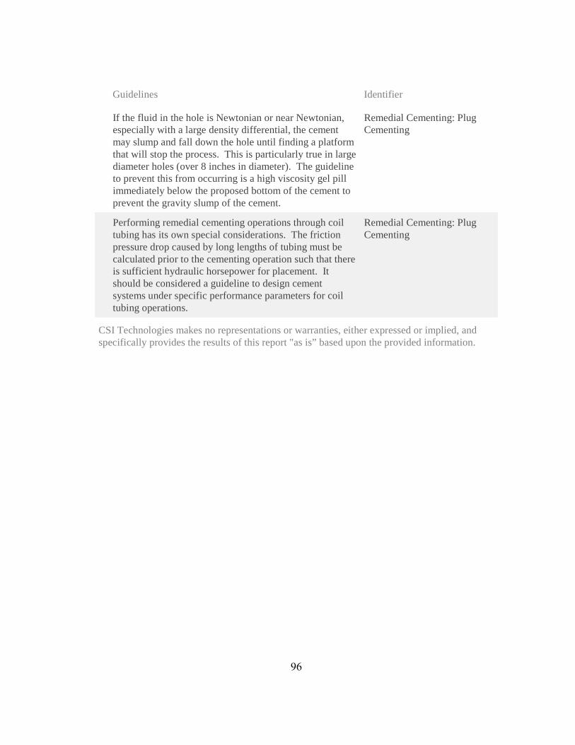
Guidelines Identifier
If the fluid in the hole is Newtonian or near Newtonian, especially with a large density differential, the cement may slump and fall down the hole until finding a platform that will stop the process. This is particularly true in large diameter holes (over 8 inches in diameter). The guideline to prevent this from occurring is a high viscosity gel pill immediately below the proposed bottom of the cement to prevent the gravity slump of the cement.
Remedial Cementing: Plug Cementing
Performing remedial cementing operations through coil tubing has its own special considerations. The friction pressure drop caused by long lengths of tubing must be calculated prior to the cementing operation such that there is sufficient hydraulic horsepower for placement. It should be considered a guideline to design cement systems under specific performance parameters for coil tubing operations.
Remedial Cementing: Plug Cementing
CSI Technologies makes no representations or warranties, either expressed or implied, and specifically provides the results of this report "as is” based upon the provided information.
96

97
APPENDIX L – SQUEEZE REMEDIAL
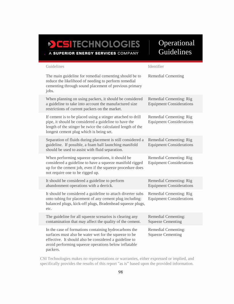
OperationalGuidelines
Guidelines Identifier
The main guideline for remedial cementing should be to reduce the likelihood of needing to perform remedial cementing through sound placement of previous primary jobs.
Remedial Cementing
When planning on using packers, it should be considered a guideline to take into account the manufactured size restrictions of current packers on the market.
Remedial Cementing: Rig Equipment Considerations
If cement is to be placed using a stinger attached to drill pipe, it should be considered a guideline to have the length of the stinger be twice the calculated length of the longest cement plug which is being set.
Remedial Cementing: Rig Equipment Considerations
Separation of fluids during placement is still considered a guideline. If possible, a foam ball launching manifold should be used to assist with fluid separation.
Remedial Cementing: Rig Equipment Considerations
When performing squeeze operations, it should be considered a guideline to have a squeeze manifold rigged up for the cement job, even if the squeeze procedure does not require one to be rigged up.
Remedial Cementing: Rig Equipment Considerations
It should be considered a guideline to perform abandonment operations with a derrick.
Remedial Cementing: Rig Equipment Considerations
It should be considered a guideline to attach diverter subs onto tubing for placement of any cement plug including: balanced plugs, kick-off plugs, Bradenhead squeeze plugs, etc.
Remedial Cementing: Rig Equipment Considerations
The guideline for all squeeze scenarios is clearing any contamination that may affect the quality of the cement.
Remedial Cementing: Squeeze Cementing
In the case of formations containing hydrocarbons the surfaces must also be water wet for the squeeze to be effective. It should also be considered a guideline to avoid performing squeeze operations below inflatable packers.
Remedial Cementing: Squeeze Cementing
CSI Technologies makes no representations or warranties, either expressed or implied, and specifically provides the results of this report "as is” based upon the provided information.
98

99
APPENDIX M – PERFORATION REMEDIAL
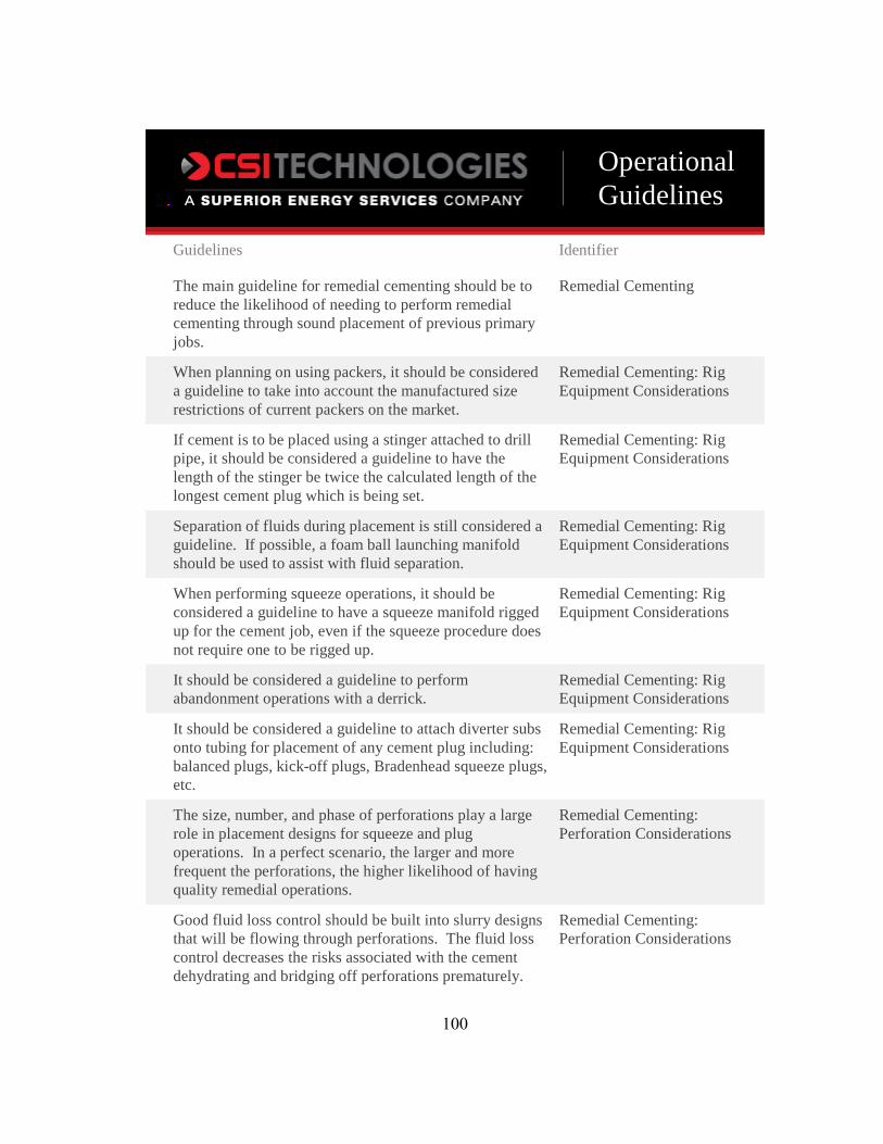
OperationalGuidelines
Guidelines Identifier
The main guideline for remedial cementing should be to reduce the likelihood of needing to perform remedial cementing through sound placement of previous primary jobs.
Remedial Cementing
When planning on using packers, it should be considered a guideline to take into account the manufactured size restrictions of current packers on the market.
Remedial Cementing: Rig Equipment Considerations
If cement is to be placed using a stinger attached to drill pipe, it should be considered a guideline to have the length of the stinger be twice the calculated length of the longest cement plug which is being set.
Remedial Cementing: Rig Equipment Considerations
Separation of fluids during placement is still considered a guideline. If possible, a foam ball launching manifold should be used to assist with fluid separation.
Remedial Cementing: Rig Equipment Considerations
When performing squeeze operations, it should be considered a guideline to have a squeeze manifold rigged up for the cement job, even if the squeeze procedure does not require one to be rigged up.
Remedial Cementing: Rig Equipment Considerations
It should be considered a guideline to perform abandonment operations with a derrick.
Remedial Cementing: Rig Equipment Considerations
It should be considered a guideline to attach diverter subs onto tubing for placement of any cement plug including: balanced plugs, kick-off plugs, Bradenhead squeeze plugs, etc.
Remedial Cementing: Rig Equipment Considerations
The size, number, and phase of perforations play a large role in placement designs for squeeze and plug operations. In a perfect scenario, the larger and more frequent the perforations, the higher likelihood of having quality remedial operations.
Remedial Cementing: Perforation Considerations
Good fluid loss control should be built into slurry designs that will be flowing through perforations. The fluid loss control decreases the risks associated with the cement dehydrating and bridging off perforations prematurely.
Remedial Cementing: Perforation Considerations
100

Guidelines Identifier
CSI Technologies makes no representations or warranties, either expressed or implied, and specifically provides the results of this report "as is” based upon the provided information.
101