development of an antenna tracking electronic system for
TRANSCRIPT

XXXVI SIMPOSIO BRASILEIRO DE TELECOMUNICACOES E PROCESSAMENTO DE SINAIS - SBrT2018, 16-19 DE SETEMBRO DE 2018, CAMPINA GRANDE, PB
Development of an Antenna Tracking ElectronicSystem for Digital Terrestrial TV based on Image
in Real TimeCarlos Alberto Ramirez Behaine and Bernardo Dambros Neckel
Abstract— This development paper intends to assist the evo-lution of digital terrestrial TV signals in Brazil by increasingthe quality of reception in distant areas of large centers. Aimingat this, we illustrate the construction of a cognitive trackingelectronic system in real time, suitable to receive the waves ofthe signals of digital terrestrial TV, by rotations of the spatial axisof an antenna based on image filtering. The antenna used is a log-periodic for the frequencies between 470 MHz and 890 MHz, andthe intelligent electronic used in the automation is based on thenon-coherent analysis of Composite Video Burst Signal (CVBS).The results obtained with the tests of this project prove theireffectiveness, and the importance of the use of an antenna forthe tuning of the digital TV channels in Passo Fundo/RS, as wellas the functionality of the circuits designed for the automationof the antenna.
Keywords— Cognitive receivers, Digital TV receivers, Antennatracking positioning.
I. INTRODUCTION
The digital terrestrial TV transmission in Brazil has beenimplemented gradually since 2007. This evolution is notapplying in all area of Brazil due to several reasons: becauseof the expensive cost of the digital TV broadcast transmitterssystem, the attenuation effect of propagation in extensiveareas and the lack of digital contents on the offer-demandscenario for economic balance. Technically, the level of thedigital TV signals in some distant regions is not sufficient toensure a good quality in the Ultra-High Frequency band (UHF)because of the effect of propagation loss when comparedwith the Very High-Frequency band (VHF) utilized in theold analog TV system. The digital TV modulation schemeis the Coded Orthogonal Frequency Division Multiplexing(COFDM), it has a wide frequency spectrum, which offerscode gain improvements when compared with the basic OFDMscheme. Classical schemes of channel tuning and trackingin receivers operate on high frequency space in order todeterminate optimal level of power, that is acceptable for flatfading, but is not a suitable strategy in very selective channelsas occurring in distant terrestrial regions where the selectivefrequency distortion and attenuation effect are strong even inCOFDM signals, producing unstable images in the receiverthat are not desirable.
There are many strategies in satellite TV receivers toimprove signal quality in signals utilizing tracking of antennas
Carlos Alberto Ramirez Behaine and Bernardo Dambros Neckel¸ ElectricalEngineering, University of Passo Fundo (UPF), Passo Fundo-RS, Brazil, E-mails: [email protected], [email protected].
for satellites based of maximum gain [1], Global PositioningSystem (GPS) aide [2], controlling automated application [3]and multiple selection of parameters: GPS, carrier frequencyand gain using phase look locked (PLL) in high frequency [4],but is not widely utilized for terrestrial TV receivers. A novelsolution for antenna tracking analog terrestrial TV systemwas proposed by analyzing the synchronization condition onComposite Video Burst Signal (CVBS) [5]. The method thatutilizes CVBS shows superiority and effectiveness, however,it was designed and tested for analog TV receiver and needscomplex coherent analysis and synchronization on the image,becoming not suitable for practical implementation for the caseof unstable images in fuzzy space [6].
We propose an antenna tracking electronic system for digitalterrestrial TV based on non-coherent analysis on the image inreal time, that can be approached by simple filtering of CVBSpresent in practical digital TV converters. The core of thisapproach is cognitive in the sense of the filtering of the imagesignal in the baseband. The tests of this project prove theireffectiveness for images that come from digital TV receivers.The proposed implementation is explained step by step in thispaper on the next sections: materials and methods, results andconclusions.
II. MATERIALS AND METHODS
The proposed development is illustrated in a schematicdiagram expressed by four functional blocks as showed in theFig. 1 (a). The fundamental block is the antenna, the secondblock is the digital TV converter receiver where the CVBSis captured, the third block is the signal processing and thefourth block is the mechanical device operator activated by anelectronic power interface. The second block, the digital TVconverter receiver, can be connected to digital standard TVdisplay or monitor by High-Definition Multimedia Interface(HDMI) as illustrated in the Fig. 1 (b).
Fig. 1. Schematic diagram of the proposed development (a) and theconnectivity to standard TV display or monitor (b).

XXXVI SIMPOSIO BRASILEIRO DE TELECOMUNICACOES E PROCESSAMENTO DE SINAIS - SBrT2018, 16-19 DE SETEMBRO DE 2018, CAMPINA GRANDE, PB
A. Antenna Project
An antenna suitable for digital TV signals is the Log-periodic type, which classical project is clearly illustratedin [7] as follows. The frequency spectral band for digitalterrestrial TV in Brazil is in UHF band, specifically between470 MHz and 890 MHz, and then a Log-periodic antennadipole array was projected for this specific band. The Log-periodic antenna was projected for 9 dB of gain, with the αapex half-angle parameter expressed in the Eq. (1)
α = arctan
(1− τ
4σ
)(1)
where σ is the relative spacing and τ is the scale factorparameter. The frequency bandwidth of the project Bs isrelated to
Bs = B(1.1 + 7.7(1− τ)
2cot (α)
)(2)
where B is the ratio frequency of interest. The numbers ofdipoles elements N is calculated as
N = 1 +ln (Bs)
ln (1/τ)(3)
For the specific UHF frequency band desired, B = 890MHz / 470 MHz, σ = 0.171, τ = 0.918, then we utilize theEq. (3) N ≈ 13 dipoles for the array, also considering an inputimpedance of 75 ohms for optimal matching with the digitalTV converter receiver. The antenna was built in the practicewith the dimensions of fabrication in millimeters illustrated inthe Fig. 2 (a), (b), (c), (d) and (e).
Fig. 2. Antenna dimensions in (mm) of the full upper view (a), top upperview (b), bottom upper view (c), side view (d) and front view of basis (e).
B. Digital TV Converter Receiver
Since the antenna bandwidth is addressed to UHF TVchannels, we utilize a standard digital TV converter receivertype intelBras CD636, which has a CVBS output and anHDMI output interface. The CVBS output is a 1D signalcompressed that represent a 2D image. When the RF signalreceived is lack of quality the CVBS is represented by a blackor freeze image during an interval of time. The CVBS can beprocessed in the step C.
C. Signal Processing
The initial stage of processing is to capture the CVBS signalfrom the hardware interface. The shape of CVBS in time isillustrated in the Fig. 3 (a), where the negative level is onlyfor synchronization and positive level represent scales of colorsand luminance. The signal processing in real time proposed isfocused on non-coherent reception based on filtering on DClevel for intervals of time, in order to identify a black image.A full black image in CVBS is represented as minimum DClevel in terms of voltage, and during a persistence of intervalof time, is a characteristic of lack of quality of the image, asillustrated in the Fig. 3 (b). A superior level of voltage duringa window time is identified as a true value of cognitive imagesignal, it is:
Jre = 0 if sa ≤ L (4)
Jre = 1 if sa > sL + L (5)
where sa is the mean of the DC signal filtered during an atime of window analysis, L is a level threshold and sL isthe amplitude of Additive White Gaussian Noise (AWGN)estimated as standard deviation sL =
√σ2n during the zero
signal transmission. Then, Jre = 0 means not cognitive imageand Jre = 1 means a positive candidate for cognitive image.
Fig. 3. CVBS with image information (a) and CVBS with full black imagein term of volts versus time (b).
We project an envelope detector filter with gain for non-coherent analysis considering the discharge time of approx-imately 6 seconds. The envelope detector filter circuit isillustrated in the Fig. 4 (a) and the result of s output signalis illustrated in the Fig. 4 (b) when the DC level is 1.33 V,meaning the value of Jre = 1 with L = 0.5 V and sL = 0.1
XXXVI SIMPOSIO BRASILEIRO DE TELECOMUNICACOES E PROCESSAMENTO DE SINAIS - SBrT2018, 16-19 DE SETEMBRO DE 2018, CAMPINA GRANDE, PB
Fig. 4. Envelope detector filter circuit (a) and s output signal from envelopedetector filter circuit in term of volts versus time (b).
V. The analysis for persistence for the values of Jre = 0 orJre = 1 is done for a window of time higher than a typicalchannel commutation, it is estimated at a = 500 ms.
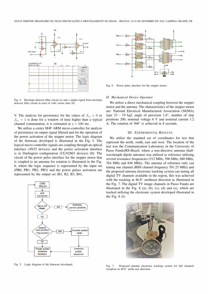
We utilize a cortex M4F ARM micro-controller for analysisof persistence on output signal filtered and for the operation ofthe power activation of the stepper motor. The logic diagramof the firmware developed is illustrated in the Fig. 5. Thelogical micro-controller signals are coupling through an opticalinterface (4N25 devices) and the power activation interfaceis in Darlington configuration (ULN2803 devices) [8]. Thecircuit of the power pulse interface for the stepper motor thatis coupled to an antenna for rotation is illustrated in the Fig.6, where the logic sequence is represented by the input set(PB0, PB1, PB2, PB3) and the power pulses activation arerepresented by the output set (B1, B2, B3, B4).
Fig. 5. Logic diagram of the firmware developed.
Fig. 6. Power pulse interface for the stepper motor.
D. Mechanical Device Operator
We utilize a direct mechanical coupling between the steppermotor and the antenna. The characteristics of the stepper motorare: National Electrical Manufactured Association (NEMA)type 23 - 19 kgf, angle of precision 1.8◦, number of steppositions 200, nominal voltage 6 V and nominal current 1.2A. The rotation of 360◦ is achieved in 8 seconds.
III. EXPERIMENTAL RESULTS
We utilize the standard set of coordinates for test thatrepresent the north, south, east and west. The location of thetest was the Communication Laboratory in the University ofPasso Fundo/RS-Brazil, where a non-directive antenna (half-wavelength dipole antenna) was utilized as reference utilizingseveral resonance frequencies (512 MHz, 596 MHz, 680 MHz,764 MHz and 848 MHz). The antenna of reference only cantuning one channel (RBS channel frequency 591.25 MHz) andthe proposed antenna electronic tracking system can tuning alldigital TV channels available in the region, this was achievedwith the tracking at 46.8◦ northeast direction as illustrated inthe Fig. 7. The digital TV image channels in Passo Fundo areillustrated in the Fig. 8 (a), (b), (c), (d) and (e), which aretracked utilizing the electronic system developed illustrated inthe Fig. 8 (f).
Fig. 7. Proposed antenna electronic tracking system for full channelsreception in 46.8◦ north east direction.

XXXVI SIMPOSIO BRASILEIRO DE TELECOMUNICACOES E PROCESSAMENTO DE SINAIS - SBrT2018, 16-19 DE SETEMBRO DE 2018, CAMPINA GRANDE, PB
A comparative test was done for the half-wavelength dipoleantenna without tracking positioning (as reference) and theproposed antenna tracking electronic system, in two envi-ronments of receptions: laboratory outdoor and laboratoryindoor. The comparative results, in terms of a number ofimage channels tuned, are illustrated in the Tab. I. Such resultssuggest that the proposed antenna tracking electronic systemachieve a better performance in term of the number of imagechannels tuned (5 and 5) than the reference (1 and 0).
Fig. 8. Digital TV image channels: RBS (a), BAND (b), Record (c), RedeVida (d), SBT (e), tracked utilizing the electronic system developed in (f).
TABLE ICOMPARATIVE RESULTS.
Location Feature Half-wavelengthdipoleantennawithouttracking
Proposedantennatrackingelectronicsystem
LaboratoryOutdoor
Numberofimagechannelstuned
1 5
LaboratoryIndoor
Numberofimagechannelstuned
0 5
IV. CONCLUSIONS
The proposed antenna tracking electronic system was de-veloped considering signals in the UHF spectrum for digitalTV signals through a suitable antenna, also it was developedanalyzing CVBS with cognitive meaning utilizing filteringin baseband. The results obtained with the tests of thisproject, suggest the effectiveness of an antenna with cognitiveelectronic positioning capabilities in real time, for digital TVchannels in Passo Fundo/RS-Brazil.
ACKNOWLEDGEMENTS
The authors would like to thank the Laboratory of Commu-nication (LACOM) and the Laboratory of Electronic Mainte-nance of the University of Passo Fundo (UPF) / RS- Brazil.
REFERENCES
[1] A. Gonzales, R. Ayala, T. Mendez, and R. Rodriguez, “Control Systemfor the antenna positioning,” 7th WSEAS international conference onapplied informatics and communication. pp 390–392, August 2007.
[2] M. Kim, J. Kim, and O. Yan, “Precise attitude control system designfor the tracking of parabolic satellite antenna,” International Journal ofSmart Home, August 2013.
[3] R. S. Anggara, H. Wijanto, D. Prasetyo, and B. Syihabuddin, “Auto-mated Ground Station with Customized Rotator for Antenna Pointingusing Compass Sensor,” IEEE International Conference on ElectricalEngineering and Computer Science, November 2014.
[4] A. S. de Jesus et al., “Sistema Automatico de Apontamento de Antenapara Receptores Satelitais nas Bandas C e Ku,” XXXV SimposioBrasileiro de Telecomunicacoes e Processamento de Sinais – SBrT2017,pp. 186–190, setembro de 2017.
[5] H. Miawarni and E. Setijadi, “Antenna tracking system based on pulseof synchronization CVBS: Design System And Analyze,” 2016 Inter-national Electronics Symposium (IES), Denpasar, pp. 228–233, 2016.
[6] H. Miawarni, M. Mahaputra Hidayat, S. Sumpeno and E. Setijadi, “Real-time video quality assessment based on fuzzy inference system foranalog television tracking antenna system,” 2017 International Seminaron Intelligent Technology and Its Application (ISITIA), Surabaya, pp.35–40, 2017.
[7] C. A. Balanis, “Antenna Theory: Analysis and Design,” 3rd Edition,Hoboken, NJ: John Wiley, 2005.
[8] F. J. Arnold et al., “Amplificadores com transistores bipolaresna configuracao Darlington para pequenos sinais,” Divisao deTelecomunicacoes, Faculdade de Tecnologia, Universidade Estadual deCampinas. Marco 2014.