development of a wireless inter-robot communication system for
TRANSCRIPT

DEVELOPMENT OF A WIRELESS INTER-ROBOT COMMUNICATION SYSTEM FOR GREENHOUSE OPERATIONS
Yi-Chich Chiu, Pen-Yuan Yang, Tony E. Grift
1 Professor, Dept. of Biomechatronic Engineering, National Ilan University, Taiwan
2 Graduate Student, Dept. of Biomechatronic Engineering, National Ilan University, Taiwan 3 Associate Professor, Dept. of Agricultural and Biological Engineering, University of Illinois, USA
ABSTRACT The objectives of this study were to 1) develop a wireless system enabling inter-robot communication and 2) to demonstrate operations using the system in a model of a greenhouse. The developed wireless control system can be applied in the task assignment in multiple robots in fruit picking, pesticide spraying, resource transportation, etc. Graphical programming software LabVIEW® 8.6 was employed to develop the monitoring and remote system in combination with Zigbee® wireless communication technology. The initial work status for each robot can be set through a human-machine interface. To verify and demonstrate the communication, four Parallax Boe-Bot robots were used among which two are the working-robots (Robot-Y1 and Robot-Y2) moving in greenhouse working row (Y-direction). The other two are assist-robots (named as Robot-X1 and Robot-X2) moving in greenhouse passage way (X-direction) to assist the working-robots in changing working rows. PBASIC was used to program the movement of the robots. The results showed that the developed wireless control system works well. The supervisor can monitor the status of each robot and observe working information such as which working rows are finished, how many working rows have been processed, etc. The experimental results showed that the success rate of system operation in different operating conditions can maintain above 95%. Therefore, the developed wireless control system has shown potential application in real life greenhouse operations. Keywords: Automation, Robotic, Transportation, Remote. INTRODUCTION Wireless sensor networking technologies have been widely applied in communication, controls, and environmental monitoring. Many wireless sensor networks have been developed such as Bluetooth, ZigBee, EnOcean, TransferJet, etc. ZigBee, based on the IEEE 802.15.4-2003 standard for wireless personal area networks (WPANs), features a low-cost, low-power, wireless machine to machine (M2M) mesh networking proprietary standard, and easily installation and maintenance. The low cost allows the technology to be widely deployed in wireless control and monitoring applications, the low power-usage allows longer life with smaller batteries, and the mesh networking provides high reliability and larger range. It is simpler and less expensive than other WPANs, such as Bluetooth. ZigBee is targeted at radio-frequency (RF) applications that require a low data rate, long battery life, and secure networking, which is a specification for a suite of high level communication protocols using small, low-power digital radios (Wikipedia, 2010). Many articles reveals ZigBee wireless sensor networks (WSNs) have a potential to be applied in the development of control and monitoring system in the field of agriculture and biology, such as a wireless programmable electronic platform for implantable monitoring of blood glucose level (Valdastri et al., 2009); the vineyard environment monitoring system in precision viticulture (Morais et al., 2008); the irrigation and fertilizer controller of plant (Coates and Delwiche, 2009); the crop canopy temperature monitoring system (O'Shaughnessy and Evett, 2010); a monitoring system for the herd motion behavior (Nadimi et al., 2008); the online monitoring of cows’ presence and pasture time in an extended area covered by a strip of new grass (Nadimi, et al., 2008); a real-time monitoring system for precision horticulture (Riquelme, et al., 2009); monitoring system for body temperature of dairy cows (Ipema et al., 2008); monitoring and modeling silage temperature (Green et al., 2009). O'Shaughnessy and Evett (2010) constructed wireless sensor networks for monitoring crop canopy temperature using a moving sprinkler system as a platform, which sensor nodes mounted on masts
fixed to the lateral arm of a center pivot irrigation system functioned to monitor crop canopy temperatures while the system moved. Greenhouse production advantages a high-quality and high-productivity in vegetable and fruit cultivation but it is labor-intensive and higher investment. Greenhouses require long hours of work, hazardous activities, and repetitive tasks, such as harvesting, spraying, and pruning. These circumstances decrease operational efficiency and could harm the operator's health (Gonzlez et al. 2009). Thus, automatization in greenhouse production is important issue in recent years, especially for internal transport of resources and plants, spraying and crop harvesting task. Some researchers focused on the development of the robotic systems for specific task in greenhouse industries, such as Singh et al., 2005 developed an autonomous robotic vehicle for greenhouse spraying, which spraying system was mounted on a pull-behind trailer that was towed down the aisle. Gonzlez et al. (2009) designed a mobile robot moving autonomously between lines of crop in greenhouses, which robot provides a platform to equip implements on it to perform some tasks, such as spraying, pruning, and crop transport. Van Henten et al. (2003) developed an autonomous harvesting robot for greenhouse cucumbers, and a manipulator was designed and analyzed for this cucumber harvesting robot (Van Henten et al., 2009). Van Henten et al. (2006) also developed an autonomous robot for de-leafing cucumber plants grown in a high-wire cultivation system in greenhouse. In Japan, Shiigi et al.(2008) developed a strawberry harvesting robot for fruits grown on table top culture in greenhouse, which picking robot consists of a suction head connected to a blower and tow fingers could hold on fruit by suction head and cut and grasp peduncle by two fingers rotate according to peduncle inclination. Kondo et al. (2007; 2008) studied in tomato cluster harvesting by a robot in Dutch style greenhouses, including the technologies of image processing, design of the manipulator and end-effector. Crop production in greenhouse is labor intensive and working frequently in the various operations, such as resources inner transportation, harvesting, spraying, growth management, etc. Therefore, application of automatic robotic system in greenhouse industry is a trend in the future. It advantages to save the labor usage, increase the working efficiency and do those monotonous works instead of workers. It is worthy to develop an inter-communicated system between the central control unit and the working robotic systems in greenhouse using a wireless sensor network technology. The inter-communicated system can be applied not only monitor the working status of the robotic systems, but also assign a specific task for each robot. Thus, the objectives of this study were to 1) develop a wireless system enabling inter-robot communication and 2) to demonstrate operations using the system in a model of a greenhouse. The developed wireless control system can be applied in the task assignment in multiple robots in fruit picking, pesticide spraying, resource transportation, etc. SYSTEM DESCRIPTIONS The wireless inter-robot communication system was developed by graphical programming software LabVIEW® 8.6 cooperated with Zigbee® wireless communication technology. To verify and demonstrate the function of inter-communicated system, the commercial Boe-Bot robots (Parallax, Boe-Bot robot kit USB version) were used as the robots working in greenhouse. The scale-down greenhouse was made to demonstrate the inter-robots operations. Figure 1 shows the structure diagram of the wireless inter-robot communication system. Detail information of the system described as follows.

LabVIEW® 8.6Zigbee chip
Digi XBee-PRO XBP24
StrvomotorParallax Continuous
Rotation Servo
MicrocontrollerBASIC Stamp 2
Moudle
Zigbee chipDigi XBee-PRO
XBP24
Infrared detector of path tracing
PBASICBASIC Stamp Editor Version
2.4.2
StrvomotorParallax Continuous
Rotation Servo
MicrocontrollerBASIC Stamp 2
Moudle
Zigbee chipDigi XBee-PRO
XBP24
Infrared detector of path tracing
PBASICBASIC Stamp Editor Version
2.4.2
Mounting platform
Wireless control system of multiple greenhouse inter-robots
communication
Robot-X1/Robot-X2 Robot-Y1/Robot-Y2 PC-Based central unit
Figure 1. The Structure diagram of the wireless inter-robot communication system
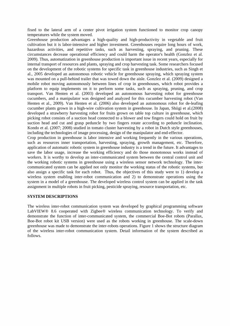
2.1 Robots working pattern Four commercial Boe-Bot robots were used as the inter-robots. Two of four are working-robots (called as Robot-Y1 and Robot-Y2) that move in a greenhouse working lane (Y-direction). The working-robots represent to fulfill the specific assignment such as picking fruits, spraying the plants, transporting the relative resources in lane between plants or plant-benches. After the working-robots finish a row work, they need to move to the next working row. It is complicate and expansive to design a turnable moving vehicle for each working-robot to have the function of moving to the next lane by itself, especially in a narrow passage way located on the end of aisle of greenhouse. It is a way more practical to design another robotic vehicle to pick the working-robot up and move the working-robot to next working lane. Therefore, in our developed system, two assist-robots (called as Robot-X1 and Robot-X2) moving in these two passage ways (X-direction), respectively, located on the both sides of greenhouse were designed to help the working-robots changing the working lanes(Fig. 2). In this study, SolidWorks® was used to design the system including the model of the greenhouse, working-robots, assist-robots and the mounting-platforms of the robots (Fig. 3). An animation system has also been developed in SolidWorks® to observe and evaluate the movement of greenhouse inter-robots and to demonstrate and optimize the performance.
Figure 2. Planning diagram of inter-robots movements in greenhouse
(a). Working-robot
(b). Working-robot moves onto the assist-robot
Figure 3. Design of working-robots and assist-robots
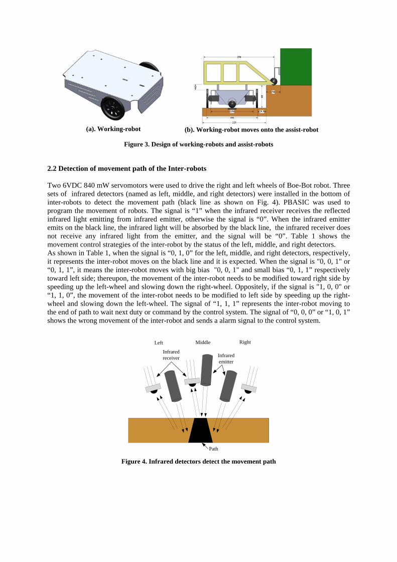
2.2 Detection of movement path of the Inter-robots Two 6VDC 840 mW servomotors were used to drive the right and left wheels of Boe-Bot robot. Three sets of infrared detectors (named as left, middle, and right detectors) were installed in the bottom of inter-robots to detect the movement path (black line as shown on Fig. 4). PBASIC was used to program the movement of robots. The signal is “1” when the infrared receiver receives the reflected infrared light emitting from infrared emitter, otherwise the signal is “0”. When the infrared emitter emits on the black line, the infrared light will be absorbed by the black line, the infrared receiver does not receive any infrared light from the emitter, and the signal will be “0”. Table 1 shows the movement control strategies of the inter-robot by the status of the left, middle, and right detectors. As shown in Table 1, when the signal is “0, 1, 0” for the left, middle, and right detectors, respectively, it represents the inter-robot moves on the black line and it is expected. When the signal is "0, 0, 1" or “0, 1, 1”, it means the inter-robot moves with big bias "0, 0, 1" and small bias “0, 1, 1” respectively toward left side; thereupon, the movement of the inter-robot needs to be modified toward right side by speeding up the left-wheel and slowing down the right-wheel. Oppositely, if the signal is "1, 0, 0" or “1, 1, 0”, the movement of the inter-robot needs to be modified to left side by speeding up the right-wheel and slowing down the left-wheel. The signal of “1, 1, 1” represents the inter-robot moving to the end of path to wait next duty or command by the control system. The signal of “0, 0, 0” or “1, 0, 1” shows the wrong movement of the inter-robot and sends a alarm signal to the control system.
Left Right
Infrared emitter
Infrared receiver
Middle
Path
Figure 4. Infrared detectors detect the movement path

Table 1. the movement control strategies of the inter-robot by the status of the left, middle, and right infrared detectors
Signal of infrared detectors Left Middle Right
Status of robot movement Policies
0 1 0 Normal moving Keep moving 0 0 1 A big bias movement toward the left
side Make a major movement toward right side
0 1 1 A small bias movement toward the left side
Make a minor movement toward right side
1 0 0 A big bias movement toward the right side
Make a major movement toward left side
1 1 0 A small bias movement toward the right side
Make a minor movement toward left side
1 1 1 Stop sign detection Stop 1 0 1 Wrong movement Display “Error” and replace
the robot on the correct position
0 0 0 Wrong movement Display “Error” and replace the robot on the correct position
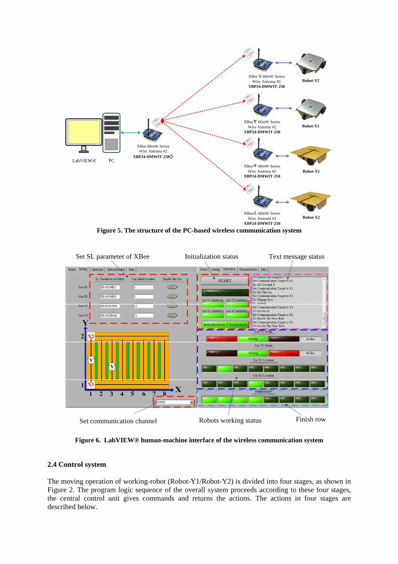
2.3 Structure of the wireless communication system A PC-based central control unit was developed using the graphical programming language LabVIEW® version 8.6, which unit communicates with the four inter-robots through a Zigbee® wireless network. The XBee-PRO DigiMesh® 2.4 operates on the IEEE 802.15.4 physical radio specification and the embedded RF modules utilize the peer-to-peer DigiMesh protocol in 2.4 GHz for global deployments. The RF data rate is 250 kbps and the maximum serial data rate is 115.2 kbps. The communication range reaches about 100m in indoors and 1500m in outdoors environments with a 63mW of Transmit Power at a working voltage of 3V. Figure 5 shows the structure of the wireless communication system. It can be observed in this Figure 5 that these four inter-robots do not communicate with each other; the inter-robots just communicate with central control unit through Zigbee® to receive the assigned task and to report the working status. Thus, the central control unit needs to plan the sequence of task execution by these inter-robots and to allocate the tasks to each inter-robot. Consequently, this control methodology can simplify the control program for each inter-robot and reduce the control elements of the inter-robots. The program of the central control unit consists of two parts: the block diagram represents the logical and sequential processes; the human-machine interface panel inputs the setting parameters, controls inter-robot movements and displays the status of inter-robots operations. Figure 6 demonstrates the LabVIEW® human-machine interface of the wireless communication system.
Robot-X1
Robot-Y1
Robot-X2
Robot-Y2
XBee 60mW SeriesWire Antenna #2
XBP24-DMWIT-250
XBee 60mW SeriesWire Antenna #2
XBP24-DMWIT-250
XBee 60mW SeriesWire Antenna #2
XBP24-DMWIT-250
XBee 60mW SeriesWire Antenna #2
XBP24-DMWIT-250
XBee 60mW SeriesWire Antenna #2
XBP24-DMWIT-250LabVIEW PC
Figure 5. The structure of the PC-based wireless communication system
Set SL parameter of XBee Initialization status Text message status
Set communication channel Robots working status Finish row
Figure 6. LabVIEW® human-machine interface of the wireless communication system
2.4 Control system The moving operation of working-robot (Robot-Y1/Robot-Y2) is divided into four stages, as shown in Figure 2. The program logic sequence of the overall system proceeds according to these four stages, the central control unit gives commands and returns the actions. The actions in four stages are described below.
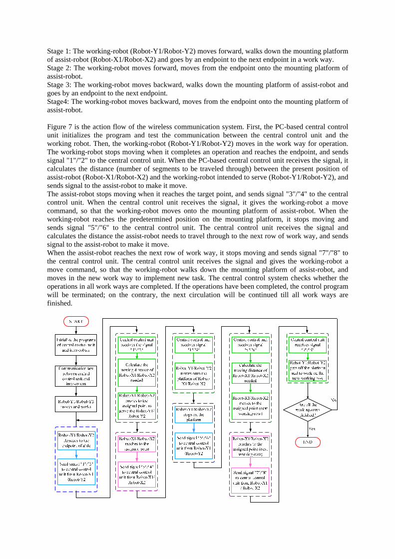
Stage 1: The working-robot (Robot-Y1/Robot-Y2) moves forward, walks down the mounting platform of assist-robot (Robot-X1/Robot-X2) and goes by an endpoint to the next endpoint in a work way. Stage 2: The working-robot moves forward, moves from the endpoint onto the mounting platform of assist-robot. Stage 3: The working-robot moves backward, walks down the mounting platform of assist-robot and goes by an endpoint to the next endpoint. Stage4: The working-robot moves backward, moves from the endpoint onto the mounting platform of assist-robot. Figure 7 is the action flow of the wireless communication system. First, the PC-based central control unit initializes the program and test the communication between the central control unit and the working robot. Then, the working-robot (Robot-Y1/Robot-Y2) moves in the work way for operation. The working-robot stops moving when it completes an operation and reaches the endpoint, and sends signal "1"/"2" to the central control unit. When the PC-based central control unit receives the signal, it calculates the distance (number of segments to be traveled through) between the present position of assist-robot (Robot-X1/Robot-X2) and the working-robot intended to serve (Robot-Y1/Robot-Y2), and sends signal to the assist-robot to make it move. The assist-robot stops moving when it reaches the target point, and sends signal "3"/"4" to the central control unit. When the central control unit receives the signal, it gives the working-robot a move command, so that the working-robot moves onto the mounting platform of assist-robot. When the working-robot reaches the predetermined position on the mounting platform, it stops moving and sends signal "5"/"6" to the central control unit. The central control unit receives the signal and calculates the distance the assist-robot needs to travel through to the next row of work way, and sends signal to the assist-robot to make it move. When the assist-robot reaches the next row of work way, it stops moving and sends signal "7"/"8" to the central control unit. The central control unit receives the signal and gives the working-robot a move command, so that the working-robot walks down the mounting platform of assist-robot, and moves in the new work way to implement new task. The central control system checks whether the operations in all work ways are completed. If the operations have been completed, the control program will be terminated; on the contrary, the next circulation will be continued till all work ways are finished.
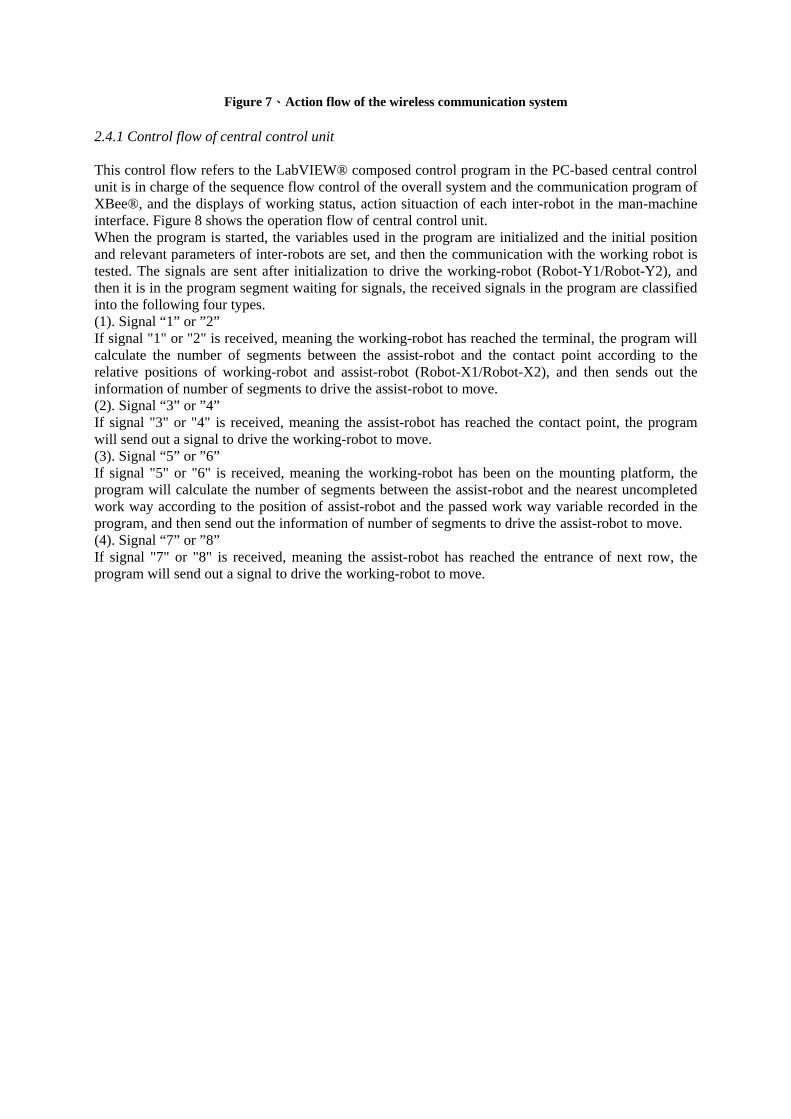
Figure 7、Action flow of the wireless communication system 2.4.1 Control flow of central control unit This control flow refers to the LabVIEW® composed control program in the PC-based central control unit is in charge of the sequence flow control of the overall system and the communication program of XBee®, and the displays of working status, action situaction of each inter-robot in the man-machine interface. Figure 8 shows the operation flow of central control unit. When the program is started, the variables used in the program are initialized and the initial position and relevant parameters of inter-robots are set, and then the communication with the working robot is tested. The signals are sent after initialization to drive the working-robot (Robot-Y1/Robot-Y2), and then it is in the program segment waiting for signals, the received signals in the program are classified into the following four types. (1). Signal “1” or ”2” If signal "1" or "2" is received, meaning the working-robot has reached the terminal, the program will calculate the number of segments between the assist-robot and the contact point according to the relative positions of working-robot and assist-robot (Robot-X1/Robot-X2), and then sends out the information of number of segments to drive the assist-robot to move. (2). Signal “3” or ”4” If signal "3" or "4" is received, meaning the assist-robot has reached the contact point, the program will send out a signal to drive the working-robot to move. (3). Signal “5” or ”6” If signal "5" or "6" is received, meaning the working-robot has been on the mounting platform, the program will calculate the number of segments between the assist-robot and the nearest uncompleted work way according to the position of assist-robot and the passed work way variable recorded in the program, and then send out the information of number of segments to drive the assist-robot to move. (4). Signal “7” or ”8” If signal "7" or "8" is received, meaning the assist-robot has reached the entrance of next row, the program will send out a signal to drive the working-robot to move.
START
Initialize the program
Communicate test Between PC-baced
central unit andinter-robots
Start Robot-Y1 and Robot-Y2 to move
Does receive theSignals frominter-robot?
Get the signal "1" and "2"
Calculate the moving segments
of Robot-X1/Robot-X2 neededd
Start the Robot-x1/Robot-X2 moving
to the assigned point to serve the Robot-Y1/Robot-
Y2
Are all the working-rows
finished?END Yes
receive theSignals
No
Signal "1" or "2"
Get the signal "3" and "4"
Start Robot-Y1/Robot-Y2 moving on the platform of Robot-X1/Robot-
X2
Signal "3" or "4"
Get the signal "5" and "6"
Calculate the moving segments
of Robot-X1/Robot-X2 neededd
Start the Robot-x1/Robot-X2 moving
to the assigned point(next working-
row)
Signal "5" or "6"
Get the signal "7" and "8"
Start Robot-Y1/Robot-Y2 getting off the platform
Signal "7" or "8"
Yes
No
Figure 8. The operation flow of PC-based central control unit
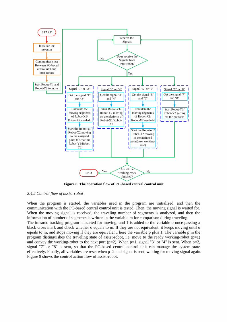
2.4.2 Control flow of assist-robot When the program is started, the variables used in the program are initialized, and then the communication with the PC-based central control unit is tested. Then, the moving signal is waited for. When the moving signal is received, the traveling number of segments is analyzed, and then the information of number of segments is written in the variable m for comparison during traveling. The infrared tracking program is started for moving, and 1 is added to the variable o once passing a black cross mark and check whether o equals to m. If they are not equivalent, it keeps moving until o equals to m, and stops moving if they are equivalent, here the variable p plus 1. The variable p in the program distinguishes the traveling state of assist-robot, i.e. move to the ready working-robot (p=1) and convey the working-robot to the next port (p=2). When p=1, signal "3" or "4" is sent. When p=2, signal "7" or "8" is sent, so that the PC-based central control unit can manage the system state effectively. Finally, all variables are reset when p=2 and signal is sent, waiting for moving signal again. Figure 9 shows the control action flow of assist-robot.
START
Initialize the program
Communication test with PC-based
central control unit
Wait for the moving signal and the
traveling number of segments
Does the moving signal
receive ?
Analyze the traveling number of
segments
Start the infrared tracking program
Add 1 to the variable o once
passing a black cross mark
Write the traveling number of segments into the variable m
o = m ?
Stop and the variable p plus 1
Sent signal “3” or “4”
p =1 ?
Sent signal"7" or "8"
Reset all the variables
No
YesYes
No
Yes
No
Figure 9. The control action flow of assist-robot
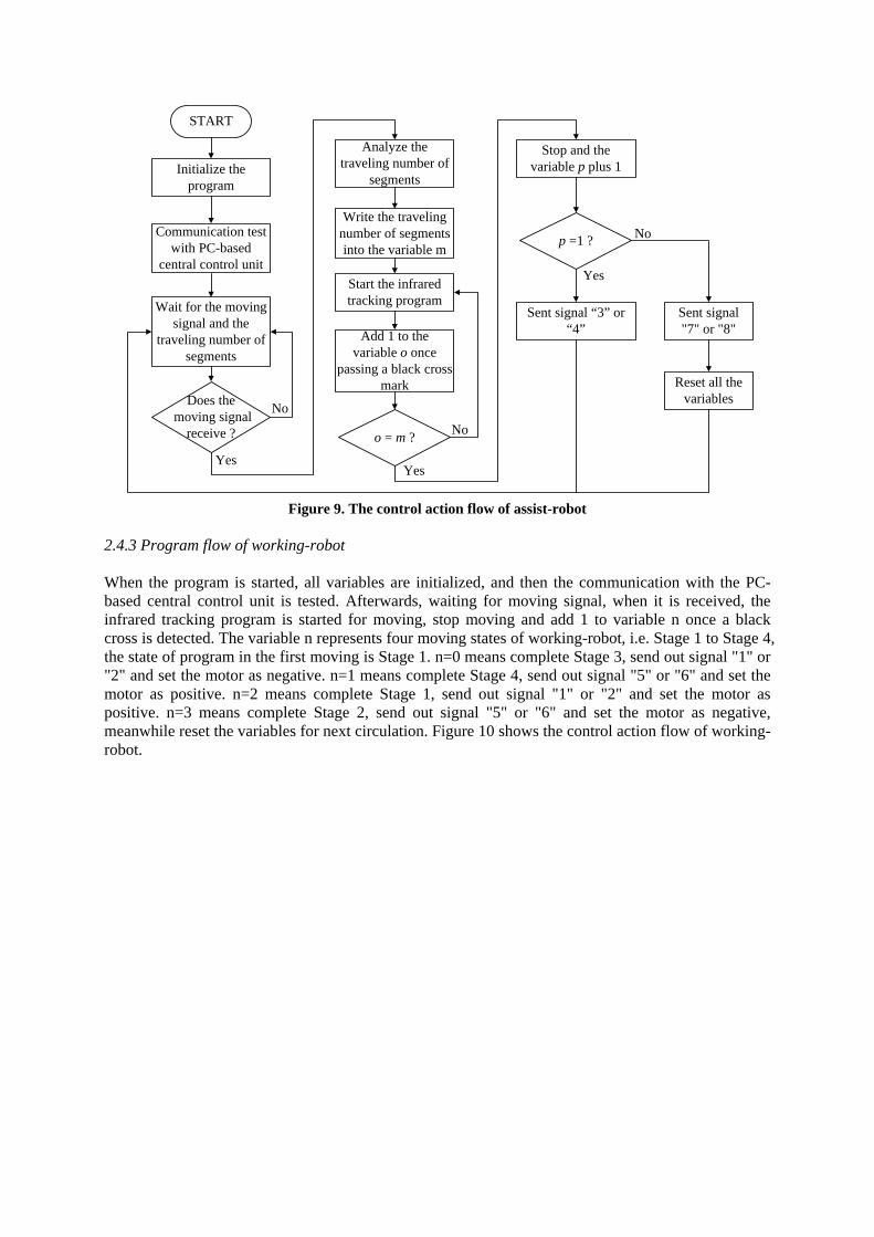
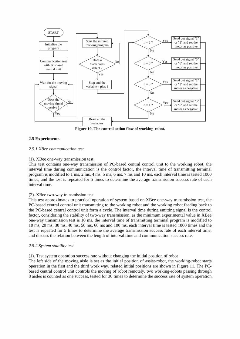
2.4.3 Program flow of working-robot When the program is started, all variables are initialized, and then the communication with the PC-based central control unit is tested. Afterwards, waiting for moving signal, when it is received, the infrared tracking program is started for moving, stop moving and add 1 to variable n once a black cross is detected. The variable n represents four moving states of working-robot, i.e. Stage 1 to Stage 4, the state of program in the first moving is Stage 1. n=0 means complete Stage 3, send out signal "1" or "2" and set the motor as negative. n=1 means complete Stage 4, send out signal "5" or "6" and set the motor as positive. n=2 means complete Stage 1, send out signal "1" or "2" and set the motor as positive. n=3 means complete Stage 2, send out signal "5" or "6" and set the motor as negative, meanwhile reset the variables for next circulation. Figure 10 shows the control action flow of working-robot.
START
Initialize the program
Communication test with PC-based
central unit
Wait for the moving signal
Does themoving signal
receive ?
Start the infrared tracking program
Stop and the variable n plus 1
Does ablack cross
detect ?
n = 2 ?
n = 0 ?
n = 3 ?
n = 1 ?
Send out signal "1" or "2" and set the motor as positive
Send out signal "5" or "6" and set the motor as negative
Send out signal "5" or "6" and set the motor as positive
Send out signal "1" or "2" and set the motor as negative
Reset all the variables
Yes
No
Yes
No
Yes
No
Yes
No
Yes
NoYes
No
Figure 10. The control action flow of working-robot.
2.5 Experiments 2.5.1 XBee communication test (1). XBee one-way transmission test This test contains one-way transmission of PC-based central control unit to the working robot, the interval time during communication is the control factor, the interval time of transmitting terminal program is modified to 1 ms, 2 ms, 4 ms, 5 ms, 6 ms, 7 ms and 10 ms, each interval time is tested 1000 times, and the test is repeated for 5 times to determine the average transmission success rate of each interval time. (2). XBee two-way transmission test This test approximates to practical operation of system based on XBee one-way transmission test, the PC-based central control unit transmitting to the working robot and the working robot feeding back to the PC-based central control unit form a cycle. The interval time during emitting signal is the control factor, considering the stability of two-way transmission, as the minimum experimental value in XBee one-way transmission test is 10 ms, the interval time of transmitting terminal program is modified to 10 ms, 20 ms, 30 ms, 40 ms, 50 ms, 60 ms and 100 ms, each interval time is tested 1000 times and the test is repeated for 5 times to determine the average transmission success rate of each interval time, and discuss the relation between the length of interval time and communication success rate. 2.5.2 System stability test (1). Test system operation success rate without changing the initial position of robot The left side of the moving aisle is set as the initial position of assist-robot, the working-robot starts operation in the first and the third work way, related initial positions are shown in Figure 11. The PC-based central control unit controls the moving of robot remotely, two working-robots passing through 8 aisles is counted as one success, tested for 30 times to determine the success rate of system operation.
Robot-X2
Aisle 1
Aisle 8
Robot-Y1
Robot-Y1
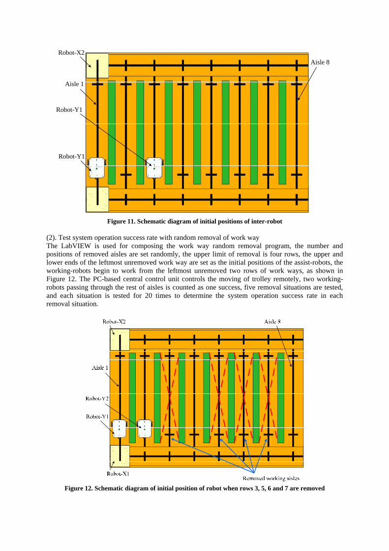
Figure 11. Schematic diagram of initial positions of inter-robot
(2). Test system operation success rate with random removal of work way The LabVIEW is used for composing the work way random removal program, the number and positions of removed aisles are set randomly, the upper limit of removal is four rows, the upper and lower ends of the leftmost unremoved work way are set as the initial positions of the assist-robots, the working-robots begin to work from the leftmost unremoved two rows of work ways, as shown in Figure 12. The PC-based central control unit controls the moving of trolley remotely, two working-robots passing through the rest of aisles is counted as one success, five removal situations are tested, and each situation is tested for 20 times to determine the system operation success rate in each removal situation.
Figure 12. Schematic diagram of initial position of robot when rows 3, 5, 6 and 7 are removed

2.5.3 Discussion about operation time of working-robots in different initial positions The operation time for working-robots to complete 8 rows from different initial positions is tested, and the initial positions of four working-robots are set by the LabVIEW composed random number program. Five groups of initial positions are tested, each group is tested for 5 times to calculate the mean required time of five groups of positions for comparison. 3. RESULTS AND DISCUSSION 3.1. Animation and demonstration SolidWorks® was used to design the system including the model of the greenhouse, working-robots, assist-robots and the mounting-platforms of the robots. An animation system has also been developed in SolidWorks® to observe and evaluate the movement of greenhouse inter-robots and to demonstrate and optimize the performance (Fig. 13). The model of the greenhouse was made from Medium Density Fiber board with a dimensions of 2465mm by 1765mm (Fig. 14). The results showed that the wireless control system works well; The supervisor can monitor the working status of all the robots and observe working information such as which row is finished, how many working rows are completed, etc. The developed wireless control system can be applied in the task assignment among multiple robots in greenhouse operations, such as in fruit picking, pesticide application, internal transport, etc.
Figure 13. System and dynamic simulation diagram drawn by SolidWorks®
Figure 14. Practical operation of system

3.2 Experimental results of XBee communication 3.2.1 Test result of XBee one-way transmission Figure 15 shows the result of XBee one-way transmission test. According to the curve in Figure 15, when the one-way transmission interval time is less than 4ms, the transmission success rate is lower than 20%, which is to say, the working-robot cannot receive signal successfully because the transmission interval time is too short. The movement command can be received effectively when the transmission interval time is greater than 5ms. When the transmission interval time is greater than 7 ms, 100% transmission success rate can be obtained.
0
20
40
60
80
100
0 1 2 3 4 5 6 7 8 9 10
Transmission interval time, ms
Succ
ess r
ate,
%
Figure 15 Relation between interval time of one-way transmission and success rate
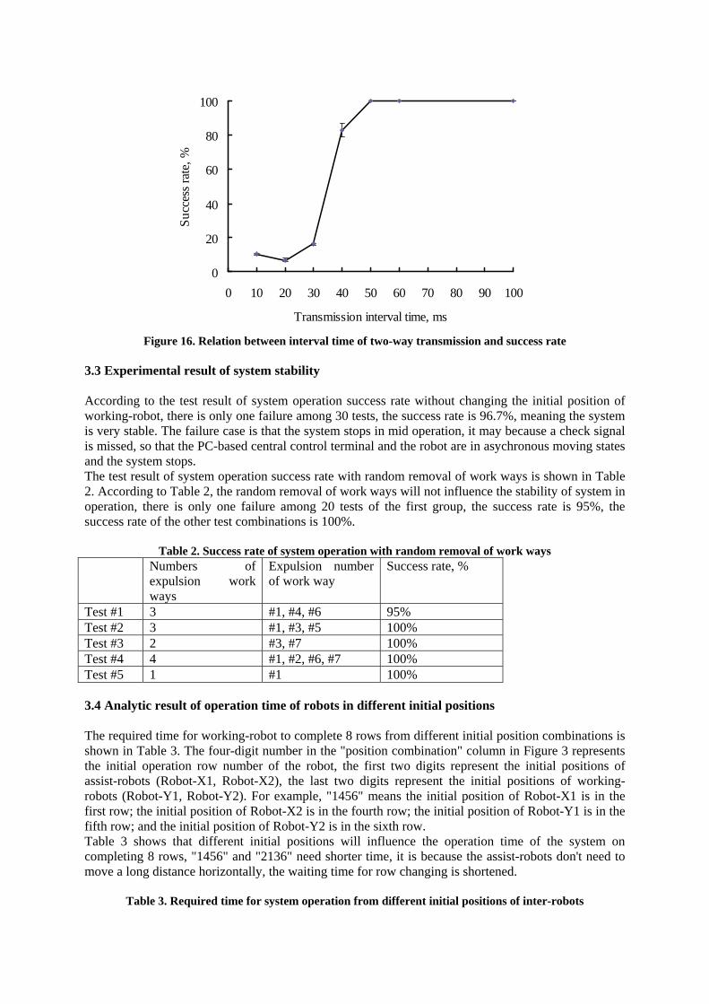
3.2.2 Experimental result of XBee two-way transmission Figure 16 shows the result of XBee two-way transmission test. According to Figure 16, when the tracking interval time of two-way transmission is less than 30ms, the transmission success rate is lower than 20%, which is to say, the working-robot cannot receive signal because the transmission interval time is too short. When the transmission interval time is greater than 50 ms, 100% transmission success rate can be obtained. In addition, the test result shows that the interval time is greater than one-way transmission, because Xbee output and input share the channel, if the interval time is too short, failure is likely to happen as a result of output communication data colliding with input communication data. Therefore, the Xbee sends back signal to the central control system until the previous signal is processed, so the time is longer than one-way transmission time. According to the test result, the interval time of system wireless transmission can be set as above 50 ms.
0
20
40
60
80
100
0 10 20 30 40 50 60 70 80 90 100
Transmission interval time, ms
Succ
ess r
ate,
%
Figure 16. Relation between interval time of two-way transmission and success rate
3.3 Experimental result of system stability According to the test result of system operation success rate without changing the initial position of working-robot, there is only one failure among 30 tests, the success rate is 96.7%, meaning the system is very stable. The failure case is that the system stops in mid operation, it may because a check signal is missed, so that the PC-based central control terminal and the robot are in asychronous moving states and the system stops. The test result of system operation success rate with random removal of work ways is shown in Table 2. According to Table 2, the random removal of work ways will not influence the stability of system in operation, there is only one failure among 20 tests of the first group, the success rate is 95%, the success rate of the other test combinations is 100%.
Table 2. Success rate of system operation with random removal of work ways Numbers of
expulsion work ways
Expulsion number of work way
Success rate, %
Test #1 3 #1, #4, #6 95% Test #2 3 #1, #3, #5 100% Test #3 2 #3, #7 100% Test #4 4 #1, #2, #6, #7 100% Test #5 1 #1 100% 3.4 Analytic result of operation time of robots in different initial positions The required time for working-robot to complete 8 rows from different initial position combinations is shown in Table 3. The four-digit number in the "position combination" column in Figure 3 represents the initial operation row number of the robot, the first two digits represent the initial positions of assist-robots (Robot-X1, Robot-X2), the last two digits represent the initial positions of working-robots (Robot-Y1, Robot-Y2). For example, "1456" means the initial position of Robot-X1 is in the first row; the initial position of Robot-X2 is in the fourth row; the initial position of Robot-Y1 is in the fifth row; and the initial position of Robot-Y2 is in the sixth row. Table 3 shows that different initial positions will influence the operation time of the system on completing 8 rows, "1456" and "2136" need shorter time, it is because the assist-robots don't need to move a long distance horizontally, the waiting time for row changing is shortened.
Table 3. Required time for system operation from different initial positions of inter-robots

Initial positon row number of Robot-X1, Robot-X2, Robot-Y1, and Robot-Y2
1456 4672 2536 2774 2136 Test #1, s 180 186 187 183 172 Test #2, s 170 187 186 175 171 Test #3, s 172 196 180 177 181 Test #4, s 173 182 192 184 179 Test #5, s 177 181 181 181 174 Avg.± Std. dev.
174.4±4.04 186.4±5.94 185.2±4.87 180.0±3.87 175.4±4.39
4. CONCLUSIONS The wireless monitoring system developed by this study has good system operation stability in practice. The success rate of system operation in different operating conditions can maintain above 95%. The administrator can monitor the working state of each robot through the man-machine interface composed by LabVIEW, and check the real-time work information, such as the number of finished work ways and which work way has been finished. The wireless monitoring system developed by this study can be applied to practical greenhouse operation in the future, such as fruit picking, pesticide spraying operation and multi-robot cooperation or teaching, so that the students can learn about the technologies related to wireless communications and multi-robot cooperation. The developed system is useful as a teaching-aid so that the students can learn aspects of the wireless communication and the application of multiple robots systems (MRS) in a greenhouse. In future work, end-effectors can be mounted on the robots to mimic actual robotic operation systems in greenhouses. Acknowledgements The authors wish to acknowledge the financial support given to this project by National Science Council, Republic of China (NSC 98-2918-I-197-001). We would also like to extend our thanks to professor C. Ay and professor A. P. Chen for their helpful suggestions, and Ms. Y. H. Chang and Mr. G. H. Chen for their assistance. References: Coates, R. W., Delwiche, M. J. (2009). Wireless mesh network for irrigation control and sensing Transactions of the ASABE. 52(3): 971-981. Gonzlez, R., Rodrguez, F., nchez-Hermosilla, J. S., Donaire, J. G. (2009). Navigation techniques for mobile robots in greenhouses Applied Engineering in Agriculture. 25(2): 153-165. Green, O., Nadimi, E. S., Blanes-Vida, V., Jørgensen, R. N., Storm, I. M. L. D., Sørensen, C. G. (2009). Monitoring and modeling temperature variations inside silage stacks using novel wireless sensor networks Computers and Electronics in Agriculture. 69(2): 149-157. Ipema, A. H., Goense, D., Hogewerf, P. H., Houwers, H. W. J., Roest, H. (2008). Pilot study to monitor body temperature of dairy cows with a rumen bolus Computers and Electronics in Agriculture. 64(1): 49-52. Kondo, N., Taniwaki, S., Tanihara, K., Yata, K., Monta, M., Kurita, M., Tsutumi, M. (2007). An end-effector and manipulator control for tomato cluster harvesting robot 2007 ASABE Annual International Meeting, Paper No: 073144. Minneapolis, Minnesota, USA. Kondo, N., Yamamoto, K., Yata, K., Kurita, M. (2008). A machine vision for tomato cluster harvesting robot 2008 ASABE Annual International Meeting, Paper No: 084044. Providence, Rhode Island, USA. Morais, R., Fernandes, M. A., Matos, S. G., Serodio, C., Ferreira, P.J.S.G., Reis, M.J.C.S. (2008). A ZigBee multi-powered wireless acquisition device for remote sensing applications in precision viticulture Computers and Electronics in Agriculture 62(2): 94-106.

Nadimi, E.S., Søgaard, H.T., Bak, T. (2008). ZigBee-based wireless sensor networks for classifying the behaviour of a herd of animals using classification trees Biosystems Engineering. 100: 167-176. Nadimi, E.S., Søgaard, H.T., Bak, T., Oudshoorn, F.W. (2008). ZigBee-based wireless sensor networks for monitoring animal presence and pasture time in a strip of new grass Computers and Electronics in Agriculture. 61(2): 79–87. O'Shaughnessy, S. A., Evett, S. R. (2010). Developing wireless Sensor networks for monitoring crop canopy temperature using a moving sprinkler system as a platform Applied Engineering in Agriculture. 26(2): 331-341. Riquelme, J. A. L., Soto, F., Suardíaz, J., Sánchez, P., Iborra, A., Vera, J. A. (2009). Wireless sensor networks for precision horticulture in Southern Spain Computers and Electronics in Agriculture. 68(1): 25-35. Shiigi, T., Kurita, M., Kondo, N., Ninomiya, K., Rajendra, P., Kamata, J., Hayashi, S., Kobayashi, K., Shigematsu, K., Kohno, Y. (2008). Strawberry harvesting robot for fruits grown on table top culture 2008 ASABE Annual International Meeting, Paper No: 084046. Providence, Rhode Island, USA. Singh, S., Burks, T. F., Lee, W. S. (2005). Autonomous robotic vehicle development for greenhouse spraying Transactions of the ASAE. 48(6): 2355-2361. Valdastri, P., Susilo, E., Förster, T., Strohhöfer, C., Menciassi, A., Dario, P.(2009). Wireless implantable electronic platform for blood glucose level monitoring Proceedings of the Eurosensors XXIII conference--Procedia Chemistry. 1: 1255-1258. Van Henten, E. J., Van Tuijl, B. A. J., Hemming, J., Kornet, J. G., Bontsema, J., Van Os, E. A. (2003). Field test of an autonomous cucumber picking robot Biosystems Engineering. 86 (3): 305–313. Van Henten, E. J., Van Tuijl, B. A. J., Hoogakker, G. J., Van Der Weerd, M. J., Hemming, J., Kornet, J. G., Bontsema, J. (2006). An autonomous robot for de-leafing cucumber plants grown in a high-wire cultivation system Biosystems Engineering. 94 (3): 317–323. Van Henten, E. J., Van’t Slot, D. A., Hol, C. W. J., Van Willigenburg, L. G. (2009). Optimal manipulator design for a cucumber harvesting robot Computers and Electronics in Agriculture. 65(2): 247-257. Wikipedia. 2010. Zigbee. Available at: http://en.wikipedia.org/wiki/Zigbee.