development of a guidelines document for … • growing number of cable-stayed bridges •...
TRANSCRIPT

Development of a Guidelines Document for Aerodynamic Design of Stay Cables
J. Jerry ShenLENDIS Corporation
Turner-Fairbank Highway Research Center
Harold BoschOffice of Infrastructures R&D
Federal Highway Administration

Outlines
• Background– Motivation– Objectives
• Introduction to current work– Outline of Work– Primary References– Scope
• Significant Issues– Performance requirements– Hazard definition– Vibration mechanisms– Design/Analysis– Mitigation– Testing
• Summary– Impact to the industry– Future studies

Motivation
• Growing number of cable-stayed bridges• Insufficient design provisions for dynamic wind
hazard• FHWA’s practical orientation on research• Academic communication→engineer’s language
– Interpretation of existing knowledge from various types of industry
– Identifying and resolving technical issues in conveying research products to practice
• Abundant results from pooled fund study since1999—SPR-3(078)

Objectives
• Making use of available research products– Tailoring the practices in various industry (bridge, building,
power transmission, offshore structure,…) into suitable forms for stay cables
– Identifying missing connections among research products that impede their implementation
– Developing practical resolution to bridge the identified gaps when possible
– Proposing necessary studies• Developing design procedures that fit into state-of-the-art
design and retrofitting methodology• Implementing simple and cost-effective aerodynamic
hazard mitigation design schemes• Clarifying technical terms

Outline of work
• Reviewing available materials• Producing scalable documental framework and
identifying essential needs for further studies• Consulting committee• Developing details of procedures and drafting the
document• Reviewing
•Revising•Re-reviewing•Publishing
•Publishing•Preparation for second edition
or
Currentprogress
Primary References
• Wind Induced Vibration of Stay Cables (HNTB)
• Draft-Guidelines for Design and Retrofit (Buckland & Taylor)
• Recommendations for Stay Cable Design, Testing and Installation (PTI Guide Spec)
• AASHTO and other design guides

Scope:The guidance document includes:
• Performance requirements• Hazard definition• Structural/component response and analysis
– Structural force and deflection• LRFD design and mitigation methods
– Limit states– Load factors and resistance factors– Selection of mitigation methods and recommended
design procedures• Testing

Scope:The document does not include:
• Detailed derivation• Untested or rare mitigation methods• Hybrid mitigation (may be included in the
future)• Design example (will be developed upon
completion)

Some significant issues
• Performance requirements• Hazard definition• Identification of vibration mechanisms• Design and Analysis:
– Strength ∝ resilience– Stress in cables from dynamic response
• Mitigation:– Composing practical design scheme with available
analysis methods
• Testing
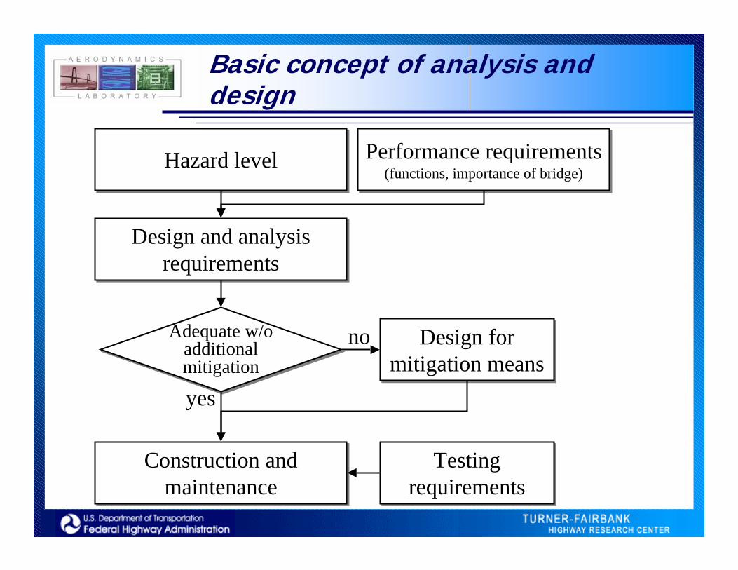
Basic concept of analysis and design
Hazard levelHazard level Performance requirements(functions, importance of bridge)
Performance requirements(functions, importance of bridge)
Design and analysis requirements
Design and analysis requirements
Design for mitigation means
Design for mitigation means
Testing requirements
Testing requirements
Construction and maintenance
Construction and maintenance
Adequate w/o additional mitigation
Adequate w/o additional mitigation
no
yes

Performance requirements
• Using LRFD: a risk-based approach, and can be made performance-based
• Aerodynamics related limit states• New extreme limit state• Performance requirements for extreme limit
state• Assessment of performance

Aerodynamic-related limit states
• Strength V– Strength III: High wind, low traffic; Strength V:
moderate wind, normal traffic– WS in strength V should be modified to reflect
the possible maximum response under moderate wind
• Service I– Normal operational condition– Deflection control and user comfort

Aerodynamic-related limit states
• Fatigue– Only concern oscillatory load
• Extreme limit states– AASHTO only includes earthquake and
ice/collision/hydraulic extreme event– Aerodynamic extreme event may not only occur
at or above design wind speed– Concurrent with static wind load– Multi-level performance requirements

Load and resistance factors inPTI guide spec and AASHTO bridge design
Limit state Resistance factor (PTI 5.3.3)
Strength 0.65
Service 0.85
Fatigue 1
Extreme event 1
Limit state Load factor (AASHTO static—WS)
Strength 0.4
Service 0.3
Fatigue 1.05
Extreme event 1
Construction 1.25
Also AASHTO 6.5.5 for steel members
0.75 (by AASHTO)×1.4 (by PTI 5.1.3 for long-span bridges)Should be raised
Value 1.0 same as other hazard. To be combined with Extreme II of AASHTO
By AASHTO 3.4.2

Possible approach:A new multi-level extreme limit state
• Multi-level performance-based design• Combination with loads in normal operation• Check on fatigue, service, and strength
concerns• Consistent with seismic design but address
static and dynamic wind issues

Concerns in aerodynamic extreme event
Wind level Concerns Performance objectives
Moderate w
ind
Fatigue
Stress produced by vibration is below the level of which the cables and other affected components may develop fatigue crack or fracture in the service life of the bridge.
Service
The vibration amplitude does not produce visual irritation or rattling noise. Vibration level of the vehicular traffic lanes and sidewalk/bikeway remain the comfortable and safe range for respective usage. Corrosion resistant layers must remain uncracked. Visible movement or damage of cosmetic attachments and coatings should be controlled.
Strength
Force effects on structural component must be in the adequate range and no yielding and rupture occur. Vibration control devices or fuse devices that are designed to yield or break under extreme wind speed may be allowed to be activated for lower level storm.
Lower level storm
Minimal and repairable damage occurs.
Upper level storm InstabilityStructural failure is prevented under upper level wind storm or loss of cable due to wind or other hazards.

Wind hazard definition
• Design map values: 50 yr fastest-mile (AASHTO) or 3-sec gust (ASCE 7)
• Lower level wind storm: 100 yr return period• Upper level wind storm: 10,000 yr return
period• Aerodynamic response sometimes peaks at
moderate wind speed. The current hazard map does not provide sufficient information on such events.

Sample wind speed distribution of 15 yrs record
Vandiver et al, 1996
0
100
200
300
400
500
600
0 5 10 15 20 25 30 35 40
m/s
Even
ts
NNNENEENEEESESESSESSSWSWWSWWWNWNWNNW
0
0.2
0.4
0.6
0.8
1
1.2
0 5 10 15 20 25 30 35 40
m/s
Rat
io o
f exc
eeda
nce
Wind speed distribution
Wind speed and ratio of exceedance

Wind level and probability Of exceedance
Wind level Probability of exceedance in 75 years
Moderate wind (often occurrence)
To be determined
Lower level storm (Service) 53%
Upper level storm (Life safety) 0.75%

Local hazard level
• AASHTO: ASCE-7(88) map, fastest-mile wind @30 ft above ground
• Logarithm profile above ground• Exposure category• Map is equivalent to 50-yr event. Data of
return period below 50 yrs (moderate wind) is not available.
• Rain data may be needed
0
300 ln5.2
ZZ
VVVV
BDZ =

Identified Mechanisms
• SPR-3(078) report (HNTB)– Vortex– Rain/wind induced– Wake Galloping– Inclined Galloping– Ice Accumulation Galloping– System Vibration– Buffeting– Cable Tension Fluctuation
• PTI guide spec– Buffeting– Vortex Shedding in
wake– Self-induction
(galloping)– Wake Galloping– Wind-rain interaction
Considered significant

Mechanisms by AASHTO LRFD
• Vortex Shedding• Galloping—not considered for circular
sections• Flutter• Divergence

Identification of vibration mechanisms
• Is it necessary or possible to distinguish vibration mechanisms by engineering practitioners?
• General design criteria may be found to cover most vibration episodes
• Identifying mechanisms may be more important in problem-driven retrofitting

Analysis: Design and analysis procedures
Obtain structural design parameters
BeginningDesign
Performance objectivesHazard definition
Determine design requirements
Check structural
performance
Unacceptable
Acceptable
Enddesign
Modify designAerodynamic
performance
Feasible for mitigation
Unacceptable
AcceptableNo
Yes
Design for mitigation
BeginningRetrofit design
Obtain structural dynamic properties
Hazard definition
Design for rain-wind interaction
Design for galloping
Design for vortex shedding
Determine retrofit category
Determine service life
Determine performance category
Enddesign

Key parameters for response computation
• Length• Axial tension• Linear mass density• Axial and flexural stiffness• Anchorage• Frequency (combined effect of above parameters)• Shape and surface features• Damping• Cables in group

Analysis: Factors in performance and stress profile
• Functional and mechanical performance• Analysis model (e.g. taut string vs. beam)• Equivalent sectional property (section
modulus, bending stiffness vs. tension, grouting)
• Boundary conditions (fixity, initial rotation)• Sag-extensibility• Transverse bracing (guide-pipe bushing,
damper)

Analysis: Response and stress
Distributedloading profile (from dynamic response build-up)
Shear force profile
Shear force from cable tension (P-Δeffect)
Shear force from shear stress in each section
Inflection points
Bending moment
Zero moment
Small positive moment
stay cable

Mitigation methods
• Aerodynamic mitigation– Aerodynamic properties by testing
• Mechanical mitigation– Damper design for multiple modes
• Structural mitigation– Design procedure for cross-ties
• Hybrid mitigation– Insufficient data
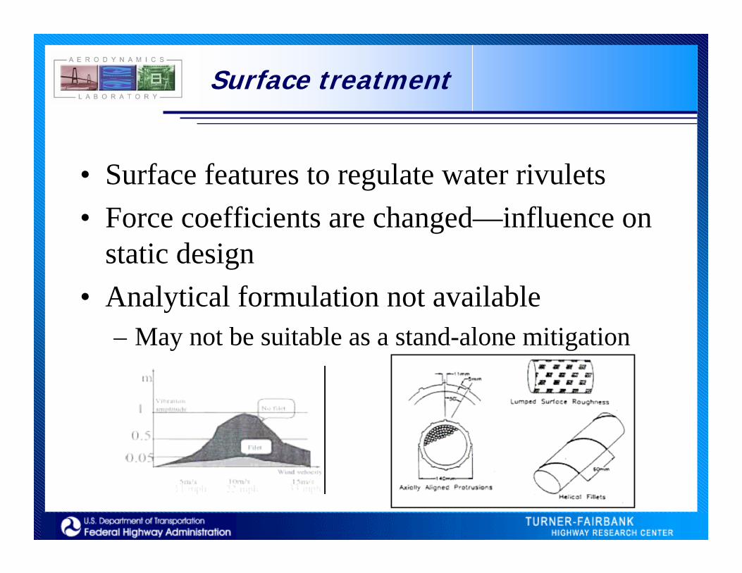
Surface treatment
• Surface features to regulate water rivulets• Force coefficients are changed—influence on
static design• Analytical formulation not available
– May not be suitable as a stand-alone mitigation

Ll1ξ
κκA0 κB0
κA0 > 5 κB0
0.42 %)2.1( 1 =Ll
0.25 %)2( 1 =Ll
κA1 κB1
κA1 < 5 κB1
κ1 κ2 κ3 κ4 κ5
Damper design
• Choice of the type of damper• Choice of damper location• Inherent damping in
cables• Calculation of
damping coefficient• Damper-induced
stress

Cross-tie design
• Choice of the number of cross-tie• Calculation of the size of the cross-tie• Straightforward design procedure (spread
sheet approach)• Amount of post-tensioning
Bill Emerson Memorial Bridge, MO XTieConneYTieConneXTieConneYTieConnect2-94.20667 44.95 -47.98333 69.77
X2, Y2 -12.32317 22.95 -24.57663 45.77Cable# Xtower Ytower Xdeck Ydeck Tension CableFreq xTieAnchoryTieAnchorTargetFreqX1 Y1 #ofCrossTi Lumda
1 -1.76 94.59 -140.43 20.13 4537 0.557289 -81.8835 22 1.381788 -138.67 -74.46 -94.20667 44.95 -47.98333 69.77 2 2.5965062 -1.76 93.07 -136.77 20.26 4759 0.585754 -23.4067 24 RefFreq -135.01 -72.81 -93.48388 43.60392 -47.30549 68.50762 2 2.4703273 -1.76 91.54 -133.12 20.39 4537 0.593401 2.786447 -131.36 -71.15 -92.75785 42.25181 -46.62456 67.2395 2 2.4384934 -1.76 90.02 -129.47 20.53 4359 0.713216 -127.71 -69.49 -92.03236 40.90069 -45.94665 65.97701 2 2.0288465 -1.76 88.49 -125.93 20.6 4163 0.721553 -124.17 -67.89 -91.29883 39.53461 -45.26337 64.70451 2 2.0054046 -1.75 86.98 -115.38 20.98 4011 0.768935 -113.63 -66 -89.42935 36.05298 -44.03608 62.41887 2 1.881837 -1.73 85.48 -104.83 21.35 3801 0.811754 -103.1 -64.13 -87.36705 32.21226 -42.72628 59.9796 2 1.7825668 -1.72 83.97 -94.27 21.74 3682 0.870701 -92.55 -62.23 -85.06671 27.92823 -41.31314 57.34784 2 1.6618859 -1.73 82.46 -83.79 22.09 3272 1.047998 -82.06 -60.37 -82.458 23.06992 -39.77027 54.47449 1 2.071098
10 -1.71 80.97 -73.26 22.48 2992 1.117443 -71.55 -58.49 -79.43204 17.43454 -38.04715 51.26546 1 1.94238711 -1.71 79.48 -62.74 22.86 2832 1.22414 -61.03 -56.62 -75.82627 10.71934 -36.07699 47.59636 1 1.77308812 -1.82 77.88 -52.22 23.27 2631 1.340842 -50.4 -54.61 -71.40399 2.483534 -33.75683 43.27543 1 1.61876513 -1.84 76.05 -41.79 23.59 2498 1.578532 -39.95 -52.46 -65.80457 -7.944528 -30.87955 37.91697 1 1.37501714 -1.84 73.98 -31.3 23.99 2061 1.655355 -29.46 -49.99 -58.32668 -21.87095 -27.16707 31.00308 1 1.31120415 -2.35 70.38 -20.85 24.37 1821 1.851166 -18.5 -46.01 -47.52867 -41.98058 -22.02981 21.43577 1 1.17250816 -2.37 65.08 -10.41 24.81 1692 2.177226 -8.04 -40.27 -30.19131 -74.26875 -14.05053 6.57565 1 0.996914
E2.00E+08 2.00E+08
Ct L Lc1 Lc2 A1 A2 D1 D20.073681 52.4655 26.04924 51.95098 1.53E-04 3.05E-04 1.53E-04 3.05E-04 1.40E-02 1.97E-020.098119 51.13055 24.52138 50.51812 1.16E-04 2.40E-04 2.69E-04 5.45E-04 1.85E-02 2.63E-020.104985 49.79711 22.98667 49.07875 9.98E-05 2.13E-04 3.69E-04 7.58E-04 2.17E-02 3.11E-020.234601 48.46385 21.4531 47.64576 4.11E-05 9.14E-05 4.10E-04 8.49E-04 2.29E-02 3.29E-020.245531 47.17254 19.90253 46.20142 3.58E-05 8.31E-05 4.46E-04 9.32E-04 2.38E-02 3.45E-020.313817 43.8023 15.95074 43.60712 2.33E-05 6.37E-05 4.69E-04 9.96E-04 2.44E-02 3.56E-020.386134 40.47258 11.59136 40.83843 1.41E-05 4.97E-05 4.83E-04 1.05E-03 2.48E-02 3.65E-020.506996 37.17537 6.7288 37.85127 6.58E-06 3.70E-05 4.90E-04 1.08E-03 2.50E-02 3.71E-020.441595 50.93717 1.214411 34.5899 8.84E-07 2.52E-05 4.91E-04 1.11E-03 2.50E-02 3.76E-020.660556 46.20737 5.181996 30.94751 2.54E-06 1.52E-05 4.93E-04 1.12E-03 2.51E-02 3.78E-021.374932 41.62477 12.80404 26.78291 3.17E-06 6.63E-06 4.97E-04 1.13E-03 2.51E-02 3.79E-026.434273 37.15647 22.15203 21.87847 1.22E-06 1.20E-06 4.98E-04 1.13E-03 2.52E-02 3.79E-02
-1.833561 32.96989 33.98833 15.79637 -7.03E-06 -3.27E-06 4.91E-04 1.13E-03 2.50E-02 3.79E-02-1.435805 29.01246 49.79542 7.948802 -1.23E-05 -1.97E-06 4.78E-04 1.13E-03 2.47E-02 3.79E-02-1.01345 24.79501 72.62072 2.910512 -2.63E-05 -1.06E-06 4.52E-04 1.12E-03 2.40E-02 3.78E-02
-0.775838 20.53238 109.2692 19.77741 -5.81E-05 -1.05E-05 3.94E-04 1.11E-03 2.24E-02 3.77E-02

Testing
• System characterization• Proof-of-concept• Quality control• Instrumentation recommendations
– Construction stage– Baseline characterization– Long-term monitoring
Base isolation guide spec

Summary:Impact to the Industry
• Promoting understanding of dynamic wind hazard
• Stimulating and guiding future studies– New hazard definition, etc.
• Requirements for manufacturing and construction– Required information on products– Instrumentation and measurement requirements

Summary:Future study
• Wind hazard definition• Hybrid mitigation schemes• Adequate load and resistance factors• Remaining vibration amplitude after
mitigation

Acknowledgement
• The development of this guidance document is funded by the pooled fund study SPR-3(078)
• The pooled fund study involves MO, AL, FL, GA, IA, IL, KY, LA, MS, SC, TX, VA, and FHWA
• Lead state agency: Missouri Department of Transportationhttp://www.modot.orgP.O. Box 270Corner Capitol and JeffersonJefferson City, MO 65102Phone: (888) ASK-MODOT