development of a gap covering robot using a center of
TRANSCRIPT

Development of A Gap Covering Robot
Using A Center of Gravity Shifting System
by
Suwin Indula Amarasinghe
A capstone project submitted in partial fulfillment of the requirements for the
degree of Bachelor of Science in Engineering in
Mechatronics Engineering
Examination Committee: Dr. Manukid Parnichkun (Chairperson)
Dr. Erik L. Bohez (Member)
Dr. Mongkol Ekpanyapong (Member)
Nationality : Sri Lankan
Asian Institute of Technology
School of Engineering and Technology
Thailand
May 2014


i
Abstract
Systems to alter the Center of gravity of machines have been around for many decades, and
have been used in submarines since their birth. Still, these systems have never been used on
land based vehicles. This project aims to design a new class of vehicle that is capable of
altering its center of gravity, enabling it to overcome sizeable gaps in terrain by ‘hopping’ over
them.
This project employs an Arduino based control system that uses state based logic to oversee an
automated rover equipped with such a center of gravity shifting system. This project
successfully designs and commandeers such a rover over a sizeable gap. Tests successfully
prove that the vehicle can overcome gaps greater than half its length. Utilizing a control
system capable of direct manual control and autonomy, this project designs, constructs and
evaluates a functional prototype of this vehicle class.
ii
Acknowledgements
This thesis came to completion thanks to the assistance and supervision of a few people that I
am more than grateful to.
Firstly I would like to thank Dr. Manukid Parnichkun, for letting me stretch my arms and
challenge myself with this project. I’m grateful that he advised and assisted me when I needed
him.
Secondly I would like to thank the ISE lab technician for teaching me the use of various
machining tools, which without I could not have successfully completed this project.
I would also like to state my appreciation to my family and friends, who kept my spirits high
up to the completion of this project.
This was a great experience for me. I learnt a great deal, I gained a great deal, and it was
thanks to all the people around me.
iii
Table of Contents
Chapter Title Page
Title Page i
Acknowledgements ii
Abstract iii
Table of Contents iv
List of Figures v
List of Tables vi
1 Introduction 1
1.1 Background 1
1.2 Problem Statement 2
1.3 Objectives 3
1.4 Scope 3
2 Literature Review 4
2.1 Center of Gravity Shifting Systems 4
2.2 Microcontrollers 6
2.3 Actuators 7
3 Methodology 9
3.1 Framework 10
3.2 Mechanical Construction 14
3.3 Control System 47
3.4 Programming 61

iv
4 Testing and Results 65
5 Conclusion 72
6 Further Work and Recommendations 70
References 75
Appendix 77
Appendix A 77
Appendix B 86

v
List of Figures
Figure Title Page
1.1 All-terrain Vehicle 1
1.2 Bridge laying vehicle 2
2.1 Submarine CG shifting system 4
2.2 Submarine Mercury shifting system 5
2.3 Arduino Uno 7
2.4 Position control Servo (a) 8
2.5 Position control servo (b) 8
2.6 DC gear motor 8
2.7 Gearbox (Tamiya) 9
3.1 Mark I - Framework 11
3.2 Mark II & III framework 12
3.3 Mark I – Side view 14
3.4 Function – Mark I 15
3.5 Mark I – Base unit 16
3.6 Mark I- CG shifting system 17
3.7 Mark II - schematic 18
3.8 Mark II & III - Functions 19
3.9 Mark II - Top view 20
3.10 Mark II - Right View 21
3.11 Mark II - Front view 21
3.12 Mark II - Trimetric view 22
3.13 Mark II - CG shifting unit 22
3.14 Mark II- Base Structure 23
3.15 Moment about pivot 24
3.16 Mark III isometric 26

vi
3.17 Top View Mark III 28
3.18 Right View Mark III 28
3.19 Front View- Mark III 29
3.20 Sheet marked for cutting 30
3.21 Partially cut Linking Beam side plate 30
3.22 Linking beam side and top plates 31
3.23 Linking beam components with wheels and motors to be used 31
3.24 CG shift unit side plates (right) 32
3.25 drilling side plate 32
3.26 axle Mounts and central wheel mounts 33
3.27 horizontal guide rail and mount 33
3.28 Collection of machined parts 34
3.29 finished wheel mount with wheel attached 35
3.30 rubber wheel 36
3.31 Ball bearings 36
3.32 Circlet 36
3.33 3mm axle with circlets 36
3.34 combined axle & bearings 37
3.35 complete guide wheel unit 37
3.36 8mm to 3mm adaptor 38
3.37 58mm wheel 38
3.38 completed wheel assembly 38
3.39 Central unit in bare bone assembly 39
3.40 Bare bone structure of base unit with central unit atop it 40
3.41 testing CG shifting mechanism 41
3.42 fully assembled central unit 42
3.43 Slotted connecting L-bar 42
3.44 Motor mounting holes – base structure 43
3.45 Face mounted motor 43
3.46 direct wheel mount 43
3.47 assembled base unit (w/o guide rails) 44

vii
3.48 Mark III complete assembly 45
3.49 Mark III complete assembly 45
3.50 lateral guide wheels 46
3.51 Arduino mega 2560 R3 47
3.52 Limit switch 48
3.53 Sharp GP2Y0D805Z0F 49
3.54 DRV 8833 motor driver 49
3.55 Electrical System Schematic 51
3.56 Limit switch mounting 52
3.57 center limit switch mounting 52
3.58 IR sensor mount 53
3.59 Battery pack mounting 53
3.60 Arduino mount 54
3.61 DRV 8833 Motor driver 55
3.62 strip board containing motor drivers 55
3.63 Detachable Safety connection 56
3.64 Wires to base unit routed from outside of rover to prevent snagging 57
3.65 Wires fed into base structure avoiding wheel 58
3.66 Initial wiring stage 58
3.67 Mid stage wiring 58
3.68 Advanced stage wiring 59
3.69 Near completion wiring 59
3.70 Completed Stage wiring 59
3.71 Stop/Start buttons 60
3.72 Program Flowchart 63
4.1 payload test -600g 69
4.2 Height of raised end 70


`
1
Chapter 1
Introduction
1.1 Background
Impassable terrain has always been a problem faced by land Bourne vehicles, throughout the
ages. Rivers, ravines, ditches and other such features of terrain exist all over the world, both
manmade and natural, that cannot be traversed by regular vehicles. Many different types and
classes of vehicles have been designed to overcome these varying forms of terrain. All-terrain
vehicles are one such category of vehicles that have been designed to maneuver themselves
over terrain deemed impassable by most road vehicles. Shown below in figure 1.1 is a basic
representation of an all-terrain vehicle (D.Nagarjuna, 2013)
Figure 1.1: All-terrain vehicle
Though all-terrain vehicles can cover a larger variety of terrain, even they cannot handle
crossing rivers, ravines and other such obstacles. To overcome this, a new form of vehicle
design was implemented, one that utilized a portable bridge unit. These vehicles could deploy
2
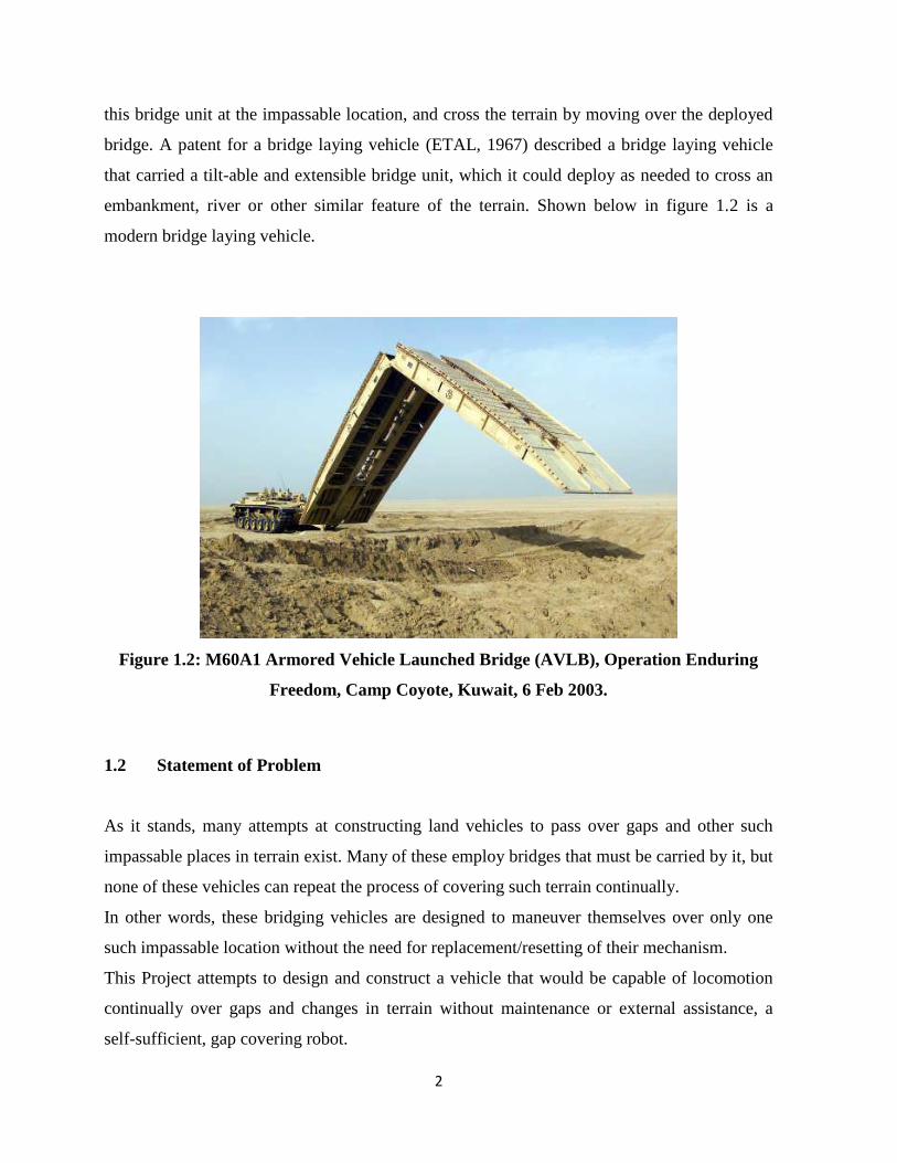
this bridge unit at the impassable location, and cross the terrain by moving over the deployed
bridge. A patent for a bridge laying vehicle (ETAL, 1967) described a bridge laying vehicle
that carried a tilt-able and extensible bridge unit, which it could deploy as needed to cross an
embankment, river or other similar feature of the terrain. Shown below in figure 1.2 is a
modern bridge laying vehicle.
Figure 1.2: M60A1 Armored Vehicle Launched Bridge (AVLB), Operation Enduring
Freedom, Camp Coyote, Kuwait, 6 Feb 2003.
1.2 Statement of Problem
As it stands, many attempts at constructing land vehicles to pass over gaps and other such
impassable places in terrain exist. Many of these employ bridges that must be carried by it, but
none of these vehicles can repeat the process of covering such terrain continually.
In other words, these bridging vehicles are designed to maneuver themselves over only one
such impassable location without the need for replacement/resetting of their mechanism.
This Project attempts to design and construct a vehicle that would be capable of locomotion
continually over gaps and changes in terrain without maintenance or external assistance, a
self-sufficient, gap covering robot.

3
1.3 Objectives
The Idea of this project is to construct a gap-covering vehicle, consisting of two identical four-
wheeled bases linked by a rigid beam with a sliding weight system. The objectives of this
project are as follows.
Firstly, This Project aims to design a functional weight shifting system in order
to actively change the center of gravity of the robot.
Secondly, the four wheeled base need to be constructed. It would need to be
capable of locomotion.
The sliding weight system and bases need to be integrated into one functional
robot.
The control system for the robot needs to be designed and constructed. For the
purposes of this project, manual control of the robot is sufficient.
Testing of the robots functionality should be done in a controlled environment.
1.4 Scope
This project will limit itself to the manual control of the robot over a fully automated
control loop as this project is to act as a proof of concept for such a system.
The wheeled motion using the base will be left as an option, as the main concern is to
create a functional weight shifting system to allow the pivoting of the robot on each
base to loco mote its linked counterpart.

4
Chapter 2
Literature Review
This Chapter will follow to summarize some of the work that has already been carried out in
this field, and also to expose some similar attempts at constructing this sort of device. All the
work displayed here has been fully credited to their respective authors.
2.1 Centre of gravity shifting Systems
Systems to alter the Centre of gravity of vehicles were initially designed and built for
submarines in order to control their pitch angles whilst submerged. There were many such
systems that were designed. One of the earlier designs is described in a patent defined as a
‘Centre of gravity shifting device for submarine boats’ (HARRY B. YOUNG, 1917), which is
shown below in figure 2.1.
Figure 2.1: Submarine Center of gravity shifting system

5
The system depicted above was designed to shift the weight of the submarine to its fore or aft,
by means of changing position of the weighted trolley at the base of the hull along its length.
This would cause the distribution of weight across the body of the submarine to change,
causing its overall center of gravity to shift towards the side that the trolley was shifted to. In
this manner the tilt angle of the submarine could be controlled and changed as needed.
Another System that was designed to shift the center of gravity of its host vehicle is shown
below in figure 2.2, and is described in a patent ‘HYDRAULIC MERCURY TRANSFER
SYSTEM’ (Ray F. Hinton, 1967)
Figure 2.2: Mercury Center of gravity shifting system
This system harnessed a liquid mercury transfer system in order to change the position of the
Centre of gravity of the submarine as needed. A pump system would transfer liquid mercury

6
from one tank (fore) to the other tank (aft) as needed to alter the Centre of gravity, in order to
change the submarines’ pitch.
2.3 Microcontrollers
Microcontrollers are self-contained systems that consist of processors, peripherals and
memory that can be used as embedded systems for robots and other devices. Microcontrollers
vary from simple controllers to fully programmable units that can control sophisticated
systems.
Programmable microcontrollers contain general purpose input/output pins. The number of
these pins varies depending on the microcontroller. They can be configured to an input or an
output state by software. When configured to an input state, these pins can be used to read
external signals or sensors. When they are configured to the output state, they can drive
external devices like LED displays and motors.
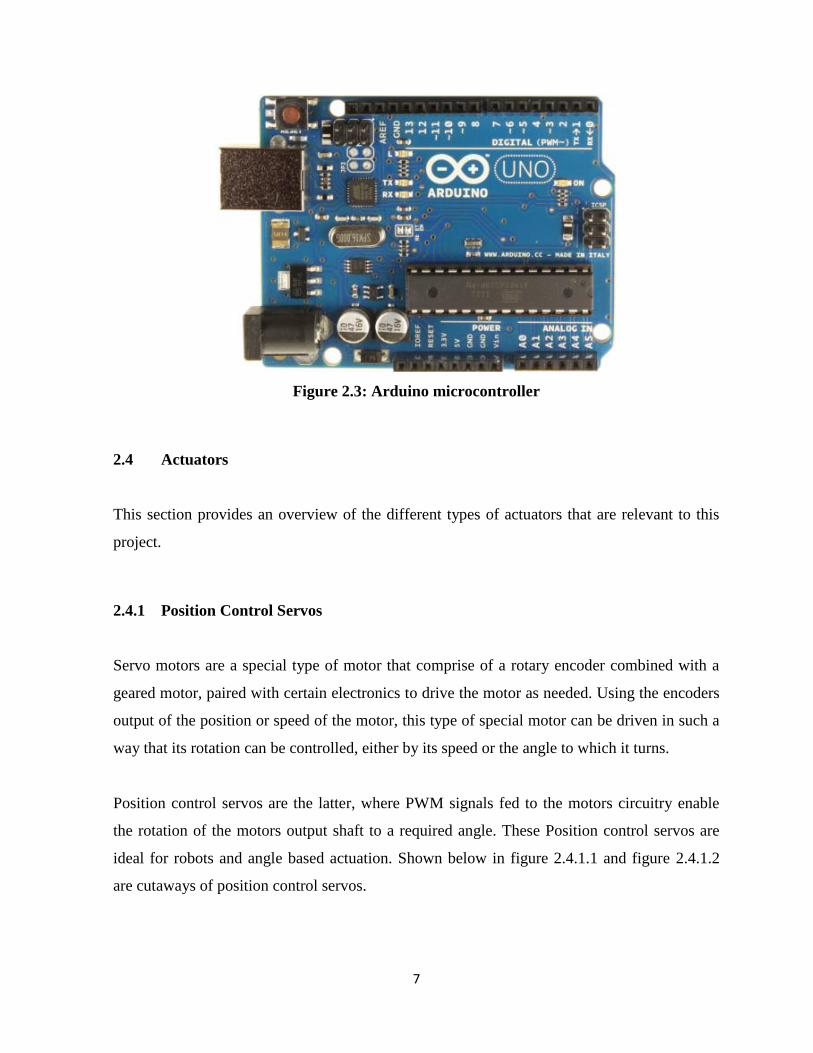
2.3.1 Arduino Microcontroller
Arduino microcontrollers are an open source microcontroller series that is mainly used as
electronic prototyping platforms for robots and other devices. These controllers range from
simple processors to ore advanced boards that can control a variety of hardware components
and utilize them in operation. Shown below in figure 2.3 is an Arduino UNO microcontroller
board, one of the simpler models used for small devices.
7
Figure 2.3: Arduino microcontroller
2.4 Actuators
This section provides an overview of the different types of actuators that are relevant to this
project.
2.4.1 Position Control Servos
Servo motors are a special type of motor that comprise of a rotary encoder combined with a
geared motor, paired with certain electronics to drive the motor as needed. Using the encoders
output of the position or speed of the motor, this type of special motor can be driven in such a
way that its rotation can be controlled, either by its speed or the angle to which it turns.
Position control servos are the latter, where PWM signals fed to the motors circuitry enable
the rotation of the motors output shaft to a required angle. These Position control servos are
ideal for robots and angle based actuation. Shown below in figure 2.4.1.1 and figure 2.4.1.2
are cutaways of position control servos.

8
Figure 2.4:Servo Figure 2.5:Servo cutaway
2.4.2 DC Hobby motors
DC hobby motors are cheap, simple DC motors that are normally incorporated into both
geared motors as well as directly into gearboxes and drivetrains for robots and remote
controlled vehicles. These motors operate using permanent magnet stators and coil rotors.
Shown below in figure 2.6 (Left) is a depiction of a geared DC motor as well as a simple
hobby motor without augmentation (right). Figure 2.7 below shows a DC hobby motor
incorporated into a gearbox drive unit (Tamiya).
Figure 2.6: DC motors

9
Figure 2.7: Tamiya gearbox

10
Chapter 3
Methodology
This Chapter explains the methodology that was followed to reach the successful completion
of this project. The Project underwent multiple reworks and changes before it reached
completion, of which the work carried out could be broken into three separate rover models.
The original Design (Mark I) that was proposed utilized a different structure and control
system from the second, more advanced and functionally superior rover (Mark II). The second
rover model was designed to be constructed in lightweight acrylic, but due to certain
requirements this model had to be reworked to be constructed in aluminum. This led to the
production of the third and final model (Mark III). This section will elucidate the work that
was done on each model.
The Work carried out can be categorized into the following parts.
Framework
Mechanical Construction
Control system construction
Programming and control logic
Each Aspect of the work carried out will be explained in detail in this section.

11
3.1 Framework
This section refers to the overall system that needs to be designed, consisting of the
mechanical, control and logic components required for the construction of the robot. The
original system design that was to be implemented is displayed below in figure 3.1. This
system was originally designed for implementation on the Mark I rover model, thus the
requirement and use of position controll servos is noted. It was decided that the rover be
controlled by a microcontroller unit, which would oversee the sensing and actuation systems
onboard.
Figure 3.1: Framework – Mark I
Following the decision to change the design of the rover, the overall system had to be
overhauled as well due to drastic changes in the mechanical design and the different actuators
used. The newly designed system was intended for use with the Mark II rover design, but was
kept unchanged even with the shift over to the Mark III. The main change in this system was
12
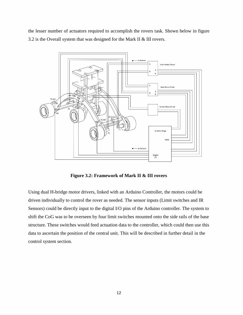
the lesser number of actuators required to accomplish the rovers task. Shown below in figure
3.2 is the Overall system that was designed for the Mark II & III rovers.
Figure 3.2: Framework of Mark II & III rovers
Using dual H-bridge motor drivers, linked with an Arduino Controller, the motors could be
driven individually to control the rover as needed. The sensor inputs (Limit switches and IR
Sensors) could be directly input to the digital I/O pins of the Arduino controller. The system to
shift the CoG was to be overseen by four limit switches mounted onto the side rails of the base
structure. These switches would feed actuation data to the controller, which could then use this
data to ascertain the position of the central unit. This will be described in further detail in the
control system section.
13
3.2 Mechanical Construction
This section is dedicated to the work that was carried out in designing and constructing the
physical body of the gap covering robot. This section will be separated into two parts,
Design
Construction
3.2.1 Design
This Section will describe the design work that was carried out in order to fabricate the
mechanical aspect of the robot.
Mark I Rover
This was the design submitted in the original proposal for this project. A simple, practical and
functional design for a rover which could shift its center of gravity back and forth in order to
overcome difficult terrain. This design could be broken down into three separate components.
The mechanical component consists of the following.
Wheeled/ Tracked base units
Sliding weight Unit
Linking Beams and angle control servo unit
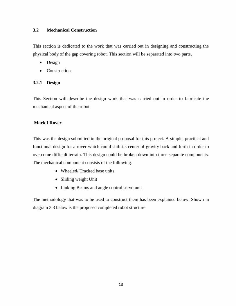
The methodology that was to be used to construct them has been explained below. Shown in
diagram 3.3 below is the proposed completed robot structure.

14
Figure 3.3: Mark I – Side view
The manner in which the Mark I rover was to function is as follows. As shown in figure 3.4
below, the center of gravity (CG) shifting system could shift between the extreme ends of the
linking beams, changing the position of the overall CG of the vehicle. This change could be
achieved such that the CG could be shifted directly above either one of the base units. This
meant that the rover could balance itself entirely on one base unit.
The use of caterpillar tracks on the bases allows the Mark I to loco mote terrain even while
balanced entirely on one base, meaning that the vehicle could veer out over an edge as shown
in the diagram. Once the far end of the rover was safely over the gap, the CG shifting unit
could then be moved cross over to the other end, so that the rovers balance be shifted onto the
opposing end. The same process could then be repeated and the vehicle could successfully
travel over the gap.

15
Figure 3.4: Function – Mark I
Each section of the Mark I rover is explained in the following sections.

16
Wheeled/ Tracked Base unit(s)
The base unit was to be constructed as described following. Two geared DC motors will be
mounted onto a square acrylic sheet, as shown in figure 3.5. Two wheels will be mounted onto
the motors, and two free-spinning wheels will be mounted parallel to the axis of the motors as
shown. The wheels spinning on the same side will then be connected to each other via
caterpillar tracks. Finally, a mount for the position control servo of the linked beams will be
fitted on the empty side of the acrylic sheet. Refer figure 3.5. for the proposed base unit
design.
Figure 3.5: Mark I – Base unit

17
Sliding Weight unit
This unit is to act as a moveable weight unit, in order to allow the center of gravity of the
Robot to be shifted directly over each base, individually. This would allow the robot to
balance itself on each of the bases as needed. It would consist of all the electronic components
(such as the microcontroller and the battery pack) and the motor to allow translation of the unit
along the linking beams. Refer figure 3.6 for the proposed sliding weight unit design.
Figure 3.6: Mark I- CG shifting system
Linking Beams and angular control servo unit
This unit refers to the two parallel beams that link the two base units rigidly together. This
section also allows the sliding weight to move along the beams to shift the robots weight.

18
Mark II rover
The Mark II rover was the successor to the Mark I rover, and was designed for multiple
purposes. The Mark II was constructed keeping the rovers weight in mind, as well as the
structural strength required in the linking beams of the Mark I model. This rover answered
many of the practical limitations posed by the Mark I. Shown below in figure 3.7 is a draft of
the Mark II.
Figure 3.7: Mark II - schematic
The Mark II was designed as a simpler, but more efficient gap covering rover. Though this
design sacrifices some of the robustness of its predecessor, this rover requires a lesser number
of actuators, has a higher length to maximum coverable gap ratio, and has a lighter
construction. This rover utilizes a curved linking beam section, which serves as a stronger
structure to allow the central shifting unit to slide across from one end to the other.

19
This curved beam section acts as the base of the vehicle, and has mounted on it four motors,
each supplying power individually to one of the four main wheels. This allows for
independent wheel control, allowing a wide range of motion control.
By combining a shifting set of wheels onto the center of gravity (CG) shifting system, this
design, along with its curved linking beam structure, allows the vehicle to lift up its fore or aft
ends by pivoting itself on these central wheels. This set of central wheels also allows
locomotion of the rover in its extreme shifted states, be it forward shifted or aft shifted. The
central wheels were mounted such that the polygon formed by the four wheels in contact with
the ground when the vehicle balances on one end forms a near perfect square, in order to allow
efficient turning of the rover. This means that the rover could achieve rotational movement to
change its heading whilst stationery. Another purpose served by the mobile wheels mounted
on the central unit was to allow the height to which the raised end of the vehicle to be
adjusted. Figure 3.8 is a diagram depicting this range of motion.
Figure 3.8: Mark II & III – Functions
20
The Mark II rovers design can be broken into two sections. Unlike the three sectioned Mark I,
only two separate units are present in this rover.
Base Unit
CG Shifting unit
Meant to be constructed in acrylic, the vehicle weighed in at slightly over 490grams in its
barebones. The Mark II was designed and drafted on NX 8.0 for construction. The following
pages will provide a detailed overview of the vehicle design.
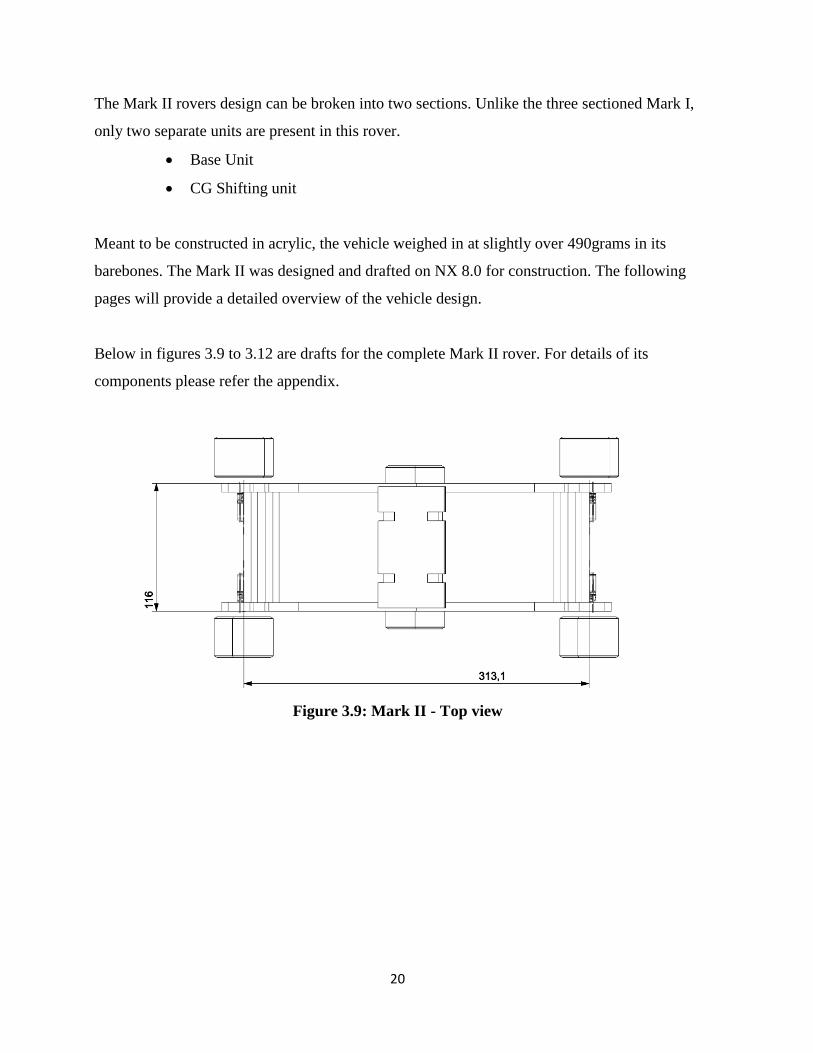
Below in figures 3.9 to 3.12 are drafts for the complete Mark II rover. For details of its
components please refer the appendix.
Figure 3.9: Mark II - Top view

21
Figure 3.10: Mark II - Right View
Figure 3.11: Mark II - Front view

22
Figure 3.12: Mark II - Trimetric view
Shown in Figure 3.13 below is a rendering of the Separate CG shift unit along with its motor.
Figure 3.13: Mark II - CG shifting unit
23
The battery pack which would serve to provide power to the microcontroller unit and the
actuators was intended to be mounted at the topmost portion of the CG shift unit, to act as a
counter weight when the CG shift unit was at the far ends.
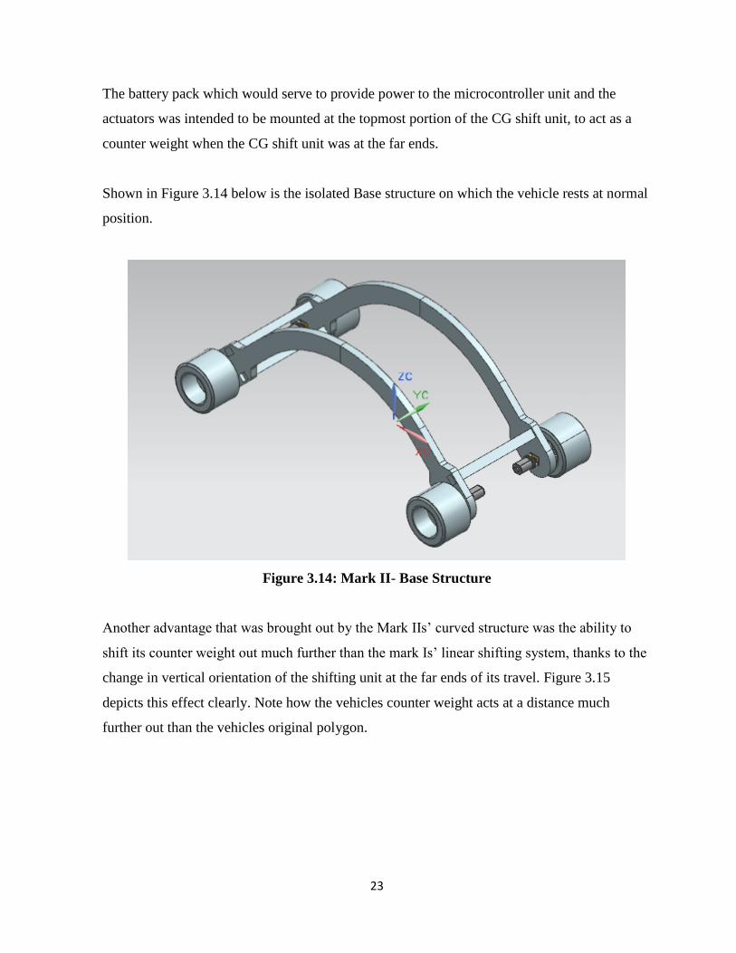
Shown in Figure 3.14 below is the isolated Base structure on which the vehicle rests at normal
position.
Figure 3.14: Mark II- Base Structure
Another advantage that was brought out by the Mark IIs’ curved structure was the ability to
shift its counter weight out much further than the mark Is’ linear shifting system, thanks to the
change in vertical orientation of the shifting unit at the far ends of its travel. Figure 3.15
depicts this effect clearly. Note how the vehicles counter weight acts at a distance much
further out than the vehicles original polygon.

24
Figure 3.15: Moment about pivot
The specifications of the Mark II are as follows; all weights were calculated to within an
accuracy of 5g.
Length of Robot ~ 315mm ± 0.5mm (across wheel axes)
Width of Robot ~ 115mm ± 0.5mm (across side plates)
Height of robot ~ 150mm ± 0.5mm (variable)
Weight:
Base unit 230g ± 5g
Travelling structure 250g ± 5g
Centre motor 50g ± 5g
Wheel motor 23g ± 5g
Wheel 15g ± 5g
Arduino Mega 40g ± 5g
Battery Pack 127g ± 5g
25
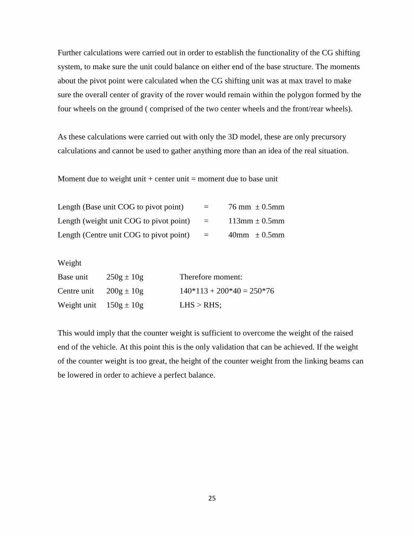
Further calculations were carried out in order to establish the functionality of the CG shifting
system, to make sure the unit could balance on either end of the base structure. The moments
about the pivot point were calculated when the CG shifting unit was at max travel to make
sure the overall center of gravity of the rover would remain within the polygon formed by the
four wheels on the ground ( comprised of the two center wheels and the front/rear wheels).
As these calculations were carried out with only the 3D model, these are only precursory
calculations and cannot be used to gather anything more than an idea of the real situation.
Moment due to weight unit + center unit = moment due to base unit
Length (Base unit COG to pivot point) = 76 mm ± 0.5mm
Length (weight unit COG to pivot point) = 113mm ± 0.5mm
Length (Centre unit COG to pivot point) = 40mm ± 0.5mm
Weight
Base unit 250g ± 10g Therefore moment:
Centre unit 200g ± 10g 140*113 + 200*40 = 250*76
Weight unit 150g ± 10g LHS > RHS;
This would imply that the counter weight is sufficient to overcome the weight of the raised
end of the vehicle. At this point this is the only validation that can be achieved. If the weight
of the counter weight is too great, the height of the counter weight from the linking beams can
be lowered in order to achieve a perfect balance.
26
Mark III Rover
The Mark II’s design was successful in simulations on NX 8.0, and the design was put for
construction. Unfortunately, requirements were laid out for the body of the rover to be in
metal.
This meant that the 8mm thick sheets used in this model would be too heavy if cast in metal,
as it was originally intended for lightweight acrylic. This brought about the necessity to
change the Mark II’s design to accommodate a heavier construction material, while keeping
its overall structural weight in check. The Mark III was the outcome of the changes that were
made.
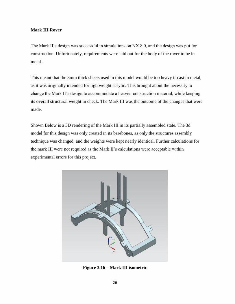
Shown Below is a 3D rendering of the Mark III in its partially assembled state. The 3d
model for this design was only created in its barebones, as only the structures assembly
technique was changed, and the weights were kept nearly identical. Further calculations for
the mark III were not required as the Mark II’s calculations were acceptable within
experimental errors for this project.
Figure 3.16 – Mark III isometric

27
As it can be deduced from the rendering, the Mark III was designed to allow its construction in
aluminum sheeting, of 3mm in thickness. This used a much thinner sheet compared to the
Mark II (which used 8mm sheet) thus allowing the use of heavier construction material.
The Mark III employs a folded sheet assembled structure, featuring multiple bends and curves
to strengthen its fairly thin construction. Designed for assembly using a simple nut and bolt
system, the ability to disassemble and make changes was kept open.
The main changes that were made to the Mark II to the Mark III is the noticeable usage of
additional guide rails mounted perpendicular to the curved structure. This was done due to the
reduction in sheet thickness, as a 3mm sheet would be incapable of supporting guide wheels
for the CG shifting system to slide atop. The other change was the removal of multiple cross
beams which were then replaced with L-bars for added strength, and a lesser weight.
The central CG shifting systems hollow lower section was also replaced with a tapered solid
beam, which used less material than the double pronged design on the Mark II. The central
units’ assembly technique was changed from the slot and through beam, to L-bars bolted to
either plate. This technique served the double purpose of providing a thicker support frame for
the guide wheels of the CG shifting unit.
The rail used to provide movement to the CG shifting system was removed due to the
difficulty of manufacturing a curved rail in aluminum with the current skills in machining that
was processed. It was then replaced with a more practical approach to the problem, the use of
a timing belt. This timing belt would be cut to form a linear rail, and attached to the flat
surface provided by the guide rail on the base structure. Details of this can be found in the
Construction section.
Shown below in the figures below are a few renderings of the Mark III model. Its complete
drafted design can be found attached in the appendix.

28
Figure 3.17: Top View Mark III
Figure 3.18: Right View Mark III

29
Figure 3.19: Front View- Mark III
This Design was the final one selected for construction. It fabrication is described in detail in
the following section. Many changes were made following this due to changes in
requirements, though these changes were minor.
3.2.2 Construction
This Section describes the work that was carried out in construction of the designed rover.
The work that was carried out can be broken down as follows.
Machining
This refers to all the cutting, milling and other rough work that was carried out to
manufacture the components of the rover.
Assembly
This refers to the assembly of the bare-bone structure from the components that were
manufactured.

30
Machining
The first task that was carried out was the machining of the sheet based components for the
rovers primary structure. A 300x600mm, 3mm aluminum sheet was used for this (refer
appendix for image). Once the drafts were marked onto the sheet for cutting, a Jigsaw was
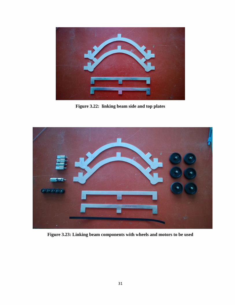
used to cut out the components rough shapes. Figures 3.20 to 3.22 show how these sheets
were marked for cutting, and the different stages of cutting. Figure 3.23 and 3.24 show
some of the main components of the base structure and the shifting units’ components after
they were cut out.
Figure 3.20: sheet marked for cutting
Figure 3.21: Partially cut Linking Beam side plate
31
Figure 3.22: linking beam side and top plates
Figure 3.23: Linking beam components with wheels and motors to be used

32
Figure 3.24: CG shift unit side plates (right)
Once the parts were all cut out of the sheet, folding, bending and drilling procedures were
carried out. Basic metal working techniques had to be studied to successfully carry out these
tasks without sacrificing the structural strength of the body. Figure 3.25 shows one of the side
plates being drilled to lighten its structure.
Figure 3.25: drilling side plate

33
Once the sheet metal components were completed, certain support structures and mounting
units that needed to be stronger than that offered by the sheet metal had to be manufactured.
This work was done on a three-axis milling machine and lathe machine. The use of these
machines had to be learnt from scratch, and a great deal of time was spent learning and
mastering them. Once competent enough, the mounting units were milled out as shown in
figures 3.26 to 3.27.
Figure 3.26: axle Mounts and central wheel mounts
Figure 3.27: horizontal guide rail and mount
These pieces were milled from 10mm x 20mm x 100mm blocks of solid aluminum, which
were first planed on all sides using the milling machines end mill. Once the blocks were
34
uniformly planed, they were the removed of excess material until the desired block size was
achieved. The more complex guide rail mount was shaped manually as desired using the three
axis milling machines end mill, and its’ combined feed operations. Refer the appendix for
more images of machining being carried out.
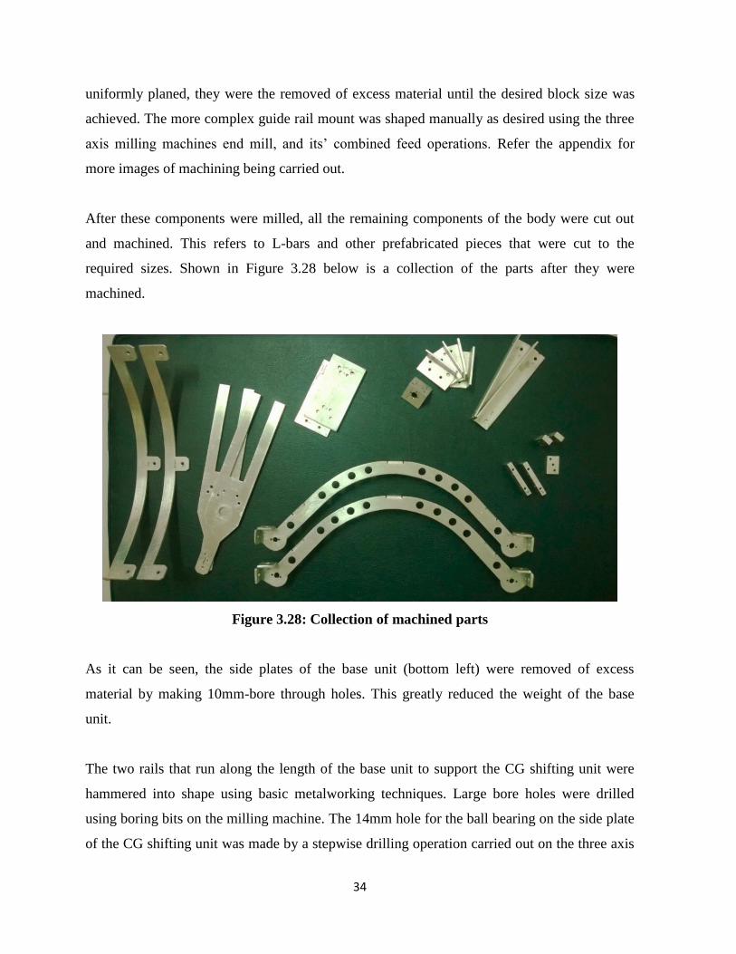
After these components were milled, all the remaining components of the body were cut out
and machined. This refers to L-bars and other prefabricated pieces that were cut to the
required sizes. Shown in Figure 3.28 below is a collection of the parts after they were
machined.
Figure 3.28: Collection of machined parts
As it can be seen, the side plates of the base unit (bottom left) were removed of excess
material by making 10mm-bore through holes. This greatly reduced the weight of the base
unit.
The two rails that run along the length of the base unit to support the CG shifting unit were
hammered into shape using basic metalworking techniques. Large bore holes were drilled
using boring bits on the milling machine. The 14mm hole for the ball bearing on the side plate
of the CG shifting unit was made by a stepwise drilling operation carried out on the three axis

35
milling machine, starting with a minute 3mm drill bit, and working all the way up to the final
14mm end mill.
The corners of the Components were filleted by the use of steel files (rasps) of multiple
grades, and the use of a flap disc mounted on an angle grinder. Once this was done, the parts
were polished using an orbit finishing sander to removes scratches and blemishes on the
surfaces that were the side effect of machining. This gave the structure a clean finish. Figure
3.29 shows one of the finished center wheel mounts attached to the central side plate.
Figure 3.29: finished wheel mount with wheel attached
Once finishing work was carried out on the machined components, the Machining phase of the
construction was complete. This left the next stage, assembling the machined components.

36
Assembly
Before assembly of the machined components was to be carried out, a few more components
were assembled that were needed using pre-fabricated components. This included the
following components;
Guide wheels for CoG shifting system
Primary Wheel assembly
The guide wheels for the CoG shifting system were constructed as follows. A 3mmx 30 mm
stainless steel axle was used as the core of the guide wheel, onto which two ball bearings with
an outer diameter of 6mm were fitted. These ball bearings were then locked in place by the use
of 3mm circlets. Once this was done, a 20 mm diameter rubber wheel with a hollow inner core
of 6mm was slid onto the bearings, forming a makeshift low friction wheel with a high
robustness.
Figure 3.30 to 3.35 show the construction of these guide wheels step by step.
Figure 3.30: rubber wheel Figure 3.31: Ball bearing Figure 3.32:
circlet
Figure 3.33: 3mm axle with circlets
37
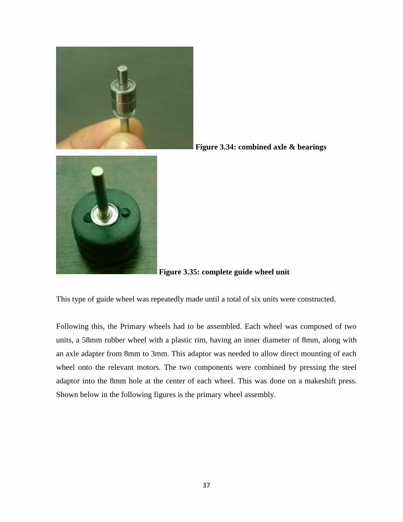
Figure 3.34: combined axle & bearings
Figure 3.35: complete guide wheel unit
This type of guide wheel was repeatedly made until a total of six units were constructed.
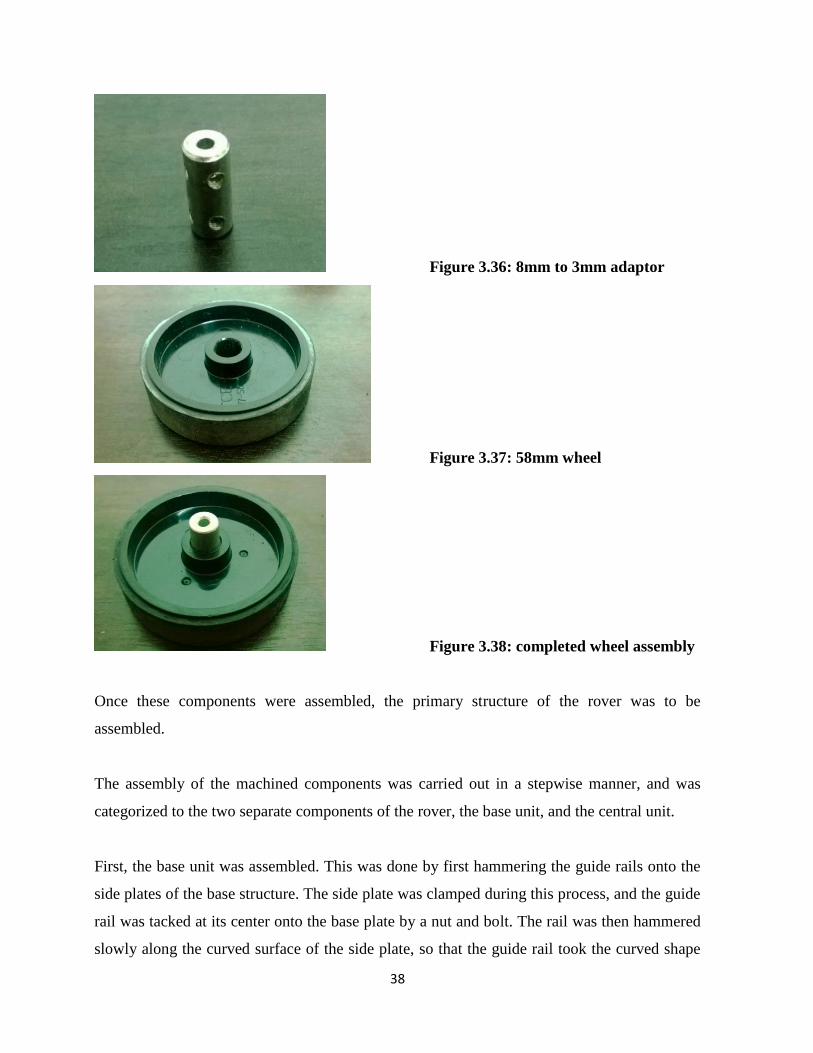
Following this, the Primary wheels had to be assembled. Each wheel was composed of two
units, a 58mm rubber wheel with a plastic rim, having an inner diameter of 8mm, along with
an axle adapter from 8mm to 3mm. This adaptor was needed to allow direct mounting of each
wheel onto the relevant motors. The two components were combined by pressing the steel
adaptor into the 8mm hole at the center of each wheel. This was done on a makeshift press.
Shown below in the following figures is the primary wheel assembly.
38
Figure 3.36: 8mm to 3mm adaptor
Figure 3.37: 58mm wheel
Figure 3.38: completed wheel assembly
Once these components were assembled, the primary structure of the rover was to be
assembled.
The assembly of the machined components was carried out in a stepwise manner, and was
categorized to the two separate components of the rover, the base unit, and the central unit.
First, the base unit was assembled. This was done by first hammering the guide rails onto the
side plates of the base structure. The side plate was clamped during this process, and the guide
rail was tacked at its center onto the base plate by a nut and bolt. The rail was then hammered
slowly along the curved surface of the side plate, so that the guide rail took the curved shape

39
without deforming .once the rail was hammered to one of the edges, the screw on that corner
would be placed in and tightened lightly to prevent the recoil of the rail. This was done to
either side, leaving the rail smoothly fitted onto the side plated. The combined structure was
then removed from the clamp, and the screws were tightened as needed.
The combined side plates then had to be fitted together to form the complete base structure.
This was done by bolting two L-bars cut to a length of 136mm onto the folded flaps of the side
plates. Holes were bored into the flaps and the L-Bars by the use of a C-clamp and drill press.
4mm screws were used for this instead of the 3m ones used on the central unit due to the
increased strength requirements. Figure 3.40 below shows the combined base structure in its
bare bones.
Once the Base unit was assembled, the bare bone central unit was assembled. This first
required the two side plates of the central unit to be fitted together by the rectangular plate
mounted horizontally in-between them. The short 50mm L-bars that were cut out were bolted
to each side plate by two screws, as shown in Figure 3.39. The free ends of the L-bars were
then screwed onto the flat rectangular plate as shown in the same figure. The ball bearing for
the motors gearhead (to act as the pinion on the rack and pinion mechanism) was placed into
the 14mm hole on the right side plate using hot glue to fasten it. This formed the basic central
unit, with the exclusion of the motor mount.
Figure 3.39: Central unit in bare bone assembly

40
Figure 3.40: Bare bone structure of base unit with central unit atop it
Once the bare bone structures were assembled, the rack and pinion mechanism used to shift
the CoG of the rover was tested. This was done by mock assembly of the shifting system. The
guide wheels that were assembled prior to this were mounted on a flat plate, along with the
pinion.
The timing belt was attached to one of the rails, and placed into the space between the guide
wheels and the pinion, shown in figure 3.41. This rail was moved back and forth, to make sure
that appropriate frictional forces would be present; enough to keep the rail sturdy, but not too
great a force to hinder its motion.

41
Figure 3.41: testing CG shifting mechanism
Once it was established that the center of gravity shifting system designed for the rover was
functional, further assembly was carried out until everything was fitted together, to leave only
the mounting of sensors and control architecture.
First, the central unit was completed. Step one was fitting the central motor mount beneath the
rectangular cross plate. This was followed by the fitting of guide wheel mount blocks, and the
primary wheel mounting blocks. These blocks were fitted onto the central unit by means of
15mm long screws(3mm diameter) tightened by nuts. The second cross plate was then
mounted at its proper position, leaving a slot in the center of the structure for the battery
packs, and providing more lateral strength to the structure.
Once the structural components were fitted, the central motor was mounted onto its mounting
plate using four 1.5mm screws. The pinion for the CG shifting system was then mounted onto
the motor axle and fastened with its locking bolt. Once the motor was fastened in place, the
two primary wheels to be mounted at the bottom of the central unit were fitted through 3mm
axles, and locked in place by circlets. This marked the completed assembly of the central unit,
leaving only mounting work to be done. The Figure 3.42 shows the central unit at this point.

42
Figure 3.42: fully assembled central unit
Following the completion of the central unit, the Base structures completion was next.
The L-bars connecting the two side plates of the base structure were slotted on the three axis
milling machine to lighten them, which was done using basic slotting techniques with a 10mm
end mill and controlled x/y axis feeding. The figure below shows the lightened structure.
Figure 3.43: Slotted connecting L-bar
43
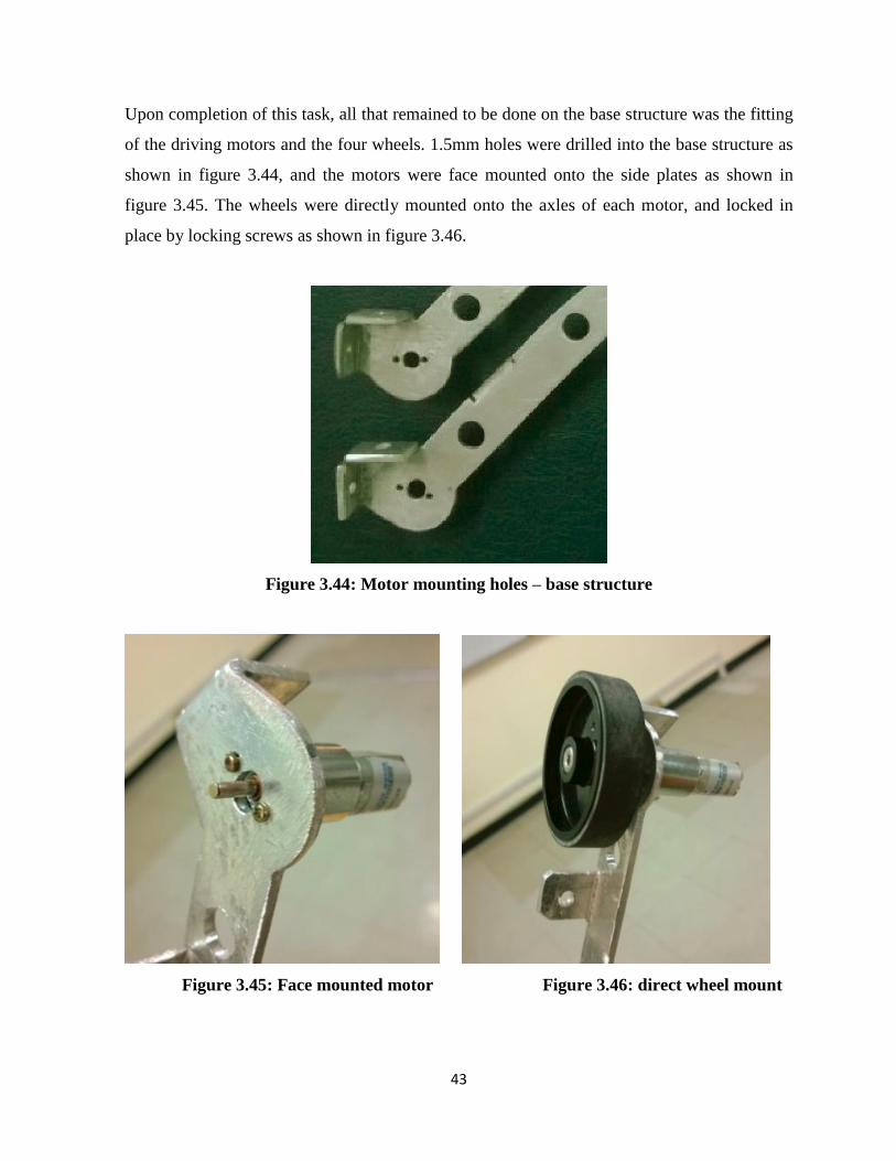
Upon completion of this task, all that remained to be done on the base structure was the fitting
of the driving motors and the four wheels. 1.5mm holes were drilled into the base structure as
shown in figure 3.44, and the motors were face mounted onto the side plates as shown in
figure 3.45. The wheels were directly mounted onto the axles of each motor, and locked in
place by locking screws as shown in figure 3.46.
Figure 3.44: Motor mounting holes – base structure
Figure 3.45: Face mounted motor Figure 3.46: direct wheel mount
44
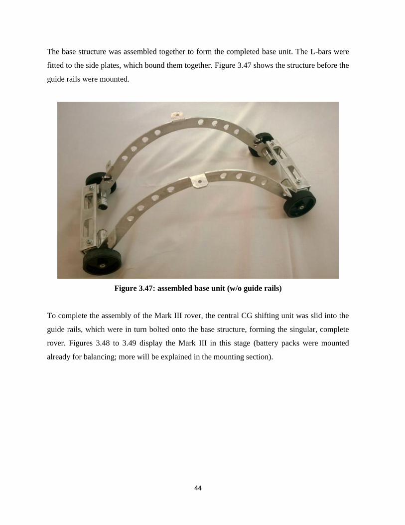
The base structure was assembled together to form the completed base unit. The L-bars were
fitted to the side plates, which bound them together. Figure 3.47 shows the structure before the
guide rails were mounted.
Figure 3.47: assembled base unit (w/o guide rails)
To complete the assembly of the Mark III rover, the central CG shifting unit was slid into the
guide rails, which were in turn bolted onto the base structure, forming the singular, complete
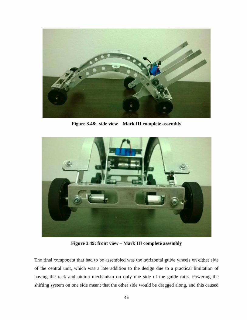
rover. Figures 3.48 to 3.49 display the Mark III in this stage (battery packs were mounted
already for balancing; more will be explained in the mounting section).
45
Figure 3.48: side view – Mark III complete assembly
Figure 3.49: front view – Mark III complete assembly
The final component that had to be assembled was the horizontal guide wheels on either side
of the central unit, which was a late addition to the design due to a practical limitation of
having the rack and pinion mechanism on only one side of the guide rails. Powering the
shifting system on one side meant that the other side would be dragged along, and this caused

46
a slight tilting of the central unit in motion, which in turn caused friction and wear. As a
solution, limiting guide wheels were placed to prevent this lateral yawing motion. These guide
wheels were mounted as shown in the figure below. By using a pair of ball castors, the lateral
motion was limited.
Figure 3.50: lateral guide wheels
This marked the end of the construction phase, leaving only the mounting of sensors and
control circuitry. The following section will cover the said topics.
‘

47
3.3 Control System
The control system for the Mark I was to be a microcontroller interfaced with the feedback
sensors and actuators to oversee the angular servo control, as well as the control of the four
base motors and the sliding weight control motor. The microcontroller would be interfaced
with the PC for manual control as well as programming.
The Mark II and Mark III models followed the same philosophy and were designed to be
controlled by an Arduino controller. The only difference in the architectures is the absence of
position control servos in the latter.
The microcontroller that was selected for use in the Mark III rover was the Arduino Mega
2560R3. This was due to the familiarity of using Arduino microcontrollers in the past, along
with the boards’ abundant PWM output ports, which the Mega has twelve of. Seeing that this
project required the use of 10 of these outputs, this board was quite convenient. Another
deciding factor was the abundance of digital I/O pins, which would be needed in large
quantities to account for the sensor and switch inputs. Figure 3.51 shows an Arduino mega
2560R3.
Figure 3.51: Arduino mega 2560 R3

48
The board could be fed 12v directly, which the board could cut down using its’ built in voltage
regulator, which was a nice feature as well. This allowed the use of larger 7.64V batteries in
the Rover. The following pages will describe the components that were selected in order to
suit the framework explained in section 3.1.
Limit Switches
These were three pole switches, consisting of a common, normally open, and normally closed
pin. For this project the Arduino was programmed to have its internal pull-up resistors active,
therefore the NO pins of the switches were connected to the digital pins on the Arduino, and
the common pins were grounded. Figure 3.52 shows one of the limit switches that were used.
Figure 3.52: Limit switch
IR Sensor
This sensor was also a three pole sensor, being calibrated to have a cutoff distance of 50mm.
Figure 3.58 shows the sensor that was used, the sharp GP2Y0D805Z0F sensor. The ground
pin was connected to the ground bus on the strip board, and the Voltage in was connected to
the bus line linked with the Arduinos’ 5V output pin. The output from the sensor was fed to
one of the digital pins of the Arduino.
49
Figure 3.58: Sharp GP2Y0D805Z0F
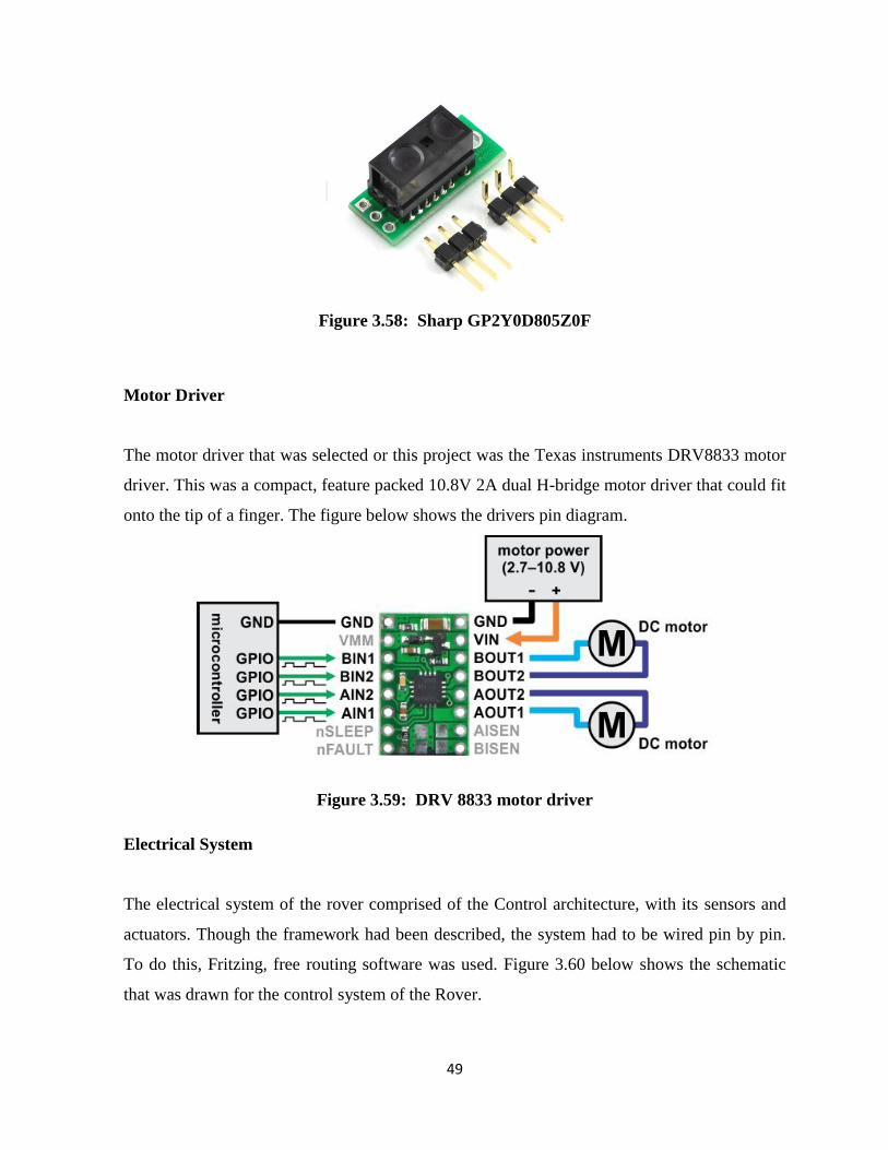
Motor Driver
The motor driver that was selected or this project was the Texas instruments DRV8833 motor
driver. This was a compact, feature packed 10.8V 2A dual H-bridge motor driver that could fit
onto the tip of a finger. The figure below shows the drivers pin diagram.
Figure 3.59: DRV 8833 motor driver
Electrical System
The electrical system of the rover comprised of the Control architecture, with its sensors and
actuators. Though the framework had been described, the system had to be wired pin by pin.
To do this, Fritzing, free routing software was used. Figure 3.60 below shows the schematic
that was drawn for the control system of the Rover.

50
The System was designed with the inclusion of a start and stop button, as well as a mode
toggle switch for the rovers control system. The importance of a stop button cannot be
expressed enough, as this would be the only way to prevent structural damage during testing
and debugging of the rovers control program.
The Rover was designed to house to two separate power supplies, one for the control system,
and one for the actuators. This was done to prevent damage that could be caused by
interference from the high current draw of the motors.
The electrical system was designed keeping in mind that the stop button would need to be used
in case of emergencies; hence it was routed to one of the Arduinos’ interrupt capable pins, in
order for it to act as a command override to halt all action.
Another bonus feature of the electrical system that was designed was the usage of a mode
switch, which could be programmed to toggle the system between a demonstration mode and a
manual control mode.

51
Figure 3.60: Electrical System Schematic
Mounting
Once the assembly of the mechanical system was complete, the mounting of control hardware
was necessary. As explained earlier, the Mark III required four limit switches to be mounted
along the length of the guide rails, as well as an IR sensor in the fore end of the rover.
The motor Drivers (DRV 8833) needed to be mounted, along with the Arduino mega
microcontroller. The manner in which these components were mounted will be discussed in
this section.

52
First, the Limit switches that oversees the position of the central unit along the guide rails
were mounted, by the use of hot glue. Simply gluing to the flat surface would not suffice;
therefore 1mm deep sinks were bore into the areas where the limit switches were to be
mounted, so that the glue would bind the switches firmly to the aluminum plate. Figure 3.61
below depicts one of the attached limit switches.
Figure 3.61: Limit switch mounting
To detect the center position (neutral) of the shifting unit, the two limit switches were mounted
in the same manner, as in figure 3.62.
Figure 3.62: center limit switch mounting

53
The IR sensor, a sharp GP2Y0D805Z0F was mounted in the same manner at the front edn of
the vehicle as shown in figure 3.63.
Figure 3.63: IR sensor mount
The battery packs were then mounted, as shown in figure 3.54 below. This was done by
sliding the Battery packs in the slot formed by the two cross plates of the central unit, and
locking them in place using vertical spacers.
Figure 3.64: Battery pack mounting

54
The Arduino Mega was then mounted, by using plastic PCB mounting clips. 3mm holes were
drilled into one of the side plates of the central unit, to fit the mounting holes on the Arduino
mega 2560R3. Once this was done, the clips were screwed onto the side of the central unit,
through these holes. The Arduino was then snapped into place, as shown in the figure below.
Figure 3.65: Arduino mount
Once the Arduino was mounted in place, the next step was to mount the motor drivers. The
DRV8833 motor driver was a 10.8 V 2A motor driver with many features. Figure 3.66 shows
one of these motor drivers. As there was a requirement for a start and stop button, as well as a
set of bus lines for the motor power and sensor power lines, a strip board was used to create a
mounting board. The three motor drivers were mounted on this board, along with the required
buttons. As an addition, a toggle switch was fitted as well, to act as a mode switch for the
rover. The Strip board that was constructed is shown in figure 3.67 in its mounted position
opposite the Arduino. The board was mounted in the same manner as the Arduino controller.

55
Figure 3.66: DRV 8833 Motor driver
Figure 3.67: Strip board containing motor drivers
Wiring
Once all the Circuit boards and sensors were mounted, the only remaining task was to wire
each of the components. This was one of the more tiresome tasks, and took much work.

56
As the entire central unit was mobile, the wiring for the base unit needed to be flexible and left
with enough free wire to accommodate the motion of the central unit to the extreme forward
position or the extreme backward position. This proved difficult as leaving too much wire
caused it to snag on other components and cause damage.
The wires also need to be kept out of the way of the moving parts, to prevent jamming and
structural damage. Many different techniques were used to finally end up with a functional
wiring method that could withstand the difficult working environment on the Rover.
As a safety precaution, all wires that were connected to the base unit from the central mobile
unit were fitted with detachable male/female connectors that would detach if excessive force
was applied. This would prevent structural damage to the base nit and/or the moving unit in
the event that one of the wires would get snagged. Figure 3.68 shows one such safety
connection.
Figure 3.68: Detachable Safety connection
All the connectors to the base units’ four motors were safetied this way, along with the IR
sensor and the Limit Switches.

57
The next safety feature that was implemented was the use of strategic routing through the
body of the rover. All the wires that went down from the central unit to the base structure were
routed through the Right side of the rover, completely avoiding the CG shifting systems
movement path (refer Figure 3.69). The wires were then fed into the base structure through the
holes in the side plates, avoiding contact with the primary wheels of the base unit (refer figure
3.70).
The next feature that was implemented to prevent damage was the clamping of wires into one
large ‘wire’. This was done to reduce the chances of wayward wires snagging on something,
and to reduce the possibility of wire breakage in handling. This also cleaned up the messy
outlook of the rover.
Figure 3.69: Wires to base unit routed from outside of rover to prevent snagging

58
Figure 3.70: Wires fed into base structure avoiding wheel
The Electrical wiring was carried out in the manner defined by the electrical schematic, with
the only exemptions being the use of bus lines mounted on the Strip board.
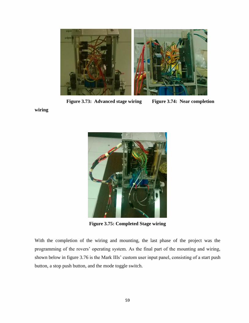
The following figures depict the rover in its wiring stages, up to completion.
Figure 3.71: Initial wiring stage Figure 3.72: Mid stage wiring
59
Figure 3.73: Advanced stage wiring Figure 3.74: Near completion
wiring
Figure 3.75: Completed Stage wiring
With the completion of the wiring and mounting, the last phase of the project was the
programming of the rovers’ operating system. As the final part of the mounting and wiring,
shown below in figure 3.76 is the Mark IIIs’ custom user input panel, consisting of a start push
button, a stop push button, and the mode toggle switch.

60
Figure 3.77: Stop/ Start buttons
3.4 Programming
The programming language used for this project was C++, written on Arduinos IDE.
The program that was written was intended for the purpose of serving as the operating system
of the Mark III rover.
The philosophy behind the program needed was simple. Instead of writing a direct control
sequence, functions were defined for each action that could be taken by the rover, with the
appropriate input variables.
Titled the ‘Inch Worm OS’ , the programs bare bones consisted of the Arduinos pins being set
up appropriately in accordance with the electrical schematic, and the functions that would be
needed by the rover in order to carry out all its tasks. These tasks could be broken down into
the following;
Forward movement
Backward movement
Checking the position of the central unit
Centering the shifting unit (neutral position)

61
Shifting the CG forward
Shifting the CG backward
Turning Right
Turning Left
Stopping immediately
The above tasks would each require the knowledge regarding the position of the central unit,
in order to optimize the algorithms that could be used by each function.
For Example, if the central unit was in neutral position, all four powered wheels of the base
would be in contact with the ground. This means that if the command to travel forward was
issued, the rover would need to run all four base motors to move forward.
On the other hand, if the rovers front end was in the raised position; i.e. Central unit was at the
rearward position, the front wheels of the base unit would only waste power if they were
switched on, because they would be in midair. The knowledge of the central units’ position
would allow the rover to decide which motors needed switching on and off on order to
efficiently control the rover.
The control functions would also each require and input parameter, such as the distance it
should travel, or the angle to which it should turn. As this projects scope does not include the
use of encoders, the implementation of such would allow a direct distance input by the user.
With the available input resources, the time duration through which the function should run
was used instead.
By defining a function to locate the central units’ position, each other function was optimized.
The four limit switches mounted along the guide rails allow the use of Boolean logic to locate
the central unit at six different positions; Forward, Backward, mid rear, mid front, mid, and
unknown.

62
The two mid mounted limit switches are mounted close to each other, such that both of the
switches will be actuated when the central unit is in the perfect centered position. This implies
that the direction of travel of the central unit across the middle can be identified by the use of
encoder logic. This also implies that the position of the central unit when none of the switches
are actuated is between the mid rear and rear switches or between the mid front and front
switches.
Using this knowledge it was possible to come up with an algorithm that identified and located
the position of the central unit along the guide rails. This function was defined as dollyPos() in
the OS that was written. The full code can be found in the appendix.
The remaining functions were written in the same manner, using Boolean logic to compare
and optimize their output. Once the functions were written, the Arduinos looping program had
to be written. The Systems logic flowchart is displayed in figure 3.78 below. The main
program can be found in the appendix.

63
Figure 3.78: Program Flowchart
The program was written with a dual-purpose loop, which used the mode switch that was
mounted on the strip board previously to switch between a straightforward demonstration
sequence and a manual control mode.

64
The automated sequence contained all the instructions the Mark III would need in order to
move towards, reach and traverse across a gap in the terrain, which would start when the
physical start pushbutton was pressed on the rover.
The manual input mode required serial communication between the rover and the PC, as the
keyboard was used as the means of control of the rover in this mode. A standard serial port
reading program was implemented in this mode, which would call different functions based on
the users serial input.
To streamline this mode, instead of using the Serial monitor provided in the Arduino IDE, a
key-logging program was run in Processing 2.0, a Java based open source program that has the
capability to link with Arduinos. This program was not used to link with the Arduino, but to
read the users key-presses and directly input them to the Serial port, without the need to press
the return key with each input. The coding used in the Processing 2.0 software can be found
attached in the appendix.
The program written in Processing 2.0 is similar to the serial port reading section of the main
program, the only difference being that instead of calling a function, the same input key value
is written to the serial port, so that the Arduinos program can identify it and act accordingly. In
other words, If the letter ‘w’ was pressed, the processing program will write the letter ‘w’ to
the serial port without the need for the enter button to be pressed, providing real-time control
system of the Rover.

65
Chapter 4
Testing and Results
This Section provides the results of the testing that was carried out using the Mark III gap
covering robot.
Tests were carried out to identify the following:
Gap covering Sequence Duration
Maximum payload (measured at topmost end of central unit)
Useful Battery Life
Accuracy of automated gap covering sequence
Ratio of vehicle length to maximum coverable gap length
Ratio of vehicle length to safely coverable gap length
Maximum height of raised end
Ratio of vehicle length to maximum coverable gap length
To identify the maximum gap that could be covered by the Rover, the ideal gap was
considered to be a hard surface, with a right angled edge. This meant that there would be no
tapering or rounding of the surface towards the edge. With this testing environment in mind,
the Mark IIIs’ gap covering capabilities were tested on the gap between two tables. By altering
this, the maximum distance that could be covered by the robot was measured, to an accuracy
of ±5mm, giving leeway to the flex of the structures rubberized components. This test was
carried out with manual control, and the maximum coverable gap that was measured was
found to be;
Table 0.1: Tabulation of Maximum Coverable Gap Length
Gap Length /mm 50 75 100 125 150 175 180 190 200 210
Outcome P P P P P P P P P F

66
Maximum coverable distance: 200±5mm;
Ratio of vehicle length to gap length = 200mm/ 315mm (wheel to wheel length)
= 63.3% of vehicles length can be covered.
*inaccuracy of 5mm addressed to the presence of flex in the joint between the central unit and
the base structure.
Ratio of vehicle length to safely coverable gap length
This test was carried out with the assumption that the gap being covered would not form a
perfect right angle to the surface. As an actual gap would possess a taper in the surface
towards it, the rover would not actually be able to move up to the absolute edge of the terrain;
i.e. Margin of safety would need to be left.
Here we make the assumption that the taper in the surface would be 10% of the gaps length.
This would mean that the rover would have to stop at a distance equal to 10% of the target
gaps length, without moving towards the extreme edge.
This would cause the distance that could be covered by the rover to be:
Max coverable gap: 200±5mm
Safety margin: 10%
Safety Distance: 20mm
Safely coverable gap length = (200-20) mm = 180 ±5mm
Ratio of vehicle length to gap length = 180mm/ 315mm (wheel to wheel length)
= 57.1% of vehicles length can be covered.
Gap covering Sequence Duration

67
The time taken for the Mark III gap covering robot to cover a gap of any length beneath its
max length would be the almost the same due to most of the time being consumed by the
change in position of the central unit. Therefore, for this test the most practical gap length was
used, the maximum safely coverable gap length.
The Duration of time taken for the robot to cover a gap of the safely coverable length of
180mm was measured for 6 repeated trials, which was the extent to which a fully charged
battery could be used effectively.
The test was carried out for the automated sequence in the robots program. The timer was
started when the rover stopped in front of the gap, and ended when the rear wheels of the rover
made contact with the opposing terrains surface.
Table 0.2: Tabulation of Sequence completion time
Trial No. 1 2 3 4 5 6
Start time 00:17 00:14 00:25 00:18 00:21 00:13
End time 01:08 01:04 01:15 01:10 01:12 01:03
Sequence
duration
51±0.5s 50±0.5s 50±0.5s 52±0.5s 51±0.5s 50±0.5s
Average sequence duration: (50+50+50 +52+51+50)/6 = 50.67s ±3s
Accuracy of automated gap covering sequence
The Accuracy of the automated gap covering sequence was measured by running the sequence
repeatedly over the same gap, and checking if the rover could successfully cover the gap.
Number of re-runs carried out: 10
Gap length: 180±5mm
Number of successful runs: 10
Success rate: 10/10
68
This test was sufficient to prove that the sequence functioned as necessary on a fully charged
battery. Unfortunately, continued testing is not possible consecutively due to limitations posed
by the batteries capacity. From these observations, the accuracy of the sequence can be
assumed to be 100%.
Although, taking into account real life problems that may arise, the accuracy of the gap
covering sequence should be taken as 95% from these observations, leaving out 5% in
accordance with the chaos theory.
Though these tests went without hassle, enough unexpected problems arose during initial
stages of testing that could never be predicted. Therefore it is only proper to leave space for
this type of error.
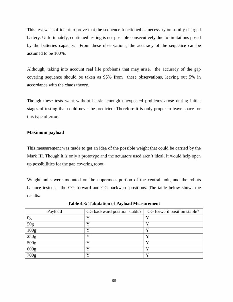
Maximum payload
This measurement was made to get an idea of the possible weight that could be carried by the
Mark III. Though it is only a prototype and the actuators used aren’t ideal, It would help open
up possibilities for the gap covering robot.
Weight units were mounted on the uppermost portion of the central unit, and the robots
balance tested at the CG forward and CG backward positions. The table below shows the
results.
Table 4.3: Tabulation of Payload Measurement
Payload CG backward position stable? CG forward position stable?
0g Y Y
50g Y Y
100g Y Y
250g Y Y
500g Y Y
600g Y Y
700g Y Y

69
The tests were stopped beyond the point of carrying 700g at the highest point of the CG
shifting unit, not because the robot became unstable, but due to the practical limitation posed
by the prototypes central motor.
The CG shifting systems motor could not support a weight higher than 700g and thus left the
shifting system inoperable. This is not a design limitation but a practical one. A newer
iteration of the Mark III could be equipped with a higher power actuator if a heavier weight
needed to be carried.
Thus, from these test results it can be ascertained that the maximum payload for the Mark III
is 700g, if mounted at the topmost portion of the central unit. Figure 4.1 shows the weight unit
mounted on the Mark III during testing.
Figure 4.1: payload test -600g
70
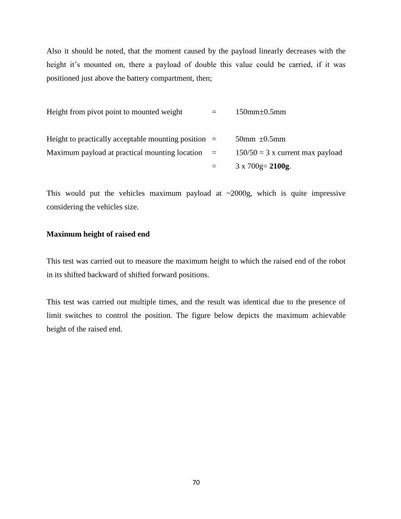
Also it should be noted, that the moment caused by the payload linearly decreases with the
height it’s mounted on, there a payload of double this value could be carried, if it was
positioned just above the battery compartment, then;
Height from pivot point to mounted weight = 150mm±0.5mm
Height to practically acceptable mounting position = 50mm ±0.5mm
Maximum payload at practical mounting location = 150/50 = 3 x current max payload
= 3 x 700g= 2100g.
This would put the vehicles maximum payload at ~2000g, which is quite impressive
considering the vehicles size.
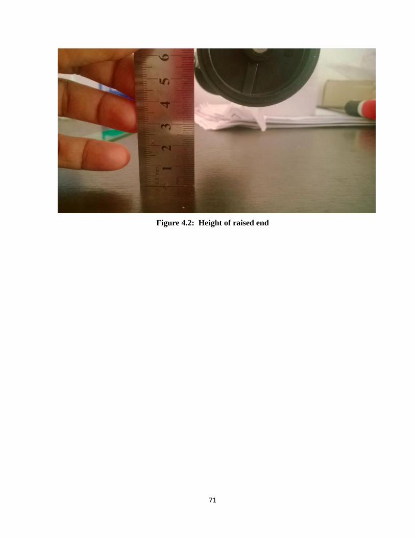
Maximum height of raised end
This test was carried out to measure the maximum height to which the raised end of the robot
in its shifted backward of shifted forward positions.
This test was carried out multiple times, and the result was identical due to the presence of
limit switches to control the position. The figure below depicts the maximum achievable
height of the raised end.
71
Figure 4.2: Height of raised end

72
Chapter 5
Conclusion
To conclude, the objectives that were stated in the original proposal were met, and far more
work was done afterwards, exceeding the outcome that was needed. The objectives were left
far behind and much progress was made than expected.
The Mark III gap covering robot performed exceedingly well, it accomplished its task of
overcoming a gap in terrain without difficulty, and proved to have extreme functionality by
being capable of proper locomotion even when balanced on its fore and aft ends.
Tested to be capable of carrying a payload exceeding its own weight, this prototype performed
better than expected. It was capable of crossing a gap that was ~60% of its total length, which
is a remarkable feat.
On another note, this project truly showed me what I was capable of, and it was a great
opportunity to stretch my arms and challenge myself with an interesting idea. As a
mechatronics student this project focused heavily on all aspects on engineering, requiring
much work in designing and finally constructing the robot. This was an interesting
programming project as well since I learnt the method of linking microcontrollers to serial
inputs methods.
Key-logging, Serial communication, port writing, State based programs, everything was new
in this project, and everything had to be self learnt and implemented for this project.
I aspire to be a designer, and the challenges posed by this project were more than just
intriguing. I learnt from scratch how to use a milling machine, a lathe, a drill press which
added to my crafting skills from prior experiences. Doing this project alone was a great
experience, and helped me mature as an engineer.

73
Chapter 6
Further Work and Recommendations
From the testing results, and from a dreamer’s point of view, this project may see light as an
exploration vehicle for unfriendly and unknown terrain.
The mobility, flexibility and adaptability this vehicle showed was remarkable, and with a few
tweaks the Mark III should be fully capable of using its CG shifting system to climb difficult
terrain as well as cross over gaps in terrain.
Essentially the vehicle could perform a ‘hopping’ operation to overcome extreme terrain. This
would require wheeled motion only for rotation on either base, which would imply that the
rover could climb terrace type surfaces without issue. The rover could be equipped with a
retractable set of center wheels to allow its height variation to be amplified. The
implementation of an extendable pair of central wheels would allow this rover to be used as a
‘climbing’ robot as well as a gap covering rot, as the same motion can be used to reach higher
terrain.
One of the more challenging ideas would be to incorporate the extremely proficient rocker-
bogey suspension system into the Mark IIIs’ CG shifting system to construct a truly extreme
terrain vehicle. Space exploration vehicles already depend on the rocker bogey suspension
system, so the combination of such a gap covering system into one would enhance its
exploration capabilities by many factors.
Another Possibility for this Rover is to carry out the already needed task of ferrying a payload
over a gap where it would be impossible to traverse for normal transports. The central shifting
unit could have a payload storage unit within it, which could be used to ferry things back and
forth across a gap once both ends of the gap covering robot were on either side of the gap.
Without leaving the gap, the shifting system could continually ferry items back and forth.

74
For immediate upgrades that could be made to the current system, the implementation of
encoders to replace the timers would be an important first step, to increase the accuracy and
lifespan of the Mark III.
A Bluetooth module could be fitted onto the Arduino, removing the need for a wired serial
connection to the robot.
A proper GUI to manually control the rover could be implemented, which could have
feedback and display the current system status.
As the central motor used is a 10rpm motor, it could be replaced with a faster motor of equal
power to reduce the time taken for crossing.
To increase the efficiency of the robot, the central wheels could be outfitted with motors as
well, to increase turning and moving efficiency when not in neutral position.
IR sensors could be implemented to the central unit and the rear end, in order to make a
reverse sequence. The rover is essentially symmetric; therefore it can cover a gap in forward
or reverse.

75
Chapter 7
References
a1., W. e. (1974). Patent No. 3,820,181. United States of America.
al., M. e. (1987). Patent No. 4,676,765. United States of America.
D.Nagarjuna, J. M. (2013). Optimization of Chassis of an All Terrain Vehicle. International
Journal of Innovative Technology and Exploring Engineering.
ETAL, J. V. (1967). Patent No. 3,305,885. United States of America.
HARRY B. YOUNG, E. B. (1917). Patent No. 1,244,243. United States of America.
Hinton Ray F, R. J. (1967). Patent No. US3343511 A. United States of America.
Ray F. Hinton, D. a. (1967). Patent No. 3 ,343,511. United States of America.
Tamiya. (n.d.). Retrieved 01 01, 2014, from Tamiya:
http://www.tamiya.com/english/products/70167gearbox/

76
Appendix
Appendix A
Arduino Program – INCHWORM OS FINAL COMPENDIUM
// initialization of pins for motor leads and sensors.
const int CentralMotorLeadA = 2;
const int CentralMotorLeadB = 3;
const int FRMotorLeadA = 4;
const int FRMotorLeadB = 5;
const int FLMotorLeadA = 6;
const int FLMotorLeadB = 7;
const int RRMotorLeadA = 8;
const int RRMotorLeadB = 9;
const int RLMotorLeadA = 10;
const int RLMotorLeadB = 11;
const int FLimitNO = 22;
const int FLimitNC = 23;
const int RLimitNO = 24;
const int RLimitNC = 25;
const int MFLimitNO = 26;
const int MFLimitNC = 27;
const int MRLimitNO = 28;
const int MRLimitNC = 29;
const int FSensorIn = 30;
const int MSensorIn = 31;
const int RSensorIn = 32;
const int IndicatorLED= 13;
const int stopButton= 32;
const int startButton=34;
const int statusSwitch=36;
int DUTY = 127;

77
int FLimitNORead = 0;
int RLimitNORead = 0;
int MFLimitNORead = 0;
int MRLimitNORead = 0;
void setup()
{
// setting up pin configuratios for signal lines
pinMode(CentralMotorLeadA, OUTPUT);
pinMode(CentralMotorLeadB, OUTPUT);
pinMode(FRMotorLeadA, OUTPUT);
pinMode(FRMotorLeadB, OUTPUT);
pinMode(FLMotorLeadA, OUTPUT);
pinMode(FLMotorLeadB, OUTPUT);
pinMode(RRMotorLeadA, OUTPUT);
pinMode(RRMotorLeadB, OUTPUT);
pinMode(RLMotorLeadA, OUTPUT);
pinMode(RLMotorLeadB, OUTPUT);
pinMode(FLimitNO, INPUT);
pinMode(FLimitNC, INPUT);
pinMode(RLimitNO, INPUT_PULLUP);
pinMode(RLimitNC, INPUT);
pinMode(MFLimitNO, INPUT_PULLUP);
pinMode(MFLimitNC, INPUT);
pinMode(MRLimitNO, INPUT_PULLUP);
pinMode(MRLimitNC, INPUT);
pinMode(FSensorIn, INPUT);
pinMode(MSensorIn, INPUT);
pinMode(RSensorIn, INPUT);
pinMode(IndicatorLED,OUTPUT);
pinMode(21,INPUT);
attachInterrupt(2,STOP,FALLING);
}

78
void loop()
{
// dollyCenter();
// halt();
// dollyBackward();
// halt();
// dollyCenter();
// halt();
// dollyForward();
// halt();
if (dollyError()==true)
{
dollyCenter();
}
//startup complete
while(digitalRead(startButton)==LOW) //wait for user input
{
digitalWrite(IndicatorLED,HIGH);
delay(100);
digitalWrite(IndicatorLED,LOW);
delay(100);
}
digitalWrite(IndicatorLED,LOW);
while(digitalRead(FSensorIn)==LOW) // drive forward unto GAP
{
driveForward(10);
}
dollyBackward(); // move dolly to rear
delay(1000);
driveForward(990);//move over gap until mid wheel reaches GAP

79
delay(1000);
dollyCenter();// move dolly to Cente
delay(1000);
driveForward(630);// move further over gap until rear wheel reaches GAP
delay(1000);
dollyForward();// move dolly to forward position
delay(1000);
driveForward(2500);//move forward over GAP completely
delay(1000);
dollyCenter();//move dolly to center for the final step
allStop();
halt();
}
boolean dollyError()
{
MFLimitNORead = digitalRead(MFLimitNO);
MRLimitNORead = digitalRead(MRLimitNO);
if(MFLimitNORead== LOW && MRLimitNORead==LOW)
{
return false;
}
else
{
return true;
}
}
void dollyForward()
{
int dollypos = dollyPos();
if(dollypos==1)
{
digitalWrite(CentralMotorLeadA, LOW);
digitalWrite(CentralMotorLeadB, LOW);
return;
}
else
{
while(digitalRead(FLimitNO)==LOW)
{
digitalWrite(CentralMotorLeadA, LOW);
digitalWrite(CentralMotorLeadB, HIGH);
}
}

80
digitalWrite(CentralMotorLeadA, LOW);
digitalWrite(CentralMotorLeadB, LOW);
}
void dollyBackward()
{
int dollypos = dollyPos();
if(dollypos==3)
{
digitalWrite(CentralMotorLeadA, LOW);
digitalWrite(CentralMotorLeadB, LOW);
return;
}
else
{
while(digitalRead(RLimitNO)==HIGH)
{
digitalWrite(CentralMotorLeadA, HIGH);
digitalWrite(CentralMotorLeadB, LOW);
}
}
digitalWrite(CentralMotorLeadA, LOW);
digitalWrite(CentralMotorLeadB, LOW);
}
void dollyCenter()
{
int dollypos = dollyPos();
if(dollypos==6)
{
while(digitalRead(MFLimitNO)==HIGH && digitalRead(MRLimitNO)==HIGH &&
digitalRead(FLimitNO)==LOW && digitalRead(RLimitNO)==HIGH)
{
digitalWrite(CentralMotorLeadA, LOW);
digitalWrite(CentralMotorLeadB, HIGH);
}
digitalWrite(CentralMotorLeadA, LOW);
digitalWrite(CentralMotorLeadB, LOW);
dollypos= dollyPos();
}
if(dollypos==1)// checks if dolly is at forward postition and returns to center.

81
{
while(digitalRead(MRLimitNO)==HIGH)
{
digitalWrite(CentralMotorLeadA, HIGH);
digitalWrite(CentralMotorLeadB, LOW);
}
digitalWrite(CentralMotorLeadA, LOW);
digitalWrite(CentralMotorLeadB, LOW);
}
else if(dollypos==3)// checks if dolly is at rearward postition and returns to center.
{
while(digitalRead(MFLimitNO)==HIGH)
{
digitalWrite(CentralMotorLeadA, LOW);
digitalWrite(CentralMotorLeadB, HIGH);
}
digitalWrite(CentralMotorLeadA, LOW);
digitalWrite(CentralMotorLeadB, LOW);
}
else if(dollypos==4)// checks if dolly is at tilting forward postition and returns to center.
{
while(digitalRead(MRLimitNO)==HIGH)
{
digitalWrite(CentralMotorLeadA, HIGH);
digitalWrite(CentralMotorLeadB, LOW);
}
digitalWrite(CentralMotorLeadA, LOW);
digitalWrite(CentralMotorLeadB, LOW);
}
else if(dollypos==5)// checks if dolly is at tilting rearward postition and returns to center.
{
while(digitalRead(MFLimitNO)==HIGH)
{
digitalWrite(CentralMotorLeadA, LOW);
digitalWrite(CentralMotorLeadB, HIGH);
}
digitalWrite(CentralMotorLeadA, LOW);
digitalWrite(CentralMotorLeadB, LOW);
}
}

82
int dollyPos()
{
// Position #1 - Dolly is at Forward position
// Position #2 - Dolly is at Midway Position
// Position #3 - Dolly is at Rearward Position
// Position #4 - Dolly is at Forward mid Position
// Position #5 - Dolly is at Rearward Mid Position
// Position #6 - Dolly is at Unknown Position - needs correct.
int position;
FLimitNORead = digitalRead(FLimitNO);
RLimitNORead = digitalRead(RLimitNO);
MFLimitNORead = digitalRead(MFLimitNO);
MRLimitNORead = digitalRead(MRLimitNO);
if(FLimitNORead==HIGH) { position = 1;}
else if(MFLimitNORead==LOW && MRLimitNORead== LOW){position = 2;}
else if(RLimitNORead==LOW){position =3;}
else if(MFLimitNORead==LOW && MRLimitNORead== HIGH){position = 4;}
else if(MFLimitNORead==HIGH && MRLimitNORead==LOW){position = 5;}
else if(MFLimitNORead==HIGH && MRLimitNORead==HIGH &&
FLimitNORead==LOW && RLimitNORead==HIGH){ position = 6;}
else
{
position = 7; // ERROR
halt();
}
return position;
}
void STOP()
{
allStop();
halt();
}
void halt()
{
boolean resume= false;
while(digitalRead(startButton)==LOW)
{
digitalWrite(IndicatorLED,HIGH);
delay(100);
digitalWrite(IndicatorLED,LOW);
delay(100);
}
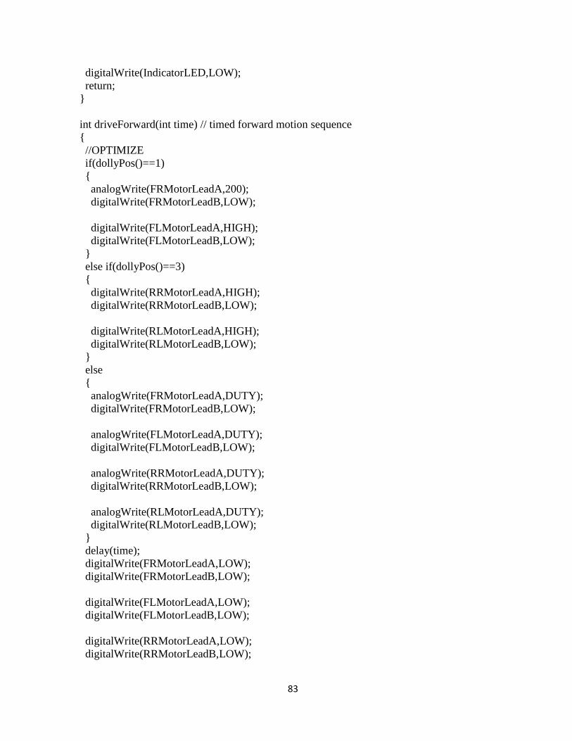
83
digitalWrite(IndicatorLED,LOW);
return;
}
int driveForward(int time) // timed forward motion sequence
{
//OPTIMIZE
if(dollyPos()==1)
{
analogWrite(FRMotorLeadA,200);
digitalWrite(FRMotorLeadB,LOW);
digitalWrite(FLMotorLeadA,HIGH);
digitalWrite(FLMotorLeadB,LOW);
}
else if(dollyPos()==3)
{
digitalWrite(RRMotorLeadA,HIGH);
digitalWrite(RRMotorLeadB,LOW);
digitalWrite(RLMotorLeadA,HIGH);
digitalWrite(RLMotorLeadB,LOW);
}
else
{
analogWrite(FRMotorLeadA,DUTY);
digitalWrite(FRMotorLeadB,LOW);
analogWrite(FLMotorLeadA,DUTY);
digitalWrite(FLMotorLeadB,LOW);
analogWrite(RRMotorLeadA,DUTY);
digitalWrite(RRMotorLeadB,LOW);
analogWrite(RLMotorLeadA,DUTY);
digitalWrite(RLMotorLeadB,LOW);
}
delay(time);
digitalWrite(FRMotorLeadA,LOW);
digitalWrite(FRMotorLeadB,LOW);
digitalWrite(FLMotorLeadA,LOW);
digitalWrite(FLMotorLeadB,LOW);
digitalWrite(RRMotorLeadA,LOW);
digitalWrite(RRMotorLeadB,LOW);
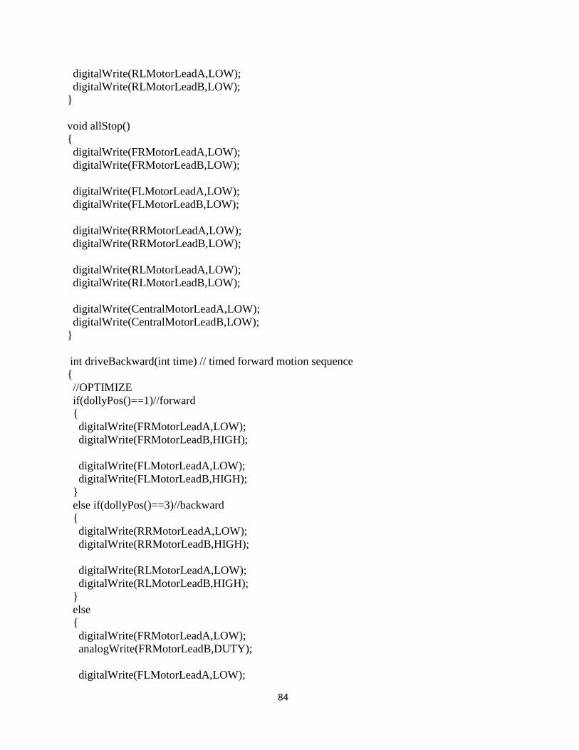
84
digitalWrite(RLMotorLeadA,LOW);
digitalWrite(RLMotorLeadB,LOW);
}
void allStop()
{
digitalWrite(FRMotorLeadA,LOW);
digitalWrite(FRMotorLeadB,LOW);
digitalWrite(FLMotorLeadA,LOW);
digitalWrite(FLMotorLeadB,LOW);
digitalWrite(RRMotorLeadA,LOW);
digitalWrite(RRMotorLeadB,LOW);
digitalWrite(RLMotorLeadA,LOW);
digitalWrite(RLMotorLeadB,LOW);
digitalWrite(CentralMotorLeadA,LOW);
digitalWrite(CentralMotorLeadB,LOW);
}
int driveBackward(int time) // timed forward motion sequence
{
//OPTIMIZE
if(dollyPos()==1)//forward
{
digitalWrite(FRMotorLeadA,LOW);
digitalWrite(FRMotorLeadB,HIGH);
digitalWrite(FLMotorLeadA,LOW);
digitalWrite(FLMotorLeadB,HIGH);
}
else if(dollyPos()==3)//backward
{
digitalWrite(RRMotorLeadA,LOW);
digitalWrite(RRMotorLeadB,HIGH);
digitalWrite(RLMotorLeadA,LOW);
digitalWrite(RLMotorLeadB,HIGH);
}
else
{
digitalWrite(FRMotorLeadA,LOW);
analogWrite(FRMotorLeadB,DUTY);
digitalWrite(FLMotorLeadA,LOW);

85
analogWrite(FLMotorLeadB,DUTY);
digitalWrite(RRMotorLeadA,LOW);
analogWrite(RRMotorLeadB,DUTY);
digitalWrite(RLMotorLeadA,LOW);
analogWrite(RLMotorLeadB,DUTY);
}
delay(time);
digitalWrite(FRMotorLeadA,LOW);
digitalWrite(FRMotorLeadB,LOW);
digitalWrite(FLMotorLeadA,LOW);
digitalWrite(FLMotorLeadB,LOW);
digitalWrite(RRMotorLeadA,LOW);
digitalWrite(RRMotorLeadB,LOW);
digitalWrite(RLMotorLeadA,LOW);
digitalWrite(RLMotorLeadB,LOW);
}
int turnRight(int angle) // timed forward motion sequence
{
//OPTIMIZE
int time = angle*53;
if(dollyPos()==1)//forward
{
digitalWrite(FRMotorLeadA,LOW);
digitalWrite(FRMotorLeadB,HIGH);
digitalWrite(FLMotorLeadA,HIGH);
digitalWrite(FLMotorLeadB,LOW);
}
else if(dollyPos()==3)//backward
{
digitalWrite(RRMotorLeadA,LOW);
digitalWrite(RRMotorLeadB,HIGH);
digitalWrite(RLMotorLeadA,HIGH);
digitalWrite(RLMotorLeadB,LOW);
}
else
{
digitalWrite(FRMotorLeadA,LOW);
digitalWrite(FRMotorLeadB,HIGH);

86
digitalWrite(FLMotorLeadA,HIGH);
digitalWrite(FLMotorLeadB,LOW);
digitalWrite(RRMotorLeadA,LOW);
digitalWrite(RRMotorLeadB,HIGH);
digitalWrite(RLMotorLeadA,HIGH);
digitalWrite(RLMotorLeadB,LOW);
}
delay(time);
digitalWrite(FRMotorLeadA,LOW);
digitalWrite(FRMotorLeadB,LOW);
digitalWrite(FLMotorLeadA,LOW);
digitalWrite(FLMotorLeadB,LOW);
digitalWrite(RRMotorLeadA,LOW);
digitalWrite(RRMotorLeadB,LOW);
digitalWrite(RLMotorLeadA,LOW);
digitalWrite(RLMotorLeadB,LOW);
}
int turnLeft(int angle) // timed forward motion sequence
{
//OPTIMIZE
int time = angle*53;
if(dollyPos()==1)//forward
{
digitalWrite(FRMotorLeadA,HIGH);
digitalWrite(FRMotorLeadB,LOW);
digitalWrite(FLMotorLeadA,LOW);
digitalWrite(FLMotorLeadB,HIGH);
}
else if(dollyPos()==3)//backward
{
digitalWrite(RRMotorLeadA,HIGH);
digitalWrite(RRMotorLeadB,LOW);
digitalWrite(RLMotorLeadA,LOW);
digitalWrite(RLMotorLeadB,HIGH);
}
else
{
87
digitalWrite(FRMotorLeadA,HIGH);
digitalWrite(FRMotorLeadB,LOW);
digitalWrite(FLMotorLeadA,LOW);
digitalWrite(FLMotorLeadB,HIGH);
digitalWrite(RRMotorLeadA,HIGH);
digitalWrite(RRMotorLeadB,LOW);
digitalWrite(RLMotorLeadA,LOW);
digitalWrite(RLMotorLeadB,HIGH);
}
delay(time);
digitalWrite(FRMotorLeadA,LOW);
digitalWrite(FRMotorLeadB,LOW);
digitalWrite(FLMotorLeadA,LOW);
digitalWrite(FLMotorLeadB,LOW);
digitalWrite(RRMotorLeadA,LOW);
digitalWrite(RRMotorLeadB,LOW);
digitalWrite(RLMotorLeadA,LOW);
digitalWrite(RLMotorLeadB,LOW);
}
Appendix B
PROCESSING 2.0 program ‘Direct Keyboard Control’
import processing.serial.*;
Serial myPort;
void setup () {
String portName = Serial.list()[0];
myPort = new Serial(this, Serial.list()[0], 9600);
}
void keyPressed()
{
switch (key) {
case 'w':
myPort.write("w");
break;

88
case 's':
myPort.write("s");
break;
case 'a':
myPort.write("a");
break;
case 'd':
myPort.write("d");
break;
case 'f':
myPort.write("f");
break;
case 'c':
myPort.write("c");
break;
case 'r':
myPort.write("r");
break;
case ' ':
myPort.write(" ");
break;
default:
break;
}
}
void draw() {
// if (keyPressed == true) {
// if (key == 'w' || key == 'W') {
// myPort.write("w");
// }
// if (key == 's' || key == 'S') {
// myPort.write("s");
// }
// if (key == 'a' || key == 'A') {
// myPort.write("a");
// }
// if (key == 'd' || key == 'D') {
// myPort.write("d");
// }
// if (key == 'c' || key == 'C') {
// myPort.write("c");
// }
// if (key == 'f' || key == 'F') {
// myPort.write("f");
// }
// if (key == 'r' || key == 'R') {
89
// myPort.write("r");
// }
// if (key == ' ' || key == ' ') {
// myPort.write(" ");
// }
// }
// else {
// myPort.write(" ");
// }
}

90

91

92

93

94

95
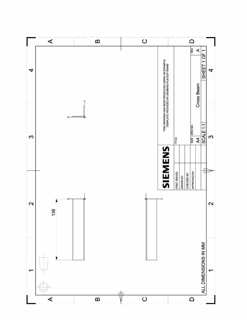
96

97