development graphite/ polyimide honeycomb core materials · 2013-08-31 · of honeycomb panel...
TRANSCRIPT
Development of Graphite/ & Polyimide Honeycomb Core Materials -
R. H. Stone
LOC KHE ELI - CAL I FO RN I A C W A N v Burbsnk , CA 9’1520
SEPTE3fBER 1578
https://ntrs.nasa.gov/search.jsp?R=19780025205 2020-04-12T14:31:22+00:00Z

Page
S.RY . . . . . . . . . . . . . . . . . . . . . . . . . . . . . . . . 1
INTRODUCTION . . . 0 . 0 0 0 . 3
PolyimideRes ins .......................... 4
Fiber Reinforcements ........................ 5
TECHNICAL APPROACH . . . . . . . . . . . . . . . . . . . . . . . . . . . 7 Task 1 . Graphite/Polyinide Honeyccmb Core Development with F-l78/T300 and NR-l5012:a2/T300 Material S e l e c t i o n . . . . . . . . . . 7
F-l78/T300 development ..................... 8
NR-l50A2:B2/T300 material and processing development . . . . . . 9
NR-l50A2:B2/T300 panel fabr ica t ion and testing . . . . . . . . . 12 Task 2 . Graphite/Polyimide Honeycomb Core Development with NR-150B2/W-S and PnR-15/W-S Material S e l e c t i o n . . . . . . . . . . . 13
Fabric development . . . . . . . . . . . . . . . . . . . . . . . 14 PMR-15 process development . . . . . . . . . . . . . . . . . . . 15 NR-150B2 process dmelopment . . . . . . . . . . . . . . . . . . 16 LAX-13 bonding de:relopment . . . . . . . . . . . . . . . . . . . 18 Testing . . . . . . . . . . . . . . . . . . . . . . . . . . . . . 19
DISCUSSION OF 3ESULTS . . . . . . . . . . . . . . . . . . . . . . . . . . 20
NR-l50A2:B2/T300 Results . . . . . . . . . . . . . . . . . . . . . . 20
PHP-l5/Hhi-S Test Resul ts . . . . . . . . . . . . . . . . . . . . . . 23
NR-l5OB2/HMS Test Results . . . . . . . . . . . . . . . . . . . . . 25
LARC-l3 Test Resul ts . . . . . . . . . . . . . . . . . . . . . . . . 26
CONCLUSIONS . . . . . . . . . . . . . . . . . . . . . . . . . . . . . . . 28 REFFilENCES . . . . . . . . . . . . . . . . . . . . . . . . . . . . . . . 30
T8ble
1
9
10
11
12
13
14
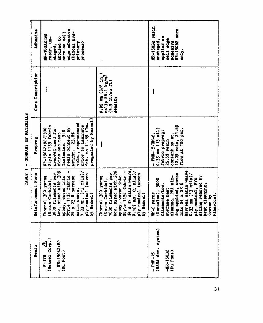
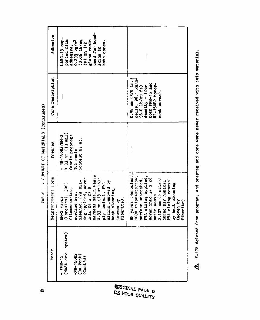
S u r a r y o f l h t e r i a l s ...................... 31
TestOutl ine .......................... 33
Test Outl ine . Optimization of Graphlte/Polyi.lde Laminates . . . 34
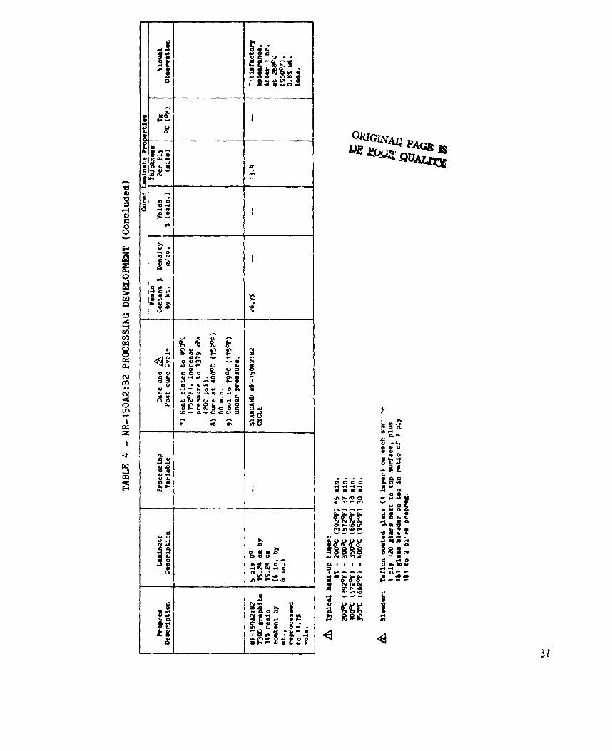
NR-150A2:W Processing Development . . . . . . . . . . . . . . . 36
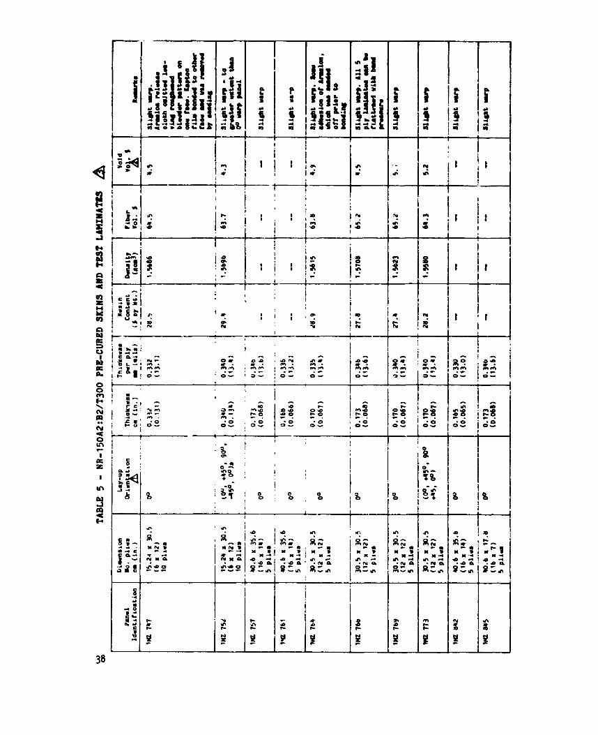
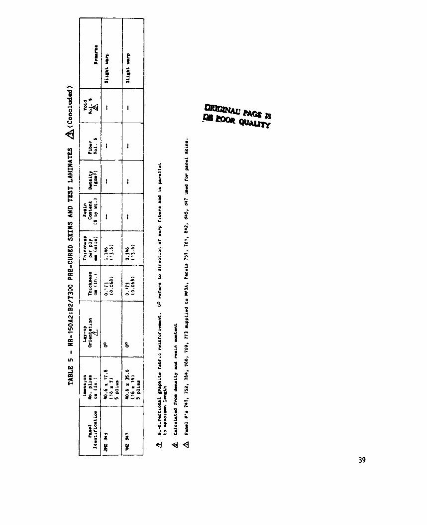
NR-lSOA2:B2/T300 Pre-Cured Skins and Test Laminates 38
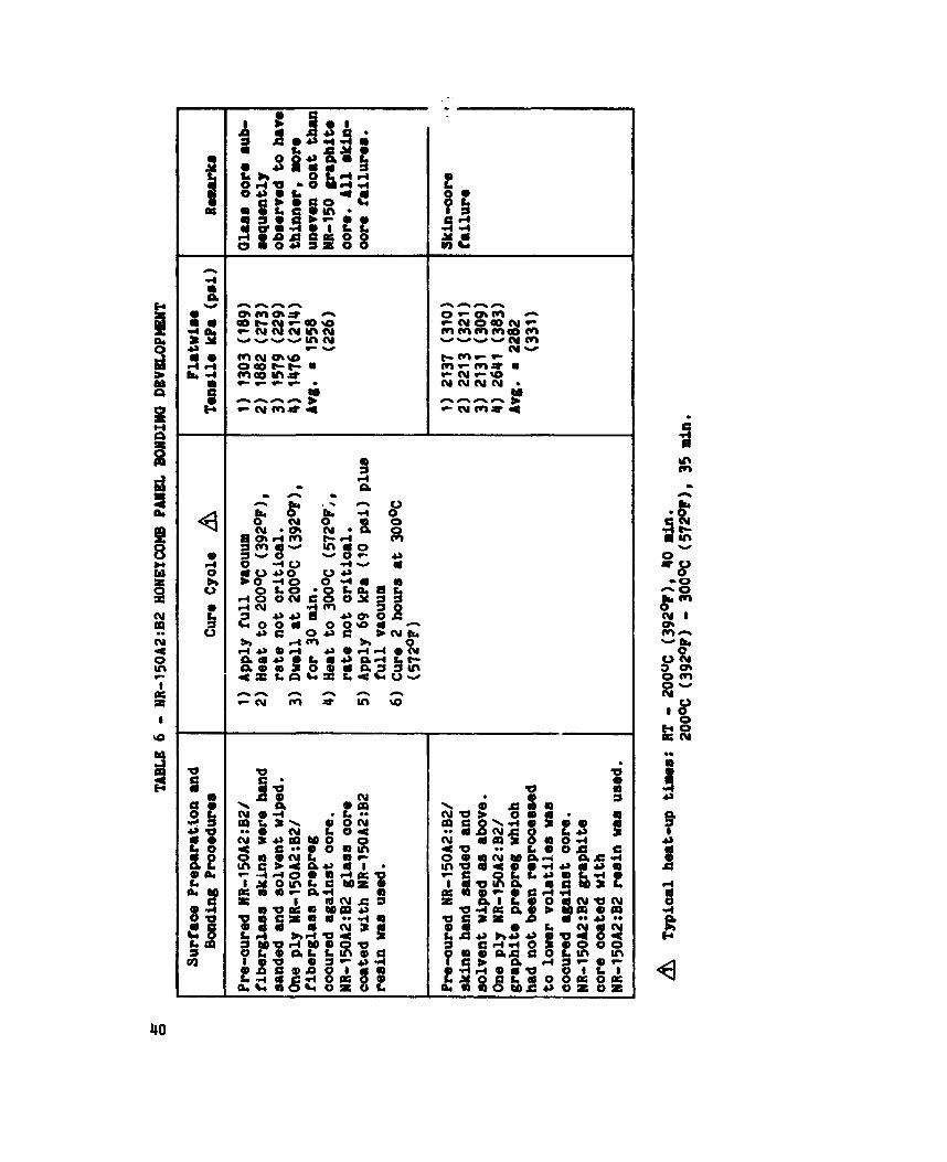
NR-15OA2:W Honeycomb P a n e l Bondin& Davelopmemt 40
. . . . . . . . . . . . . . . .
PW-15 Processing Developaent . . . . . . . . . . . . . . . . . . 41
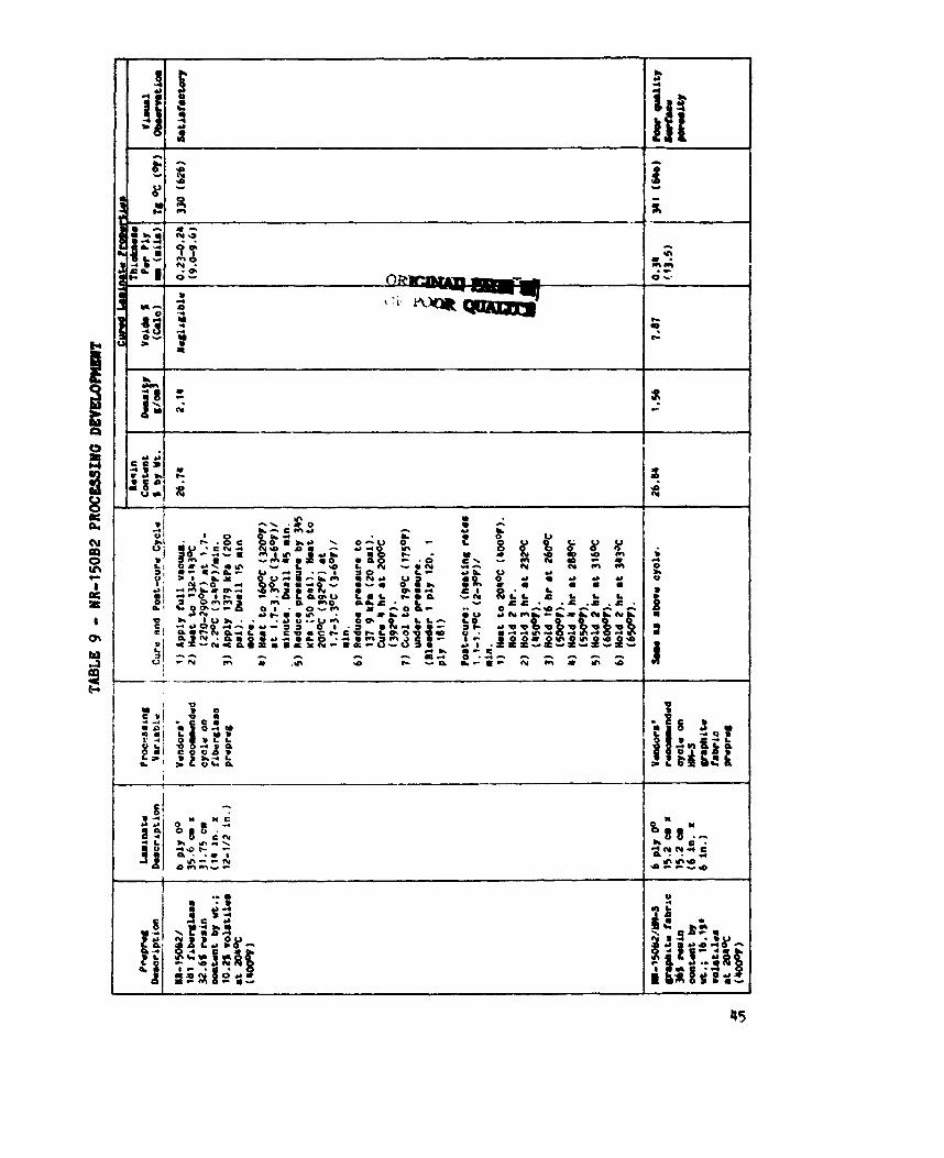
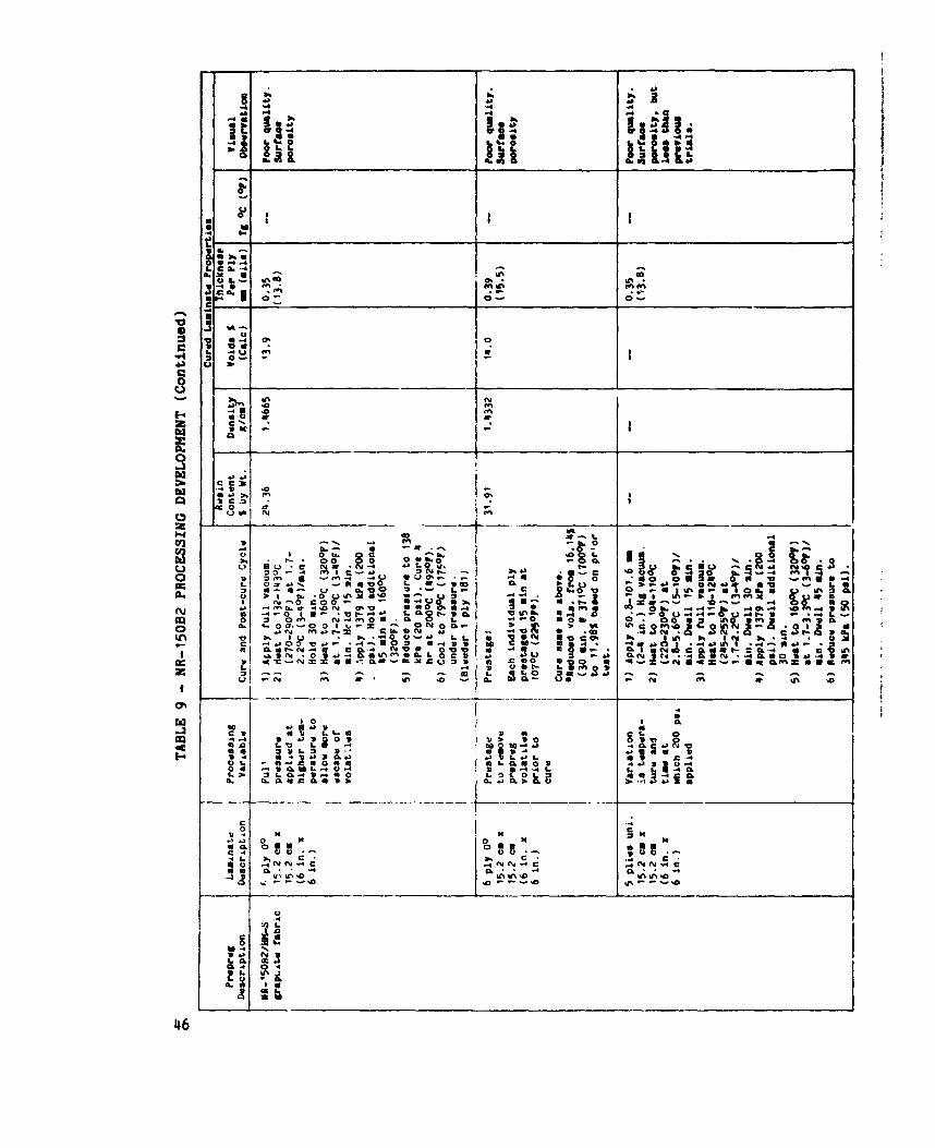
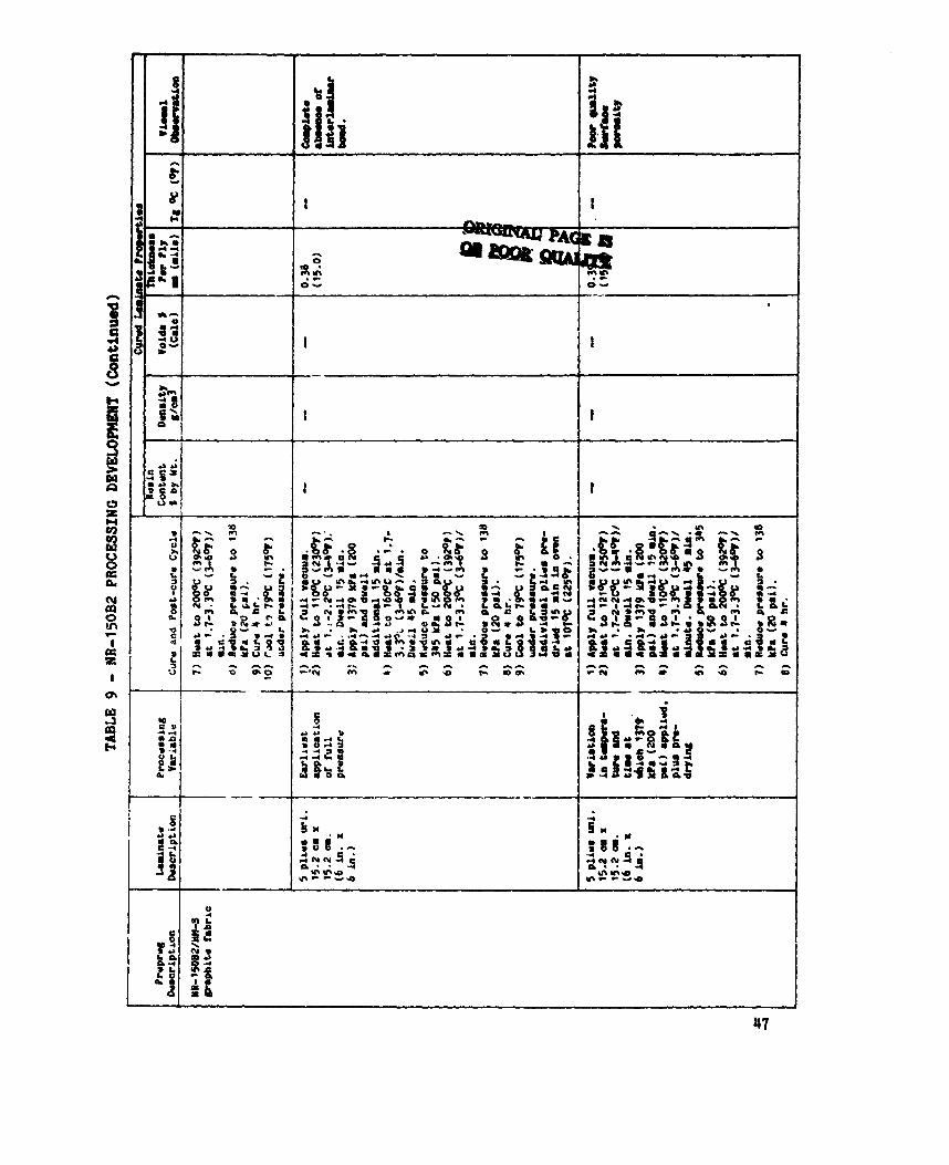
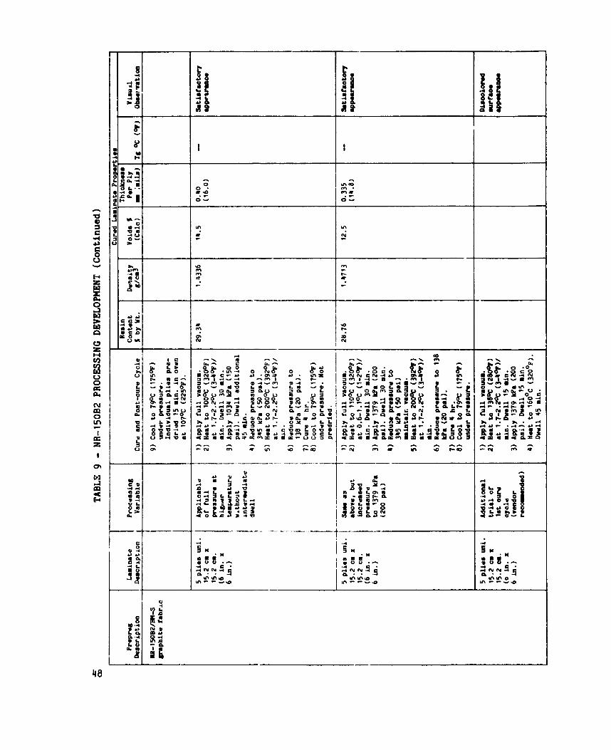
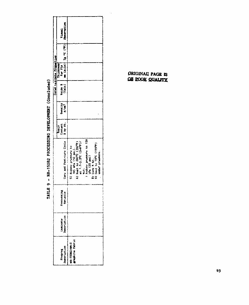
NR-150B2 Processing Development . . . . . . . . . . . . . . . . . 45
P H R - l S / ~ S Pre-Cured Skin and Test Laminates . . . . . . . . . . 44
LARC-13 Bonding Develepment . . . . . . . . . . . . . . . . . . . 50
Test Resul t s . NR=lSOA2:B2/T300 Sandwich Panel Specimens . . . . 52
Test Results of NR-l50A2:B2 Specimens and Loading B l o c k 8 Re-Bonded w i t h LARC-13 ..................... 54
PHR-lS/HHS Sandwich Panel Test Resul ts . . . . . . . . . . . . . 55
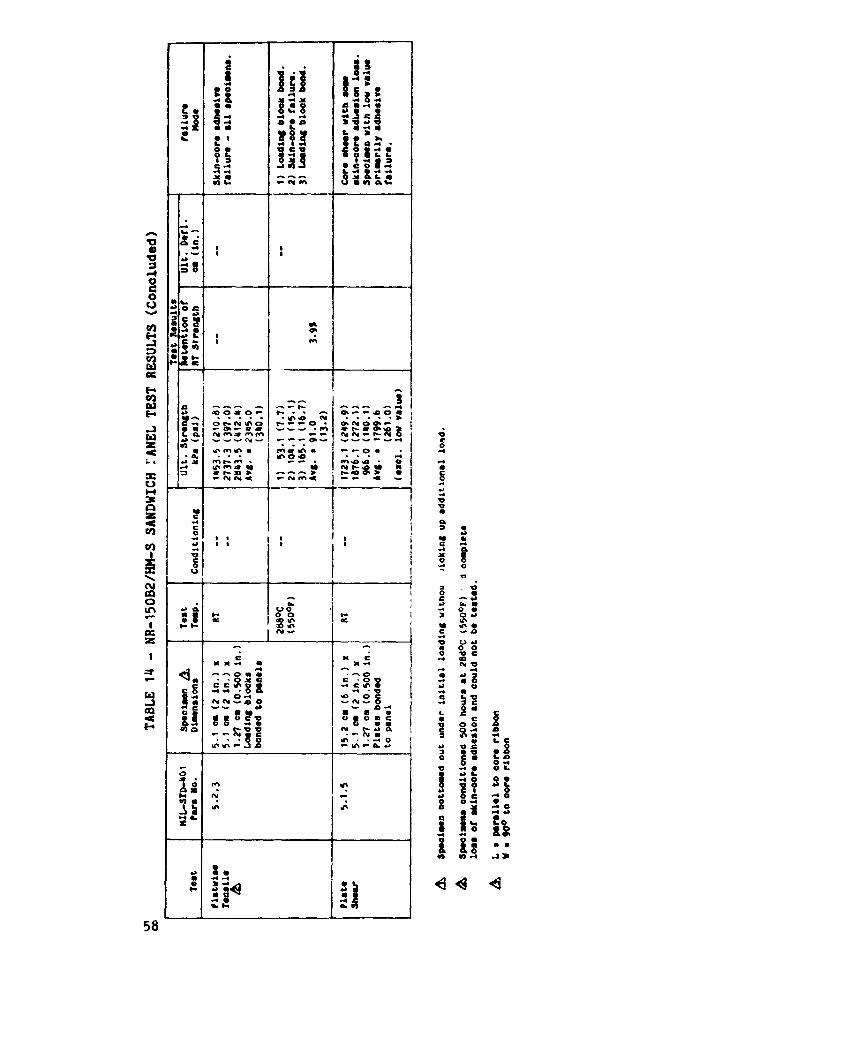
NR-lSOB2/IP1-S Sandwich Panel P e s t Results . . . . . . . . . . . . 57
l v
LIST OF FIGURES
5
6
7
8
Graphite honeycab core shear strength iRT) . . . . Graphite honeycomb core shear nodulus (RT) . . . . . . Graphite/polyinide honeycmb core . . . . . . . . . . . Diagram of heated platen . . . . . . . . . . . . . . . Heated platen with lead wires . . . . . . . . . . . . . PKR-IEj/HH-S laminates . . . . . . . . . . . . . . . . . Platwise tensile specimens bonded wlth LARC-13 adhe8iVe
Plate shear specimens showing par t ia l core fallurss .,
. . . .
. . . .
. . . .
. . . . 0 . . e
9 0 - 0
. . . .
. . . .
pace
. 59 60
. 61
. 62
. 63 64
. 65
. 65
V
DEVELOPlBNT OF GRAPHIl'B/POLYI!4IDE HONEYcollB CORE HATKRIALS
Robert H. Stone
Lockheed-California Company Burbank, California
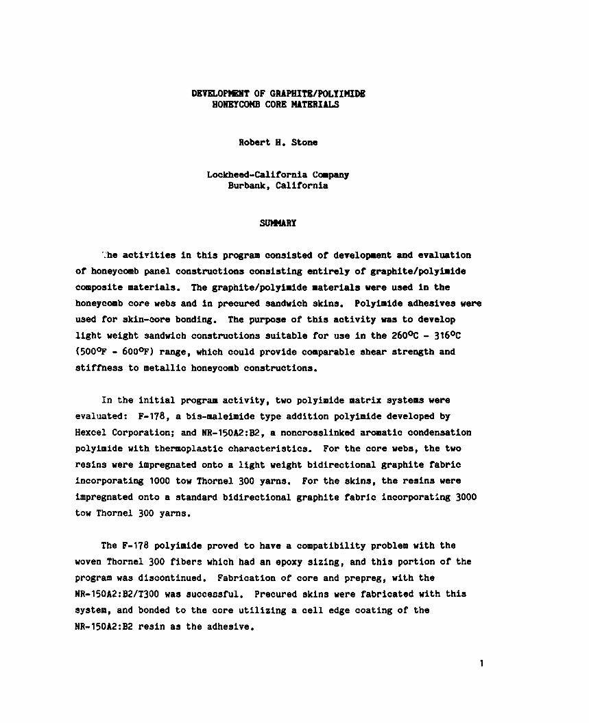
SUWARY
':he activities in this program consisted of development and evaluation of honeycomb panel constructions consisting entirely of graphite/polyimide composite materials. honeycomb core webs and in precured sandwich skins. used for skin-core bonding. light weight sandwich constructions suitable for use in the 26OoC - 316OC (500- - 6000F) range, which could provide comparable shear strength and stiffness to metallic honeycomb constructions.
The graphite/polyimide materials were used in the Polyimide adhesives w e m
The purpose of this activity was to develop
In the initial program activity, two polyimide matrix systems were F-178, a bis-maleimide type addition polyimide developed by evaluated:
Hexcel Corporation; and NR-l50A2:B2, a noncrosslinked aromatic condensation polyimide with thermoplastic characteristics. For the core webs, the two resins were impregnated onto a light weight bidirectional graphite fabric incorporating 1000 tow Thornel 300 yarns. For the skins, the resins were impregnated onto a standard bidirectional graphite fabri.c incorporating 3000 tow Thornel 300 yarns.
The F-178 polyimide proved to have a compatibility problem with the woven Thornel 300 fibers which had an epoxy sizing, and this portion of the program was discontinued. Fabrication of core and prepreg, with the NR-l50A2:B2/T300 was successful. Precured skins were fabricated with this system, and bonded to the core utilizing a cell edge coating of the NR-l50A2:B2 resin as the adhesive.
1
The NR-l50A2:W/T300 pauel constructions were tested at roo.
temperature, and at 288% (55OoF) before and after 288% (550OF) wing. test results indicated that the graphite honeyocmb construotion provide8 generally comparable mechanical properties to metallio honeycomb oonstruo- tionsb The NR-l50A2:B2/T300 system appeared to be acceptable, but somewhat marginal for 288% (550°F) use.
The
The next phase of the program continued the graphite/polyimide honeywmb development with two additional systaw; NR-1SOB2, a more thermally stable version of the NR-150 type polyimides; and PMR-15, a NASA developed addition polyimide which utilizes three commercially available monomers. To avoid the compatibility problems encountered with the sired Thornel 300, and to provj f
a more thermally stable fiber, HM-S fibers were used In the form of bidirectional woven fabrics for both the core webs and the skins. These H)I-S
fabrics were a recent development. weaving which was subsequently removed by heat cleaning.
The fabrics had a PVA siring used for
Honeycomb core, prepreg, and sandwich panels were fabrioated with these A recently developed polyimide adhesive, LARC-13, was utilized two systems.
as the skin-core adhesive. modification of the PHR-15 system. precured skins were of less than optimum quality, because of thermal mimatch with the PMR-15/HM-S system which caused resin cracks, and a void problem with the NR-150B2. 288OC (550°F) was a marginal use temperature for the PEIR-15 and LARC-13 systems.
LARC-13 was developed by NASA, and is a In both cases, the gra, .ite/polyimide
Testing of the sandwich constructions indioated that
The NR-150B2 system proved more satisfactory for 288% (550°F) use.
Development and fabrication of the grephitw'polyimide core was performed by Hexcel Corp., Dublin, California under the direotlon of Juan Chorne.
2
High temperature composite systems incorporating thermally stable graphite fibers Pnd polyimide resins appear to have widespread applicability for advanced vehicles, such as supersonic aircraft, which require the combination of high performance, light weight, and thermal stability these materials offer. is in honeycomb sandwich constructions which for many applications provides the most structurally efficient and lowest weight design concept.
An effective meaqs of utilizing graphite/polyimide systems
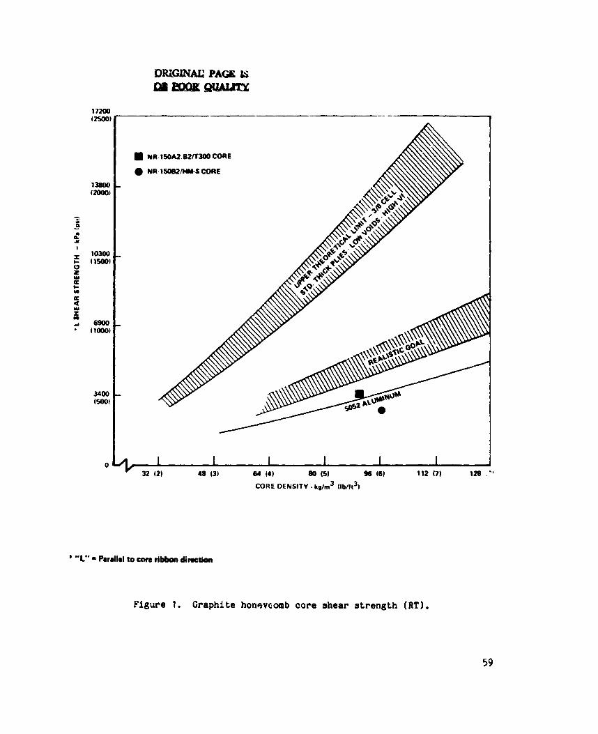
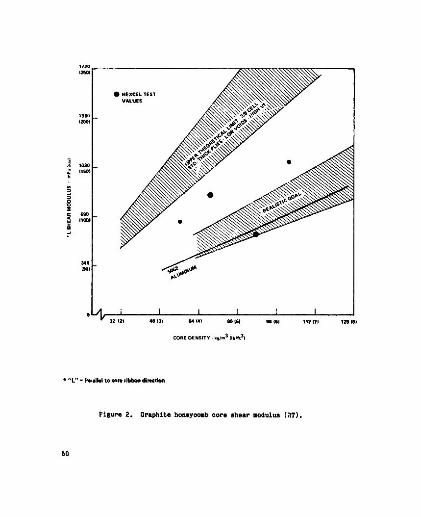
The use of graphite composite as a honeycoab core material provides for the first time a nonmetallic core construction cap.de of matching the specific core shear strength and stiffness properties of metallic cores (Figs. 1 and 2). The most effeative graphite construction to provide these properties is the use of continuous fiber reinforcements in the web oriented on the bias (~450) to the core thickness. honeycomb constructions have been their sensitivity to corrosion, but available nonmetallic fiberglass and nylon paper cores cannot be substituted in many of the more highly loaded components in which metallic core has been used, because of their low core shear strength and stiffness. honeycomb provides the necessary match of properties to metallic honeycomb, and with composite skin3 effectively eliminates corrosion as a service problem. limit its use as a substitute for aluminum core in applications for the stdndard temperature range up to 177OC (350°F).
Thc; chief problem with aluminum
Graphite
Despite this advantage, the costs of graphite core will probably
In the higher tempei'ature applications, in supersonic applications hhere use temperatures will range up to 316OC (6OO0F), graphite core incorporating polyimide resins would be substituted for the relatively expensive titanium brazed honeycomb constructions. For these applications, graphite core would be more likely to show cost effectiveness, and for been placed on development of graphite honeycomb cere for higher temperature applications.
.Is reason emphasis has
3
Polylalde Resins
An extensive amount of development work has been accomplished over the last several years on new polyimido resins for use in the range frcm 232OC
(4500F) to 316% (6000F), and several new polyimide systems have beoome available for incorporation in this program. The origincl condensation polyimides, while providing excellent themal stability up to 316OC (600OF) , were extremely difficult to process beoause of the nature of the condenaation reaction which proiuced volatile by-products during the polymerization reaction. resultant adverse effects on mechanical properties, fatigue life, and durability.
This also resulted in relatively high void content laminates with
The development of polyimide formulations which polymerized or "imidized" with addition reactions eliminated this problem and greatly improved processability of the system, but with some lcss of thermal stability. The bis-naleimide type addition polyimides, 9f which Hexcel's F-178 is an example, provides ease of processing approachi?g that of epoxies and can be cured at 177% (35OOF). of 232OC (450°F) can be achieved.
With proper post-cure a use temperature
For applications in the 232OC - 316OC (450°F - 60O0F) range, other new systems have been developed to provide a more optimum balance of processabil- ity and thermal stability. The NR-150 polyimide systems developed by Du Pont incorporate a very thermally stable, highly aromatic polymer structure produced through a condensation reaction. (Ref. 1) The polymer chains in the NR-150 systems do not cross-link, however. This produces a noncrystalline material with thermoplastic characteristics capable of melt flow above the glass transition temperature (Tg), More significantly for processing, the absence of cross-linking permits the removal of volatile condensation products and residual solvent by means of an oven post-cure.
Another new polyimide is the PMR-15 system developed by NASA. This is an addition polyimide prodr'ed through the reaction of three commercially
4
available monomers in a mixture with ethanol solvent. (Ref. 2) One of the monomers, a monomethyl eater of a difunctional acid (NE), provides end-caps for a low m1lecular weight prepolymer chain produced in the initial addition reaction. cross-linking reaction which produces the final cured resin. advantages of void-free reactions, production from readily available monomeric reactants, and a high degree of thermal stability provided by the pulymeric structure.
Upon further application of heat, the end-caps open to produce the PHR-15 provides
Relatively few polyimide film adhesives have become available since development of the condensation systems. NASA is a modification of the PMR-15 chemistry in which one of the three monomers, methylene-dianiline (HDA) , is replaced with another amine system to provide improved adhesion characteristics. This system, called LARC-13, is available as a supported film adhesive.
An adhesive recently developed by
Fiber Reinforcements
The Statement of Work for this program specified the use of graphite fabric reinforcement. provided a distinct .dvantage, in that fabric prepreg with its greater integrity in the unm*ed form, could be adapted to the expansion process of core fabrication i r . r:hich the core is expanded into the hexagonal shape after bonding the nodes in the correct pattern on the flat sheet webs. graphite tape webs would have to be fabricated using the more expensive corrugation process in which the nodes are bonded after the webs have been formed into the corrugated shape.
For the hmeycomb core webs, the use of woven fabric
Core with
The ilse of fabric severely limited the salection of graphite fiber reinforcenent. available graphite fabric utilized Thornel 300. Thornel 300 has relatively poor thermal-oxidative stability as compared to higher modulus graphite fibers, such as HT-S or HM-S (Ref. 31, bat available data (reported verbally to Lockheed) indicated that Thornel 300 provided acceptable properties up to
At the time this program was Initiated, the only readily
5
the 260OC - 288% (500°F - 550*) range when encapsulated in a thermally stable polyimide matrix. epoxy sizing. which varies in content from 0.3% to 2% on the fiber, and was the sizing used in the above mentioned specimens where acceptable elevated temperature properties were obtained. polyimide sizing, but only at a very high premium cost.
Thornel 300 is available commercially only with an This sizing, designated 309, is an uncatalyzed epoxy resin
Thornel 300 was at that time available with a
At the time the second task of the program was initiated, a new family of woven graphite fabrics had been developed utilizing HkS graphite. HH-S
is a high modulus 3.86 x 10⁵ W a (56 x lo6 psi nominal) fiber which because of its high processing temperature and high degree of graphitization has much greater thermal stability than Thornel 300. available only in 10,000 filament tows which were unsuitable for weaving. The recent development of 3000 and 1000 filament tows made possible the development of standard and light weight bidirectional woven fabrics suitable for skins and honeycomb core respectively. with a heat cleaned surface for prepreg tapes. PVA sizing is required, and this must be removed after weaving by heat cleaning, is its t*elatively low strength, low strain to failure, and brittle characteristics as compared to the lower modulus fibers such as Thornel 300. HM-S is also a more expensive fiber, t.,t the availability of a thermally stable fiber in fabric form appeared to outweigh potential disadvantages.
HH-S had previously been
HM-S is used without sizing but For the weaving operation, a
This is one potential problem, but a more basic drawback with HM-S
It should ba noted that the Celion graphite fibers, reported to have comparable mechanical propeities, weavability, and costs to Thornel 300 but with greatly improved thermal stability, were not available at the time the second task of the program was initiated. obvious choice as a fiber reinforcement for this program had it been available.
This fiber would have been an
6
TECHNICAL APPROACH
Task 1 - Craphite/Polyimide Honeycomb Core Development wi th
F-l78/T300 and NR-l50A2:82/T300 Material S e l e c t i o n
For t h e i n i t i a l program on graphi te /poly imide honeycomb core and panel development , two r e c e n t l y developed polyimides were selected: bis-maleimide type polyimide, and Du Pont ' s NR-l50A2:B2 polyimide. These systems are d iscussed more f u l l y i n Sec t ion 1 of t h i s r e p o r t . selected to provide optimum p r o c e s s a b i l i t y for t h i s program because o f its c a p a b i l i t y of being cured a t 177OC (35OOF) using cure procedures comparable to epoxy cure cycles. thermal s t a b i l i t y compared t o o t h e r systems.
Hexcel's F-178
F-178 was
It was recognized t h a t F-178 would be l i m i t e d i n
NR-l50A2:B2 was selected t o provide an optimum thermal s t a b i l i t y i n t h e
260% - 288OC (500°F - 550°F) range.
r e s i n s of t h e NR-150 series, NR-150A2 and NR-150B2. NH-150A2 has a glass
t r a n s i t i o n temperature (Tg) o f 28OoC - 3OO0C (536OF - 572OF1, and r e q u i r e s a pnocessing temperature of approximately 343OC (650°F) , providing a maximum
use temperature o f 26OoC (500°F). - 700°F) and a processi:ig temperature o f ?round 427OC (800°F), providing a
m a x i m u m use temperature o f 343OC (65O0F). i n t e rmed ia t e Tg , process ing , and use temperatures (322OC C61 1°F: , 3Il0C
[700°F3 and 2dU°C [550°F1 r e s p e c t i v e l y ) , and was selected as optimum f o r t h i s
program. molding temperatures which are s u f f i c i e n t l y above t h e Tg so t h a t meit f low of
these e s s e n t i a l l y thermoplastic materials can occur . t h e material is e s s e n t i a l l y complete a t 204OC (400OF).
This system is a 50:50 mixture o f two
NR-150B2 has a Tg o f 35OoC - 371OC (662OF
The 50:50 mixture r e s u l t e d i n
It should be noted t h a t t h e above process ing temperatr-es are
The polymerizat ion of
The selected f i b e r re inforcement , as d iscussed i n Sec t ion 1 , was epoxy s i zed Thornel 300 i n two fabric s t y l e s . For the c o r e webs S t y l e 1136 fabric,
a b i d i r e c t i o n a l 34 x 33 s a t i n weave inco rpora t ing 1000 f i l amen t tow T300 yarn was used; f o r t ne prepregs used i n s k i n and test lamina te f a b r i c a t i o n , S t y l e 1133 fabric , a b i d i r e c t i o n a l 24 x 23 s a t i n weave inco rpora t ing 3000 f i lament
7
tow ~ 3 0 0 yarn was used. These fabrics and tne va r ious r e s l n - f i b e r combinations used i n t h e program are summarized and described i n Table 1.
Hexcel Corp. was re spons ib l e f o r material development .In t h i s Task,
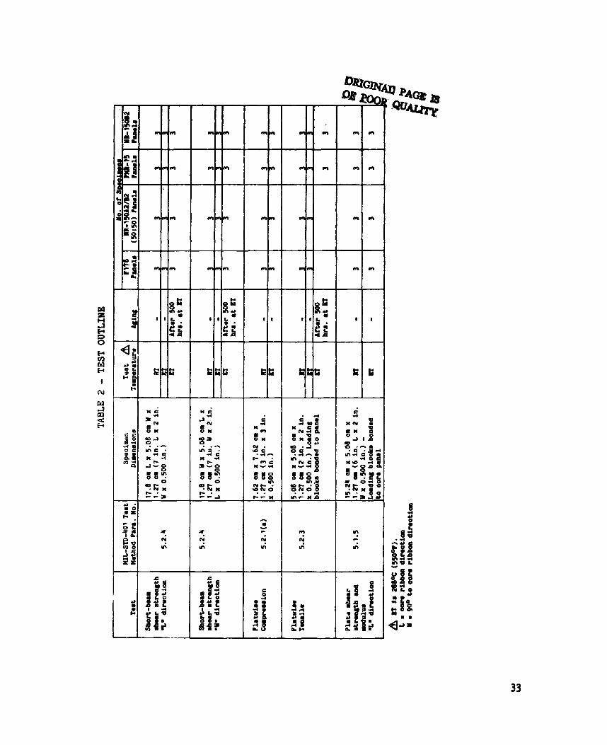
inc luding weaving o f t h e fabrics, prepreg f a b r i c a t i o n , and honeycomb core development and f a b r i c a t i o n . Lockheed was re spons ib l e for precured graphi te /pol yimide s k i n f a b r i c a t i o n , honeycomb panel f a b r i c a t i o n , and testing. The test p l a n , which was i d e n t i c a l f o r both program Tasks is o u t l i n e d i n Table 2. Lockheed a l s o fabricated a ser ies o f test lamina tes and honeycomb test specimens with each material system i n t h i s prog am f o r submi t t a l to NASA.
- /T?OO welo-. - The i n i t i a l a c t i v i t y a t Hexcel, after weaving of t h e fabrics, was a prepregging process ing development w i t h t h e two polyimide r e s i n s . Preliminary mechanical t ea t s were run on lamina tes fabricated from these pre pregs, and t h e r e s u l t s i nd ica t ed a cmpat ibi l i ty problem wi th t h e
F-l7d/T300 system.
strengths of laminates given a 260° (500°F) post-cure ( r e q u i r e d t o i n c r e a s e thermal s t a b i l i t y and use temperature of t h e F-178 system) were observed t o have a 50% reduct ion compared t o lamina tes which only had t h e 177OC (35OOF) i n i t i a l cu re . This i nd ica t ed t ha t short-time exposure t o 26OOC (5000F) s e r i o u s l y degraded lamina te p r o p e r t i e s , and t h e f i b e r - r e s i n i n t e r f a c e bo...+ involving t h e 309 epoxy s i z i n g was considered t o be t h e probable cause of t h i s problem. had not encountered a similar compa t ib i l i t y problem, and as these had been wi th another Thornel 300 ba tch i t was thought t h a t batch v a r i a t i o n s i n f iber
s i z i n g formula t ion , con ten t , or d i s t r i b u t i o n might be the cause.
The problem was noted when room temperature f l e x u r e
Previous work a t Hexcel with F-l78/Thornel 300 tape pre-preg
Micrographic examination o f T300 fiber from d i f f e r e n t batches d i d
i n d i c a t e a v a r i a b i l i t y i n t h e amount of s i z i n g NR-l50A2:B2/T300 system, after c u r e a t 399OC (75OoF), were no t reduced as much as the post-cured F-170 samples i n d i c a t i n g t h a t t h e problem was no t caused by f i be r degrada t ion du r ing post-cure, and t h a t t h e c o m p a t i b i l i t y
problem was specific to F-178.
F lexura l s t r e n g t h s o f t h e
8
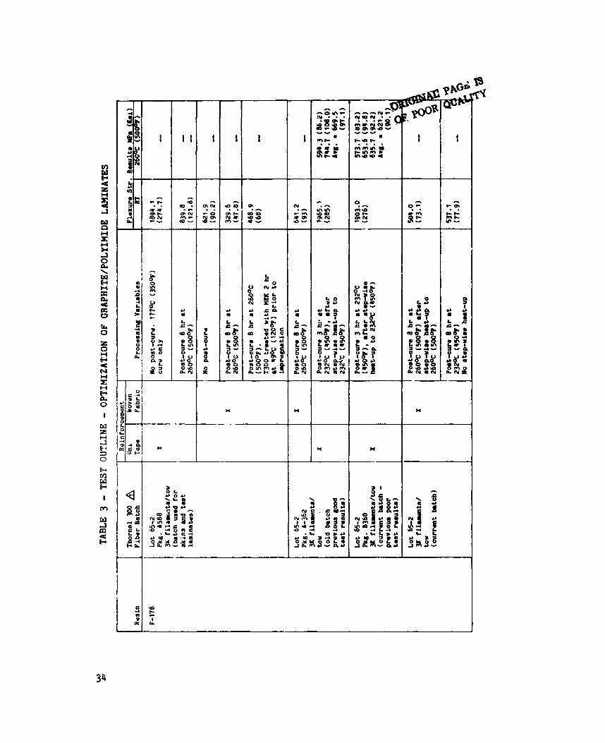
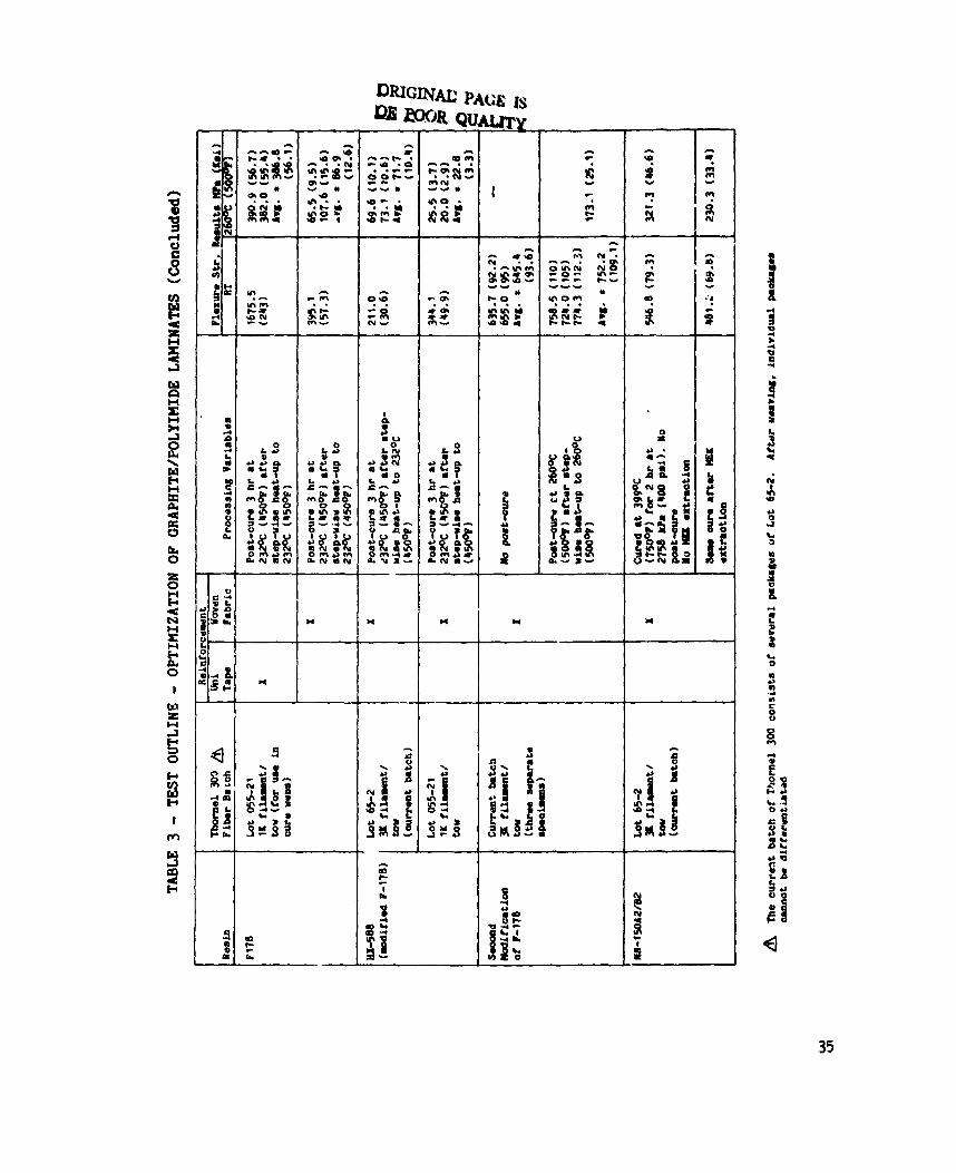
Hexcel's approaoh to resolving this problem inoluded evaluation of different fiber batohes, post-oure variations, resin modlfiaations, and MEU extraction to remove the fiber slz?ng after weaving and prior to impregnation. these variables and tested at RT and 26OOC (500°F). evaluation are given in Table 3, and include data OIL both unidirectional tape specimens and woven fabric specimens.
Flexural specimens were taken from laminates lnoorpmating Results of this
The test results given in Tabi. 3 confirmed a batch variability. MEK extraction resulted in less RT flexural strength reduction after post-cure; and both post-cure variation ( stepwise heat-up with maximum post-cure temperature reduced to 288% [5500F] ) , and F-178 resin modification improved the RT properties. substantial property reductic ...
Flexure tests at 260OC (5000/F), however, revealed a
Hexcel performed additional tests on modified F-l78/T300 laminates under an in-house program (whose results are therefore not reported here), and was a5le to eliminate the loss of RT flexure strength after post-Owe. However, retention of room tamperatura f'exure strength was only 60% at 177OC (350°F) and 3C3 at 232OC i450OF) and the F-l78/Thornel 300 was dropped from the program as the result of a? mutual decision of NASA, Lockheed, and Hexcel. should be noted that; extensive data from other programs have indicated excellent propertie: of the F-178 at temperatures up to 232OC (450°F), and t h a t the problems eL,cov.itered in this program appear related to a specific fit sizinglresin compatibility problem.
It
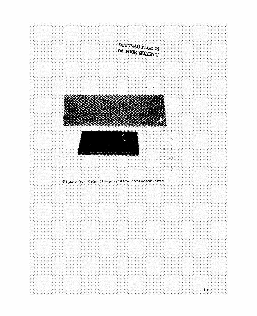
-0- - oessinn dev-. - The program activities on development and fabrication of NR-l50A2:B2/T300 honeycomb core continued, and Hexcel was succe?lsful in fabricating a block of this core with 0.95 om ( 3 1 3 inch) cella and 88.1 kgim3 (5.5 lb/cu ft) density. The core was sliced into 1.27 cm (1/2 in.) segments for testing at Lookheed, and 2.54 om ( 1 in.) slices for submittal to NASA, (Fig. 3 ) .
by the expansion process
9
The core se4pente provided to Lookheed had 8 cell -8 uoating of NR-l50U:B2 resin applied to the cell edges using a proprietary Eexcel prooess. thixotropic additive. specims incorporating prmured NR-15OIgraphite skins which w e r e prepared for bonding by light hand sanding. incorporated a cocured inner ply of the NR-l50U:W/T300 fabric prepreg. This specimen failed at 3568.2 kPa (517.5 psi) while th' specimen without the cocured ply failed at 2223.6 kPa (322.5 pai) .
the combination of the cell edge NR-150 coating and a cocured prepreg ply against the C v e provided a satisfactory skin-core bocd. specimens were fabricated at Hexcel and tested by Lockheed.
The NP-l5OA2:B2 was applied to the cell edges unsta8ed but with a Preiiminary flatwise tensile tests were performed with
Two specimens were bonded, OD8 of which
These results indicated that
The above test
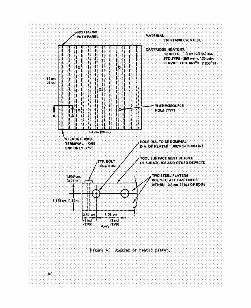
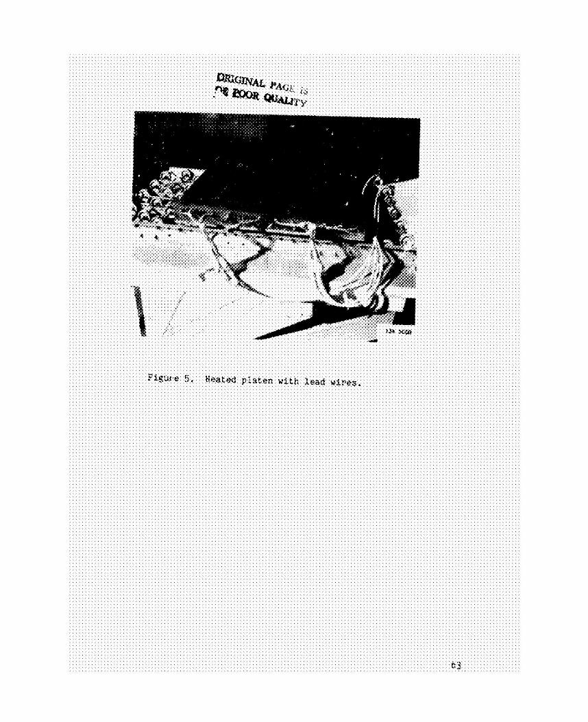
The cure cycle recommended for NR-15OA2:W at that tire by Du Pont required cure temperatures in the 371% - 427% (7009 - 800oF) range, Lockheed's approach for skin fabrication and skin-core bonding was to de-elop an autoclave process. preliminary work at Du Pont indicated that this was an acceptable cure pressure (Rof. 41, even though some rkuction in mechanical properties had to be accepted, as compared to press cured laminates processed at much higher pressures. operating temperature of 316% (60091, and a Yeated platen was developed to provide the supplemental heating required. and 5 and consisted of two 61 cm x 61 ca (24 in. by 24 in.) steel plates tolted together with machined cavities to accommodate cartridge heaters. Thermocouple holes were drilled frcm the bottom to within 0.32 cm (118 in.) of the top surface to provide temperature readings on the tool surfsce without inserting thermocouples into the laminate. around the edges to provide a 55.9 cm by 55,9 cm (22 in. by 22 in.) tool surface for lay-ups.
This limited cure pressure to 1379 W a (200 psi), but
The 1-boratory autoclave at Lockheed is limited to a maximum
This platen is shown in Figs. 4
The plates were bolted
A trial run was made with the platen to cure a NR-150A2:W laahate. The platen was set on a ceramic (Transite) block and covered with heavy gliss
cloth for insulation. The autoclave was heated to 177OC (35OoF) with the
10
p l a t e n s imultaneously heated to 20O0C (392OF). 177OC (35OoF), the p l a t e n was heated t o a 3OO0C (572OF) dwell and t h e n to t h e
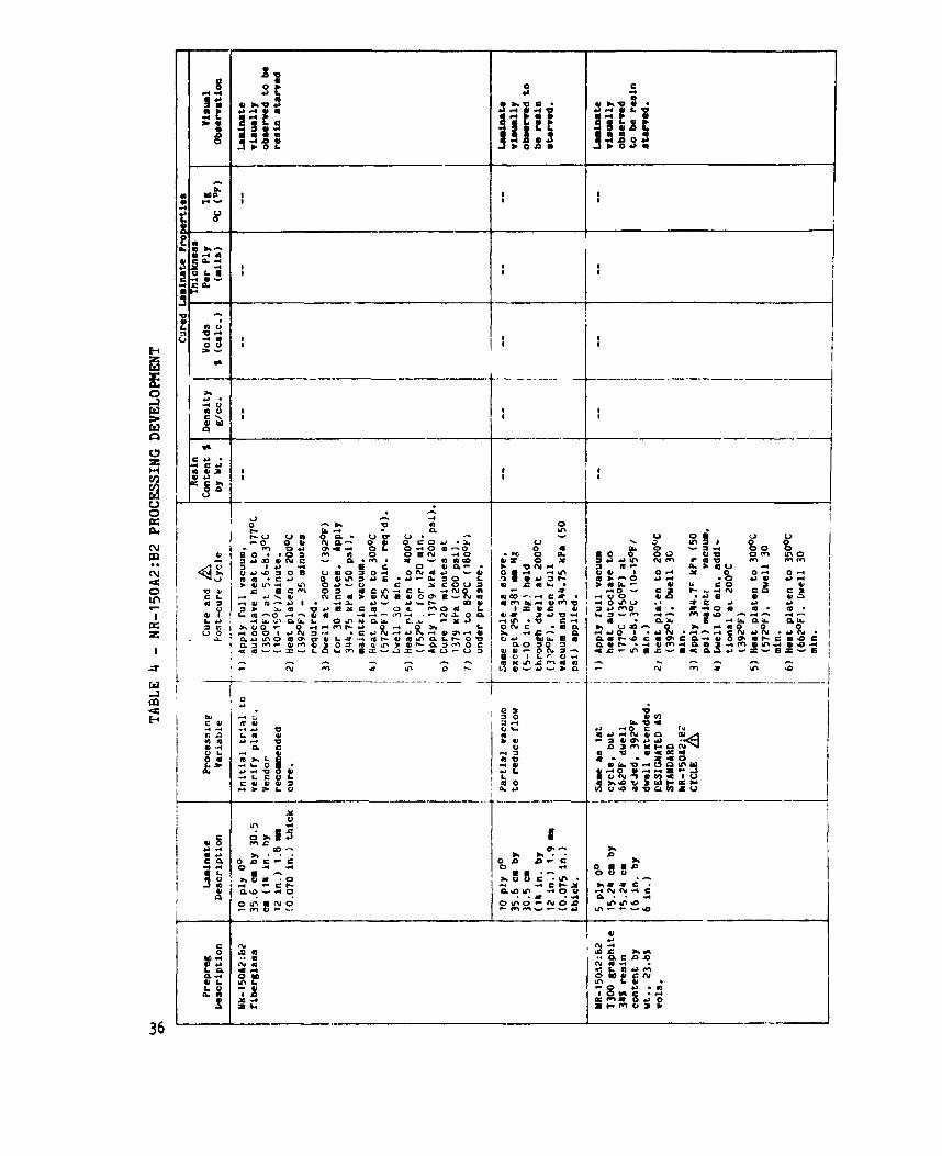
f i n a l awe h p e m t u r e of 400°C (752OF) where it was held for 2 hours under 1379 kPa (200 p s i ) au toc lave pressure. Table 4, and used on NR-l5OA2:82 fiberglass p r e - p r q procured s p e c i f i c a l l y for awe a y o l e development. surface heat-up rates of 7.2°C/min. ( :3°P/mir.ute) f'rom RT t o 200°C (392OF); 3.g°C/min (?°F/min) from 200% (3Y2°F) t o 3OO0C (572OF); and 2.5°C/min. (4.5OF/min.) from 300° (572OF) to 4OO0C (752OF) were a c h i e v F . temperature was held to 4OO0C f~ 5.6oC (752OF The vacuum bag was Kapton film sealed t o the p l a t e n with a one-part s i l i a o n e s e a l a n t , and t h i s bagging system held f u l l vacuum throughout :he c y c l e . t r ial s u c c e s s f u l l y demonstrated the heated p l a t e n approach for high
teaaperature autoc lave processing of t h e NR-150 s y s t s a .
With the 8 U t O C l 8 V O held a t
T h i s awe c y c l e is o u t l h e d f u l l y i n
The heaters were oper8ted a t 150 Volts, and tool
The 100F) for the 2 hours a m .
T h i s
Addit ional trial lamina tes were fabricated using the same cure cyale, which was a Du Pont recommended cycle, on the fiberglass prepreg.
q u a l i t y o f t he fiberglass laminates as determined by v i s u a l examination, r e s i n c o n t e n t , d e n s i t y , and thickness de termina t ions was s a t i s f a o t o r y . T h i s same cure cycle was then used with the NR-l50A2:B2/T300 graphite p r e p r q , and
t h e lamina tes were determined by v i s u a l observa t ion t o be e x c e s s i v e l y s t a r v e d and poor q u a l i t y . These oondl t ions were the r e s u l t of excess ive flow. This prepreg had a v o l a t i l e c o n t e n t i n t h e 20 - 251 range, and t h i s was considered t o be excess ive . Du Pont recommended a v o l a t i l e c o n t e n t i n t he 10 - 12%
range, and prepreg samples were exposed t o v a r i o u s oven d r y i n g c y o l e s t o determine a means of reducl?lg v o l a t i l e c o n t e n t to t h i s l e v e l . minutes a t 143OC (29OoF), w i t h eaah prepreg surface exposed t o c i r c u l a t i n g oven a i r , was found t o reduce t h e v o l a t i l e aonten t to 122. The r o l l of NR-l50AZ:B2/T300 prepreg was s e n t t o a local prepregger, and was processed through their heat ing tower a t 139OC (282OF) for 15 minutes, w i th t h e prepreg a d d i t i o n a l l y experiencing a f i v e minute heat-up and cool-down as it went through t h e heater. This reduced t h e v o l a t i l e s from 23.8% to 11.72 by
weight . Trial lamina tes were fabriaated us ing both t h e Lockheed d r i ed
prepreg and t h e reprocessed prepreg, and t h e r e s u l t s i n d i c a t e d t h a t
The
A c y c l e of 15
11
s a t i s f a c t o r y laminate q u a l i t y was achieved. was 34m (13.4 m i l s ) per p l y for the lamina te made wi th reprocessed prepreg compared to the nominal 34.8 mm (13.7 m i l s ) per ply. t h i s lamiaate was 26.7% by weight which is a r e l a t i v e l y high b u t acceptab le f i b e r loading f o r woven fabric laminate%, Visua l appearance was
s a t i s f a c t o r y , and t h e degree of cure m a v e r i f i e d by de termina t ion of weight l o s s a t 2MoC ( 5 5 O O F ) .
Thickness per p l y for example
Cured r e s i n conten t for
Afier one hour t he laminate los t only 0.8s weight.
. - These r e s u l t s i n d i c a t e d t h i s was a s a t i s f a c t o r y procedure for f a b r i c a t i o n of t h e NR-l50A2:B2/T300 precured sandwich s k i n s and a series of test lamina tes for NASA. runs are o u t l i n e d i n Table 4. A series of s i x lam'-nates were fabricated for
these purposes and were determined t o be a a t i s f a c c o r y i n q u a l i t y and
appearance. These laminates are o u t l i n e d and described in Table 5. These laminates a l l had void c o n t e n t s which were high c d p a r e d t o s t a n d a r d s for epoxy laminates , but for the NR-150 system autoc lave cured a t the low end of t h e recommended pressure range, void c o n t e n t s a t t h e s e levels were n o t unexpected. misalignment of t h e f i l l f ibers along one edge which occurred d u r i n g reprocess ing . T h i s edge was n o t used i n any test p i e c e s , but t h e r e still may have been some s l i g h t misalignment i n t h e laminate . The p a n e l s could be
f l a t t e n e d w i t h hand pressure, so t h i s was n o t considered to be a serious problem, and t h e laminates were determined acceptab le for test use.
These tr ial
A s l i g h t warpage also occurred, probably due to a s l i g h t
An a d d i t i o n a l t r ia l honeycomb panel was fabricated using a sample of NR-150 r e s i n coated NR-l50A2:B2 f i b e r g l a s s core . A p l y of NR-150A2:BZ S t y l e 181 f i b e r g l a a s prepreg was cocured a d j a c e n t to t h e oore . g l a s s s k i m were sanded, s o l v e n t wiped, and brush coated w i t h NR-150B2 r e s i n (used s i n c e nea t NR-I50A2:B2 r e s i n was not a v a i l a b l e ) . based on Du Pont recommendations and is given in Table 6. The r e s u l t s , also given i n Table 6 , were somewhat lower and showed more s o a t t e r than expected. The failure was i n t h e c o r e t o cocured glass i n t e r f a c e . revealed t h a t t h e coated g l a s s core (used i n the t r ia l t o save t h e g r a p h i t e c o r e f o r test panels ) had a t h i n n e r , more uneven c o a t i n g than t h e g r a p h i t e
The precured NR-150
The bonding c y c l e was
I n v e s t i g a t i o n
12
core. An a d d i t i o n a l t r ial panel eras fabricated using M i d e n t i c a l procedure except for s u b s t i t u t i o n of t h e graphite core and we of bJR-15CA2:W graphite
prepreg as the coowed inner layer. t h e batch which had not been reprocessed t o reduce v o l a t i l e s . showed a definite improvement, 2282.25 kPa (331 p s i ) average os. 1558.3 W a (226 p s i ) averege, with t h e sane s k i n t o core I n t e r f a c e failure .ode. on these r e s u l t s , a see of test panels were fabricated, as r e q u i r e d to obtain t h e test specimens o u t l i n e d i n Table 2 p l u s an a d d i t i o n a l set of twelve 7.62 cm by 7.62 cm ( 3 In. by 3 in . ) specimens for NASA.
This prepreg eras t aken from a p o r t i o n of The r e s u l t s
Based
Tests were then conducted i n accordance w i t h t he p l a n o u t l i n e d i n T a t i e 2 .
MIL-STil-401 procedures was i n s i z i n g of t he beam flexure speoi.ens, where wid th l i m i t a t i o n s of the core block requi red less t h a n optimum length for the
"Idn d i r e c t i o n beam flexure specimens.
Tests were in accordance wi th HILSTD-401, and t h e o n l y d e v i a t i o n Aw
Two d i f f i c u l t i e s were e n c o u t e r e d i n performing these tests. The flatwise t e n s i l e loading b locks and steel plates for plate shear -ere bonded wi th Ft4-34 polyimide f i l m sdhes ive for 288OC (55OoF) tests. and a l l test f a i l u r e s occurred i n t h e FM-34 bond rather than t h e test ecimen. These were re-bonded using t h e LARC-13 adhesive i n Task 2, and the t e d i t s w i l l be
discussed i n t h e next s e c t i o n . The other problem was a test error i n which
113 span loading rather than 1/4 span loading was used. w i t h a 15.2 cm [ 6 in . ] span, t h e d i s t a n c e between t h e top loading points was 5 . 1 cm 12 in.] rather than t h e prescribed 7.6 cm [ 3 i n . ] ) . This d id n o t affect u l t i m a t e strength de termina t ions , and for modulus c a l c u l a t i o n s , a rev ised formula was obtained from Hexcel to account for the nonstandard loading arrangement.
( I n other words,
Task 2 - Graphite/Polylmide Honeycomb Core Development with
NR-15082/HH-S and PMR-lS/HH-S Material S e l e c t i o n
The second Task was a c o n t i n u a t i o n of t h e i n i t i a l a c t i v i t y , w i t h
incorpora t ion of newly developed polyimide r o s i n s and graphite fabric
1 3
reini’?roements. Two additional resins were selected: NR- 150B2, the more thermally stable constituent of NR-150A2:BZ; and the NASA developed PHR-15, reported to have an optimum coabination of proaessability and thermal stability. and 1000 tow yarns, were used in fabria form for both skin prepregs and honeycomb core webs. Section 1.
adhesive, LARC-13, for skin-core bonding; and this system Is also disoussed in Section 1.
1.
HH-S fibers, which had recently beaome available in weavable 3003
These material selections are discussed more filly in This Task also evaluated a NASA developed polyimide film
A summary of the materials used in this Task is given in Table
Fabric. - Fabrication of the HH-S woven fabrics was the first activity in this Task, and some problems were encountered by the fiber supplier, Hercules. Standard 10.000 tow HH-S is unsized, but has a heat cleaned surface which is the “Sa designation. proved difficult with the smaller tows because of breakage during the processing. fibers for skin and test laminate fabricatian, bu: could not heat clean the 1000 tow yarns to be used in core fabrication. A decision was made with NASA
concurrence to use the 1000 tow yarns in the untreated condition.
This heat oleaning operation
Hercules was successful in providing heat oleaned 3000 tow
The weaving and prepragging operations in this Task were performed by Fiberite Corp, The 3000 tow and 1000 tow HM-S fabrics were in both cases directly comparable in weave style, weight and thickness per ply to the Thornel 300 fabrics described in the Task I Approach. A slight modification vas required il: the 1000 tow fabric, to the extent that a 34 warp by 28 fill Count way ised instead of 34 warp by 33 fill. This deviated slightly from true t directionality, but was equivalent in weight t c the 1000 tow T300 fabric. weration, however, with HM-S yarns as compared to T300. Since the HM-S
yarns are not sized, it was necessary to apply a PVA sizing to the yarns for the weaving operation. for one hour at 3 7 1 O C (7UOOF).
t.hc prepreg to be used in skin fabrication, was accomplished without
Fiberite reported considerably mre difficulty in the weaving
This sizing iids subsequently removed by heat cleaning The prepregging operation at Fiberite, for
14
d i f f i c u l t y w i t h both PHR-15 and NR-150B2 r e s i n s except t ha t F i b e r l t e reported wetting d i f f i c u l t i e s w i t h t h e unt rea ted HH f ibe r s , which were reso lved . Hexcel impregnated the 1000 tow yarns wi th t h e r e s i n s and fabricated the two graphite honeycomb c o r e samples w i t h r e l a t i v e l y f e u d i f f i c u l t i e s , except that Hext e l lacked autoc lave capabilities f o r the 288OC (550°F) c ross - l ink ing r e a c t i o n of PMR-15 which r e q u i r e s p o s i t i v e pressure. Lockheed therefore received staged core from Hexcel imidized a t 204OC (400°F), and processed the
c o r e a t 288OC (550°F) i n t h e au toc lave t o cornplete t h e cure. r e s t r a i n e d but no t bagged during t h i s o p e r a t i o n , as the purpose was t o provide ambient pressure greater t h a n t h e vapor pressure of v o l a t i l e c o n s t i t u e n t s produced as in te rmedia te r e a c t i o n products . r e t u r n e d t o Hexcel f o r slicing.
both 96.1 kg/m3 (6.0 l b / c u f t ) d e n s i t y with 0.95 an (3/8) i n . c e l l size. The NR-150B2 core was coated wi th a cell edge adhesive coating of NR-150B2 r e s i n , i n the same manner as the NR-l50A2:B2 core i n Task I. HowBver, the PHR-15
was l e f t uncoated s i n c e the u s e of the LARC-13 adhes ive was planned for skin-core bonding. glass scrim a t a weight of 0.293 kg/m2 (0.06 lb / sq f t ) .
The core was
The core was then The NR-150B2 and PHR-15 graphite core were
LARC-13 adhes ive was obta ined as a f i l m supported on 112
The next a c t i v i t y was processing development with t h e two polyimide
preoreg systems, and cons iderably greater d i f f i c u l t i e s were encountered than a n t i c i p a t e d i n opt imizing c u r e procedures wi th these systems.
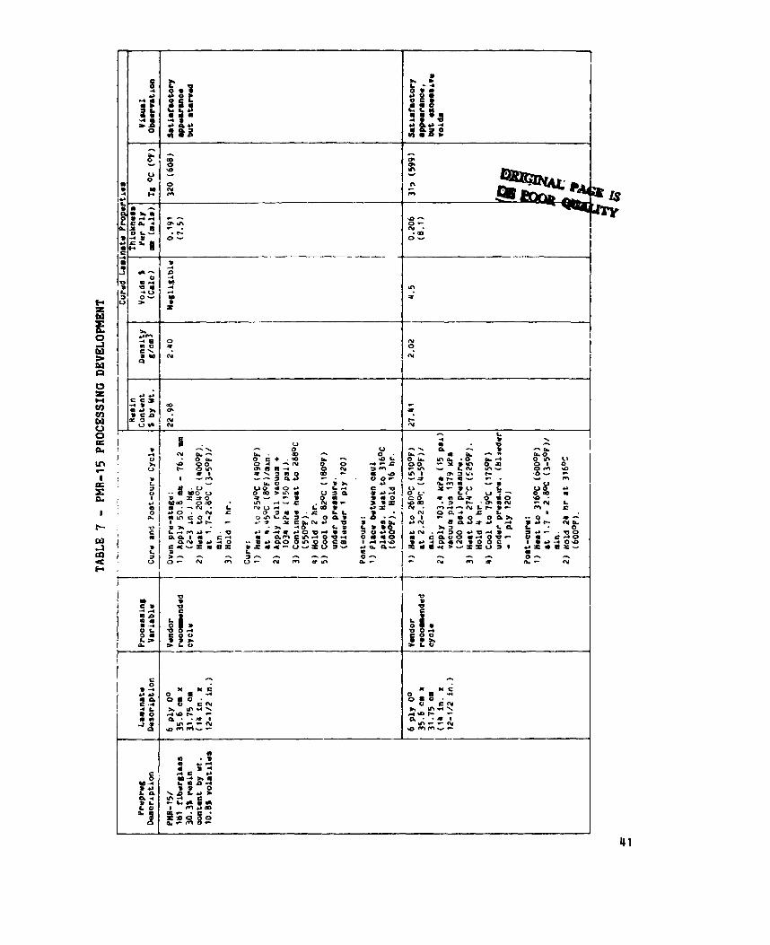
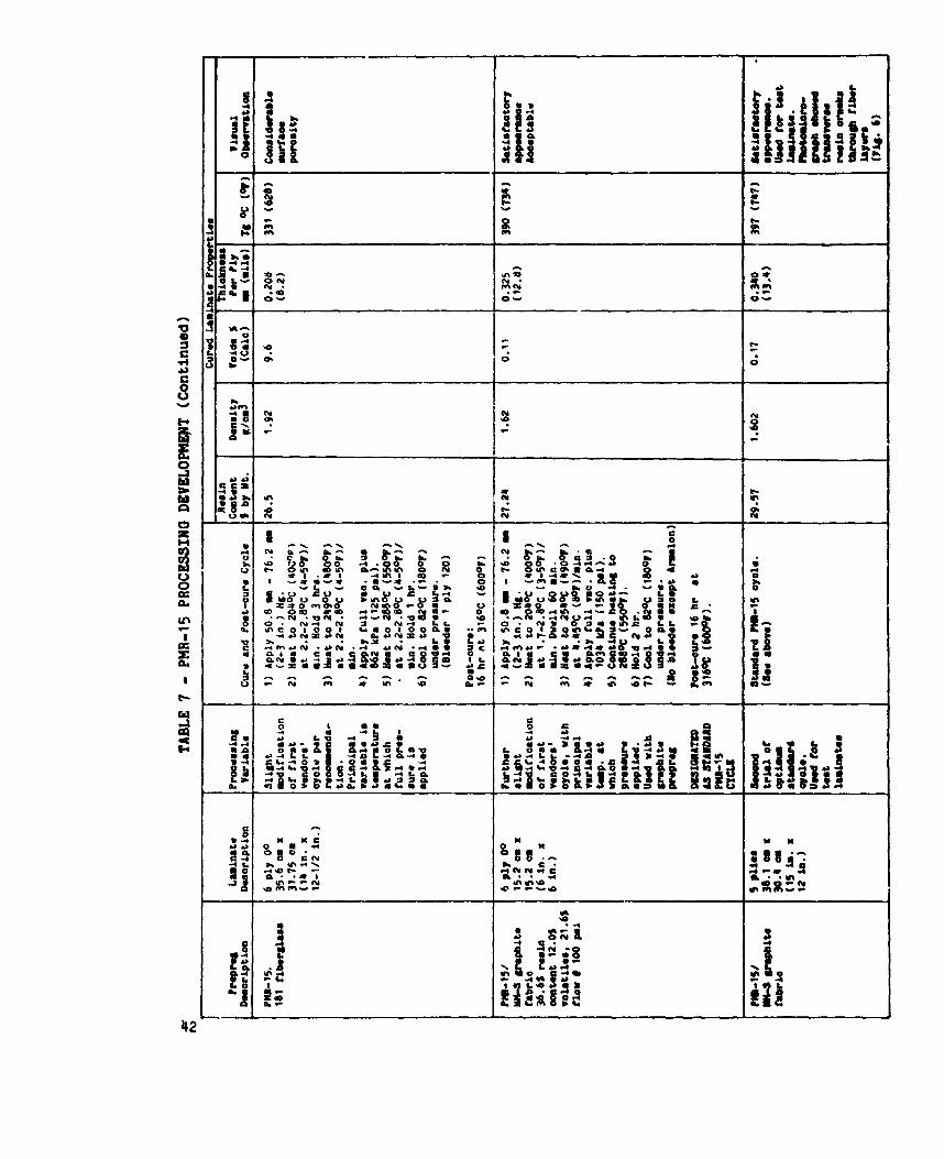
DM8-15 D r w dev- . - PMR-1S/fiberglass prepreg with recommended cure c y c l e s obta ined fiom the
l i t e r a t u r e . These processing t r i a l s are o u t l i n e d i n Table 7. These lamina tes appeared t o have excess ive v o i d s , and a modified c y c l e was used on the PMR-l5/graphite prepreg,
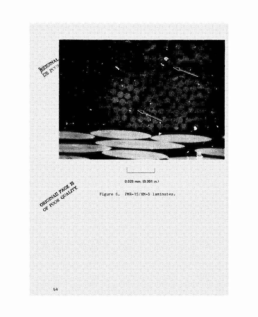
appeaFance, low voids , and acceptable r e s i n c o n t e n t . Photomicrographs revea led however, a r e g u l a r p a t t e r n o f t r a n s v e r s e cracks i n t h e r e s i n extending a c r o s s each fabric layer. (Fig. 6.) The cracks were n o t cont inuous across t h e lamina tes , and d i d n o t involve any f iber breakage. These cracks were thought t o be the r e s u l t o f thermal s t r e s s e a i n the r e s i n . PMR-15 is a r e l a t i v e l y b r i t t l e r e s i n , and undergoes very high process ing
The i n i t i a l t r i a l s on PHR-15 u t i l i z e d
T h i s provided a lamina te w i t h s a t i s f a c t o r y
15
temporatures with a maximum 343OC (65OOF) post-cure temperature. is a relatively brittre fiber with low strain-to-failure, and has a more highly negative thermal coefficient of expansion than other graphite fibers such as Thornel 300. PHR-15, showed the transverse cracks but only to a slight extent. also observed that a PHR-lS/HH-S laminate which had been imidieed at 204OC
(400oF) but not fully cured exhibited no cracks.
HX-S fiber
The NR-150B2 resin, which is much less brittle than It was
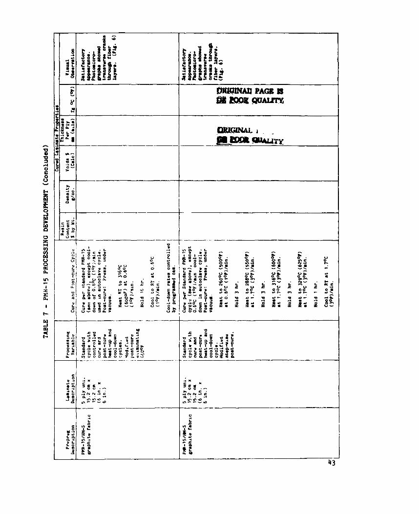
The approach taken to resolve this problem was to control cool-down rates, both in the autoclave cure and oven post-cure, to 0.56OC (l°F/minute) by means of cam controls. limit the maximum temperature to 316OC (60O0F) and to control heat-up rates. A stepped heat rise cycle was also used. successful in eliminating the transverse cracks, and it was finally concluded that this represented an inherent incompatibility with this particular resin-fiber combination. laminate fabrication and testing with this system in order to evaluate the honeycomb properties and obtain comparative data on the PHR-15 resin. summary of the PMR-15 skins and laminates is given in Table 8.
In addition, the post-cure cycle was modified to
None of these procedures was
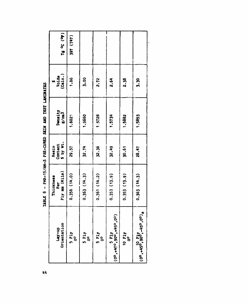
A decision was made to proceed with skin and test
A
Because of the less than optimum quality of the PMR-lS/graphite laminates, a decision was made to use PMR-lS/fiberglass skins for those panel specimens where skin quality could affect test results. purpose of these tests was to evaluate the graphite core prop-rties this approach was considered an acceptable means to ensure test failures in the core. Fiberglass skins were used for short-beam flexure, flatwise tensile, and plate shear tests; but graphite skins were retained for the flatwise compression specimens.
Since the primary
dev-. - An initial trial NR-l5082/fiberglasa laminate was fabricated using a Du Pont recommended cycle and appeared to be completely satisfactory. (See Table 9 for NR-150B2 processing trials.) The approach used in Task 2 processing of the NR-150 system differed from the Task ’ approach with NR-l50A2:82 in that autoclave cure temperatures were 16
held below the 316W (600oP) maximum autoclave temperature so that no heated platen was required. This was based on reoent Du Pont work indioating that the polymerization reaction of NR-150B2 uas essentially complete at 204OC (400°F), and that higher temperatures were required only for removal of the residual n-methyl pyrrolidone (N16) solvent and Condensation products (Ref. 4). This could be accomplished in an oven under vaouum or contact pressure. This is a more practical approach for eventual part fabrication, since supplemental heating for complex shaped parts would involve tooling costs approaching matched die tools. made to process the NR-150B2 under autoclave conditions without supplemental heaters.
Based on these considerations, a deci3ion was
The initial cure cycle successfully used on the NR-lSOB2Ifiberglass was tried on the NR-lSOW/HH-S graphite prepreg, and a poor q-iality laminate with high porosity was obtained. described in Table 9, were tried to eliminate voids, but these were not successful. r*eaources of the program, and a decision was made to fabricate and test the honeycomb panels in order to evaluate graphite core properties and obtain coltparative data. prepreg used in this Task used a mixture of 3 parts ethanol to 1 part NHP. Subsequent NR-150B2 development work in other NASA programs concluded that 100s Nt4P was a preferable solvent system (Ref. 5 ) . the ethanol contributes to the void problem by reacting with one of the NR-150 components in such a manner that processing characteristics are altered. NR-150B2 batch variables, as batch variability has been a recurring problem with this relatively new system. Another possibility is that residual PVA sizing, not fully removed from the HM-S fabric during cleaning, caused the void problee, although voids were not a problem with this same fabric combined with PMR-15. cure cycle variatians.
A large number of cure cycle variations,
Further trials and developments were finally beyond the
This decislon was influenced by the fact that the NR-15062
This work determined that
The inability to eliminate voids may also have been tf.9 results of
In any case, ths problem did not appear responsive to
17
A decision was made to use NR-l50B2/fiberglass skins for thocte honeycomb This was the same specimens where reaults could be affected by skin quality.
approach used with the PHR-15 panels described previously; and the decision was based on the same considerations: namely the nonoptlmua quality of the NR-150B2 graphite laminates, and the fact that the primary purpose of the test is evaluation of the honeycomb core and the LARC-13 adhesive rather than the laminates. tensile and plate shear tests; and graphite skins were used for the flatw+w compression specimens. A mutual agreement was reached with NASA to delete a set of NR-l5082/graphite laminates to be supplied to NASA for tests in view of the void content problems.
Fiberglass skins were used for short beam flexure, flatwise
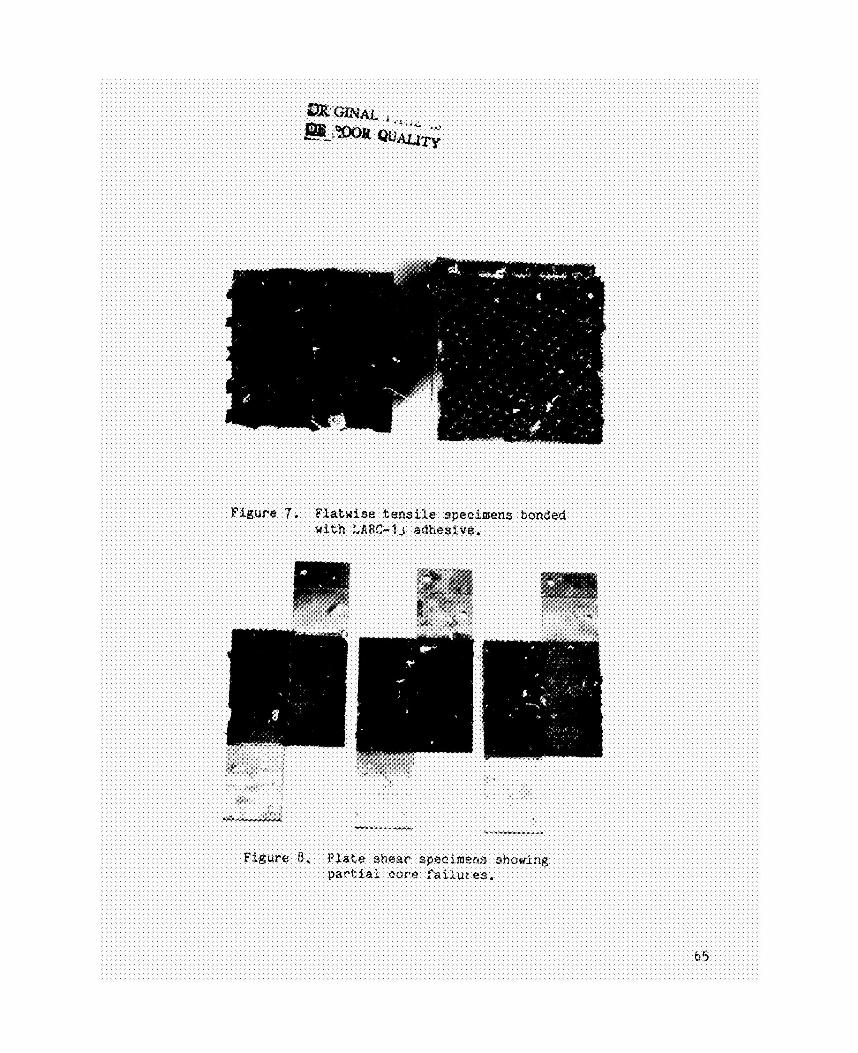
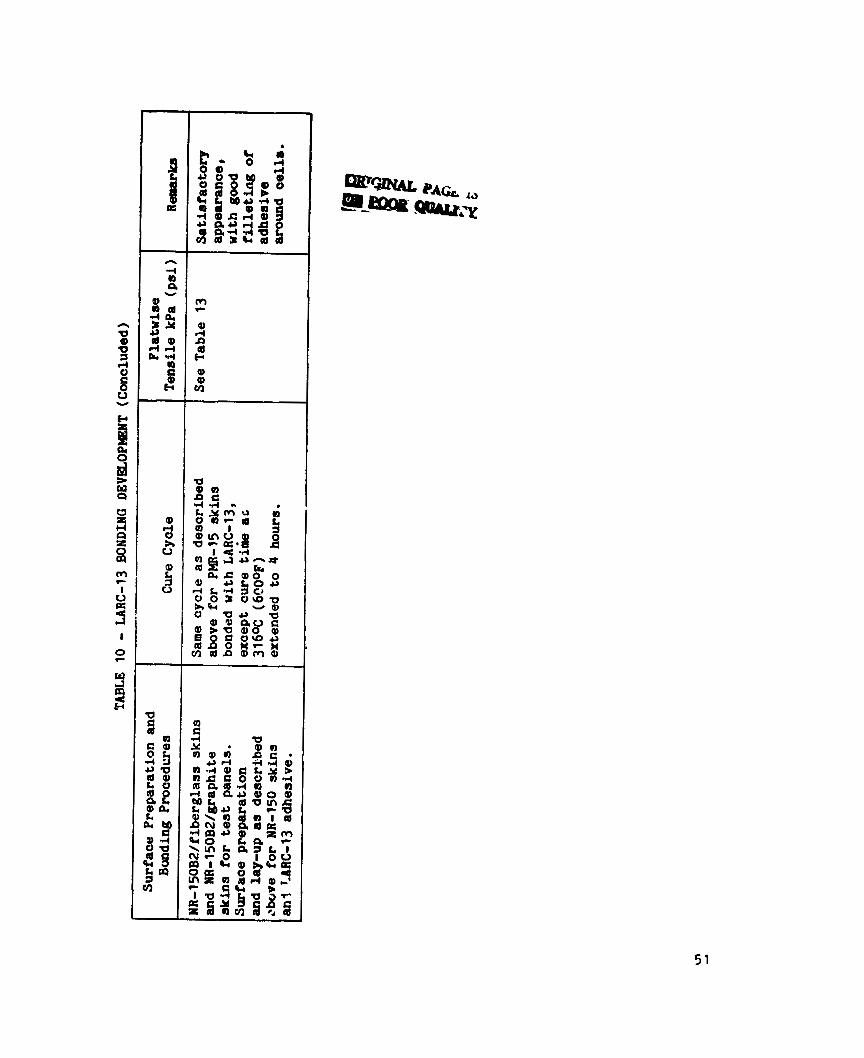
. - The cure cycles used in fabrication of the PHR-15/HH-S and NR-15OB2/HH-S test laminates and sandwich skins are indiaated in Tablea 7 and 9. C. trial sandwich panel was fabrioated with the LARC-13 as the skin-core adhesive, with pr-c?ured PMR-15 glass skins and a sample of fiberglass/polyimide core. The cure cycle and flatwise tensile results are given in Table 10 and a specimen after failure is shown in Figure 7. The results compare favorably with typical epoxy flatwise tensile results, so that e v w with the loading block failures, these results provided a confirmation of LARC-13's acceptability as a skin-core adhesive. The bonding cycle given in Table 10 was used for all test panel fabrication with the PMR-15 skins. The NR-15082 core as mentioned had a cell edge coating of unstaged NR-150B2 resin. NR-15OB2, with a modified cycle which is also shown in Table 10.
The LARC-13 proved to be compatible with the
This cycle, a compromise between recommended LARC-13 and NR-150B2 cycles, was used on two trial panels with NR-l50B2/fiberglass skins and the coated NR-lSOW/graphite core; one with LARC-13; and one with a cocured inner layer of NR- 150B2/f iberglass pre-preg ( Table 10) . satisfactory in both cases, but since the panels with LARC-13 showed less scatter it was decided to use LARC-13 on the NR-lSOB2/graphite honeycomb test panels. increased cure time could be used for the NR-150 panels.
The results were
A subsequent trial indicated the simpler PMR-15 bond cycle with
18
m. - Tests were conducted on the honeyoomb panels i n acaordance w i t h t h e test p lan o u t l i n e d i n TJble 2, and as d iscussed i n t h e Task 1 Approach. Some of the PHR-15 beam f l e x u r e speoilnans were run with an improper loading
arrangement (3.8 cm [1.5 in.] ino tead of 7.6 um 13 in.] between the t o p loading p o i n t s wi th the 15.2 cm [6 in.] span), but t h i s d i d no t a f f e o t u l t i m a t e strength r e s u l t s . URC-13 was used f o r plate and loading block bonds on specimens t o be tested at 288% (550OF). The s tandard LARC-13 c u r e c y c l e descr ibed i n Table 10 was used, and the LARC-13 proved s a t i s f a c t o r y f o r t h i s purpose with most failures a t 288% (55O0F) occur r ing i n the test panel. As mentioned, some NR-150A2:W 288% (550°F) plate shear and flatwise t e n s i l e specimens were rebonded wi th
LARC-13 and retested.
Otherwise no test problems were enaountered.
19
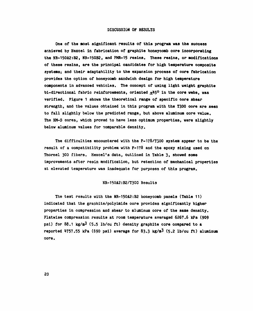
DISCUSSION OF RESULTS
One of the most significant results of this program was the success achieved by Hexcel in fabrication of graphite honeycomb core incorporating the NR-l50A2:B2, NR-150B2, and PMR-15 resins. These reains, or modifications of these resins, are the principal candidates for high temperature composite systems; and their adaptability to the expawion proceas of core fabrication provides the option of honeycomb sandwich design for high temperature components in advanced vehicles. The concept of using light weight graphite bi-directional fabric reinforcements, oriented d 5 O in the core weba, waa verified. strength, and the values obtained in this program with the T300 core are seen to fall slightly below the predicted range, but above aluminum core value. The HN-S cores, which proved to have less optimum properties, were slightly below aluminum values for comparable density.
Figure 1 shows the theoretical range of specific core shear
The difficulties encountered with the F-l78/T300 system appear to be the result of a compatibility problem with F-178 and the epoxy sizing used on Thornel 300 fibers. Hexcel's data, outlined in Table 3, showed some improvements after resin modification, but retention of mechanical properties at elevated temperature was inadequate for purposes of this program.
NR-l5OA2:B2/T300 Results
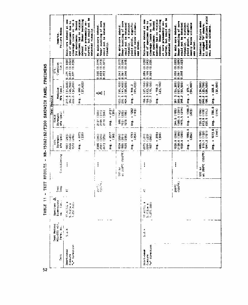
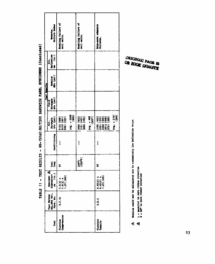
The test results with the NR-l50A2:B2 honeycomb panels (Table 11) indicated that the graphite/polyimide oore provides significantly higher properties in compression and shear to aluminum core of the same density. Flatwise compression results at room temperature averaged 6267.6 kPa (909 psi) for 88.1 kg/m3 (5.5 lb/cu ft) density graphite core oompared to a reported 4757.55 kPa (690 psi) average for 83.3 kg/m3 (5.2 lb/cu ft) aluminum core .
20
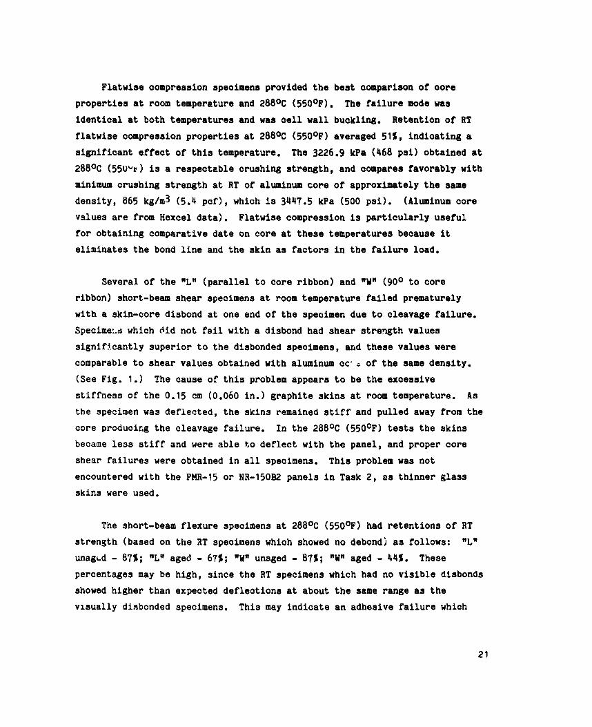
Flatwise compression specimens provided the best comparison of oore properties at room temperature and 288% (550°F). identical at both temperatures and was cell wall buckling. Retention of RT flatwise compression properties at 288OC (550°F) averaged 51%, indicating a significant effect of this temperature. The 3226.9 kPa (468 psi) obtained at 288% (55Wr) is a respecteble crushing strength, and compares favorably with minimum crushing strength at RT o f aluminum core of approximately the same density, 865 kg/m3 (5.4 pcf), which is 3447.5 W a (500 psi). values are from Hexcel data). for obtaining comparative date on core at these temperatures because it eliminates the bond line and the skin as factors in the failure load.
The failure mode was
(Aluminum core Flatwise compression is particularly useful
Several of the nLn (parallel to core ribbon) and (90° to core ribbon) short-beam shear specimens at room temperature failed prematurely with a skin-core disbond at one end of the specimen due to cleavage failure. Specime:.d which did not fail with a disbond had shear strength values significantly superior to the disbonded specimens, and these values were comparable to shear values obtained with aluminum cc' s of the same density. (See Fig. 1.1
stiffness of the 0.15 cm (0.060 in.) graphite skins at room temperature. the specimen was deflected, the skins remained stiff and pulled away from the core producing the cleavage failure. In the 288% (550°F) tests the skins became le39 stiff and were able to deflect with the panel, and proper core shear failures were obtained in all specimens. encountered with the PMR-15 or NR-150B2 panels in Task 2, E S thinner glass skins were used.
The cause of this problem appears to be the excessive As
This problem was not
The short-beam flexure specimens at 288OC (550°F) had retentions of RT strength (based on the 2T specimens which showed no debondj as follows: unagLd - 87%; "Ln aged - 67%; unaged - 87%; aged - 44%. These percentages may be high, since the RT specimens which had no visible disbonds showed higher than expected deflections at about the same range as the visually diabonded specimens.
nLn
This may indicate an adhesive failure which
21
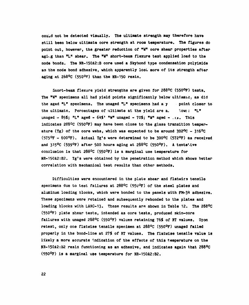
couid n o t be detected v i s u a l l y . s t i l l been below u l t i m a t e core strength a t room temperature. The f i g u r e s do
p o i n t o u t , however, the greater reduct ion of "W" c o r e shear properties after agit.g than "LW shear. node bonds. The NR-150A2:B core used a Skybond t y p e condensation polyimide as the node bond adhesive, which apparent ly los i more of its atrength after aging a t 2b80C (550OP) than the NR-150 r e s i n .
The u l t i m a t e s t r e n g t h may therefore have
The "WW ahort-beam f l e x u r e test a p p l i e d load t o t h e
Snort-beam f l e x u r e y i e l d strerqths are g iven for 288OC (5509) tests. The nWa specimens a l l had y i e l d p o i n t s s i g n i f i c a n t l y below ultf.inato, as d i d
the aged "LN specimens. The unaged "L" specimens had a y , p o i n t closer to the u l t imate . Percentages of u l t i m a t e a t t h e y i e l d are a. tow: : "L" unaged - 85%; "L" aged - 64S1 "Wn unaged - 70%; "Wn aged - , I # . This
i n d i c a t e s 288OC (550°F) may have been c l o s e t o t h e glass t r a n s i t i o n temper- a t u r e (Tg) of t h e core webs, which was expected t o be around 302% - 316% (575OF - 6000F). Actual Tgls were determined t o be 3OO0C (572OP) as rece ived and 315OC (599OF) after 500 hours aging a t 288OC (550°F). conclusion is t h a t 288OC (55O0F) is a marginal use temperature f o r NR-l50A2:B2. c o r r e l a t i o n wi th mechanical test r e s u l t s than o t h e r methods.
A t e n t a t i v e
Tg's were obta ined by t h e p e n e t r a t i o n method which shows better
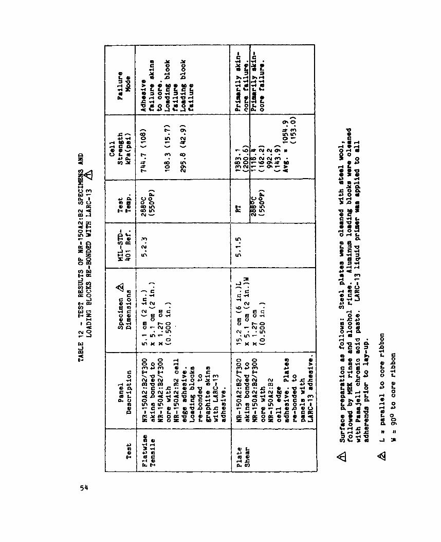
D i f f i c u l t i e s were encountered in t h e p l a t e shear and flatwirs t e n s i l e specimens due t o test f a i l u r e s a t 288OC (55U0F) of the steel plates and aluminum loading blocks, which were bonded t o t h e panels w i t h FM-34 adhesive. These specimens were r e t a i n e d and subsequent ly rebonded t o the plates and loading blocks w i t h LARC-13. These r e s u l t s arc! shown i n Table 12. The 288% (550°F) plate shear tests, intended as c o r e tests, produced skin-core f a i l u r e s w i t h unaged 288OC (550OF) values r e t a i n i n g 76% o f RT values . retest, only one flatwise t e n s i l e specimen a t 288OC (550°F) unaged failed
proper ly i n t h e bond-line a t 27% of RT values . l i k e l y a more a c c u r a t e 4.ndication of t h e effects of t h i s temperature on the
NR-l50A2:B2 r e s i n func t ioning as a n adhesive, and i n d i c a t e s a g a i n t h a t 288% (550°F) is a marginal u8e temperature f o r NR-l50A2:B2.
Upon
The flatwise t e n s i l e v a l u e is
22
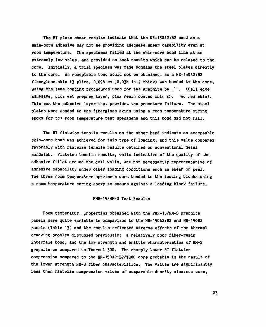
The RT plate shear r e s u l t s i n d i c a t e t h a t t he NR-l50A2:B2 used as a skin-core adhesive may n o t be providing adequate shear c a p a b i l i t y even a t room temperature. extremely low v d u e , and provided no test r e s u l t s which can be related t o t h e
core. I n i t i a l l y , a t r i a l specimen was made bonding t h e steel plates d i r e c t l y t o the core. fiberglass s k i n ( 3 plies, 0.096 cm c0.038 in.; t h i c k ) was bonded t o t h e core, us ing t h e same bonding procedures used for t h e gra3hice pa ---. adhesive, p l u s wet prepreg layer, p l u s r e s i n coa ted ontc t:.c .er ' : ea s k i n ) . This was t h e adhesive l a y e r t h a t provided t h e premature f a i l u r e . plates were oonded t o t h e fiberglass s k i n s us ing a room temperature c u r i n g epoxy f o r tl- room temperature t es t specimens and t h i s bond d i d n o t fa i l .
The specimens failed a t t h e skin-core bond l i n e a t a n
An ecceptab le bond could n o t be obta ined , so a NR-l50A2:B2
!Cell edge
The steel
The RT flatwise t e n s i l e r e s u l t s on t h e o t h e r hand i n d i c a t e an acceptable skin-core bond was achieved for t h i s t y p e o f loading , and t h i s v a l u e compares favorably w i t h flatwise t e n s i l e r e s u l t s obtained on convent ional metal sandwich. adhesive f i l l e t around the cell walls, are n o t n e c e s s a r i l y r e p r e s e n t a t i v e of adhesive c a p a b i l i t y under o t h e r loading c o n d i t i o n s such as shear or peel. The three room temperatiire specilllens ware bonded t o t h e boading blocks us ing a room temperature c u r j n g epoxy t o ensure a g a i n s t a loading block f a i l u r e .
Flatwise t e n s i l e r e s u l t s , whi le i n d i c a t i v e of t h e q u a l i t y of ihe
PMR-15/HM-S Test R e s u l t s
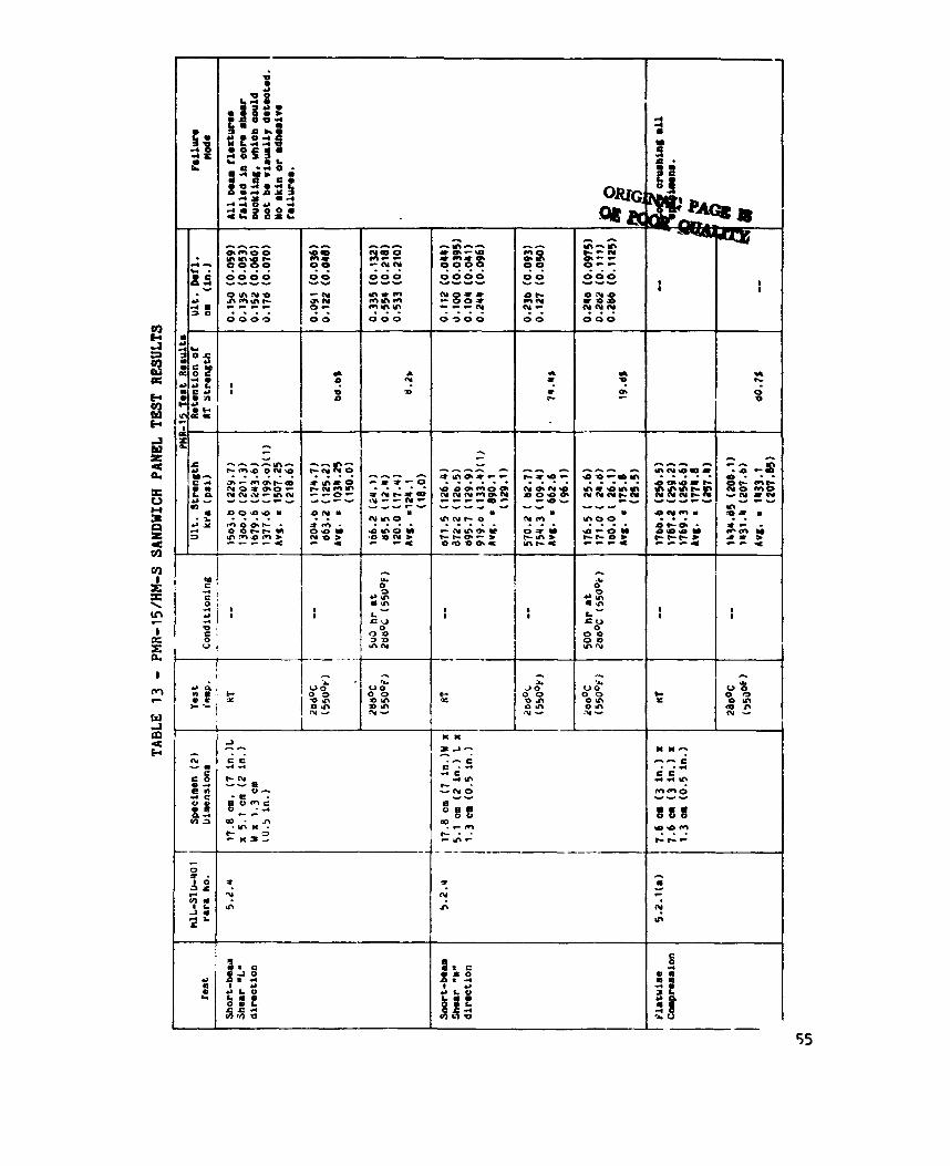
Room temperatur, groperties obtained wi th t h e PMR-15/HH-S graphi te
pane ls were q u i t e v a r i a b l e i n comparison t o t h e NR-l50A2:B2 and NR-150B2 panels (Table 13) and t h e r e s u l t s reflected adverse effects o f t he thermal cracking problem discussed previously: i n t e r f a c e bond, and the low s t r e n g t h and b r i t t l e characteristics of HM-S graphite as compared t o Thornel 300.
compression compared t o t h e NR-l50A2:B2/T300 core probably is t h e r e s u l t of t h e lower s t r e n g t h HM-S fiber characteristics. less t h a n flatwise compression va lues of comparable d e n s i t y aluminum c o r e ,
a r e l a t i v e l y poor f i b e r - r e s i n
The s h a r p l y lower RT flatwise
The va lues are s i g n i f i c a n t l y
23
and panels with HItS core could be marginal or inadequate under impaut and
crushing loads. The PHR015/graphite core shear s t rength in the .La di rec t ion at RT, however, compared r m t l p well t o t h e other graphite oores and t o comparable d e n s i t y a l u i n u m core. The RT lower than t h e other cores which may reflect a poorer q u a l i t y node bond.
co?e shear v a l u e s are somewhat
Short-beam f l e x u r e and flatwise compression v a l u e s tested at 288%
(550q) without heat aging r e t a i n e d an acceptable percent of RT values (68.6% r e t e n t i o n in *La short-beam flexure, 74.4% r e t e n t i o n in rUr short-beam
flex1 'e, hnd 80.7% r e t e n t i o n i n flatvise campression). A drastic drop-off
ocours in these properties when tested at 288% (550*) aft- 500 hours
at 288% (550°F) with r e t e n t i o n s of only 8.2% and 19.8% in "La and short-beam shear respec t ive ly . (550q) disbonded during handling and could not be tested. These r e s u l t s s t rongly i n d i c a t e t h a t 288% (55OoC) is beyond t h e capabilities of PHit-15 r e s i n except for very short-term a p p l i c a t i o n s .
The flatwise t e n s i l e specieens aged at 288%
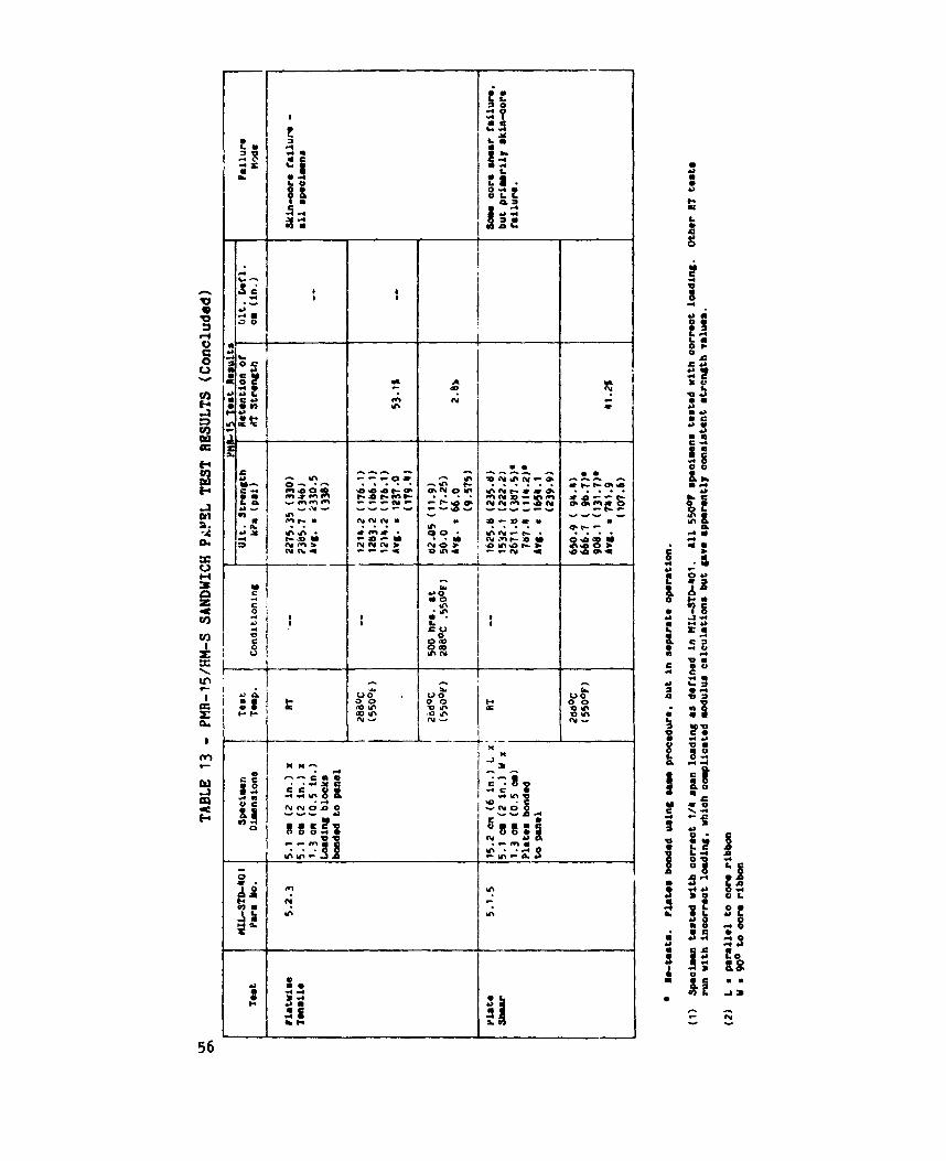
Platwise t e n s i l e r e s u l t s on t h e PMR-15 panels reflect the behavior of t h e LARC-13 ~ d h e s i v e and w i l l be d iscussed i n t ha t sec t ion .
UodulUS v a l u e s were c a l c u l a t e d from t h e short-beam flexure data us ing HIL-STD-401 formulas but no reasonable v a l u e s could be obtained. Core modulus de te rmina t ions from sandwicn bea6 f l e x u r e are extremely s e n s i t i v e t o s l i g h t errors i n s t r a i n measurement, and p l a t e shear is g e n e r a l l y recommended for core shear modulus determination. Unfortunately, Lockheed d id n o t have a proper extensometer set-up fa r plate shear s t r c i n measursments and development of t h i s capabi1it.y was beyond t h e scope of t he program.
only p l a t e shear strength was obtained, and t h e core shear s t r e n g t h s obta ined were somewhat lower than obtained i n beam f l e x u r e . T h i s reduct ion is probably caused by t h e partial skin-oore disbond mted i n t h e failed
specimens.
Thus,
24
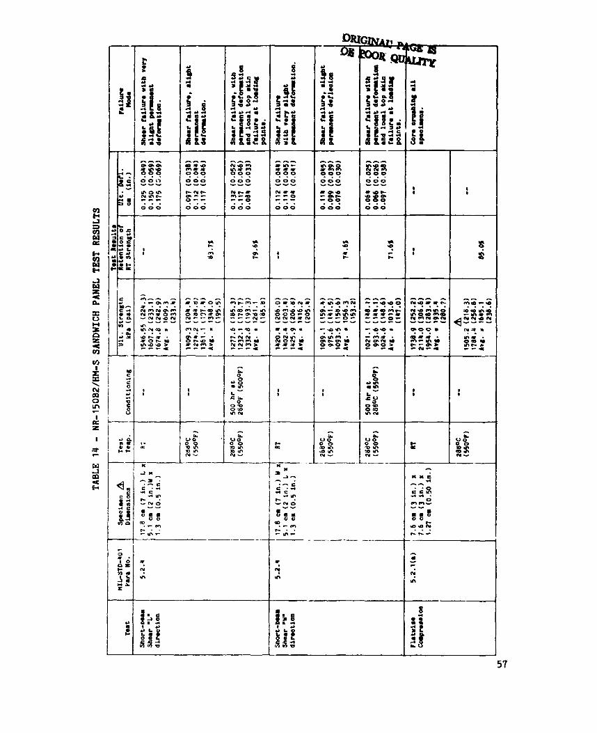
NR-15082/!iN-S Test Results
The NR-lSOB2/HH-S core had coaparable room temperature beam flexure and flatwise aomprsssion properties as the M-15/HH-S core. NR-lSOB2 test results.) "La beam flexure and by plate shear was somewhat lower than the NH-l5OA2:82/T300 aore and caparable density aluminum aore, refloating the lower strength aharaateristics of the HH-S fiber. like the PIIA-lS/HH-S core, had RT flatwise ampression values sl@ifioantly less than the NR-l50A2:BZ/T300 aore and aluminum core of aompar8ble density. As previously disaussed, these low values are attributed to the low strength brittle characteristias of HH-S graphite as colapared to Thornel 300, 8nd would indicate a serious structural limitation for graphite oore made with this fiber. (Ref. Table 14)
(See T8ble 14 for The ultimte RT aore shear strength as determined by
The NR-150B2/Hn-S aore
Reterition of short-beam flexure and flatwise compression properties at 288% (550oF) without aging was comparable or slightly superior to the PNR-15
core and the NR-150A2:W cores (841, 75'11, and 85% for 'La beam flexure, "W" beam flexure, and flatuise compression respectively). The NR-150A2:W core had less retention of flatwise compression at 288% (55OoF) than the other two cores but the absolute 288% (550°F) flatwise compression value of the NH-150A2:BZ aore was still substantially higher than 288% (550°F) flatwise compression of th3 core3 incorporating HH-S fiber.
After 500 hours aging at 288% (550°F), the NR-150B2 aore had exaellent retention of RT properties (80s and 721 for "Ln and OW" ShOrt-be8la shew respeatively) , aomparable to 288OC (550OF) retentions of the aged NR9150A2:B2/T300 core and greatly superior to 288% (550°F) retention of the aged PWR-15 core. Considering the indiaations that the NR-?SOB~/H!J~-S system used may have been less than optimum with batch variability problems and poor resin-fiber interface, these results are strong indications that the NR-150B2 system has excellent aharacteristics for long-term 288OC (550OF) servlae.
25
Flatwise tensile results are dependent on charactteristics of the LARC-13 polyimide adhesive, and are discussed in the next section.
The trial panels bonded with the LARC-13 film adhesive at 9.29 kgh2 [0.06 lb/sq ft], supported on 112 glass scrim, gave acceptable f?.atwise tensile test results which compared favorably with typical epoxy flatwise tensile values (Table 10). When the LARC-13 was used to bond skins on the NR-150B2 core coated with an unstaged cell edge layer of NR-15082 resin, increased flatwise tensile value were obtained (2899.3 kPa l420.5 psi] vs.
1999.55 U a 1290 psi]) for values on uncoated PHR-15 core. This demonstrated that LARC-13 could be effectively cocured with NR-150B-2.
LARC-13 was also used to rebond aluminum loading blocks and steel plates onto NR-150A2:U flatwise tensile and plate shear specimens which had failed at 288OC (550°F) in the loading blocks and plates. with FM-34 condensation polyimide adhesive. occurred on two out of three 288% (550°F) flatwise tensiles (Table 121, but the plate shear-tests at 288% (550°F) all failed in the specimen (Fig. 8). These specimens indicated that LARC-13 may be adequate but somewhat marginal for short-term 288OC (550°F) exposures.
These had been bonded Loading block failures still
The flatwise tensile results obtained on the PMR-15 and NR-150E32 honeycomb panel specimens (Tables 13 and 14) showed excellent adhesion at room temperature. drastically in strength with two loading block failures out of the three specimens. However, the PMR-15 flatwise tensiles, with LARC-13 bonded loading blocks, retained a reasonably good 53% of RT values. A common difficulty with flatwise tensile testing is inadvertent introduction of eccentric loads which produce peel failures on the specimen. This may account for the failures of LARC-13 aluminum loading block bond at 288OC (550°F) on one set of
A t 288OC (550°F) the unaged NR-150B2 specimens fell off
(Loading blocks were also bonded to the specimens with LARC-13).
26
spuimens but not the other.
at 5 5 0 9 . disbonded during handling and the PIQI-15 8pouimen8 retained le88 than 32 of
LARC-13 obviously is l8aldng i n :eel s tren8th
After 500 hours wing at 288% (55OoF), the NR-15OBt spinen8
RT V 8 1 U O 8 , indiaat ing LARC-13 ha8 DO c r a p b i l i t y 8t 288OC (550oF).
In sumary, LARC-13 appear8 to have eraelleat adhesion ohwauteristios for skin-aore bondly: , but 288% (550*) is beyond its umful temperature m e , excrept for short-term appliuationa.
27

CONCLUSIONS
The demonstration by Hexcel of the feasibility of produoing hon:joLaL core with light weight graphite fabrics and polyimide resins waa the most significant result of this propam. This product is now an available structural material for high temperature applications with two of the most promising poiyimide systems, NR-150B2 and PHR-15 as matrix materials. The core shear teat results also confirmed Hexcel's predictions; and verified that graphite honeycomb core, with continuous Giber reinforcements oriented ~ 4 5 ~ to the web, provides specific shear properties comparable or superior to metallic honeycomb. metal cores in shear properties, and graphite core can be used with composite skins in structural applications where metallic core would create serious corrosion and thermal mismatch problems.
This is the first nonmetallic honeycomb to approach
Of the three polyinide systems evaluated in the progran, PHR-15 appears to be margirial for short-term 288% (550°F) use, and is not acceptable for long-term 288% (550°F) applications. NA-150B2 appears to have excellent 288OC (550°F) capabilities, while the NR-150A2:W is acceptable for 288% (55OOF) but has less thermal stability than the NR-150B2.
s
The e;r>xy sized Thornel 300 fibers reinforcements used in the first task appear to be acceptable for high temperature applications when combined with suitable polyimide resins, despite the compatibility problems encountered with F-178. Neither the fiber or the s iz ipq appeared to adversely affect elevc,ted temperature properties with the NR-l50A2:B2 system.
The higher modulus HM-S fibers also appear to have acceptable thermal stability combined with the PMR-15 and NR-150B2 systems. Thornel 300 fibers provided core shear properties slightly less but reasotably close to predicted values. compression values of the HM-S graphite core indicates that high modulus graphites would not provide sufficient crushing strength to the panel to be
Both HM-S and
However the sharply reduced flatwise
28
practioal for structural u8e. fibers, despite theoretioally lower thermal stability, appear to be the best seleotion for graphite core reinforcement.
Thornel 300 and similar intermediate modulus
Problems enoountered with skin laminate quality of PHR-lS/HEI-S indicate that thermal mismatch is a factor that needs to be carefully oonsidered in combining a brittle, high temperature curing polyimide with high modulus graphites. bility and/or storitge stability problems. related to the use of ethanol in the solvent mixture, which has now been discontinued.
The problems with the NR-150B2 are indicative of batch varia- These problems may have been
This program represented one of the first use8 of woven high modulus Hx-S fibers. be a promising product. contributed to the problems with the cured laminates, and application and removal of sizing is an area requiring further studies with these new fabrics.
Despite heat cleaning and weaving difficulties thi8 appears to There is a possibility that residual PVA sizing
LARC-13 polyimide adhesive appears to provide satisfactory adhesive characteristics, with excellent processing characteristics, and the system appears well adapted for skin-honeycomb core bonding, and for cocuring with other polyimide systems. temperature, however, even for short-term applications.
288% (550°F) appears to be a marginal use
29
REFERENCES
1. Gibbs, Hugh H.: Latest DeVelOpm3nt8 in NR-150 Polyimide Binders. Paper presented a t 19th Nat ional SMPE Symposium, 1974.
2. S e r a f i n i , T. T. and Vanucci, R. D.: Tailor Making High Performance Graphi te Fiber Reinforced PHR Polyimides. NASA THX-71616, 1375.
3. NcHahon, Paul E.: Oxidat ive Res is tance of Carbon F i b e r s and Thei r Composites , Celanese Research Co . , 1977.
4. Cibbs, Hugh H.: S t a t u s Report NR-150 Polyimide Binders and Adhesives. Paper presented at 21st Nat ional SAl4PE Symposium, Apri l 1976.
5. Develop and Denonstrate Manufacturing Processes for Fabricating Graphi te Filament Relnforced Polyimide (Gr/PI) Composite S t r u c t u r a l Elements. Q u a r t e r l y Report No. 1 , March 8 - June 8, 1977, CASD-NAS-776-318-1, General Dynamics, Convair Div.
I I
32
I
n R Q, e, m P
I
33
X I
i
i' - -
@ + a "46
._ .
T-
x l x
I
c. 9'; 3s * m
:
34
n c
d CI
c
m E
Q
a
? gr c Y
0 I
Y
35
36
I * I I , " . I i o n v 1 5 ; I
r - I k C k
!--- I
i
ii a n
I
I I
t
I
I I
I
I
9
m c
I
Y r
VI I -QO P m c m
B CB 37
I I i
. - - ' 0 - ' a-
t -
C ' 6
i I
I I I I , i
I
:: r- * c
c P ii
I
- S ? m m a- ..-
- 4)
M.o
.o 0 -
r'?
39
40
s 4
4
CD 4 4
Y
t
n
4)
o( N 0:
s > - - - 0.- 01 m
L
0 - a,*
? t
0
41
* 4
L. V
:
a i: U
a. V
I)
a
42 I
c c
0 t 0
? c
L c 0 0 -4
0 r
L c m b L( e
-
0
(r? 3
-
0 ro cn r
f + cu rn
- n m
P Y
m ro m 0
-
h 4 & O
0 In
n 0 0
0 In t +
h - 4 0 & O
OI m -
t +
L
e, % ..
U -
c
r
L L-
f f 5
& $ E g g Q
(Y ( Y m a
45
x rn = r
I
i - 1: m
- -A-
I
I I
..- ou
I 1 47
I I
"1 t c
"1 1
ro m m s r
m c t- = c
9
0, N ? ji
48
I-I .-
49

m P a, 0;
i Q h 3 u
I
a
5 1
I I ZS", , 9 9 9
010101 - 0 - 9'9 0 0 0 I O 0 0 I
a!
- Y > a
r)r - 9 0 c o tu-
I I 1
i , Z m
t . i F
i
t - -
52
P 5 + + aJ rt
I 8
I
c. 0
- . -
I
I
a
00' 0 0 mu3 (Yn (Y-
o c 9 cn
i
? ? n
a 0 r(
53
a t 0
4
a a
I
c5
O!?
I n
.m iw m
ln .- In
Q Q Y
C 0 P D rl h 0 L. 0 0
0 c, P 4 0 rt rt Q
i H
4
n n 4 t
t 0 V
0 c,
00 6
II
3
54
i a
ne-- - m o o *mor- 0 0 0 0 ???? Y C Y Y
00 1555 Y Y
0000 Y Y Y I 252 I I I (YO** L O O * c r r ( v
0 9 0 0 . . . .
o+ y 0 0 I
-I- * t
t 4- 4 I h
3 1 8
1 I
I I
I 8
-- ----t----- 4
i. 2 0 0 0
0 - .v - o n
Y O n e f .II c .I I- 3:
55
2 m m
1 !
I I
6 1
N - Q *
I
L
0 9 0
z"N I I I
l m
"I m 1:" In
DR
en- =** m * *
0 0 0 9 9 9
:!!!: 9 : : 0 0 0
0 0 0 w - 1
n '9 c +
'9 f t-
1 1
I I 1
t t m u . . . 499 o ( Y V I - ( Y o r u m rrr:
I I
I I
I I 1
c E 1. a
.- E c * 4 4 c
-(Yo
u a m v u aD . - m I C . . -In-
+-.I4 mu-
.- - __-_____
s ?
57
I x w i m
i I I i
I i I
i c. I a
NR 150A2.BZITJ00 CORE
NR lSOB2IMM-SCORE
1 1 1 1 1 I 32 (2) u) 13) 6# 14) 80 (51 % (6J 112 (7) 128 :'
CORE DENSITV . k0/m3 ( I M t 3 I
Figure 1 . Graphite honsvcolnb core shear strength ( A T ) .
59
0 HEXCCLTEST VALUES
11, I I I i 1 I 32 (2) 40 (31 g4 14) 80 (51 96 (6) 112 (71 1211 (81
CORE DENSITY . k9/m3 (lblh3)
"L" = Pa d e l to cnn ribbon dimtion
Figure 2. Graphite honeyoomb oore shear modulus (17T).
60