development & building control - land transport authority · pdf filepermission of the...
TRANSCRIPT

Development & Building Control

Street Works Proposals Relating to Development Works
Jan 2007 Edition
All rights reserved. No part of this publication may be reproduced, stored in a retrieval system, or transmitted, in any form or by any means, electronic, mechanical, photocopying, recording or otherwise, without the prior permission of the Development & Building Control Division, Land Transport Authority.

Street Works Proposals Relating to Development Works
PREFACE
This publication explains the procedures of submitting street works proposal plans to
the Land Transport Authority for clearances. It also introduces the technical
requirements, standards and specifications of the Land Transport Authority to aid the
design of development layout with regards to proposed street works, as well as the
engineering design and construction of proposed street works. Although it touches
more on the civil engineering design and construction of street and street related
works, this publication has also highlighted some of the essential submission
procedures and technical requirements in relation to the design and installation of
Mechanical and Electrical items to street and street related works.
This publication also highlights the essential submission procedures and technical
requirements in relation to the design and installation of Mechanical and Electrical
works for covered linkway, underpass and pedestrian overhead bridge, as well as
street lighting for private streets constructed under Section 18 of the Street Works
Act.

Street Works Proposals Relating to Development Works
STREET WORKS PROPOSALS RELATING TO DEVELOPMENT WORKS Contents Definitions Part I - Submission Procedure Chapter 1 Submission of Development Proposal Plan for Development
Control (DC) Clearance Chapter 2 Submission of Building Plans and Street Plans Chapter 3 Development Control (DC) Clearance for Development Proposal
within Road Structure Safety Zone Chapter 4 Inspection and Handing Over of Completed Street Works Part II - Specifications and Requirements Chapter 5 Entrance access arrangements Chapter 6 New Street Proposals Chapter 7 Street Plan Presentation Standard and Requirement Chapter 8 Safeguarding of Road Reserve Lines Chapter 9 Traffic Impact Assessment Chapter 10 Requirements on Engineering Works within Road Structure
Safety Zone Chapter 11 Engineering works within SURS Tunnel Protection Reserve Chapter 12 Excavation works adjacent to Road Reserve Chapter 13 Application for Temporary Crossings Chapter 14 Road Testing

Street Works Proposals Relating to Development Works
Appendices
1-A General Requirements To Comply With During Development Plan Submission
2-A General Requirements To Comply With During Street Plan Submission
2-B Application Form under Section 20(1)
2-C Checklist for street lighting design submission
4-A Certificate of Supervision
6-A Sample of banker's guarantee
6-B Sample of Order
6-C Sample for reduced BG amount
8-A Cross-section of major roads
8-B Cross-section of industrial roads
8-C Cross-section of residential roads (public housing)
8-D Cross-section of residential roads (private housing)
8-E Cross-section of service roads
8-F Various Types of cul-de-sacs for industrial roads
8-G Various types of cul-de-sacs for non-industrial roads
8-H 18.0m road reserve at junction
8-I 26.2m road reserve at cross-junction (with slip roads)
8-J 26.2m road reserve at cross-junction (without slip roads)
8-K 31.8m road reserve at cross-junction (with slip roads)
8-L 38.6m road reserve at cross-junction (with slip roads)
9-A Key Issues to be addressed in a TIA Report

Street Works Proposals Relating to Development Works
DEFINITIONS
In this publication, unless the context otherwise requires: Authority : means the Land Transport Authority (LTA) of
Singapore established under the Land Transport Authority of Singapore Act 1995;
Commuter Facility : includes covered or opened linkways, pedestrian
overhead bridges, underpasses and footway; Development : has the same meaning as in the Planning Act (Cap
232); Engineering Works : refers to construction works or activities such as
excavation for basements and other building structures under land; installation of foundation piles, sheet piles, bore holes, wells, ground anchors and tie back; and the operation of cranes, hoist or heavy equipment.
New Street : includes:
• the continuation of an existing street; • the widening or alteration of any existing street;
and • the adapting of a street made for foot traffic only
and for carriage traffic; Public Street : has the same meaning as in the Street Works Act Private Street : means any street not being a public street; Professional Engineer : means a person registered under the Professional
Engineers Act; Qualified Person (QP) : means a person as defined in the Building Control
Act (Cap 29); Road Related Facility : includes any traffic sign, directional sign, street name sign, traffic light, bus shelter, railing and any other
road related structure and facility within the street maintained by the Authority;

Street Works Proposals Relating to Development Works
Road Structure : includes any bridge, underpass, road tunnel, earth retaining wall & ancillary buildings – such as substations and pump house serving road tunnels, control centres for road tunnel operation;
Road Structure Safety Zone : means that part of the land or area which is 20m
from the outer most edge of any part of a road structure;
Street : includes:
• any road, bridge, underpass, tunnel, footway or
passage, whether thoroughfare or not, over which the public has a right of way; and
• all channels, drains, ditches and reserves that are
deemed to be part of a street; Street Plan : means the plan relating to the construction of a new
street as referred to in section 18 of the SWA; Street Works : means works of levelling, paving, metalling,
flagging, kerbing, channelling, draining, lighting, laying of cables and mains and other utility services and otherwise the making good of a street or part of the street;
SWA : means the "Street Works Act (Chapter 320A)".

Street Works Proposal Relating to Development Works
CHAPTER 1 SUBMISSION OF DEVELOPMENT PROPOSAL PLAN FOR DEVELOPMENT CONTROL (DC) CLEARANCE 1.1 Introduction
The Qualified Person (QP) has to obtain LTA's clearance at Development Control (DC) stage when the development proposals involve the following but not limited to: a) Construction of new street as defined in the Street Works Act. b) Alteration of an existing street including relocation/widening of
existing access point(s) to the development. c) Alteration of an existing street including street furniture and
traffic marking/traffic signs within the road reserve. d) Construction of new access point(s) to the development. e) Construction of road within the road widening plot set aside
from the development. f) Development proposal that is affected by the line of road and
tunnel reserve. g) Development that is located within the road structure safety
zone. h) Developments that involve basement works.
1.2 Key Areas to Evaluation for DC Clearance
The following areas are evaluated based on prevailing standards and when LTA processes the submission of plans by the QP: a) suitability of the access points b) adequacy of a new road proposed c) extent of frontage improvement d) whether a Traffic Impact Assessment (TIA) is required e) adequacy of commuter facilities such as pedestrian overhead
bridges, bus stops or bus-bays, taxi stands, etc.

Street Works Proposal Relating to Development Works
f) improvement needed to the current traffic scheme g) relocation of any street lights h) endorsement of LTA’s general requirements as shown in Appendix
1-A.
1.3 Additional information
LTA would also evaluate whether a proposed development may affect an existing road or road structure to safeguard the interest of the general public while the development is undergoing construction. Additional information would be requested if a development is - a) within the proximity of road structures b) affected by the road tunnel protection reserve
c) involves excavation adjacent to the road reserve
The foregoing chapters describe in detail the additional information that LTA requires. Where necessary, LTA may request for a topographical survey plan and / or some photographs of the site to evaluate the proposal.
1.4 Submission of Building Plan no longer required
Since December 2004, LTA has streamlined the approval process for Street Works. We no longer require QP to submit the building layout plan during the BP approval stage. This includes commercial development, educational institutions (Universities and Polytechnics) and new street proposals. However, QPs will need to incorporate all requirements of LTA, previously indicated in the building layout plan, in the DC layout plan for LTA’s clearance.
1.5 Follow-up submission after obtaining DC clearance
Once the DC clearance for the proposed development layout is obtained, the QP (Civil) shall submit the Street Plan to obtain BP clearance. The street plan shall base on the approved DC layout plan. The street plan shall also be prepared basing on all prevailing specification, standards and guidelines.

Street Works Proposal Relating to Development Works
CHAPTER 2 SUBMISSION OF STREET PLANS 2.1 Introduction
At Building Plan approval stage, while all building layout plans must be submitted to Building and Construction Authority (BCA) for approval, LTA only requires the QP (Civil) to submit Street Plans.
2.2 Proposed Street Plans Submission In preparing Street Plans, the QP (Civil) shall make reference to the relevant chapters in the following publications and comply with the requirements stated therein: a) Street Works Act (Chapter 320A) & Street Works (Private
Street Works) Regulations b) Civil Design Criteria for Road & Rail Transit Systems c) Architectural Design Criteria for Road & Rail Transit Systems d) LTA Standard Details of Road Elements e) Materials & Workmanship Specification for Civil & Structural
Works f) Materials & Workmanship Specification for Architectural
Works Sections b) to f) can be obtained from LTA’s website at the following url: http://www.lta.gov.sg/index.html. Whenever there are any changes to guidelines or procedures, LTA would issue a circular to professional bodies. A copy of the circular would also be posted in the Corenet e-Info for easy reference.
2.3 Submission Requirements
Submission of street plan for approval by the QP (Civil) shall include the followings: a) Detailed plan showing the proposed street works, including
details of entrance access, positions of public street lights, sign posts and any other street related facilities

Street Works Proposal Relating to Development Works
b) Traffic scheme plan, where applicable
c) Topographical survey plan (if not submitted by the QP earlier)
d) Design calculations of the proposed structures, if structural design differs from LTA’s Standard Details of Road Elements.
e) General Requirements to comply with during Street Plan
submission (see Appendix 2-A)
f) Application Form under Section 20(1) (see Appendix 2-B)
2.4 Submission of Mechanical and Electrical (M & E) details in relations to proposed street works Where applicable, details of mechanical and electrical design/installation in relation to the proposed street works, such as installation of public street lights, beacon lights, installation of escalators to pedestrian overhead bridge and underpass etc. shall be submitted to LTA for clearance before the commencement of the M & E installation works. Unless otherwise stated in LTA's written direction to the street plan submission, all M&E details can be submitted separately from the proposed street plans submission. However, the developer and QP(s) are to be cautioned that if the proposed M&E details are not acceptable to LTA and require amendment that may affects the overall street proposal layout, the proposed street plans that may have been approved separately shall be re-submitted for regularisation/re-endorsement. For relocation of street lights, due to a new access location, QP is required to liaise with LTA’s Road Infrastructure Management Division for the relocation works.
2.5 Submission of public street lighting proposal (for new streets) A QP(Electrical) shall follow-up to submit the following sections with regards to the provision of street lighting: a) Checklist for street lighting design submission (Appendix 2-C). b) location plan showing the proposed development. c) a copy of approved street layout plan d) Development Plan showing:

Street Works Proposal Relating to Development Works
i) position of proposed poles
ii) underground cable routing iii) lighting control boxes location iv) lighting simulation v) electrical single line diagram vi) design electrical load calculation vii) pole concrete foundation design & calculation with QP
(Civil) endorsement viii) Manufacturer’s information / catalogue on the lamp,
lantern, gears, cables, cut-out unit, control box, its accessories and concrete base, HD UPVC pipe, cable warning slab, fuse, earthing accessories including country of origin.
e) The following Photometric Data relevant to each luminaire type
shall also be provided:
i) Isolux Diagram
ii) Utilization Factor Curves
iii) Polar Curves
iv) Downward Light Output Ratio
v) Downward and Upward Flux Fractions
All design pertaining to provision of public street lighting shall comply with the specifications/requirements stipulated in Chapter 21 of LTA's publication - Civil Design Criteria for Road & Rail Transit System The QP(Electrical) shall also - a) comply with all written law, bylaws, rules, regulations and
Code of Practices of any government ministries, statutory boards or other public authorities which are applicable or relevant to the execution of the services;
b) conduct site visits to investigate and propose feasible design to
suit the actual site condition for installation of new poles, or relocation of poles, etc.;

Street Works Proposal Relating to Development Works
c) arrange for a licensed cable detection worker to carry out detection of underground services.
2.6 Mechanical & Electrical (M&E) details for Commuter Facilities
Similar to section 2.3.3, details of the M & E design and installation for commuter facilities such as pedestrian underpass and bus shelters are to be submitted for clearance by a QP (M & E). The M & E design and installation shall comply with the specifications given in the Architectural Design Criteria for Road & Rail Transit Systems.
2.7 Lodgement of Street Plans Under the lodgement scheme, a QP(Civil) will prepare the street plans
in accordance with the Street Works Act and its Regulations, and declare compliance with the Act and the Regulations when he lodges the street plans with LTA. LTA will acknowledge receipt of the lodgement by issuing an acknowledgement letter.
Below is a list of developments that can be lodged, if the site is not
affected by road reserve lines:
a) residential (all types) b) industrial c) educational institutions d) places of worship e) health and medical care establishments f) sports and recreation centre g) civic and community institutions h) building designated for conservation under the Planning Act
The lodgement scheme will not be applicable for street plans that
involve the following types of works:
a) construction of a new street b) continuation of an existing street
Street Works Proposal Relating to Development Works
c) adaptation of a street, made for foot traffic only, for carriage traffic d) introduction or modification of any road related facilities,
excluding street lights e) introduction or relocation of any covered linkway
Lodgement of Street plans shall be made via Corenet. Prior to lodging
the street plans, the development proposal must obtain the Written Permission (WP) from the Competent Authority and accompany the submission.
LTA would carry-out random checks on the Street Plans that have
been lodged. If details of the Street Works do not comply with LTA’s design criteria, LTA would issue a written direction to the QP(Civil) to amend the proposal. If however, any deviation is discovered during CSC inspection, the PE will have to demolish the completed works and reconstruct the Street Works according to LTA’s Standard Details.

Street Works Proposal Relating to Development Works
CHAPTER 3 DEVELOPMENT CONTROL (DC) CLEARANCE FOR DEVELOPMENT PROPOSAL WITHIN ROAD STRUCTURE SAFETY ZONE 3.1 General
Development proposals involving Engineering Works are of special concern to LTA as they may affect the structural integrity of the nearby road structures. The Engineering Works shall be carefully evaluated before such works can commence. This is to protect the interest of the general public who are making use of the existing road structures
The developer shall engage a qualified person for supervision of structural works, QP (Civil), to obtain the Authority’s clearance at Development Control (DC) stage. This section provides guidelines to the QP (Civil) to obtain DC clearance for the Engineering Works.
3.2 Engineering Works
Engineering Works refers to construction works or activities such as excavation for basements and other building structures under land; installation of foundation piles, sheet piles, bore holes, wells, ground anchors and tie back; and the operation of cranes, hoist or heavy equipment.
For the purpose of obtaining clearance, only deep excavation within the Road Structure Safety Zone (RSSZ) is considered.
Subsequently in this publication, where Engineering Works (EW) is mentioned it shall likewise refer to deep excavation works within RSSZ only.
3.2.1 Deep excavation works
In this book, deep excavation within RSSZ refers to excavation and tunnelling works exceeding 4.0 metres in depth for the purpose of constructing sub-structures.

Street Works Proposal Relating to Development Works
3.3 Road Structure Safety Zone
The Road Structure Safety Zone (RSSZ) refers to the part of the land or area, which is within 20 metres from the outermost edge of any part of a road structure.
3.3.1 Types of road structure
This guideline covers the following road structures maintained by LTA;
(a) Vehicular flyovers, viaducts and bridges;
(b) Box-culverts excluding all single-cell culverts;
(c) Road tunnels and underpasses;
(d) Pedestrian overhead bridges; and
(e) Pedestrian underpasses.
3.3.2 Confirmation of affected road structures
The QP (Civil) shall identify and verify the presence of all road structures affected by the Engineering Works and indicate them in his DC application.
Safety Zone envelope
R =20 m
20 m
20 m
20 m
Road Structure
20 m

Street Works Proposal Relating to Development Works
Aboveground Structure
20 m
Road Structure Safety Zone
20 m
Figure (3b) Definition of Road Structure Safety Zone for structures above ground
Below ground Structure
Figure (3c) Definition of Road Structure Safety Zone for structures below ground
Road Structure Safety Zone
20 m 20 m

Street Works Proposal Relating to Development Works
3.4 Documents for Submission at DC Stage
To facilitate the approval process, the QP(Civil) shall submit the following documents for DC clearance:
1) Plans for the Engineering Works
Generally, plans should include the extent of RSSZ; location and clearances of the Engineering Works in relation to the road structure; existing ground levels; and below ground structure outline (if any).
2) Preliminary engineering assessment report
The QP (ST) is to carry out a preliminary engineering assessment and submit a preliminary engineering assessment report. The report shall indicate the possible effects of the Engineering Works on the road structures.
LTA may also request for a similar report for other excavation less than 4 metres deep that fall within the RSSZ, if the LTA views that such works would have significant effects on the road structures.
3.5 Granting of DC Clearance
The Authority will grant DC clearance for the development proposal if the Authority is satisfied that:
a) QP (Civil) has complied with the requirements of sub-section 3.4 and that all submissions are in order; and
b) QP (Civil) has fully demonstrated and confirmed that it is feasible for the Engineering Works to be carried out without affecting the structural integrity and safe operation of the road structures.
3.6 Follow up submission after obtaining DC clearance
The QP (Civil) shall note that the DC clearance given by the Authority at this stage does not automatically allow the developer and his appointed builder/contractor to carry out the Engineering Works.
The QP (Civil) shall submit a separate application to the Authority for approval prior to carrying out the Engineering Works as explained in Chapter 10 of this guidebook.

Street Works Proposal Relating to Development Works
Aboveground Structure
20 m
Boundary line of RSSZ
Figure (3d) Engineering Works outside Road Structure Safety Zone - for any value of d - Submissions and Approval not required.
Engineering Works
involving excavation
works
Aboveground Structure
20 m
Boundary line of RSSZ
Figure (3e) Engineering Works within Road Structure Safety Zone - for d > 4.0 meters, submissions and Approval required. - for d < 4.0 meters, submissions and Approval required
depending on impact on road structure and as advised by the Authority.
Engineering Works
involving excavation
works
d d = Excavation depth in meters
d

Street Works Proposal Relating to Development Works
FLOW CHART – OVERVIEW OF PROCESS AT DC STAGE FOR DEVELOPMENT PROPOSAL WITHIN ROAD STRUCTURE SAFETY
ZONE
START
Development proposal involve Engineering Works within RSSZ
LTA (DBC) approves Development Proposal
Is submission acceptable?
No
Yes
QP (ST) prepares plans & Preliminary engineering
assessment report
QP (ST) submits application for Development Proposal Clearance to LTA (DBC)
DEVELOPMENT CONTROL STAGE
BUILDING PLAN STAGE TILL PRIOR TO ENGINEERING WORKS STAGE
QP (ST) prepares Engineering Plan according
to Section 10 to obtain Approval to Carry out Engineering Works
A Refer to Section 10
QP (ST) to comply with
Written Direction (WD)

Street Works Proposal Relating to Development Works
CHAPTER 4 INSPECTION AND HANDING OVER OF COMPLETED STREET WORKS 4.1 General
When the street works of any development proposal is completed, the QP shall notify LTA for an inspection of the completed street works before the completed street works can be handed over to LTA. Generally, this process is associated with the issuance of Certificate of Statutory Completion (CSC) by the Building and Construction Authority, in which the CSC is granted when the relevant technical departments have cleared and accepted the completion of works approved by them earlier. In this regard, LTA continues to use the caption of CSC clearance in its clearance letter to the QP on the acceptance of completed street works.
4.2 Site Inspection of completed street works
Upon notification by the QP, LTA officers will inspect the completed works to check if the works were done in accordance with approved plan and whether they meet the material and workmanship specification of LTA. Where a development involved construction of a new street, a joint site inspection with the project QP will be arranged. A clearance letter will be issued to the QP when - a) the street works are carried out according to the approved plan
and have met the material and workmanship specification of LTA, and
b) relevant documents as stipulated in section 4.5 are duly
submitted and accepted by the LTA.
4.3 Maintenance Period (MEP)
In civil engineering construction works, latent defects of the constructed works do not normally surface immediately upon completion of the works. It is common in engineering contract to impose defect liability period to safeguard the interest of the developer and whoever is maintaining the works in due course for such latent defects.

Street Works Proposal Relating to Development Works
Likewise in the construction of new streets, a one year maintenance period (MEP) will be imposed on a development that involved construction of new street(s), where the new street(s) is to be handed over to LTA for onwards management and maintenance. During the 1-year MEP, the developer shall be responsible for the maintenance of the new street and all the related street furniture. The imposition of MEP is applicable only to development that involved construction of new street. Whereas development that involved only the construction/alteration of accesses, and frontage/localised street improvement works is not subjected to MEP. For Street works related to construction/alteration of accesses, frontage/localised street improvement would be considered taken over for maintenance once the clearance letter from LTA is issued.
4.4 Commencement of Maintenance Period (MEP)
The MEP commences when LTA notifies the QP of the clearance of completed street works. For better management of the completed street during MEP, it is encouraged that the initial inspection of street works for commencement of MEP is arranged in such a manner that the starts of the MEP can coincide with the defects liability period (DLP) of the main building works. Towards the end of the MEP, the QP shall write to LTA for a final joint site-inspection. Once the inspection found no major latent defects to be rectified and that the required documents stipulated in section 4.5 below are duly submitted, LTA will arrange to declare the new street a public street and will take over the street for onwards management and maintenance.
4.5 Documents to be submitted in the handing over of proposed street work
Before the LTA/QP joint site inspection is held, the following relevant documents are to be submitted to LTA for the handing over of the completed street works.
4.5.1 For development involved only the widening and alteration of existing
street fronting the development site and/or widening/relocation of accesses to the development a) Certificate of Supervision (Appendix 4-A);

Street Works Proposal Relating to Development Works
b) As-built drawings prepared by a Registered Surveyor in digital format (dgn, dwg or dxf). The drawings shall be in true co-ordinates;
c) Approved land subdivision plan and assurance plan for
subdivision of road widening plot required to be set aside under the Written Permission from competent authority, if applicable;
d) Road test results, if applicable e) Photographs showing the completed street works.
4.5.2 For development involved the construction of new streets, the following documents, in addition to those stipulated in 4.5.1 shall be submitted:
a) Road and Asset Data forms
b) Confirmation letter from Street and Building Names Advisory
Committee (SABNAC) on the proposed street names of the constructed new street;
c) sub-standard material charges, if any, d) Confirmation letters from NParks, PUB (Drainage) and NEA
(EHD) that these agencies are prepared to take over the respective street feature for maintenance;
e) 12 copies of Street Declaration plans
4.5.3 Submission of Documents for handing over of public street lighting
a) 3 sets of As-built layout drawing b) 3 sets of electrical single-line diagram c) 3 sets of electrical test reports d) 3 sets of Operation and Maintenance manuals (only if it is non-
standard poles) e) 3 sets of lamp pole access door key (only if it is non-standard
poles) f) Catalogues of lamp poles and lanterns (only if it is non-
standard poles or lanterns)

Street Works Proposal Relating to Development Works
Notes: • Submission of documents under sections 4.5.2 and 4.5.3 can be made
anytime during the one year Maintenance Period
• All drawings and test reports pertaining to public street lighting installation (section 4.5.3) shall be endorsed by an appropriate licensed electrical worker (LEW) / QP (Electrical)

Street Works Proposal Relating to Development Works
CHAPTER 5 ENTRANCE ACCESS ARRANGEMENTS 5.1 General
LTA regulates the design, position and arrangement of access points of entrance / exit to or from driveways. This is necessary because an access point interferes with the free flow of traffic along the road to which it connects. One of the design considerations is to ensure that ample sight distance is provided for vehicles to manoeuvre safely in and out of the access. Consideration shall also be given to the environmental impact the access would have on surrounding residential houses or public amenities in the vicinity. LTA also regulates the number of access points to any development. Unless there are good technical reasons, each development shall be served by only one access point.
5.2 Location of access point
Generally, access points shall be taken at about 50m away from road junctions, bends and commuter facilities e.g. bus stops, etc depending on the linearity of the road fronting the development. In determining the location of an access point, consideration shall also be given to the following: a) Direct access from expressways, slip roads, filter lanes and
major arterials are not allowed. A major arterial road is a road with a road reserve width of 31.8m or more.
b) As a guide, additional access would be considered if the
development provides more than 600 carpark lots. c) For commercial and shophouse developments, where a rear
service road is available, access shall be taken from the rear service road.
d) For private residential developments, access to electrical
substation / bin centre shall be taken from the internal driveway.
e) Reversing manoeuvre from / onto the public street is not
allowed. f) Where a development is accessible from two public streets, the
development shall be designed to take access from the road with the lower capacity.

Street Works Proposal Relating to Development Works
g) Access point shall not create conflict of traffic, in particularly
access points shall not be in conflict with other existing opposite access points. Also, access points shall not be sited near bus stops, or across busy footpaths.
5.3 Width and turning radius
The recommended width and turning kerb radius of an entrance / exit driveway is given in Table 5.1.
Table 5.1 Recommended access width and driveway turning radius
Type of Development
Recommended Clear Width of Access
Recommended Turning Kerb Radius
Terrace Houses
Semi-Detached Houses Detached Houses
For Frontage width<8.0m 4.5m (max) For Frontage width>8.0m 5.5m (max)
3.0m (max)
Commercial 6.0-7.0m 2.0-4.0m Condominium 7.0-8.0m 1.5-3.0m
Public Building, Community Centres, etc.
5.0-7.0m (4.0m single direction)
2.0-4.0m
School (Primary, Secondary and Junior College)
− Single Access (ingress or egress only)
6.0m (max) 8.0m (max)
− Combined ingress and egress
10.0m (max) 8.0m (max)
Factories − Terrace 6.0m 3.0-5.0m − Single Type 6.0-10.0m 3.0-5.0m 12.0m special requirement
(e.g. warehouse)
All Other Uses − Sub-Stations 4.0-5.0m 1.5-3.0m − Emergency Access 3.0-4.0m 1.5-3.0m − Bin Centre 1.5-2.0m (ramp) - 4.0m 1.5-3.0m

Street Works Proposal Relating to Development Works
5.4 Access arrangements for landed residential developments
Residential developments should be adequately spaced apart and shall not be directly opposite one another. Access locations are advised to be at least 6m apart, otherwise, the access shall be paired. Where applicable, QP shall also refer to and comply with other relevant authorities' requirements on access location (if any).
5.5 Vehicle queuing length
The position of drop-barriers / guard posts within the development boundary would also have an impact on the public street. A bottleneck at the entrance of a private residential / commercial / industrial would result in a spillover of vehicles queuing on the public street and could result in collision from the rear. In order to avoid possible traffic congestion along the public street, sufficient queuing length and holding bay area shall be provided within the development site.
5.6 Design of entrance access
The access shall be designed as follows: a) the gradient shall not be steeper than 1:10 ; b) the top of the culvert shall be flat ; c) any footpath meeting the access shall be flushed in level and
the gradient of the resulting footpath shall not be steeper than 1:12 ;
d) tactile tiles shall be provided where the footpath meet the
driveway; e) the driveway should, as much as possible, be connected
perpendicularly with the road. 5.7 Side gate / Access for Pedestrian
In addition to the entrance driveway, a side gate / access may be allowed to facilitate pedestrian movement into the development. Such side gates / accesses should be conveniently located such that the pedestrian traffic generated does not adversely interfere with vehicular traffic circulation.

Street Works Proposal Relating to Development Works
Related pedestrian facilities such as pedestrian crossings should also be catered for when determining the locations of such side gates / accesses. Side gates / accesses for pedestrians shall be designed to be such that they are not passable to motorised vehicles.

Street Works Proposal Relating to Development Works
CHAPTER 6 NEW STREET PROPOSALS 6.1 New streets proposals by Private Person
Section 18 of the Street Works Act (Chapter 320) stipulates that Street Plans shall be submitted for approval before a road can be constructed to serve a development. This is, however, not applicable for internal driveways where land sub-division is not required e.g. for condominiums, cluster housing or flat developments. The design of new streets shall make reference with the LTA’s publications stated in section 2.3 under Chapter 2. The submission requirements for new street proposals are also indicated in section 2.3.1.
6.2 Adequate Provision of roads The width of a road depends on the type and scale of a development. In general: a) Where the development plot entails land sub-division, access to
each sub-divided plot must be available either from an existing road of acceptable function or a road network created within the development;
b) The width of the road reserve shall vary with the type and
intensity of the development;
The developer shall also carry out the necessary improvement works at the connection of the new street to an existing public street.
6.3 Planning permission
The developer shall obtain the necessary permission under the provisions of the Planning Act if he has the intention to hand-over the completed road to LTA for maintenance. Statutory boards and other government agencies would be required to obtain approval of the Master Planning Committee (MPC) set-up by URA. The developer’s appointed surveyor shall then obtain the Certified Plan approved by Survey Department, Singapore Land Authority. The Certified Plan shall be submitted anytime during maintenance period (MEP) before the road is handed over to LTA.

Street Works Proposal Relating to Development Works
6.4 Utility services The developer is advised to liaise with all services providers who wish to lay their services within the new road. This will minimise the inconvenience of having utilities over-crossing the drain. In addition, LTA imposes a no-opening period for 1 year from the time the new street is handed-over to LTA for maintenance.
6.5 Street Works Deposit For proposals involving construction of a new street, the developer is required to place a street works deposit to LTA before BP Clearance can be issued. The deposit may be in the form of a banker’s guarantee (BG). LTA shall advise the developer on the amount to be deposited based on the street plans submitted and the prevailing fixed schedule of rates by LTA. Once the street plans are approved by LTA, an Order (see sample in Appendix 6-B) will be served on the developer to furnish the deposit. The deposit shall be furnished within 21 days from the date of service of the Order. If the developer fails to furnish the deposit on expiry of the 21 days grace period of the Order, a first reminder will be served. This first reminder will give a further grace period of 14 days. On expiry of the first reminder, a second reminder that gives an additional 14 days notice will be served on the developer. This means that the original 21 days grace period is extended to another 28 days, giving a total grace period of 49 days for the developer to furnish the deposit. On expiry of the second notice served, the approved street plans will be stamped “Cancelled” and will be returned to the owner if the deposit is still not furnished.
6.6 Reduction of Street Works deposit
Once CSC clearance from LTA is obtained for the new street, LTA only need to retain a portion of the amount that was deposited to cover works during the maintenance period (MEP). The developer shall prepare another BG (see Appendix 6-C) based on the amount to be retained during the MEP before LTA returns the BG for the original amount deposited. If the original amount of the street works deposit exceeds S$1 million, LTA shall retain 5% of the original sum or S$100,000, whichever is greater.

Street Works Proposal Relating to Development Works
If the original amount of the street works deposit is less than S$1 million, LTA shall retain 10% of the original sum or S$20,000 whichever is greater. When the road is declared a public street and LTA takes over its maintenance, the street works deposit will be returned.
6.7 Maintenance of new street
A developer may choose to maintain a street while giving the public free access. In this instance, the developer shall maintain the street in a manner acceptable to LTA and not compromise the safety of the general public. The Street Works Act authorises the LTA to execute an order on the developer to rectify any defect on the private street so as not to jeopardise safety of the public. Alternatively, LTA may carry out the repair works and recover the costs from the owner. LTA reserves the right to evaluate whether or not to take over a road and its related facilities for maintenance. In general, a road that is serving one development only shall not be maintained by the LTA.
6.8 Expunction of an existing public street Any proposals to amalgamate a piece of state land, which contains a public street, to form part of a private development shall be made to the Singapore Land Authority (SLA). Under the SLA’s land alienation process, the SLA would in turn consult various government agencies having a stake in the state land. Eventually, when the applicant accepts SLA’s offer to alienate the state land consisting the public street, he would have to work closely with LTA to follow through to obtain approval to expunge the public street. Under Section 5 of the Street Works Act, any expunction of a public street shall be approved by the Minister for Transport. The public street cannot be altered in any way before Minister’s approval is obtained. If the existing traffic circulation is affected by the proposal, the developer must provide an alternative route prior to the physical expunction of the affected street.

Street Works Proposal Relating to Development Works
CHAPTER 7 STREET PLAN PRESENTATION STANDARD AND REQUIREMENT 7.1 Types of plans and documents for New Street Proposals 7.1.1 The following types of plans in the set of standard A1-sized drawings
shall be prepared and submitted:
a) Location plans / key plans shall be drawn to a scale of either 1 : 20,000, 1: 10,000 or 1: 5,000;
b) Site plans, traffic plans and topographical plans shall be drawn to
a scale of either 1: 100, 1: 500 or 1: 1,000; c) Cross-sectional plans and detailed plans shall be drawn to a scale
of either 1:20, 1:10, 1:5 or 1:1; d) A Certified Topographical Survey Plan;
7.1.2 Form and documents accompanying the street plan submission include: a) Form LTA/RT/BP-2 (see Appendix 2-B) is to be used when the
PE submits the proposed street plans for the development project, to LTA for approval.
b) A copy of Acknowledgement of Notification of Project
Reference Number from Building and Construction Authority where applicable;
c) Application form duly completed by the owner/developer
(Appendix 2-C); and d) A set of structural calculations for proposed road related
structural elements. The calculations and plans are required to be checked and certified by PE or Accredited Checker.
7.2 Site Plan 7.2.1 A site plan shall consist of the following standard typical details:
a) A key plan showing the location of the proposed road, which shall :
be placed at the top left-hand corner of the site plan; include the surrounding roads names in the vicinity; be drawn to scale (Scale of 1:20,000, 1:10,000 or 1:5,000)
b) The lines of road reserve/cadastral boundary;

Street Works Proposal Relating to Development Works
c) The alignment, width and layout of the proposed new road
reserve, which are to be in accordance with that shown on the approved layout plan at planning/DC approval stage;
d) Scale of the drawing (1:100, 1:500 and 1:1000, wherever
appropriate); e) All proposed road related features (all existing features and
proposed features shall be clearly differentiated); f) The proposed position of footway, turf, tree planting areas,
drop inlet chamber with scupper pipe, pedestrian grating, drains, culverts, drain summit (if any) and sump shall be indicated clearly.
g) The gradients and directions of crossfalls
(normal/superelevated) according to the following standard:
Types of Crossfall Standard
Normal crossfall 1:36 sloping from the centre of the carriageway towards the edge of the carriageway.
Superelevated crossfall at the bend
1:36 sloping in one direction towards the inner edge (i.e. smaller arc length) of the carriageway at the bend.
h) Layout of proposed entrance design/arrangement to respective development sites, which shall consist of -
The road reserve line/ boundary line The actual proposed gradients to the development site,
within road reserve The proposed entrance widths The dimension of carriageway & sidetable etc.
A typical detail of proposed entrance presentation is in Figure 7.1.

Street Works Proposal Relating to Development Works
Figure 7.1 i) Site Plan shall be colored. Generally the following color codes
are to be adopted:
Proposals Colour Codes
Road reserve lines Red Footpath over drain Grey Carriageway Pink Verge/ tree planting Green
j) One nearest permanent government benchmark is to be
indicated in the Notes and two temporary benchmarks; k) Mode of drainage of the new street, in particular -
the positions, levels and dimensions of drains; the positions of the summits (if any) and the directions of
flow with the same information given in respect of existing drains (if any) into which the new drains are to discharge;
all existing rivers, streams and drains, showing lines, levels and cross-sections;
the positions, levels and dimensions of culverts (if any) in the new drains at the intersections or entrances of the proposed streets, with the same information given in respect of culverts across existing and new streets.
l) Chainage points to be indicated -
along the centre line of the road at 30m intervals for proposed roads more than 100m at 15m intervals for proposed roads shorter than 100m at start and end points of transition length of horizontal
curve

Street Works Proposal Relating to Development Works
(note - proposed levels are to be indicated at these chainages) m) the reference marks (e.g. A, B, C, D) shall be indicated along
the sides which the longitudinal sections have been taken.
7.2.2 Details at Road Bend where applicable It usually requires local widening of the carriageway around the road bend. Some points to note in the presentation of site plan when road bend is proposed: the widths of the widened carriageway shall be indicated to indicate the width of the carriageway for each lane (i.e.
3600mm) the widened carriageway could be taken from the verge
sidetable to show transition length and position where the road bend starts
and ends to indicate the superelevated crossfall sloping down 1:36
towards the inner edge (i.e. smaller arc length) of the carriageway
indicate the horizontal curve radius measured to the centre line of road.
A typical layout at road bend is shown in Figure 7.2
Figure 7.2 7.2.3 Road Connection/ Junction
The site plan shall also show the road connection, where the proposed road meets the existing road with the following standards

Street Works Proposal Relating to Development Works
a) There shall be a difference in the colour representation between the existing road and the proposed road;
b) The angle at which the new street connects with the existing
road should be near to 90 degrees for safety and operational viewpoints, but no less than 60 degrees;
c) Some existing spot levels shall be shown in the site plan, in
order to match the proposed road levels with the existing road levels;
d) The splay corners and the proposed turning kerb radius at the
road connection are also to be indicated on plan; e) Sufficient design radius and splay corners are to be provided to
allow ample sight distance for vehicles to manoeuvre safely into and out of the main road;
f) Proposed ramp for pedestrians shall be indicated at the road
junctions to cater for the continuous pedestrian flow. A typical details presenting junction connection is shown in Figure 7.3.
Figure 7.3
7.2.4 Other proposed road facilities
Where applicable, the site plan shall also show other proposed road facilities like bus stop (with bay), taxi stand, pedestrian overhead bridges etc.

Street Works Proposal Relating to Development Works
7.2.5 Right hand column on the Site Plan
The right-hand-side column (about 9cm) of the site plan shall show the following:
a) project title b) job title c) Drawing numbers d) names of Architects (QP), PE & Owner. e) the Approved layout plan number & the BP number are to be
indicated at the top of the column etc.
7.2.6 Bottom row on the Site Plan
The row at the bottom of the site plan (about 6cm) is for the Notes, the Legends & the Reference to Standard Details of Road Elements.
a) Notes consist of common sections to be shown in the site plan.
A sample is shown below:

Street Works Proposal Relating to Development Works
b) The Legend columns include colour representations and abbreviations in the site plan. A sample legend is shown below;
c) The Reference to Standard Details of Road Elements is also
included in the row provided to show the proposed road related features within road reserve. The year edition of the LTA’s Standard Details book shall be indicated in brackets.
d) North Point
The North Point shall also be indicated on the right hand side in the bottom column.
7.3 Longitudinal Section Plan 7.3.1 Reference markings
The longitudinal section plan consists of a plan showing the longitudinal sections through the centre line and through each side of the carriageway. This plan illustrates the vertical alignment of the proposed road. It has two presentations of longitudinal sections, one for each side of the carriageway (see sample titles below).

Street Works Proposal Relating to Development Works
a) LONGITUDINAL SECTION ALONG NORTHERN EDGE
OF ROAD A-B b) LONGITUDINAL SECTION ALONG SOUTHERN EDGE
OF ROAD C-D All reference marks (e.g. A, B, C & D) shall tally with the reference marks as shown on the site plan. This is to differentiate which side of the carriageway the proposed levels are computed.
7.3.2 Levels to be shown on plan shall include:
a) the datum level b) the proposed level along centre of carriageway c) the proposed level along edge of carriageway d) the proposed top level of drain/culvert e) the invert level of drain/culvert (this is generally for Drainage’s
requirements) f) chainage points along centre of carriageway
7.3.3 Legend
Every proposed levels shall be represented by different types of lines and colour
7.3.4 Scale
The vertical & horizontal scales of the longitudinal sections are to be indicated clearly based on the Street Works Regulations (Scale of 1:500 or 1:1000 horizontal and 1:50 or 1:100 vertical).
(Bold Thick Black Line)
(Dashed Red Line)
(Normal Red Line)
(Normal Black Line)
(Dotted Black Line)

Street Works Proposal Relating to Development Works
7.3.5 Chainage (Please also refer to Section 7.2.1(l) on details of chainages)
On the longitudinal section plan, chainages should be indicated at the steeper gradients of the entrance approaches, vertical curves horizontal curves.
7.3.6 Other details required to be shown on longitudinal section plan
a) Longitudinal gradient of the new street b) Vertical curve wherever changes of gradients occur (if any) &
its length at each side based on the point of vertical intersection (PVI)
c) Horizontal curve (if any) with its transition length at both sides
and radius d) Clear indications of the proposed entrance culverts to
respective plots e) Position of the cross culverts (if any) crossing roads
(underneath the proposed road levels) f) Proposed levels and existing level at the road connection with
the existing street g) Proposed gradient at top of slab over drain h) Indication of the invert levels of drains and the its gradient i) Boundary lines etc
Please note that sections (a) to (i) are to be indicated at the top of proposed profile of road as shown in Figure 7.4 below.

Street Works Proposal Relating to Development Works
Figure 7.4 7.3.7 Horizontal Curve
Horizontal curve shall be provided when there is a change in direction of road. Transition lengths at both sides of horizontal curve and radius are to be shown on plan (see typical presentation shown in Figure 7.5 below). Details showing horizontal curve on longitudinal section plan shall include: a) Sufficient design radius shall be indicated; b) Along the inner edge of road bend (i.e. the shorter arc length),
there would be no change in the crossfall;
c) Along the outer edge of road bend (i.e. the longer arc length), there would be changes in the crossfall in the following circumstances -
Where the transition starts, the proposed edge level of
carriageway is increased proportionately till the tangent point (TP). There would be a point where proposed levels of road edge and centre of road are the same;
At the end of the transition, the proposed level of road edge is greater than the proposed level of road centre. (This is the start of the widened carriageway where the crossfall is 1:36 sloping in one direction towards to the smaller arc length of the curve).
There would be another transition length for the superelevated road to match again with the normal cross-fall road.

Street Works Proposal Relating to Development Works
Figure 7.5
7.3.8 Vertical Curve
Vertical curve shall be provided when there is a change in gradient of road; it can be either a vertical crest or sag. A vertical curve details shall show the following: a) length of vertical curve b) point of vertical intersection (PVI) c) tangent points (TP)
A typical details of vertical curve is shown in Figure 7.6 below.

Street Works Proposal Relating to Development Works
Figure 7.6 7.3.9 Longitudinal gradient
For the longitudinal gradient of road, the minimum longitudinal gradient is recommended to be of 0.4% or 1:250. This is to allow proper drainage of the road carriageway. The maximum road gradient shall not be steeper than 1:8. If the proposed carriageway is steeper than 1:10, it should be constructed with rigid pavement. When a road with gradient steeper than 1:30 approaches a junction, a minimum length of 10m with a gradient of not greater than 1:50 shall be provided before meeting the junction (see Figure 7.7 below).
Figure 7.7
Notes A minimum length of 40m rigid pavement should be provided for all approach roads at the junction of a public residential development
ENLARGED TYPICAL DETAIL
L L
Existing Road
Min. 10m
< 1 : 50 > 1 : 30

Street Works Proposal Relating to Development Works
(such as HDB roads) and a length of 50m rigid pavement for all approach roads at the junction of an industrial estate. The rigid pavement starts at the stop line of the approach roads at junction.
7.5 Cross Sectional Plans
7.5.1 The cross-sectional plans, in A1 size drawing shall show the positions, dimensions and details of the construction of carriageway, kerbs, footways, sidetables, scupper drains and roadside drains etc. within road reserves or the boundaries of the new street.
The Cross Section plans shall have a separate right-hand-side column and a bottom row for neater and systematic presentation. a) The right-hand-side 9-cm wide column is used to indicate the
following:
Project title Drawing title & numbers Developer’s endorsement Professional Engineer’s endorsement etc.
b) The 6-cm wide row at the bottom is for the following:
Notes
The Notes comprises of general notes & requirements relevant to the displayed cross-sectional details. A sample is shown below:
Reference Notes to Standard Details of Road Elements
(LTA 2000 Edition).

Street Works Proposal Relating to Development Works
The table lists down the LTA’s standard detailed drawings relevant to the proposed road related features within road reserve shown on the cross-sectional plan. For example, when one indicates the flexible pavement type 3, pedestrian gratings with chequer plates standard drawing numbers in the Reference table, one need not show the structural details in the drawing.
7.5.2 Typical Cross-sections to be shown
The following types of typical cross sections of proposed roads shall be shown on plan: a) Typical Road Section with Normal Crossfall (Section A) b) Typical Superelevated Road Section (Section B) c) Typical Entrance Culvert Section (Section C), where applicable d) Typical Cul-de-sac Section (Section D), where applicable e) Typical RC Sump Section (Section E)
In each of these typical cross sections, the following information shall be shown:
drawing title scale reference section number. details of the standard road elements can be annotated by
pointers like “See Note…..” line of Road Reserve Line a uniform dimensioning and detailing system
7.5.3 Examples of the various typical Cross Sections

Street Works Proposal Relating to Development Works
a) Cross Section with Normal Crossfall
The gradients shall be indicated clearly on the drawings
The widths of the road sidetable and the road
carriageway shall indicated clearly Details of the standard road elements such as the drop
inlet chambers could be annotated by pointers as “See Note 8”
The road reserve and boundary lines shall also be
indicated clearly on the cross-section The enlarged details of a section could be indicated as
‘see other sections’. From the above example, we indicated ‘see section C-C for details of the proposed 700 U drain’

Street Works Proposal Relating to Development Works
b) Typical Cross Section for Superelevated Road
The section shows a typical superelevated road cross-section at a road bend. Some of the differences from the typical normal crossfall road are as follows: Crossfall of 1:36 is sloping towards the inner curve of the
horizontal curve (i.e. the smaller arc length of the road bend)
Widths of the carriageway & sidetable are adjusted to allow
a wider carriageway width at the road bend. For the above case, the carriageway width is widened by 300mm for each direction and the planting verge width is reduced accordingly.
Note For some cases, the width of the road reserve would be increased meaning taking in more land from the adjacent sites for the road widening, therefore retaining the standard sidetable width.
Slope beside proposed covered drains (See Section B above)
Where the height of cut & fill as for this case are 2 metres
or more, the slope shall not be steeper than a ratio of 2 horizontal to 1 vertical. The slope steeper than the above could also be determined acceptable by soil investigations and analysis by PE.

Street Works Proposal Relating to Development Works
The 600mm level berm indicated in the above drawing serves as a buffer for any soil erosion from the slope getting directly onto the footpath, which will inconvenience pedestrians.
Alternatively, the PE may provide retaining wall system
outside the road reserve, with permission of the land owner. c) Typical Section of Entrance Culvert
For the detailing of cross sections, the Professional
Engineer (PE) could exercise his design for the proposed structures within road reserves. The PE shall ensure the structure integrity of all proposed road related features within road reserve, with detailed drawings and calculations based on the site conditions. The Standard Details of Road Elements book could be used by the PE for the proposed submission or as a guide in PE’s design of the proposed road features.
For this section, the PE shall design the structural details of
the reinforced concrete culvert. The widths, dimensions and gradient of entrance approach shall be indicated.
The corbel details could also follow the standards shown in
the Standard Details of Road Elements book.

Street Works Proposal Relating to Development Works
d) Typical Section of Cul-de-sac
Whenever a cul-de-sac is proposed in a site plan, a cross-section detail should indicate the widths of footpaths and carriageway. The above section shows a typical example of a cul-de-sac section.
e) Typical Section of RC Sump

Street Works Proposal Relating to Development Works
The Professional Engineer (PE) shall also design and show
the structural details of the proposed reinforced concrete sump within road reserve.
The standard aluminium rungs shall also be shown.
It would be advisable to use geocomposite sub-soil drain to
be riveted at 1.2m c/c throughout length of wall (with reference to LTA Standard Details for Road Elements Edition 2000) rather than to use the hardcore packing throughout the wall length. This is to facilitate the construction works on site.
7.6 Traffic Plan
Traffic plan shall be submitted in conjunction with the submission of new street plans.
7.6.1 Traffic plan presentation The traffic plan shall show the traffic scheme proposed for the new street and the adjoining streets. So, it is not necessary to show other details not related with the aspects of traffic schemes (i.e. chainages, levels, manholes and other irrelevant details are not require to be shown on a traffic plan). The plan shall be titled as “Traffic Plan” and not as Site Plan or Layout Plan. Please note that all proposed traffic schemes and road reserve lines shall be highlighted in red in the traffic plan, whereas those existing traffic schemes can be differentiated and shown in black. The A1-sized plan should have a separate right-hand-side column and a bottom row. a) The right-hand-side column (at least about 10cm wide) is
created for similar reasons for all the other plans. However, a bigger blank portion (about 18cm x 10cm) on top of the column should be reserved for LTA’s endorsements.
b) The row at the bottom of the traffic plan (about 6cm wide) is
for the endorsements of Notes, Legends, Gazetting Table & North point.
Notes
The notes shall include the requirements in the aspects of traffic schemes (see example below)

Street Works Proposal Relating to Development Works
The Legend for traffic signs
(i) The legend shall show the proposed traffic signs
indicated in the traffic plan (see example below) (ii) Traffic signs that are existing on site should be
stated as traffic signs in the traffic plan.
The Gazetting Table (see example below)
i) The gazetting table shows the list of proposed traffic
schemes to be provided in the new streets. ii) The proposed signs to be drawn or placed shall be
indicated in the Table, corresponding with the road name or proposed road in the table.
iii) Traffic scheme details for signs and markings can be
made reference to the Standard Details of Road Elements book (Edition 2000).
1234567

Street Works Proposal Relating to Development Works
iv) The traffic markings or signs to be deleted or removed, such as the existing double yellow lines along “ABC” Road, are to be shown in the Table and highlighted in yellow in the traffic plan.
v) In some cases, the proposed traffic schemes need to
be presented in more than one traffic plan. Please note that one table must be drawn for each drawing and all the proposed traffic schemes indicated on the drawing plan must be indicated in that table.
7.6.2 Details of Road Reserve/ Key Plan/ Scale a) The Road Reserve Lines shall be indicated in red on the traffic
plan. b) A Key Plan can be indicated on the top left-hand corner to give
a better overview of the location of the proposed road. The key plan shall also indicate the names of the surrounding roads in the vicinity.
c) The traffic plan and key plan are required to be drawn to scale.
(Traffic Plan can be in scale of 1:100, 1:500 or 1:1000 whereas the Key Plan can be in scale of 1:20,000, 1:10,000 or 5,000)
7.6.3 Street Lights
The notional position of street lighting shall be indicated in the traffic plan.

Street Works Proposal Relating to Development Works
CHAPTER 8 SAFEGUARDING OF ROAD RESERVE LINES 8.1 Purpose
Road reserve lines are safeguarded for - a) future road widening b) proposed roads, e.g. expressways and arterial roads c) future road interchanges and traffic junctions d) future bus-bays and other road facilities; and e) access to plots of land
8.2 Information on road reserve lines Information on road reserves lines is available to the public via the sale of a Road Line Plan (RLP). The extent of road reserve lines affecting a particular land lot is shown in the RLP. The RLP may be purchased from the convenience of home or office via the Internet. You may visit LTA’s website at http://www.lta.gov.sg or Integrated Land Information Service (INLIS) website at http://www.inlis.gov.sg to make a purchase.
8.3 Criteria for safeguarding road reserve lines Generally, the future demand for road space depends on the generated traffic volume, which in turn depends on the scale, intensity and type of land use. In terms of width of road reserve, the safeguarding criteria are generally as given in the following sections.
8.3.1 Safeguarding of residential estate roads
Width of roads within residential estates 12.2m to 15.4m as shown in table 8.1 below.

Street Works Proposal Relating to Development Works
Function Development Type Width of Road Reserve
Local Access Detached / Semi-Detached / Terrace
12.2m, 14.2m or 15.4m
Service Roads
(i) All Types (ii) within central area
7.6m 10m
Table 8.1 Road reserve width for residential estate
8.3.2 Safeguarding of expressways, road interchanges and junctions
Notional alignments of expressways and locations of road interchanges are formulated in land use and transportation studies. An expressway reserve is either 45.5m wide for a dual three-lane carriageway or 52.9m wide for a dual four-lane expressway. At expressway interchanges and junctions, the required road reserve varies and is dependant on the design layout.
8.3.3 Safeguarding of road-related facilities
Where facilities such as bus-bay, pedestrian overhead bridge and underpass are to be catered for, the road reserve lines would be extended to safeguard the additional land area required.
8.3.4 Splay corners
A splay corner is required at the intersections of roads so that motorists view of the oncoming traffic will not be obscured. Provision of a splay corner shall be provided as follows: roads in industrial area = 9m x 9m
roads in residential area = 3m x 3m
roads in residential area = 6m x 6m
meeting the major roads service roads and backlanes = 3m x 3m
8.4 Setback of a development boundary
Where a development proposal is affected by a line of road reserve, the developer is required to setback his development boundary. The developer is also required to reconstruct the culvert and roadside drains

Street Works Proposal Relating to Development Works
to abut on the road reserve line. This would minimise disruption to his property when the relevant authorities carry-out any upgrading works. For proposals carrying-out additions and alterations works only, the developer will not be required to setback his boundary. However, no new structures shall be allowed within the road reserve. In addition, the developer is required to vest the affected portion of land to the state free from encumbrances without the state bearing any cost. For the purpose of vesting the affected portion of land, the developer is required to submit a copy of the approved Subdivision Plan under Section 14(4) of the Planning Act and a copy of the Certified Plan before handing over the completed streets to the Authority.
8.5 Cross-section of road reserves
A road reserve consists of a carriageway, tree-planting strip, verge for services, roadside-drain cum footpath and a centre median. A list of cross-sections for the various types of road reserves are shown in Appendix 8-A to 8-E.
8.6 Junction Layout
A typical arrangement of the various types of junction layouts are shown in Appendix 8-H to 8L
8.7 Cul-de-sacs
At the end of a no-through road (dead-end), a cul-de-sac may be provided to facilitate turning for long vehicles. Generally, a cul-de-sac has to be provided for all industrial roads. The various types of cul-de-sacs are shown in Appendix 8-F & 8-G

Street Works Proposal Relating to Development Works
CHAPTER 9 TRAFFIC IMPACT ASSESSMENT (TIA) 9.1 General
This chapter provides a general guide to developers (and transport professionals who are so engaged) required to submit a Traffic Impact Assessment (TIA) report in accordance with LTA’s stipulated requirements as described in section 9.2 below. This chapter also outlines the standard technical information and common assumptions applicable to most TIAs. Since it is not feasible to cover all situations, LTA shall stipulate at its sole discretion the extent and contents that should be covered in each study.
The developer shall be responsible to: a) ensure validity of information used in the study b) discuss the project scope with LTA in advance of preparing the
study
c) evaluate the transportation impacts through a TIA report prepared by a professional transportation firm or other suitably qualified person appointed by the developer.
Paragraph 9.3 to 9.3.18 outlined the information and assumption that may be used to assist with the preparation of TIA reports. The information should be used in conjunction with Appendix 9-A, which illustrates the structure and contents of a standard TIA report.
9.2 When is TIA required ?
A TIA is required to be prepared at the Development Control (DC) approval stage if one or more of the following conditions apply to the development: a) developments exceeding the scales as specified in Table 9.1; b) developments that are not listed in Table 9.1 but may have
significant impact on their surroundings; (note - in considering whether a TIA is required, LTA will take
into consideration the type, location and circumstances of the development proposed)

Street Works Proposal Relating to Development Works
c) any development seeking direct access either via a dedicated driveway or a new service/access road onto a Category 2 (major arterial) or above type road.
Table 9.1 Types and Scales of Developments Warrants a TIA Type of Development Scale of Development
Residential i) Landed properties / Condominiums /
Executive HDB housings ii) HDB housing
i) 600 or more units
ii) 800 or more units
Retail Shopping centres
>= 10,000m² GFA
Commercial Office developments
>= 20,000 m² GFA
Industrial i) General industries ii) Warehousing/Distribution iii) Science park/High tech park
i) >=50,000m² GFA ii) >=40,000m² iii) >=40,000m²
Educational i) Primary school ii) Secondary school iii) International school iv) Junior college v) University, polytechnic, ITE campus
i) >=2,000 students ii) >=2,000 students iii) >=2,000students iv) >=2,000 students v) TIA required
Medical Hospitals
>= 200 parking spaces
Hotel Business & tourist
>= 600 rooms
Recreational Exhibition centre & major tourist attractions
>= 200 parking spaces
Note: For mixed-use residential/retail developments, a TIA will be required if the total trip generation of the development exceeds 200 veh/hr either inbound or outbound. In such instances, LTA would be able to advise the applicant whether a TIA shall be required.

Street Works Proposal Relating to Development Works
9.3 Requirements of TIA Report
The following sections outline the information and assumption that may be used to assist with the preparation of TIA report. The information should be used in conjunction with data described in Appendix 9-A, which illustrates the structure and contents of a standard TIA report.
9.3.1 Executive Summary A TIA report shall include a technical summary that concisely sums up the study purpose, major findings, conclusions and recommendations.
9.3.2 Study Purpose and Objectives
The objectives of the study, methodology, study timing and outputs shall be clearly stated. With large developments, LTA may require the submission of an inception report. The consultant shall obtain LTA’s endorsement of the inception report prior to commencing the study.
9.3.3 Site Description and Study Area
a) The extent of the study area shall be determined in consultation with LTA. As a guide, it may be based on the extent of the impact of the development’s traffic using preliminary estimation of traffic generation and assignment of the development’s traffic onto the road network up to the major road / expressway or beyond a point where the development’s traffic contribution becomes negligible. It is advisable that the extent of the study area be agreed upon with LTA prior to commencing the study.
b) Analysis of contextual site issues e.g. size, current use, access
points etc.
c) Description of the road and junction geometry, pedestrian routes, bus stops.
d) Appreciation of surrounding landuse and environs.
9.3.4 Existing Conditions in the Area of Development
a) Assessment of all junctions likely to be significantly affected by traffic generated by the development during am and pm commuter peak hour.
b) In addition, assessment of all above signalised junctions at
development’s peak hour. This assessment is required if the development peak occurs outside of the commuter peak.

Street Works Proposal Relating to Development Works
9.3.5 Anticipated Nearby Developments
The effects of other developments/ redevelopments in the study area are generally accounted for in the assumed background traffic growth discussed in section 9.3.7 below. For approved developments closer to the development under study or on lower category roads, the magnitude of traffic from the future developments should be estimated and assigned in addition to the background traffic onto the affected road network.
9.3.6 Assessment Years
Table 9.2 below illustrates the assessment years for new development: Table 9.2 - Assessment Years for New Development Size of Development
Assessment Year
Small and moderate size developments Anticipated opening year assuming fully occupied
Five years after the full opening date Large single phase development Anticipated opening year assuming
fully occupied Five years after the opening date Y2015 if the development is larger or different than that assumed in the prevailing masterplan.
Moderate/large multiple-phase development
Anticipated opening years of each major phase assuming full occupancy of each phase
Anticipated year of complete occupancy
Five years after full opening date Y2015 if the development is larger or different than that assumed in the prevailing masterplan
Note: LTA will advise on which scenarios to adopt
9.3.7 Traffic Forecasts
a) For forecasts up to and including year 2005, the background traffic volume is to be estimated using the growth factor method. Growth factors of 2% for the CBD and 3% per annum for non-CBD may be assumed. The location and proximity of the development to other major new developments or new roads will largely influence the extent of background traffic and higher growth rate in some circumstances may need to be adopted.

Street Works Proposal Relating to Development Works
b) For other future years traffic forecast, area-wide growth rates would be provided by LTA using the strategic transport model.
9.3.8 Trip Generation
a) Trip generation rates shall be based on survey of similar development(s) agreeable to LTA.
b) For developments where a comparable site may not exist, trip
generation may be estimated from first principles based on a methodology agreeable to LTA.
9.3.9 Trip Distribution
a) A statement of methodology used to distribute traffic shall be provided.
b) Diagrams shall be provided showing the directional and turning
distribution of the proposed development trips onto the road network.
c) For mixed developments, different trip distribution for different
components of the development may need to be adopted. 9.3.10 Modal Split
a) Developments proposed away from major public transport nodes are likely to have higher vehicular generation. Trip generation rates should therefore account for lower level of public transport accessibility. Modal split of a similar development in a similarly located site with similar public transport service level may be used as a guide.
b) The TIA should also address alternative mode of travel and the
provisions to cater for pedestrians (see Section 9.3.14) and cyclists needs.
9.3.11 Traffic Assignment resulting from the Development
a) Assignment shall be based using shortest travel time/cost in peak periods (LTA may request the inclusion of weekend peak) and shortest travel distance / cost in off-peak periods.
b) LTA may require the consultant to substantiate the routes
chosen for the assignment using field travel time and / or origin-destination surveys.

Street Works Proposal Relating to Development Works
9.3.12 Assessment of the Change in Roadway Operating Conditions resulting from the Development Traffic a) The performance of the affected junctions should be assessed
using the latest aaSIDRA modelling programme. b) Where queues from signalised junctions are likely to interact on
downstream junctions, the performance of the junctions should be assessed as a system. LTA uses Transyt-7F (version 9.6 and above) modelling program for this purpose.
c) LTA may request submission of softcopies of all data files in
aaSIDRA or Transyt-7F formats for verifications of results. d) The performance standard of traffic flow shall be based on
level of service (LOS) criteria using average delay (sec/veh) and the degree of saturation shown in Table 9.3 and 9.4 below.
Table 9.3 Level of Service Definition Based on Control Delay Level of Service
Delay per Vehicle in Secs (signalised & roundabouts)
Delay per Vehicle in Secs (Give Way/ Stop Signs)
Definition
A
d<=10 d<=10
Good operation
B 11 to 20 11 to 15 Acceptable delays & spare capacity
C 21 to 35
16 to 25 Satisfactory, but accident study required for unsignalised junctions
D 36 to 55 26 to 35 Operating near capacity
E 56 to 80 36 to 50 At capacity requires other type of traffic control
F d>80 d>50 Poor

Street Works Proposal Relating to Development Works
Table 9.4 Signalised Intersection Performance Evaluation Based on Degree of Saturation
X-Value for Critical Lane Group Performance X<= 0.85 Under capacity 0.85<X<= 0.95 Near capacity 0.95<X<=1.00 At capacity X>1.00 Over capacity
9.3.13 Evaluation of Junction Performances
The values shown below are provided for the evaluation of isolated signalised junction performances. Consultant should seek LTA’s concurrence prior to using other values.
a) Cycle time: 120 seconds in peak periods, b) Peak flow factor: 0.9; lower for developments with significant
demand peaking e.g. cinemas, concerts, sporting events, c) Intergreen time: minimum of 5 seconds, d) Basic lane saturation flow: maximum 1,900 pcu/hr/lane, lower
values shall be used for environment with high roadside friction i.e. CBD.
e) Practical degree of saturation: 0.9, f) Percentage of heavy vehicles: From traffic surveys, g) Queue length: 6m light vehicle, 12m heavy vehicle, h) Delay definition: Control delay i.e. overall delay with
geometric delay, i) Queue definition: 95% back of queue, j) Level of service definition: As per Table 8.2 and 8.3
9.3.14 Pedestrians
To cater for the needs of pedestrians, TIA should contain an evaluation of:
a) Major pedestrian desire lines b) Assessment of pedestrian facilities including footpaths, waiting
areas, stairways, crossings and their adequacy to cater for forecast demand

Street Works Proposal Relating to Development Works
c) Pedestrian safety and security The TIA shall identify the major pedestrian trip generators and
pedestrian desire lines based on shortest and most convenient travel distance. A map of the site showing the location of major pedestrian generators, MRT stations, bus stops and the desired pedestrian walk lines should be provided in the report.
The location of crossing facilities, footbridges etc. shall match pedestrian movement needs with minimal diversion from the most convenient line. Justifications would be required on why a proposed facility cannot be provided on the desired line. The TIA shall also address pedestrian safety in terms of visibility and sight distances at intersections, entry/exit points to the development and road crossings. Where relevant, it should also contain an assessment of security issues in term of lighting provision, extent of foliage and landscaping along the pedestrian pathways proposed.
Where development is likely to generate high volume of pedestrians, the TIA should include an assessment of walkway dimension and capacity to substantiate the adequacy of the proposed design.
9.3.15 Access Provision
The provision and arrangement of access of any development proposal
shall comply with the relevant chapters in this book. 9.3.16 Recommendations for Site Access and Transportation
Improvements
a) The proposals (access, lay-by, drop-off point, pedestrian facility etc) shall take into consideration the following requirements:
i) Safety – The location and configuration of the access, lay-
by, drop-off point, pedestrian facilities, etc shall not pose danger to the motorists and pedestrians.
ii) Capacity of road – This shall be considered when designing
the configuration of the access. For example Left-in-Left-Out (LILO) arrangement for joining access to a road with heavy traffic volume may be appropriate.
iii) Queuing Length – Sufficient queuing length should be
provided for proposed access, lay-by or drop-off point to prevent queue encroaching into the main carriageway and obstructing the traffic. The TIA shall include an assessment

Street Works Proposal Relating to Development Works
of entry barrier capacity and queue length to show that the distance between the access from the frontage road to the car-park barrier is sufficient to accommodate the queue.
iv) Conflict of traffic – Proposal shall not create conflicts of
traffic. Access points should not be located opposite each other, near bus stops or across very busy footpaths.
v) Obstruction to traffic – Manoeuvring of vehicles into the
access shall not obstruct the traffic along the carriageway. All vehicles should enter and exit the site in a forward direction with no reversing allowed onto a public road.
b) Pedestrian / commuter facilities – Impact of the facility on the
traffic flow shall be analysed if proposing a pedestrian crossing along a road. Other facilities like pedestrian overhead bridge or underpass may be considered.
c) Generally, proposals for signalisation of junction of
development’s access point on arterial class roads will not be accepted unless special circumstances exist. If new signals are proposed, the impact of the signals on major road traffic flow must be evaluated. For closely spaced signalised junctions, the analysis should include junction modelling results to demonstrate that the proposed signal will not disrupt the traffic flow along the major road. Softcopy of all data files are to be provided in aaSIDRA or Transyt-7F formats as appropriate.
d) Access, roadway and junction improvements shall be in
accordance with appropriate LTA design standards and specifications.
9.3.17 General Comments
a) Report should be easy to read and set out logically with clear
conclusions and recommendations. b) All assumptions and sources of information should be clearly
documented. c) Data should be presented in tables and graphs rather than
narrative text. Results of traffic modelling should be summarised in table form and included in the main body of the report. LTA officers shall not be expected to look through appendices to find and interpret results.
d) Ambiguities and validity/lack of information should be
resolved with LTA as soon as possible. Inadequate reports would be returned to the consultant for completion or modification as needed.

Street Works Proposal Relating to Development Works
9.3.18 Construction Traffic Management For assessment of traffic impact during construction, a separate
assessment / submission (not part of the TIA study) may be required depending on the scale and phasing of the development proposed. Reference should be made to the appropriate guidelines for this purpose.

Street Works Proposal Relating to Development Works
CHAPTER 10 REQUIREMENTS ON ENGINEERING WORKS WITHIN ROAD STRUCTURE SAFETY ZONE 10.0 General
The developer is required to obtain approval from LTA prior to carrying out the Engineering Works. He shall engage a qualified person for supervision of structure works, QP(Civil), to prepare documents for submission to LTA to facilitate the approval process.
This section explains the submission procedures and guidelines to obtain approval to carry out the Engineering Works.
10.1 Application for Approval prior to carrying out Engineering Works
An application to the Authority for approval to carry out the Engineering Works shall be made in writing. The QP(Civil) shall submit an Engineering Plan (EP) as part of his application.
10.1.1 Submission of Engineering Plan
The QP(Civil) shall include, but not limit to the following documents, (a) to (f), as part of the Engineering Plan submission:
(a) Detailed plans for the Engineering Works
Layout plans and sectional details should include the following information:
Site and layout plans should include the following information:
o Extent of RSSZ;
o Horizontal and vertical clearances of the Engineering Works in relation to the road structures;
o Existing ground levels;
o Below ground structure outline (if any); and
o Generally, plans should be drawn to a scale of 1:100, 1:200 and1:25. Only site plan should be in a scale of 1:500.

Street Works Proposal Relating to Development Works
(b) Engineering evaluation report
The QP(Civil) shall prepare, endorse and submit an engineering evaluation report. The engineering evaluation report shall clearly demonstrate that the road structures will remain structurally safe during execution of the Engineering Works.
The report shall include the following:
o Assessment on the likely movements of the road structure at various stages of the Engineering Works until its completion. The assessment shall include but not limited to the following items:
- Detailed examination of the ground conditions at site;
- Calculations to derive at the likely movements; and
- Appropriate analysis to check that the assessment would not be affected by any variation in parameters and conditions that may occur during the Engineering Works.
o Assessment of the effects of the movement in on the structural integrity and operational safety of the road structures, etc. at various stages of the Engineering Works; and
o Proposals for any special measures or advance works needed to minimise the susceptibility of the road structures to damage and to ensure the continued safe operation of traffic;
Requirement of Structural limits
The Engineering Works (EW) spelt out in this publication is common civil engineering construction activities for any proposed development. It is therefore important for the QP (Civil) to ensure that such engineering works are appropriately designed, supervised and executed at all times.
The QP(Civil) shall be required to carry out structural design analysis to demonstrate that the Engineering Works do not adversely affect the structural stability, integrity and serviceability of the road structures.
o The QP(Civil) must note that the existing road structures were built at various periods of time and the design parameters used varied. It is thus difficult to

Street Works Proposal Relating to Development Works
indicate comprehensively the structural limits for each structure.
o The QP(Civil) is required to verify through his analysis and calculation on the predicted movement that had already taken place and the remaining allowable limits that could be used in his analysis of the effects on road structures due to the EW.
o The QP(Civil) must carry out a structural design analysis to demonstrate that the EW will not affect the structural stability, integrity and serviceability of the road structures. LTA may require the QP(Civil) to review the engineering solution or his design analysis, if the need arises.
o Where a road structure is affected by the EW and has to be reconstructed, the design of the new structure shall comply with the latest requirements in LTA’s Design Criteria.
(c) Instrumentation and monitoring proposal
The QP (Civil) shall propose sufficient monitoring equipment / system to monitor the effects of the Engineering Works on the road structures.
The QP (Civil) shall prepare, endorse and submit an instrumentation proposal to monitor the effects of the Engineering Works on the road structures. The monitoring proposal shall be submitted for approval as part of the EP submission 8 weeks before the Engineering Works commence. LTA will approve the instrumentation and monitoring proposal when the QP (Civil) complies with the conditions and requirements below.
The instrumentation and monitoring proposal shall include but not limited to:
o Comprehensive monitoring system to monitor the effects of the Engineering Works on the road structures;
o Layout plans and relevant cross-sections indicating the locations of proposed instruments on the road structures;

Street Works Proposal Relating to Development Works
o Details of the instruments or equipment, including the types, function of instruments, depth of installation, etc. that would enable the QP (Civil) to monitor any effects of the Engineering Works on the road structures;
- The types and quantities of instruments in the proposal will largely depend on major factors such as the types and closeness of the Engineering Works to the road structure, the method of construction, the soil conditions on site, etc;
- Provision of a minimum of the following instrumentation, together with the recommended frequency of monitoring for each of the instrument in his proposal.
On road structure – tilt meter, vibration sensor, tape extensometer, 3D-prisms, bearing displacement and crack meter.
o Proposed frequency of monitoring. The proposed design, trigger, alert and suspend values must be in line with the estimated displacement in the evaluation indicated clearly in the engineering report; and
o Schedule for instrument installation on the road structures indicating the number and frequency of access required.
LTA may impose additional requirements that is deemed necessary to safeguard the road structures.
(d) Method Statement for Engineering Work
The QP (ST) is to prepare, endorse and submit a method statement for the Engineering Works. The method statement shall include:
o Layout plan showing the location of the Engineering Works in relation to the road structures;
o Write-up on the sequence of each phase of Engineering Works or activities and its effects on the road structures; and
o Identification of all possible risks to the road structures and implementation of sufficient precautionary measures to mitigate these risks during the Engineering Works.

Street Works Proposal Relating to Development Works
(e) Emergency Procedure
The QP(Civil) shall establish an emergency procedure to deal with incidents that may arise from the Engineering Works. e.g. monitoring results exceed the acceptable levels specified; accidents, collapse of excavation supports etc.
The write-up on emergency procedure should include but not limited to the following:
o Descriptions of the project and the Engineering Works;
o List of possible emergency situations that may arise due to the Engineering Works;
o Governing criteria for initiating an emergency procedure;
o Step-by-step procedure or flow chart showing the actions to be taken by the QP(Civil) and the project team should an emergency occur. Where applicable, the procedure shall incorporate the steps to review the monitoring results obtained, the re-examination of the method of work, the revision to the predictions, the review of instrumentation provisions, the contingency measures to be implemented, etc.
o Call-up list stating the names and contact numbers of all key personnel including the QP(Civil), the project manager, the site supervisors, the instrumentation specialist.
(f) Condition Survey Report
The developer is required to engage an independent qualified surveyor to prepare and endorse a condition survey report and to submit the report to the Authority before commencing the Engineering Works.
The condition survey report shall include physical surveys and photographic records of the road structure affected.
10.2 Approval to carry out the Engineering Works
The Approval to carry out the Engineering Works (ACW) will be issued to QP (Civil) once the Authority is satisfied that the EP submission is in order. The developer / builder may then proceed to carry out the Engineering Works.

Street Works Proposal Relating to Development Works
10.2.1 Re-application of Approval
The QP (Civil) is required to make re-application to the Authority in cases where the Engineering Works does not commenced within 3 months from date of issuance of the ACW.
10.3 Supervision of Engineering Works
The QP (Civil) shall ensure that supervision of the Engineering Works is carried out with vigilance and that the road structures are protected against any risks posed by the Engineering Works.
10.3.1 Departure or deviation from approved engineering plan
The QP (Civil) shall inform LTA and submit an amendment plan to the Authority for approval if the Engineering Works depart or deviate from the approved EP.
10.4 Instrumentation and monitoring
The QP (Civil) shall ensure that no person is allowed to install any instruments onto the road structures before the Engineering Plan (EP) is approved. All monitoring instruments shall be installed properly and by a specialist.
10.4.1 Supervision on installation of monitoring devices
The QP (Civil) shall inform the Authority on the schedule of installation of the monitoring devices on the road structures. In the event the QP (Civil) cannot be on site, he shall appoint an experienced representative(s) to act on his behalf and inform the Authority of the appointment.
10.4.2 Departure or deviation from approved instrumentation drawings
Modification or alteration of any details, which may be required due to site constraints, must be submitted for approval before installation.
LTA will not allow any installation of equipment on the road structures that do not comply with the details shown on the approved drawings.
10.4.3 Submission of instrumentation monitoring report
The QP (Civil) shall ensure that the affected road structure is monitored based on the approved instrumentation monitoring system, that a base or reference readings are taken for all monitoring devices and that a report is submitted before the Engineering Works commence.

Street Works Proposal Relating to Development Works
The QP (Civil) will also interpret and analyse the monitoring results and assess the effects of the Engineering Works on the structural integrity and stability of the road structures. QP(Civil) shall submit a summary of the monitoring results together with an appraisal and recommendation to the Authority within the stipulated period as agreed by the Authority. Raw data need not be submitted.
Monitoring readings must be taken based on the frequency accepted by the Authority.
10.4.4 Immediate notification to LTA
The QP (Civil) shall continuously monitor the effects of the Engineering Works on the road structures for any rotation or movement based on the acceptable limits proposed by him in the design analysis. If the acceptable level is exceeded and/or the structural movement is likely to exceed the acceptable limits, the QP (Civil) is required to inform LTA immediately.
The Authority may instruct the QP (Civil) to stop the Engineering Works and investigate any movement of any parts of the road structure if the Authority thinks that such movement may have adverse effect on the road structure even though the monitoring readings on site are within the limits of the design analysis.
In such instances, LTA may request the QP (Civil) to submit an incident report.
10.4.5 Follow up measures
The QP (Civil) shall take additional measures to control the movements to within the acceptable limits. He shall make proposal to change his method of working or to implement the necessary emergency plan and instruct the builder to take corrective actions, if necessary, before the Engineering Works is allowed to resume.
10.4.6 Termination of monitoring works
The monitoring works will continue until the Engineering Works has been completed. The monitoring results should also show that any movement to the road structures have stabilised for 3 weeks and no further movement or change would be anticipated.

Street Works Proposal Relating to Development Works
10.5 Completion of Engineering Works The QP (Civil) shall ensure that the builder reinstate any defects due to the Engineering Works upon completion of the Engineering Works.
10.5.1 Notification for completion of the Engineering Works
The QP (Civil) shall notify LTA in writing upon completion of the Engineering Works.
10.5.2 Post-condition survey
A post-condition survey shall be carried out within 1 month of completion of the Engineering Works and any defects found should be highlighted and compared with the findings of pre-condition survey.
10.5.3 Reinstatement of road structures
The builder shall carry out repair of all defects to the structure as a result of the Engineering Works and remove all instrumentation equipment from the structures after the agreed duration of monitoring expires.
Upon completion of the rectification works, a joint inspection will be conducted to ascertain that all defects, if any, have been repaired accordingly, to the satisfaction of LTA.
The QP (Civil) must note that if the repair works are not satisfactorily completed, LTA reserves the right to withhold the release of CSC clearance. Alternatively, LTA may repair the defects and recover the cost of repair from the builder.

Street Works Proposal Relating to Development Works
FLOW CHART – OVERVIEW OF PROCESS PRIOR TO CARRYING OUT ENGINEERING WORKS UNTIL COMPLETION STAGE
LTA (DBC) grants Approval to Carry out Engineering
Works (ACW)
QP (ST) submits EP to LTA (DBC)
QP (ST) prepares the Engineering Plan (EP)
according to Guidebook
Is submission acceptable?
No
Yes
QP (ST) to comply with
Written Direction
(WD)
B
After obtaining DC approval (Refer to Section 3)
BUILDING PLAN STAGE TILL PRIOR TO ENGINEERING WORKS STAGE
Reinstatement Works
satisfactory?
A
No
Yes
QP (ST) to comply with
Written Direction
(WD) and re-arrange for
handing over inspection
QP (ST) hands over the structure to LTA
END
QP (ST) to ensure Protection of affected
road structure Instrumentation &
monitoring readings are taken
Submission of monitoring reports
LTA (DBC) is notified if critical level is exceeded
Proper termination of monitoring works
Follow the approved EP
COMPLETION OF ENGINEERING WORKS
QP (ST) to notify LTA (DBC) on completion of
Engineering Works
Builder / PE notify LTA (RSFM) on commencement
of Engineering Works
QP (ST) to Arrange joint inspection Conduct Post condition
survey Reinstate damaged road
structure
QP (ST) to re-apply to LTA
(DBC) for Approval to Commence Engineering
Works (ACW)
No
Yes
Does Engineering Works commence within 3 months
from issue of ACW?
B
ENGINEERING WORKS STAGE

Street Works Proposal Relating to Development Works
OTHER WORKS
10.6 Development/Building Works above Road Tunnels
10.6.1 General Condition
a) All proposed building (or development) works within the road structure safety zone shall not affect the structural integrity of any road structures. They shall not in anyway interfere with the Authority’s routine inspection and maintenance work on road structures.
b) Utilities should not be affixed on any parts of the road structures. They shall be laid by under-crossing on a separate utility bridge erected at least 1m away from the edge of the road structure. All parts of the road structure shall be kept accessible at all times.
10.6.2 Requirements of Structural Limits
a) The design and construction of development or building works within the road structure safety zone shall satisfy the requirements of Table 10.1 relating to the allowable structural limits for all road structures;
b) A structural design analysis shall be carried out to demonstrate that the Engineering Works does not adversely affect the structural stability, integrity and serviceability of the road structures;
c) Structural calculations duly endorsed by a QP (ST) shall be provided to ensure that adequate factor of safety is maintained against flotation for the road tunnel. The design shall comply with the requirement in the LTA’s Civil Design Criteria for Roads and Rail Transit Systems.
d) The loading on the existing stumps shall not exceed their allowable values; in particular, all stumps must be loaded with the same incremental percentage of their allowable loading during construction of the proposed development works; and
e) The vertical or horizontal pressure on the tunnel structures shall not be increased by more than 15 kpa due to filling or dewatering, or from additional loads transmitted from foundations including loads arising during construction. No stress shall be induced onto the road tunnels from outside the plan area of the development site.

Street Works Proposal Relating to Development Works
Table 10.1 Allowable Limits for Road Tunnels
STRUCTURE IMPOSED LOAD (kN/m2)*
MOVEMENT (mm)*
No unnecessary surcharging or earth fill above the existing levels
Total Move-Ment In Any Direction
Differential Movement In Any Plane
Peak
Particle Velocity (mm/sec)
Central Expressway Tunnel
15 25 6 : 10000 15
Kallang/ Paya Lebar Expressway Tunnel
60 25 6 : 10000 15
Note :(*) Values to be adopted unless otherwise advised by the Authority at Development Control Stage.
10.6.3 Piling and Drilling Works
a) The QP (ST) shall prepare and submit endorsed calculation assessing the effects of piling, excavation works and basement construction on the road structures;
b) QP (ST) shall obtain approval from the Authority before the commencement of any excavation work;
c) No piles shall be permitted within 3m horizontally from the outermost edge of the road tunnels; and
d) Where piles are located more than 3m horizontally from the extreme edge of the tunnels, these piles shall be designed such that they are debonded within the zone of influence, and shall develop all of their load either in shear or end bearing from soil located below the zone of influence. The extent of the zone of influence of the tunnel is a line that begins at the base of the tunnel and inclines at 45 deg from the external face of the tunnel side wall.

Street Works Proposals Relating to Development Works
10.6.4 Excavation and Dredging Works
a) Excavation and dredging works above the road tunnel structures shall satisfy the conditions in Table 10.2; and
b) When excavating, there shall be no unbalanced loading induced to the road structure.
Table 10.2 Excavation and Dredging Works
Road Tunnel Structure
Excavation not below a level, that is, 2m above the tunnel structure or top of the stump level
Central Expressway Tunnel
For purpose of dredging of the riverbed for Singapore River, the dredged level shall be RL 96.8
Kallang/ Paya Lebar Expressway Tunnel
Excavation not below a level, that is, 2m above the tunnel structure or top of the stump level
10.6.5 Water level
a) The lowering of ground water level at the tunnel location shall not exceed 3-metre below the existing ground water level during construction works; and
b) The QP (ST) shall propose instrumentation program to monitor the change of water level during construction. Records are to be submitted to the Authority on the following day of taking the readings.

Street Works Proposals Relating to Development Works
10.7 Development/Building Works Under Bridges/Road Viaducts
(Read in conjunction with Figure 10.1 and 10.2)
10.7.1 General
a) The design, occupancy and use of any development under bridges shall be such that neither the use, safety, appearance, nor the enjoyment of the road and bridge will be adversely affected;
b) Any temporary or permanent change in alignment or profile of the existing roads and bridges shall not be allowed;
c) No structure of any kind shall be allowed to be built around or enclose any bridge columns/piers/abutments. Structure shall be at least 5m away from any bridge columns/piers/abutments. All parts of the bridge shall be kept accessible at all times;
d) Utilities should not be affixed on any parts of the road structures. They shall be laid by under-crossing on a separate utility bridge erected at least 1m away from the edge of the road structure;
e) The foundation of the development shall not impose loading on the bridge substructure;
f) The ingress to and egress from the development shall not interfere with the major flow of the highway traffic. This ingress shall be located away from traffic junctions, bus stops and pedestrian crossings;
g) Pedestrian access to the development shall be provided with proper footpath and lighting;
h) The development shall be designed to allow the Authority to carry out maintenance and inspection of bridge bearings at all times. A vertical clearance of not less than 2.5m from the lowest point of the beam soffit/girders/slabs/bridge viaducts to the roof of development shall be provided;
10.7.2 Fire Safety Requirements
a) Automatic fire alarm system in compliance with SS CP10 shall be provided. The fire alarm system shall be connected to the fire station via an approved alarm monitoring station in accordance with SS CP10.

Street Works Proposals Relating to Development Works
b) Roof and external walls of the development including window openings/ventilation openings located within 6m from exterior of viaduct structure shall have 2 hours fire resistance rating as shown in diagrams 9.2a and b. If sprinkles are provided, the fire resistance rating can be reduced to 1 hour.
10.7.3 Aesthetic Treatment
a) The development shall blend well into the surroundings and pre-consultation with the Authority and other relevant authorities on the aesthetic treatment is required; and
b) Commercial or non-commercial signage or signboard shall not be stuck, pasted or installed on any parts of the bridge. However, independent signage or signboard may be installed on the ground with approval from the Authority and other relevant authorities.
10.7.4 Parking Space
a) Flame detectors compliance with SS CP10 shall be provided for open parking spaces. The fire alarm system shall be connected to the fire station via an approved alarm monitoring station in accordance with SS CP10;
b) Hose reel shall be provided such that all parking spaces are covered;
c) Car park shall only to be used for passenger cars and motorcycles. If parking spaces are opened for light good vehicles or lorries, 2 hours fire rated enclosed structure in compliance with section 9.2 shall be provided.
10.7.5 Maintenance
The developer/owner of the development shall be fully responsible for the proper maintenance of the building/facility occupying the space so as to assure no interference with the functions and operations of the bridge.
10.8 Design for Structures near to Bridges/Road Viaducts
Building within the road structure safety zone shall be at least 6m clear or the separation distance calculated for unprotected opening in accordance with the Code of Practice for Fire Precaution in Building, whichever is greater, from the outermost edge of the road structure.

Street Works Proposals Relating to Development Works
10.9 Blasting
Blasting is not permitted within the Road Structure Safety Zone.
.
Figure 10.2 Clearance of building roof below bridge/viaduct (Longitudinal Section)
2.5 m
5 m
Soffit of Viaduct Beam
Bridge / Viaduct Column
Viaduct Beam
Building under viaduct 5 m
2-hr fire rated roof
Ground Level
Viaduct Beam
Minimum 2.5 m
2-hr fire rated roof
Figure 10.1 Clearance of building roof below bridge/viaduct (Cross Section)
6 m 6 m
2-hr fire rated external wall
Bridge/Viaduct Column
Window Openings 2 hr fire rating

Street Works Proposals Relating to Development Works
CHAPTER 11
ENGINEERING WORKS WITHIN SURS TUNNEL PROTECTION RESERVE
11.1 Background
The Singapore Underground Road System (SURS) forms part of LTA's long term road network for the island. Being underground, the foundation of developments within the SURS road reserve and the second reserve (see Figure 11.1) pose a major challenge when LTA intends to realise the SURS. Hence, the design of foundations for new erections shall comply with the tunnel construction-type stated in either 11.2, 11.3, 11.4 or 11.5. LTA would advise the QP on the tunnel construction-type, upon receiving a DC consultation of development proposal that is affected by the SURS reserve. The QP(Civil) would be required to submit details of the foundation design of the proposed development and structural calculations for LTA to review.
11.2 Cut & Cover Tunnels With Diaphragm Walls 11.2.1 Proposed structures supported on spread footings (including rafts) shall not
impose either vertical or horizontal pressure greater than 20 kPa on the tunnel structure. The proposed structures shall be designed to be capable of sustaining a vertical / horizontal displacement of 100mm and a differential settlement of 1 in 250.
11.2.2 Proposed structures supported on pile foundation shall be designed so that
they are debonded up to the invert level of the SURS structure and develop all of their load either in shear or end bearing from soil located below the invert level of the SURS structure. The proposed structures shall be designed to be capable of sustaining a vertical / horizontal displacement of 100mm and a differential settlement of 1 in 250. The cross-section of the tunnel type is shown in Figure 11.2.
11.3 Cut & Cover Tunnels with Sheetpile Walls 11.3.1 Proposed structures supported on spread footings (including rafts) shall not
impose either vertical or horizontal pressure greater than 20 kPa on the tunnel structure. The proposed structures shall be designed to be capable of sustaining a vertical / horizontal displacement of 150mm and a differential settlement of 1 in 200.

Street Works Proposals Relating to Development Works
11.3.2 Proposed structures supported on pile foundation shall be designed so that they are debonded up to the invert level of the SURS structure and develop all of their load either in shear or end bearing from soil located below the invert of level of the SURS structure. The proposed structures shall be designed to be capable of sustaining a vertical / horizontal displacement of 150mm and a differential settlement of 1 in 200. The cross-section of the tunnel type is shown in Figure 11.1.
11.4 Transition Structures (Ramps)
11.4.1 Proposed structures supported on spread footings (including rafts) shall not
impose either vertical or horizontal pressure greater than 20 kPa on the tunnel structure. The proposed structures shall be designed to be capable of sustaining a vertical / horizontal displacement of 100mm and a differential settlement of 1 in 250.
11.4.2 Proposed structures supported on pile foundation shall be designed so that
they are debonded up to the invert level of the SURS structure and develop all of their load either in shear or end bearing from soil located below the invert level of the SURS structure. The proposed structures shall be designed to be capable of sustaining a vertical / horizontal displacement of 100mm and a differential settlement of 1 in 250.
11.5 Bored Tunnel 11.5.1 No piled foundation shall be permitted within the tunnel first reserve. 11.5.2 For structures supported on pile foundation within the second reserve, the piles
shall be designed such that they are debonded within the zone of influence and develop all of their load capacity below the line of the zone of influence. The toe of the piles shall be at a minimum of 2m below the tunnel base and no pile shall be permitted within 3m from the first reserve line. The cross-section of the tunnel type is shown in Figure 11.2.
11.5.3 All structures shall be designed to accommodate ground movements caused by
SURS construction amounting to 2% relative volume loss from bored tunnelling such that damage to the structure is no more than very slight in accordance with Table 11.1.
11.5.4 The design of the structure proposal shall take into consideration the effect of
noise and vibration that may be induced by the construction and operation of the tunnel.

Street Works Proposals Relating to Development Works
SURS Reserve
Line of zone of influence
Existing ground
45oTunnel Box
45o Foundation piles
Fig. 11.1 ZONE OF INFLUENCE LINE FOR CUT & COVER METHOD OF CONSTRUCTION FOR SURS

Street Works Proposals Relating to Development Works
2 m
(m
in)
3 m
Foun
datio
n Pi
lesLine
of
Zone
of
Influ
ence
45o
45o
DD
3 m
SEC
ON
D R
ESER
VE
SEC
ON
D R
ESER
VE
FIR
ST R
ESER
VE
SUR
S R
OA
D R
ESER
VE
Fig.
11.
2 PR
OPO
SED
SA
FEG
UA
RD
ING
OF
SUR
S T
UN
NEL
PR
IOR
TO
SU
RS
CO
NST
RU
CTI
ON

Street Works Proposals Relating to Development Works
Table 11.1 Classification of visible damage to walls with particular reference to ease the repair of plaster and brickwork or masonry
Category Of Damage
Normal Degree of Severity
Description of typical damage (Ease of repair is underlined) Note: Crack width is only one factor in assessing category of damage and should not be used on its own as a direct measure of it.
0 Negligible Hairline cracks less than about 0.1mm.
1 Very Slight
Fine cracks which are easily treated during normal decoration. Damage generally restricted to internal wall finishes. Close inspection may reveal some cracks in external brickwork or masonry. Typical crack widths up to 1mm.
2 Slight
Cracks easily filled. Re-decoration probably required. Recurrent cracks can be masked by suitable linings. Cracks may be visible externally and some repainting may be required to ensure weathertightness. Doors and windows may stick slightly. Typical crack widths up to 5mm.
3 Moderate
The cracks require some opening up and can be patched by a mason. Repainting of external brickwork and possibly a small amount of brickwork to be replaced. Doors and windows sticking. Service pipes may fracture. Weathertightness often impaired. Typical crack widths are 5mm to 15mm or several greater than 3mm.
4 Severe
Extensive repair work involving breaking-out and replacing sections of walls, especially over doors and windows. Windows and doorframes distorted, floor sloping noticeably*. Walls leaning* or building noticeably, some loss of bearing in beams. Service pipes disrupted. Typical crack widths are 15mm to 25mm but also depend on the number of cracks.
5 Very Severe
This requires a major repair job involving partial or complete rebuilding. Beams lose bearing, walls lean badly and require shoring. Windows broken with distortion. Danger of instability. Typical crack widths are greater than 25mm but depend on the number of cracks.
* Note: Local deviation of slope, from horizontal or vertical, of more than 1/100 will
normally be clearly visible. Overall deviations in excess of 1/150 are undesirable. Based on Burland et al, 1977 (13)

Street Works Proposals Relating to Development Works
CHAPTER 12 EXCAVATION WORKS ADJACENT TO ROAD RESERVE 12.1 Introduction
Excavation work is unavoidable for development with a basement. When excavation work is not appropriately designed and supervised, it may pose an hazard to the surrounding, such as slope failure, subsidence or collapse of adjacent road etc.
Other than carrying road traffic, roads in Singapore also house many utility services. Any collapse of a road due to adjacent excavation work will disrupt traffic movement and pose a great inconvenience to the general public.
It is therefore very important for the QP (Civil) to ensure that any excavation work is appropriately designed, supervised and executed at all time. This chapter explains what to be done and complied with, when there are excavation works next to public road reserve.
12.2 General Requirements 12.2.1 Generally, if the zone of influence for excavation works falls within the road
reserve, appropriate measures shall be taken to ensure the adjacent public road remain stabilised and uninterrupted during the entire period of construction.
12.2.2 The zone of influence for excavation work is determined by drawing a line at
45° from the lowest point of excavation to the at-grade level. Figure 12.1 to 12.3 illustrate the various scenarios of the zone of influence.
12.2.3 Supporting documents
The QP (Civil) shall ensure that any settlement along the adjoining road(s) due to the excavation works will not affect the stability of the road, as well as the riding comfort on the road. Before excavation works begin, the QP (Civil) shall submit the following documents to LTA:
i. Soil investigation reports and details of protection measures to prevent
subsidence of abutting roads, drains and walkways
ii. Method Statement on supporting and protecting adjacent road reserve
iii. Certified survey plan indicating levels of adjacent roads, drains and walkways at 5-metre grid interval

Street Works Proposals Relating to Development Works
Figure 12.1 Zone of Influence does not cut the road reserve
- method statement not required
Figure 12.2 Zone of Influence cuts partially into the road reserve
- method statement and monitoring required
45°
road
Basement 1
Basement 2
45°
road

Street Works Proposals Relating to Development Works
Figure 12.3 Zone of Influence cuts entirely into the road reserve
- method statement and monitoring required 12.2.4 Site monitoring
The QP (Civil) shall inform LTA immediately if he discovers any road settlement. The QP (Civil) shall also assess the severity of the settlement and propose appropriate rectification works. Tell-tale signs of ground movements such as cracks shall also be reported immediately. Uneven settlement shall be monitored to ensure the continuous operation of the road.
12.2.5 Post-construction survey
Upon completion of the building works, the QP (Civil) shall submit a survey plan endorsed by the registered land surveyor on the public street levels and side-table including the pedestrian walkway at 5-metre grid interval. QP(Civil) shall make assessment on the conditions of the public street upon completion of works and submit recommendations to LTA before carrying out any reinstatement works. Generally, all public streets that were found to have settled due to the adjacent excavation works shall be reinstated to its original condition, profile and riding quality. Should the sub-base of the streets are found to be unstable, QP(Civil) shall submit proposals to reconstruct the streets in accordance with LTA requirements.
road
road
retaining wall
45°

Street Works Proposals Relating to Development Works
CHAPTER 13 APPLICATION FOR TEMPORARY CROSSINGS 13.1 General
If an applicant wishes to gain access to his development site during the course of construction other than the approved access, he must apply for a temporary crossing from LTA. Consideration for the location of the temporary access is same as that for a permanent access.
Once the location of the temporary access is approved, the applicant shall proceed to apply for a Road Opening Application from LTA. The temporary crossing shall be demolished on completion of the foundation / building works and all damages made good to the satisfaction of LTA.
13.2 Specifications 13.2.1 The temporary crossing shall not rest directly on top of the drain and shall be
independently supported at least 300mm away from the wall of the drain. The soffit shall be elevated at least 150mm clear of the cope of the drains.
13.2.2 Provide measures to protect the drain from any surcharge load exerted by the
temporary crossing. 13.2.3 Proper and adequate warning signs etc are to be erected to warn motorists of
any danger arising out of the temporary crossing. 13.2.4 Provide ramps between existing footpath / covered drain and temporary
crossing so as to allow continuity of pedestrian movement. This is to be clearly shown on the site and cross-section plans.
13.3 The following plans shall be submitted for clearance
a) 3 copies of plans
b) Submit proper drawings of site plan of 1:500 scale, detailed plan and cross-section in 1:20 scale, of the temporary crossing. All drawings to be incorporated onto A1 size plans.
c) Indicate kerb turning radii and width of temporary access

Street Works Proposals Relating to Development Works
d) The following undertaking statement by the owner/developer is to be endorsed on the plans:
“I/We the owner / developer shall be fully responsible for any damage or subsidence, as determined by LTA, to public property such as road carriageway, drain, footpath, kerb and other street furniture caused by or arising out of the usage of temporary crossing and shall take immediate action to rectify / reinstate the road and its appurtenances to the satisfaction of the LTA”.
13.4 Site maintenance
The developer, QP and contractor are jointly responsible for the cleanliness of the site. All the parties concerned shall ensure that no building materials, equipment or debris are stacked along the footway, the planting verge or the drain so as to cause obstruction to pedestrians and the free flow of the drain. There shall be no loading / unloading of building materials as well as no parking / waiting of construction vehicles along the road.
The developer, QP and contractor are liable to prosecution as stipulated in the Street Works (Obstructions in Public Streets) Regulations.

Street Works Proposals Relating to Development Works
CHAPTER 14 ROAD TESTING 14.1 General
When a new street is constructed or an existing carriageway is widened, road tests shall be carried out to determine the quality of the materials used. In the case of failure and rejection, the failed sections shall be re-laid and re-tested. Chapter 10 of LTA’s Materials and Workmanship Specifications contain an elaborate write-up on this subject.
The QP is required to submit a coloured site plan showing the street(s) under
testing for road materials and the locations where samples are extracted. samples.
14.2 Sample size
For premix - cut samples shall be obtained from the pavement at every 50m, on each carriageway. For rigid pavement - cut samples shall be obtained at every 50m3 on each carriageway. For precast kerbs, three (3) test kerbs shall be taken, at random, for every one thousand (1000) units.
A minimum of 3 samples shall be taken for testing where the street is less than 50m in length.
Notes Core samples for premix shall be 150mm in diameter while sample for
concrete shall be 100mm in diameter. 14.3 Certification by Accredited Laboratory 14.3.1 The QP shall engage the services of a laboratory accredited by the Singapore
Accreditation Council-Singapore Laboratory Accreditation Scheme (SAC-SINGLAS) for plant, material, labour and transport necessary for the cutting of samples and to carry-out tests of the cut samples. The QP shall be responsible for the supervision of the cutting of samples and the reinstatement of the road after extraction.

Street Works Proposals Relating to Development Works
14.3.2 The QP shall furnish the following information:
a) Name of the accredited laboratory;
b) Name of supplier of premix;
c) Date of laying premix on site;
d) Type of premix laid on site and its thickness;
e) Date and time of sample cutting.
14.3.2 The following tests are to be carried out on the extracted samples:
a) The water absorption test for precast kerbs; b) The compressive strength test for concrete; c) The aggregate gradation and bitumen content of the premix.
14.3.3 Upon completion of the tests, the QP is to submit the following:
a) A record on the thickness of the wearing course, asphaltic base course and graded granite aggregate base course measured from the samples extracted.
b) The original test results to be endorsed by the Professional Engineer of
the accredited laboratory.
c) Photographs of samples at each location during extraction.

Street Works Proposals Relating to Development Works
GENERAL REQUIREMENTS TO COMPLY WITH DURING DEVELOPMENT PLAN SUBMISSION 1. Road reserve line/s shall be indicated and the road reserve shall be flat for the
provision of tree-planting strip and paved pedestrian walkway, in accordance with LTA guidelines.
2. New structures of the subject development (including temporary earth
retaining wall system to support the basement excavation) shall not be located within the road reserve.
3. New location of affected lamp post shall be indicated in the Layout Plan. 4. For work activities that fall within the public street, including occupation of
carriageway and walkway, the contractor shall obtain a Road Opening Permit from the Road Infrastructure Management Division of LTA before commencement of works on site.
5. For basement excavation works (where Zone of Influence encroaches within
the road reserve), the QP shall arrange to present to LTA on how the basement will be built and the form of temporary works including protection measures for existing road before work commences on site.
6. For new roads are to be constructed, Street Plans shall be submitted by a
Professional Engineer for approval under Section 18 of the Street Works Act (Chapter 320A) and the requisite Banker’s Guarantee furnished by the Developer before Building Plan (Street Plan) Clearance is issued by LTA.
7. The Developer shall submit a copy of the approved subdivision plan under
Section 14(4) of the Planning Act and a copy of the Certified Plan (CP) if land is required for construction of new road / road widening / service road with the application for CSC Clearance.
Appendix 1-A

Street Works Proposals Relating to Development Works
Appendix 2-A GENERAL REQUIREMENTS TO COMPLY WITH DURING STREET PLAN SUBMISSION 1. For work activities that fall within the public street, including occupation of
carriageway and walkway, the contractor shall obtain a Road Opening Permit from the Road Infrastructure Management Division of LTA before commencement of works on site.
2. For basement excavation works (where Zone of Influence encroaches within
the road reserve), the following requirements shall be complied with:
The QP (Civil) shall ensure that any settlement along the adjoining road(s) due to the excavation works will not affect the stability of the road, as well as the riding comfort on the road. Before excavation works begin, the QP (Civil) shall submit the following documents to LTA:
i. Soil investigation reports and details of protection measures to prevent
subsidence of abutting roads, drains and walkways; ii. Method Statement on supporting and protecting adjacent road reserve;
and iii. Certified survey plan indicating levels of adjacent roads, drains and
walkways at 5-metre grid interval. 3. Approval shall be obtained from LTA for temporary access to the site.

Street Works Proposals Relating to Development Works
LAND TRANSPORT AUTHORITY OF SINGAPORE
THE STREET WORKS ACT (Chapter 320A)
APPLICATION UNDER SECTION 20(1)
1. Name of Applicant
2. Address of Applicant
3. Proposed works (3 sets of street plan are to be attached)
4. Location of works (Lot No. Mukim, Names of streets etc)
5. Planning Approval Number
6. Building Plan Number
7. Length of road works
8. Other relevant particulars
Dated this day of , 20 . . Applicant’s signature and Company Stamp -------------------------------------------------------------------------------------------------------
To be completed by LTA
Estimated cost: S$ …………….………
Dated this day of , 20 . .
Development & Building Control Land Transport Authority
Appendix 2-B

Street Works Proposals Relating to Development Works
CHECKLIST FOR STREETLIGHTING DESIGN SUBMISSION
( ) Tick the appropriate box for all items
Part A: Technical Information
Applicable S/n Standard Requirements
Complied with Remarks
1. Location plan in A1 size is enclosed
2. Approved street layout plan in A1 size is enclosed
3. Layout diagrams of poles locations, underground cable routing, and lighting control box, in A1 size is indicated and highlighted.
4. Type of lamp and lanterns, details of poles e.g. height, hot-dipped galvanised, single/ double arm, arm’s length, etc is enclosed.
5.
Catalogues of pole, lantern, lamp, gear, cables, cut-out unit, control-box, its accessories, HD UVPC pipe, cable warningn slab, fuse, earthing accessories including manufacturer and/or country of origin is enclosed.
6. Average illuminance (on floor level can comply).
7. Illuminance Uniformity Ratio can comply.
8. Single-line diagram of supply distribution is enclosed.
9. Electricity supply for lighting street lightings is taken from new proposed lighting control box.
10. Source of power supply is indicated in the layout drawings.
11. Lighting simulation, design calculations & isolux diagram is enclosed.
12. Pole’s concrete foundation design including calculation endorsed by structural PE is enclosed.
Note:
Items 1 to 12 are subject to review and approval from Deputy Director, Road Infrastructure Management (RIM).
NAME OF QUALIFIED PERSON
SIGNATURE OF QUALIFIED
PERSON
DATE
Appendix 2-C

Street Works Proposals Relating to Development Works
Part B: Particular Information
S/n Information to be provided
1
Name of Organisation undertaking the project and Officer-in-charge
2
Total quantity of existing poles to be removed (if applicable)
3
Total quantity of new poles and lanterns to be installed under this project
4.
Estimated cost per pole, and per lantern for each type (Applicable only for non standard poles and lanterns)
5.
Quantity of spares (poles & lantern) that will be handed over to LTA after MEP for each type (Applicable only for non standard pole and lanterns. Min 5 % to be handed over to LTA)
6.
Expected project commencement date
7.
Expected project end date _______________________________________________________________
NAME OF OWNER SIGNATURE OF OWNER
DATE
Appendix 2-C (cont'd)

Street Works Proposals Relating to Development Works
STREET WORKS ACT (Chapter 320A)
STREET WORKS (PRIVATE STREET WORKS) REGULATIONS
CERTIFICATE OF SUPERVISION
Development : ____________________________________________________
Location : ____________________________________________________
____________________________________________________
Owner/Developer : ____________________________________________________ I, ___________________________ NRIC No./Passport No. ___________ being a
qualified professional engineer, hereby certify that the construction of the private
street specified above was carried out under my supervision in accordance with the
Street Works (Private Street Works) Regulations.
_____________________ _____________________ Signature & Stamp Date
Appendix 4-A

Street Works Proposals Relating to Development Works
Draft format for BG of Original Amount As Per The Order Land Transport Authority of Singapore 251 North Bridge Road Singapore 179102 BANKER'S GUARANTEE NO. ________ FOR S$__________ THIS GUARANTEE is made the _____ day of _________________ between ________________________________ having its registered office at ____________ __________________________________ (hereinafter called "the Guarantor") of the one part and the Land Transport Authority of Singapore (hereinafter called "the Authority") of the other part. WHEREAS: 1. Pursuant to Section 20(2) of the Street Works Act (Cap.320A), the Authority
has, by Order No. ______________ dated , required _____________________________ of ________________________ (hereinafter called "XYZ Pte Ltd") to deposit the sum of Singapore Dollars ______________ S$_____________ (hereinafter referred to as "the Deposit") for the execution of the street works at ______________________________.
2. The Guarantor has requested the Authority and the Authority has agreed to
accept an unconditional guarantee covering the Deposit in lieu of cash. NOW IT IS HEREBY AGREED AS FOLLOWS: 1. The Guarantor hereby unconditionally undertakes and covenants to forthwith
pay to the Authority on demand any sum or sums which may from time to time be demanded in writing by the Authority up to a maximum aggregate sum of Singapore Dollars ______________ (S$_________) (hereinafter referred to as "the Guaranteed Sum").
2. The Guarantor's liability under this Guarantee shall not be discharged or
impaired by reason of any modification(s) or variation(s) (with or without the knowledge or consent of the Guarantor) in any of the obligations undertaken by XYZ Pte Ltd in connection with the execution of the street works or by any forbearance whether as to amount, time, performance or in any other way.
Appendix 6-A

Street Works Proposals Relating to Development Works
3. The Guarantor’s liability under this Guarantee shall continue for the duration
of 2 year commencing from _________ and thereafter shall be extended automatically for successive periods of 12 months unless the Guarantor gives the Authority 90 days written notice prior to the expiry of its liability of the Guarantor's intention not to extend this Deed in respect of a future extension and provided further that the Authority shall be entitled, upon receiving such notice of the Guarantor's intention, either to:
a. make a claim under this Deed; or
b. direct the Guarantor to pay such amount (not exceeding the Guaranteed Sum) as the Authority may specify into a suspense account to be governed and disbursed by the Guarantor subject to the Association of Banks in Singapore's Guidelines for operation of a Suspense Account; or
c. direct the Guarantor to extend the validity of this Deed for a further period not exceeding 12 months (and this Deed shall then expire at the end of such further period).
IN WITNESS WHEREOF the abovenamed _______________ (Name of Bank*) has caused this Deed to be duly executed by its Attorney as of the day and year first abovewritten. SIGNED, SEALED AND DELIVERED ) By ______________________________ ) For and on behalf of _______________ ) acting under a Power of Attorney ) dated ____________________________ ) and registered in the High Court, ) Singapore as No. ____________ of ) ________________ in the presence of :- )
IN WITNESS WHEREOF the abovenamed _______________ has affixed its Common Seal hereunto on the day and year abovewritten. THE COMMON SEAL OF ___________________) (Name of Bank* ) was affixed hereunto in the presence of :- ) ………………… (designation)
* If a company seal is used, the signatories must state their designations.
*
** If the document is signed by an individual under a power of attorney, a copy of the power of attorney must be given to confirm that the attorney is authorised and wafer seal (red dot) must be affixed.
**
Appendix 6-A (cont'd)

Street Works Proposals Relating to Development Works
LAND TRANSPORT AUTHORITY OF SINGAPORE
THE STREET WORKS ACT (CHAPTER 320A)
ORDER UNDER SECTION 20(2) ORDER NO. {No}
To: {Address_developer}
Pursuant to the powers conferred by Section 20(2) of the Street Works Act
(Cap. 320A), the Land Transport Authority hereby orders you to deposit with the
Land Transport Authority within 21 days from the date of service of this order, a sum
of Singapore Dollars {amount} only {S$0,000/-} being the sum required to be
deposited for the execution and completion of the proposed street works at {project
location} with reference to Plan {no.} in {file_ref}.
And the Land Transport Authority further requires you to complete the
proposed street works on or before {month_year}.
Dated this day of {month_year}
...................................................
{Name} Chief Engineer Transportation
Appendix 6-B

Street Works Proposals Relating to Development Works
Draft format for Reduced BG Land Transport Authority of Singapore 251 North Bridge Road Singapore 179102 BANKER'S GUARANTEE NO. ________ FOR S$__________ THIS GUARANTEE is made the _____ day of _________________ between ________________________________ having its registered office at ____________ __________________________________ (hereinafter called "the Guarantor") of the one part and the Land Transport Authority of Singapore (hereinafter called "the Authority") of the other part. WHEREAS: 1. __________________________ of ___________________ (hereinafter called
"XYZ Pte Ltd") has given to the Authority a banker's guarantee no. ________ dated ____________ for the sum of S$_____________ (hereinafter called "the Original Guarantee") for the carrying out of street works at ____________________.
2. XYZ Pte Ltd has completed the street works to the satisfaction of the
Authority and has requested the Authority to reduce the amount secured under the Original Guarantee.
3. The Authority has agreed to return the Original Guarantee to XYZ Pte Ltd and
to accept a banker's guarantee for the reduced sum of S$___________. 4. The Guarantor has requested the Authority and the Authority has agreed to
accept an unconditional guarantee covering the said sum of S$_________. NOW IT IS HEREBY AGREED AS FOLLOWS: 1. The Guarantor hereby unconditionally undertakes and covenants to forthwith
pay to the Authority on demand any sum or sums which may from time to time be demanded in writing by the Authority up to a maximum aggregate sum of Singapore Dollars ______________ (S$_________) (hereinafter referred to as "the Guaranteed Sum").
Appendix 6-C

Street Works Proposals Relating to Development Works
2. The Guarantor's liability under this Guarantee shall not be discharged or
impaired by reason of any modification(s) or variation(s) (with or without the knowledge or consent of the Guarantor) in any of the obligations undertaken by XYZ Pte Ltd in connection with the execution of the street works or by any forbearance whether as to amount, time, performance or in any other way.
3. The Guarantor’s liability under this Guarantee shall continue for the duration
of 1 year commencing from _________ and thereafter shall be extended automatically for successive periods of 12 months unless the Guarantor gives the Authority 90 days written notice prior to the expiry of its liability of the Guarantor's intention not to extend this Deed in respect of a future extension and provided further that the Authority shall be entitled, upon receiving such notice of the Guarantor's intention, either to:
a. make a claim under this Deed; or b. direct the Guarantor to pay such amount (not exceeding the Guaranteed
Sum) as the Authority may specify into a suspense account to be governed and disbursed by the Guarantor subject to the Association of Banks in Singapore's Guidelines for operation of a Suspense Account; or
c. direct the Guarantor to extend the validity of this Deed for a further period not exceeding 12 months (and this Deed shall then expire at the end of such further period).
Appendix 6-C (cont'd)
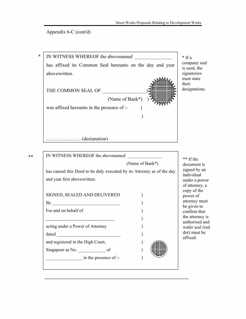
Street Works Proposals Relating to Development Works
IN WITNESS WHEREOF the abovenamed _______________
(Name of Bank*)
has caused this Deed to be duly executed by its Attorney as of the day
and year first abovewritten.
SIGNED, SEALED AND DELIVERED )
By ______________________________ )
For and on behalf of )
)
acting under a Power of Attorney )
dated ____________________________ )
and registered in the High Court, )
Singapore as No. ____________ of )
________________ in the presence of :- )
IN WITNESS WHEREOF the abovenamed _______________
has affixed its Common Seal hereunto on the day and year
abovewritten.
THE COMMON SEAL OF __________________)
(Name of Bank*) )
was affixed hereunto in the presence of :- )
)
………………… (designation)
* If a company seal is used, the signatories must state their designations.
** If the document is signed by an individual under a power of attorney, a copy of the power of attorney must be given to confirm that the attorney is authorised and wafer seal (red dot) must be affixed.
*
**
Appendix 6-C (cont'd)

Street Works Proposals Relating to Development Works
Appendix 8-A

Street Works Proposals Relating to Development Works
Appendix 8-B

Street Works Proposals Relating to Development Works
Appendix 8-C

Street Works Proposals Relating to Development Works
Appendix 8-D

Street Works Proposals Relating to Development Works
Appendix 8-E
10.0m
1.5m 1.5m 7.0m
SERVICE ROADS (FRONT / REAR)

Street Works Proposals Relating to Development Works
Appendix 8-F
CUL-DE-SAC FOR INDUSTRIAL ROADS

Street Works Proposals Relating to Development Works
Appendix 8-G

Street Works Proposals Relating to Development Works
Appendix 8-H
18.0m ROAD RESERVE AT JUNCTION

Street Works Proposals Relating to Development Works
Appendix 8-I

Street Works Proposals Relating to Development Works
Appendix 8-J

Street Works Proposals Relating to Development Works
Appendix 8-K

Street Works Proposals Relating to Development Works
Appendix 8-L

Street Works Proposals Relating to Development Works
Key Issues to be Addressed in a TIA Report
Major Heading Description of What to Include
1.0 INTRODUCTION 1.1 Background 1.2 Scope of Report 1.3 The key Issues and Objectives of
the TIA
}
} Description of the development proposal,
} study methodology, timing and output
2.0 GENERAL DATA COLLECTION / EXISTING CONDITIONS
2.1 Site Location 2.2 Description of Road Network 2.3 Existing Traffic Flow &
Conditions 2.4 Parking Supply & Demand 2.5 Public Transport 2.6 Pedestrian Network 2.7 Proposed Developments in
Vicinity
2.1 Current landuse characteristic of the site & in the
vicinity, site access 2.2 Description of road network & hierarchy, no. of
lanes, medians, on-street parking, location of bus stops etc.
2.3 AM and PM and off-peak (required only if development’s peak hour different from commuter peak) peak hour intersection and classification counts at critical intersections, maximum queue length at intersections on critical approaches. Assessment of the performance of the intersection including average delays, degree of saturation & queue length on all approaches and for the intersection without the development traffic
2.4 Current on-street parking supply & utilisation 2.5 Rail & bus stop locations & distance, pedestrian
access routes to bus stops 2.6 Identify existing pedestrian facilities & potential
conflict locations with vehicles 2.7 Approved proposed developments/
redevelopment sites adjacent to the site
3.0 PROPOSED DEVELOPMENT 3.1 The Development 3.2 Access
3.1 Nature & size of the development, projected
number of residential units, GFA of each component of development, hours & days of operations, staging and timing of development.
3.2 Development access locations, sight distance of access points & comparison with stopping and desirable minimum sight distances, projected queuing at entrances
Appendix 9-A

Street Works Proposals Relating to Development Works
3.3 Traffic Circulation & Local
System 3.4 Parking 3.5 Loading & Unloading Facilities
3.3 The new road network, improvements to existing
roads, circulation pattern & internal road layout 3.4 Proposed parking provision, parking layout,
location of carpark entry/exit barriers, projected peak demand based on survey(s) of similar sites
3.5 Provision and operation of service vehicle area
4.0 IMPACT OF PROPOSED DEVELOPMENT
4.1 Future Background Traffic 4.2 Traffic Generation 4.3 Traffic Distribution &
Assignment 4.4 Impact of Generated Traffic
4.5 Impact on Traffic Safety
4.6 Pedestrians & Other Users
4.7 Recommended Works
4.1 Estimation of future traffic volumes following
the full opening of development taking into account background traffic growth and adjacent approved developments
4.2 Estimated peak hour traffic generation based on surveys of similar sites (full survey results are to be included for reference)
4.3 Assignment of trips to the road system based on origin/destination surveys of similar or other developments in the area or another method agreeable to LTA
4.4 Projected traffic flows at key intersections for assessment years. Assessment of the performance of the intersection including the average delays, degree of saturation, reserve capacity, back of queue length on all approaches to key intersections (SIDRA output). Assessment of impact on residential amenity
4.5 Assessment of road safety impact e.g. whether a slip road should be considered at the entrance to the development to enhance safety
4.6 Provision for pedestrian crossings/overhead bridge to the bus stop & MRT
4.7 Provide suitable justifications to show need for improvement. Improvements may include site access and circulation, local improvements to road junction(s) and any other traffic management measures. These should be shown on plan(s) drawn to scale 1:500 or 1:1000. Approximate cost of recommended works to be provided
5.0 SUMMARY & CONCLUSION
A technical summary that concisely sums up the study purpose, conclusions and recommendations
Appendix 9-A (cont'd)