development and testing of an ultracapacitor based uninterruptible power supply … · ·...
TRANSCRIPT

Dennis J. EichenbergGlenn Research Center, Cleveland, Ohio
Development and Testing of an Ultracapacitor BasedUninterruptible Power Supply (UPS) System
NASA/TM—2010-216780
July 2010

NASA STI Program . . . in Profi le
Since its founding, NASA has been dedicated to the advancement of aeronautics and space science. The NASA Scientifi c and Technical Information (STI) program plays a key part in helping NASA maintain this important role.
The NASA STI Program operates under the auspices of the Agency Chief Information Offi cer. It collects, organizes, provides for archiving, and disseminates NASA’s STI. The NASA STI program provides access to the NASA Aeronautics and Space Database and its public interface, the NASA Technical Reports Server, thus providing one of the largest collections of aeronautical and space science STI in the world. Results are published in both non-NASA channels and by NASA in the NASA STI Report Series, which includes the following report types: • TECHNICAL PUBLICATION. Reports of
completed research or a major signifi cant phase of research that present the results of NASA programs and include extensive data or theoretical analysis. Includes compilations of signifi cant scientifi c and technical data and information deemed to be of continuing reference value. NASA counterpart of peer-reviewed formal professional papers but has less stringent limitations on manuscript length and extent of graphic presentations.
• TECHNICAL MEMORANDUM. Scientifi c
and technical fi ndings that are preliminary or of specialized interest, e.g., quick release reports, working papers, and bibliographies that contain minimal annotation. Does not contain extensive analysis.
• CONTRACTOR REPORT. Scientifi c and
technical fi ndings by NASA-sponsored contractors and grantees.
• CONFERENCE PUBLICATION. Collected papers from scientifi c and technical conferences, symposia, seminars, or other meetings sponsored or cosponsored by NASA.
• SPECIAL PUBLICATION. Scientifi c,
technical, or historical information from NASA programs, projects, and missions, often concerned with subjects having substantial public interest.
• TECHNICAL TRANSLATION. English-
language translations of foreign scientifi c and technical material pertinent to NASA’s mission.
Specialized services also include creating custom thesauri, building customized databases, organizing and publishing research results.
For more information about the NASA STI program, see the following:
• Access the NASA STI program home page at http://www.sti.nasa.gov
• E-mail your question via the Internet to help@
sti.nasa.gov • Fax your question to the NASA STI Help Desk
at 443–757–5803 • Telephone the NASA STI Help Desk at 443–757–5802 • Write to:
NASA Center for AeroSpace Information (CASI) 7115 Standard Drive Hanover, MD 21076–1320

Dennis J. EichenbergGlenn Research Center, Cleveland, Ohio
Development and Testing of an Ultracapacitor BasedUninterruptible Power Supply (UPS) System
NASA/TM—2010-216780
July 2010
National Aeronautics andSpace Administration
Glenn Research CenterCleveland, Ohio 44135
Available from
NASA Center for Aerospace Information7115 Standard DriveHanover, MD 21076–1320
National Technical Information Service5301 Shawnee Road
Alexandria, VA 22312
Available electronically at http://gltrs.grc.nasa.gov
Trade names and trademarks are used in this report for identifi cation only. Their usage does not constitute an offi cial endorsement, either expressed or implied, by the National Aeronautics and
Space Administration.
Level of Review: This material has been technically reviewed by technical management.

NASA/TM—2010-216780 1
Development and Testing of an Ultracapacitor Based Uninterruptible Power Supply (UPS) System
Dennis J. Eichenberg
National Aeronautics and Space Administration Glenn Research Center Cleveland, Ohio 44135
Summary
The NASA Glenn Research Center (GRC) initiated the development and testing of an ultracapacitor based uninterruptible power supply (UPS) system as a means to provide backup power for the many critical NASA applications. A UPS system typically utilizes batteries for energy storage. The battery is the most vulnerable part of the UPS system, requiring regular maintenance and replacement. Battery performance is also extremely temperature dependent. Ultracapacitors are ideal for UPS systems where long life, maintenance free operation, and excellent low temperature performance is essential.
State of the art symmetric ultracapacitors were used for these tests. The ultracapacitors were interconnected in an innovative configuration to minimize interconnection impedance, and to provide voltage balancing. Ultracapacitors can be charged extremely rapidly and supply high current, which are essential characteristics for an effective UPS system. Charging ultracapacitors is significantly less complex than charging batteries since there is no chemical reaction occurring while charging ultracapacitors. The report concludes that the implementation of symmetric ultracapacitors in a UPS system can provide significant improvements in power system performance and reliability.
Introduction
The NASA Glenn Research Center has a wealth of experience in ultracapacitor technology through the Hybrid Power Management (HPM) Program (Ref. 1). The Electrical and Electromagnetics Branch of the Avionics and Electrical Systems Division initiated the HPM Program for the Technology Transfer and Partnership Office. Hybrid Power Management is the innovative integration of diverse, state-of-the-art power devices in an optimal configuration for space and terrestrial applications. The appropriate application and control of the various power devices significantly improves overall system performance and efficiency. The advanced power devices include ultracapacitors and power conditioning equipment. HPM has extremely wide potential. Applications include power generation, transportation systems, biotechnology systems, and space power systems. HPM has the potential to significantly alleviate global energy concerns, improve the environment, and stimulate the economy.
One of the unique power devices being utilized by HPM for energy storage is the ultracapacitor. A capacitor is an electrical energy storage device consisting of two or more conducting electrodes separated from one another by an insulating dielectric. An ultracapacitor is an electrochemical energy storage device, which has extremely high volumetric capacitance energy due to high surface area electrodes, and very small electrode separation. Ultracapacitors have many advantages over batteries.

NASA/TM—2010-216780 2
Batteries can only be charged and discharged hundreds of times, and then must be replaced. Ultracapacitors can be charged and discharged over 1 million times. The long cycle life of ultracapacitors greatly improves system reliability, and reduces life-of-system costs.
Long ultracapacitor life significantly reduces environmental impact, as ultracapacitors will probably never need to be replaced and disposed of in most applications.
The environmentally safe components of ultracapacitors greatly reduce disposal concerns.
High ultracapacitor power density provides high power during surges, and the ability to absorb high power during recharging. Ultracapacitors are extremely efficient in capturing recharging energy.
Ultracapacitors are extremely rugged, reliable, and maintenance free. Ultracapacitors have excellent low temperature characteristics. Ultracapacitors provide consistent performance over time. Ultracapacitors promote safety, as they can easily be discharged, and left indefinitely in
a safe discharged state.
Hybrid Power Management has been successfully applied to the NASA Hybrid Electric Transit Bus (HETB) project. This is a 40-ft transit bus with a unique hybrid drive. At over 37,000-lb. gross weight, this is the largest vehicle to ever use ultracapacitor energy storage. The ultracapacitor technology utilized for the HETB is being applied to satellite actuation to replace unreliable hydraulic systems. The motor and control technology utilized for the HETB is being applied to flywheel dynamometer systems.
Hybrid Power Management has been utilized to provide power for drop tower research. HPM is being considered for space missions, such as the exploration of Mars, and deep space missions, such as the exploration of Europa.
Through the NASA Glenn Research Center Technology Transfer and Partnership Office, HPM is being applied to power generation, transportation, safety, and biotechnology systems. Some specific examples include photovoltaic power generation, electric vehicles, and safety systems.
An UPS is an electrical apparatus that provides emergency power to a load when the input power source, typically the utility power system, fails. The UPS provides near instantaneous protection from power interruptions by means of a backup energy storage system and the associated electronic circuitry. The UPS typically provides power for a few minutes to permit an orderly shutdown of the protected equipment.
Uninterruptible power supply systems typically use batteries for energy storage, although flywheels and fuel cells have also been used successfully. All of these energy storage systems require regular maintenance and replacement, which is not the case with ultracapacitor energy storage, making it an ideal candidate for UPS systems.
Test Objectives
Testing of the prototype ultracapacitor UPS system was performed at the NASA Glenn Research Center. Of particular interest is the performance of an ultracapacitor bank in conjunction with an UPS and a dc power supply for charging the ultracapacitors.

NASA/TM—2010-216780 3
Test Hardware Description
The UPS utilized for these tests is an efficient, compact, maintenance free, rack mount, pure sine wave inverter unit. The UPS is shown in Figure 1 and described in detail in Appendix A. The UPS provides a continuous output power up to 1700 W with a surge rating of 1870 W for up to 1 min at a nominal output voltage of 115 Vac.
The ultracapacitor energy storage system tested in conjunction with the UPS is rated at 5.8 Farads. This is a bank of ten symmetric ultracapacitor modules, and is shown in Figure 2 and described in detail in Appendix A. An individual ultracapacitor module is shown in Figure 3 and described in detail in Appendix A. Each module is actively balanced utilizing a linear voltage balancing technique, in which the cell-to-cell leakage is dependent upon the imbalance of the individual cells. This state-of-the-art technology not only has much longer life than conventional batteries, but also provides much higher current capacity than batteries. Ultracapacitors are reliable, maintenance free, and have excellent low temperature characteristics.
Figure 1.—Complete Prototype Ultracapacitor UPS System.

NASA/TM—2010-216780 4
Figure 2.—Bank of Ten Ultracapacitors for the Prototype UPS System.
Figure 3.—Single Ultracapacitor for the Prototype UPS System.

NASA/TM—2010-216780 5
Figure 4.—Ultracapacitor UPS System Test Configuration Block Diagram.
The ultracapacitors are charged by a dc power supply. The power supply can provide up to
300 Vdc at 4 A. A constant voltage, constant current power supply was selected for this application. The power supply is shown in Figure 1 and described in detail in Appendix A.
A block diagram of the UPS system is shown in Figure 4.
Instrumentation
The UPS, ultracapacitor bank, charger, and load bank were instrumented to measure UPS performance, ultracapacitor performance, and charger performance. Data from the UPS, ultracapacitor bank, charger, and load bank were sent to a digital data acquisition system, sampled continuously, and stored on a PC. Data channels measured UPS voltage and current, ultracapacitor voltage and current, charger voltage and current, and load bank voltage and current. Ambient temperature was also measured. The instrumentation configuration is described in Appendix B.
Test Procedures
The tests described in this report were conducted at the NASA Glenn Research Center in Cleveland, Ohio. A description of the tests is given in Appendix C. The tests were conducted in accordance with the test matrix provided in Appendix D.
UNINTERRUPTIBLE POWER SUPPLY
ULTRACAPACITOR
BANK ENERGY FLOW
LOAD BANK
AC POWER SOURCE
CHARGER

NASA/TM—2010-216780 6
Test Results
System Performance
Seven tests were conducted to determine ultracapacitor UPS system performance, per Table 1:
TABLE 1.—PERFORMANCE TESTS CONDUCTED ON THE ULTRACAPACITOR UPS SYSTEM Test
number Energy source Ultracapacitor
bank Load Test mode
1 dc Power supply Series of 10 N/A Charge test 2 Ultracapacitors Series of 10 None Self discharge test 3 Ultracapacitors Series of 10 None Balance test 4 ac Source Series of 10 99.1 Load test 5 Ultracapacitors Series of 10 99.1 Load test 6 ac Source Series of 10 99.1 UPS efficiency 7 Ultracapacitors Series of 10 99.1 s UPS efficiency
Plots have been included in Appendix E for the various system tests:
a. Charging test results b. Load test results c. Self discharge test results
A summary of the test results is shown in Table 2 at the end of this section.
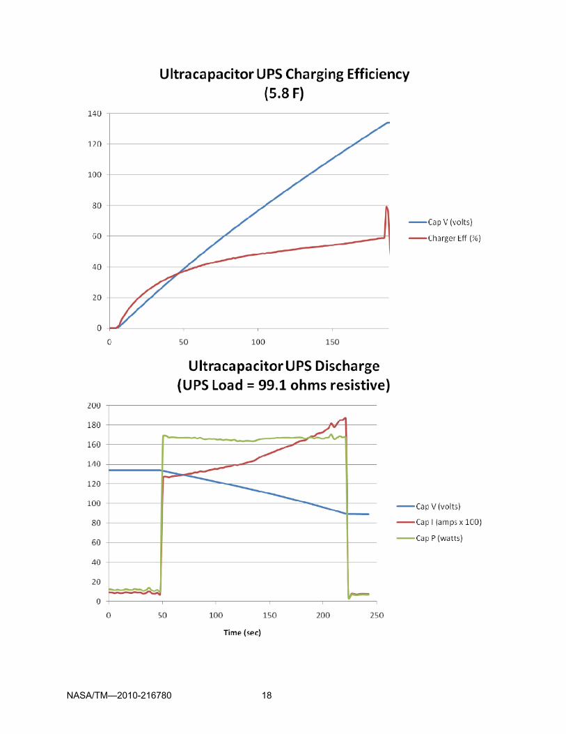
Charge Test
The bank of ten ultracapacitors was charged to 134.0 Vdc at a current limit of 4 A with a constant voltage, constant current dc power supply. The ultracapacitors were completely discharged prior to the test. The time to charge the bank of ultracapacitors under these conditions was 180 sec. A dc power supply with greater current capacity could be used to charge the bank of ultracapacitors faster, although the ultracapacitors are limited to a maximum current of 1,500 A. Higher charging current also results in higher ultracapacitor temperature, which is limited to 65 C. Higher charging current also requires larger conductors and connectors to handle the higher current levels. A dc power supply with a lower current capacity could be used to charge the bank of ultracapacitors at a slower rate. Such a power supply would be smaller, less expensive, and produce less heat.
The 134.0 Vdc, 4 A power supply efficiency was quite low when the completely discharged ultracapacitor bank charging was initiated, and increased as the ultracapacitor bank voltage increased. The dc power supply average efficiency was 41.1 percent and the maximum efficiency was 59.2 percent.
The voltage of each of the ten ultracapacitors was monitored individually during the charge test as a balance test. The average voltage was 13.40 V, the minimum voltage was 13.26 V, and the maximum voltage was 13.82 V.
Charge and balance test results are indicated in Table 2.
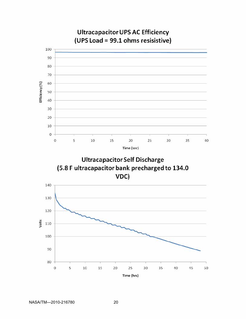
Self Discharge Test
The self discharge of the bank of ten ultracapacitors was determined at no load with the ultracapacitors precharged to 134.0 V. The bank discharged to the minimum operating voltage of the UPS, which is 90 V, in 45.5 hr.
Self discharge results are indicated in Table 2.

NASA/TM—2010-216780 7
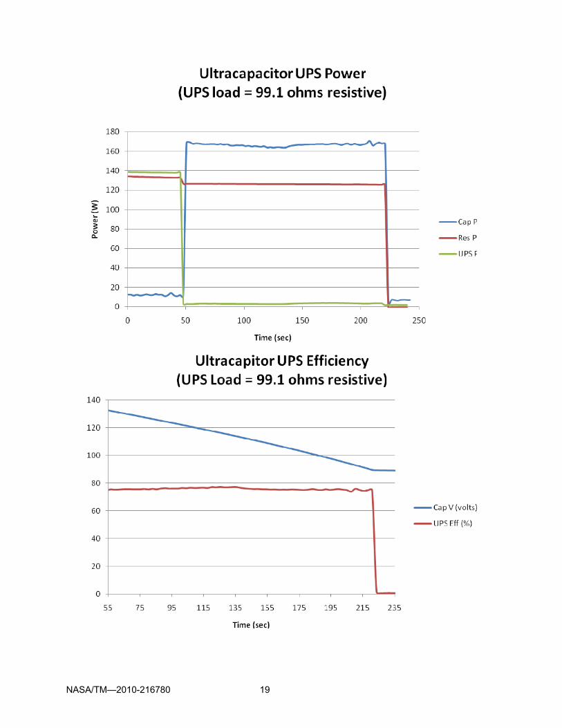
Load Test
The UPS was tested with the output set to 115.2 Vac. The load was 99.1 . The UPS system was first operated with ac power and the bank of ten ultracapacitors precharged to 134.0 Vdc, which is the maximum operating voltage of the UPS. The efficiency of the ac operation was determined to be an average of 96.6 percent, and very constant under all operating conditions. The ac power system was then switched off, and the UPS system automatically switched to dc operation from the bank of ultracapacitors. The efficiency of the UPS system with the dc power source was determined to be an average of 75.8 percent and very constant under all operating conditions. The operating time for the UPS with the bank of ultracapacitors was 170.3 sec, limited by the voltage of the ultracapacitors. Increased capacitance of the ultracapacitor bank, easily accomplished through paralleling additional ultracapacitors, would increase the UPS operating time. Expanding the operating voltage range of the UPS system would also increase the UPS operating time.
Discharge times are indicated in Table 2.
Summary
An overall summary of the UPS testing is shown in Table 2.
TABLE 2.—SUMMARY OF TEST RESULTS FOR THE ULTRACAPACITOR UPS SYSTEM Parameter Configuration Test conditions Test results Remarks
Charge test Time DC power supply
and bank of ten ultracapacitors
134.0 Vdc at 4 A output
180 sec Ultracapacitors completely discharged to start
Efficiency
AC power supply and bank of ten ultracapacitors
120 Vac input 41.1% Av 59.2% Max
Power supply efficiency
AC source load test Efficiency
120 Vac input 99.1 load 96.6% Av
DC source load test Efficiency Bank of ten
ultracapacitors
99.1 load 75.8% Av Ultracapacitors precharged to 134.0 Vdc and discharged to 90 Vdc
Time Bank of ten ultracapacitors
99.1 load 170.3 sec Ultracapacitors discharged to 90 Vdc
Self discharge test Time Bank of ten
ultracapacitors No load 45.5 hrs 134.0 to 90 Vdc
Balance test Average voltage Minimum voltage Maximum voltage
Bank of ten ultracapacitors
No load 13.40 Vdc 13.26 Vdc 13.82 Vdc
Ultracapacitors precharged to 134.0 Vdc

NASA/TM—2010-216780 8
Concluding Remarks
The prototype ultracapacitor UPS system has been tested very successfully with symmetric ultracapacitor energy storage. The primary focus of this report is the test results with symmetric ultracapacitor energy storage. The UPS, nor the energy storage system, nor the charging system, exhibited any problems under the rigorous test conditions that it was exposed to. The performance of the UPS and the ultracapacitor bank proved to be excellent.
The bank of ten ultracapacitor modules was assembled to provide a maximum voltage rating of 150.0 V to match the maximum input voltage rating of the UPS. The modules were connected in a fashion to minimize interconnection impedance. Each module is actively balanced using a linear voltage-balancing technique. The bank of ultracapacitors were completely discharged, and then charged to 134.0 Vdc, which is the maximum operating voltage of the UPS, with a constant voltage constant current power supply set to 4 A. The bank of ultracapacitors charged in 180 sec under these conditions. The efficiency of the charger was an average of 41.1 percent with a maximum of 59.2 percent. Ultracapacitors can typically be charged much more efficiently than batteries because there is no chemical reaction taking place when charging ultracapacitors. A much more efficient charger can be developed for this application with existing technology to provide a charging efficiency exceeding 90 percent. The bank of ultracapacitors balanced extremely well with an average voltage of 13.40 V, a minimum voltage of 13.26 V, and a maximum voltage of 13.82 V. The bank of ultracapacitors were charged and discharged numerous times without failure.
The self discharge of the bank of ten ultracapacitors was determined at no load with the ultracapacitors precharged to 134.0 V. The bank discharged to the minimum operating voltage of the UPS, which is 90 V, in 45.5 hr. In typical UPS systems, the ultracapacitors would be continuously charged to 134.0 V to provide the maximum UPS operating time. The low self discharge of the ultracapacitors minimizes the power requirement for maintaining the ultracapacitor charge.
The UPS was tested with the output set to 115.2 Vac with a load of 99.1 . The UPS system was first operated with ac power and the bank of ten ultracapacitors precharged to 134.0 Vdc. The efficiency of the ac operation was determined to be an average of 96.6 percent, and very constant under all operating conditions. The ac power system was then switched off, and the UPS system automatically switched to dc operation from the bank of ultracapacitors. The efficiency of the UPS system with the dc power source was determined to be an average of 75.8 percent and very constant under all operating conditions. The operating time for the UPS with the bank of ultracapacitors was 170.3 sec, limited by the voltage of the ultracapacitors. This operating time is adequate for most UPS applications. Increased capacitance of the ultracapacitor bank, easily accomplished through paralleling additional ultracapacitors, would increase the UPS operating time. Expanding the operating voltage range of the UPS system would also increase operating time.
Ultracapacitors are ideal energy storage system for UPS systems due to their exceptionally long cycle life, high reliability, high efficiency, high power density, ease of charging, and excellent low temperature performance.
References
1. Eichenberg, D.J., “Hybrid Power Management (HPM),” NASA Technical Memorandum 2007-214913, August 2007.

NASA/TM—2010-216780 9
Appendix A.—Equipment Under Test Summary Data Sheet
1.0 Uninterruptible Power Supply (UPS)—Schaefer Model AEP-U2000R-1101
1.1 Continuous output power 1700 W (2 KVA) 1.2 Surge rating 1870 W for 1 min 1.3 Input voltage 90 to 140 Vdc 1.4 Output voltage regulation 100 to 120 Vac RMS 2% 1.5 Frequency (Switch selectable) 50/60 Hz0.05% 1.6 Peak output current 25 A 1.7 Low voltage alarm 95 Vdc 1.8 High voltage alarm 135 Vdc 1.9 Low voltage shutdown 90 Vdc 1.10 Full load efficiency 90% 1.11 Output waveform <3% THD sine wave (resistive load) 1.12 Output voltage range 100 to 120 Vac 1.13 Power factor 0.85 1.14 Output protection Overload, short circuit 1.15 Input protection Over/under voltage 1.16 Internal protection Over temperature 1.17 AC input voltage 90 to 130 Vac, single phase 1.18 AC input frequency 50 to 60 Hz 1.19 Bypass time 4 to 6 ms 1.20 Operating temperature –30 to 60 C (–22 to 140 F) 1.21 Storage temperature –30 to 70 C (–22 to 158 F) 1.22 Weight 9.8 kg (21.6 lb) 1.23 Height 88.4 mm (3.48 in.) 1.24 Width 424.0 mm (19.0 in.) 1.25 Depth 435.0 mm (17.12 in.) 1.26 Control interface RS-232C
2.0 Ultracapacitor—Maxwell Model BMOD0058-E015-B01 2.1 Configuration Symmetric, dual layer, module 2.2 Capacitance 58 F 2.3 Energy rating 6.525 kJ 2.4 Voltage rating 15 V continuous 2.5 Maximum series resistance 19.0 m 2.6 Maximum specific power density 8.2 kW/kg 2.7 Maximum specific energy density 2.67 Wh/kg 2.7 Maximum current 1500 A 2.8 Leakage current 1.0 mA 2.9 Operating temperature –40 to 65 C (–40 to 149 F) 2.10 Storage temperature –40 to 70 C (–40 to 158 F)
2.11 Height 44.0 mm (1.73 in.) 2.12 Width 85.0 mm (3.35 in.) 2.13 Depth 218.0 (8.58 in.) 2.14 Weight 680.0 g (1.50 lb)

NASA/TM—2010-216780 10
3.0 Ten Ultracapacitor Bank—Maxwell Model BMOD0058-E015-B01
3.1 Configuration 10 series ultracapacitor modules 3.2 Capacitance 5.8 F 3.3 Energy rating 65.25 kJ 3.4 Voltage rating 150 V continuous 3.5 Maximum series resistance 190.0 m 3.6 Maximum specific power density 8.2 kW/kg 3.7 Maximum specific energy density 2.67 Wh/kg 3.8 Maximum current 1500 A 3.9 Leakage current 1.0 mA 3.10 Operating temperature –40 to 65 C (–40 to 149 F) 3.11 Storage temperature –40 to 70 C (–40 to 158 F)
3.12 Height 44.0 mm (1.73 in.) 3.13 Width 850.0 mm (33.5 in.) 3.14 Depth 218.0 (8.58 in.) 3.15 Weight 6.8 kg (15.0 lb)
4.0 Charger—Xantrex Model XFR-300-4
4.1 Configuration Constant voltage, constant current 4.2 Input voltage 85 to 130 Vac, single phase, 60 Hz 4.3 Output voltage 0 to 300 Vdc 4.4 Output current 0 to 4 Adc 4.5 Weight 8.16 kg (18.0 lb) 4.6 Height 44.4 mm (1.75 in.) 4.7 Width 482.6 mm (19.0 in.) 4.8 Depth 444.5 mm (17.5 in.)

NASA/TM—2010-216780 11
Appendix B.—Description of the Instrumentation System
A block diagram of the instrumentation system is shown in Figure 5. All measurements were obtained with an Agilent Model 34970A data acquisition system.
Type K thermocouples were used for all temperature measurements. Hall Effect transducers were used for all current measurements. These data were transmitted to a PC via a serial interface. The PC logged the data.
A 99.1 , 250 W power resistor was used for all load tests. A Xantrex XFR 300 V, 4 A power supply was used to precharge the ultracapacitors when necessary.
Figure 5.—Ultracapacitor UPS Instrumentation System.


NASA/TM—2010-216780 13
Appendix C.—Description of Digital Data Acquisition System
The digital data acquisition system used for testing is an Agilent Model 34970A. It is a high performance, microprocessor controlled, portable, data acquisition system. It consists of a half-rack mainframe with an internal 61/2-digit (22 bit) digital multimeter. Three module slots are built into the rear of the unit to accept a combination of switch and control modules.
Tests documented in this report were conducted with the digital data acquisition system programmed to meet the test matrix requirements.


NASA/TM—2010-216780 15
Appendix D.—Description of Test Cycles
Testing of the system was based on the test matrix shown in Table 3.
TABLE 3.—ULTRACAPACITOR UPS TEST MATRIX Parameter Conditions
Charge test Bank of ten ultracapacitors charged by a dc power supply to 134.0 Vdc limited to 4 A.
Load test UPS connected to a 99.1 load. Power provided by 120 Vac power source, then 120 Vac power source disconnected, automatically transferring power source to a bank of ultracapacitors precharged to 134.0 Vdc.
Self discharge test Self discharge bank of ten ultracapacitors precharged to 134.0 Vdc and discharged to 90.0 Vdc.
Balance test Voltage of individual ultracapacitors precharged as a bank of ten ultracapacitors to 134.0 Vdc.


NASA/TM—2010-216780 17
Appendix E.—System Performance Test Results
A complete set of plots of the test results are included here. Table 1 identifies the tests that were conducted.
NASA/TM—2010-216780 18
NASA/TM—2010-216780 19
NASA/TM—2010-216780 20

REPORT DOCUMENTATION PAGE Form Approved
OMB No. 0704-0188 The public reporting burden for this collection of information is estimated to average 1 hour per response, including the time for reviewing instructions, searching existing data sources, gathering and maintaining the data needed, and completing and reviewing the collection of information. Send comments regarding this burden estimate or any other aspect of this collection of information, including suggestions for reducing this burden, to Department of Defense, Washington Headquarters Services, Directorate for Information Operations and Reports (0704-0188), 1215 Jefferson Davis Highway, Suite 1204, Arlington, VA 22202-4302. Respondents should be aware that notwithstanding any other provision of law, no person shall be subject to any penalty for failing to comply with a collection of information if it does not display a currently valid OMB control number. PLEASE DO NOT RETURN YOUR FORM TO THE ABOVE ADDRESS.
1. REPORT DATE (DD-MM-YYYY) 01-07-2010
2. REPORT TYPE Technical Memorandum
3. DATES COVERED (From - To)
4. TITLE AND SUBTITLE Development and Testing of an Ultracapacitor Based Uninterruptible Power Supply (UPS) System
5a. CONTRACT NUMBER
5b. GRANT NUMBER
5c. PROGRAM ELEMENT NUMBER
6. AUTHOR(S) Eichenberg, Dennis, J.
5d. PROJECT NUMBER
5e. TASK NUMBER
5f. WORK UNIT NUMBER WBS 392259.02.03.0485.09
7. PERFORMING ORGANIZATION NAME(S) AND ADDRESS(ES) National Aeronautics and Space Administration John H. Glenn Research Center at Lewis Field Cleveland, Ohio 44135-3191
8. PERFORMING ORGANIZATION REPORT NUMBER E-17406
9. SPONSORING/MONITORING AGENCY NAME(S) AND ADDRESS(ES) National Aeronautics and Space Administration Washington, DC 20546-0001
10. SPONSORING/MONITOR'S ACRONYM(S) NASA
11. SPONSORING/MONITORING REPORT NUMBER NASA/TM-2010-216780
12. DISTRIBUTION/AVAILABILITY STATEMENT Unclassified-Unlimited Subject Category: 44 Available electronically at http://gltrs.grc.nasa.gov This publication is available from the NASA Center for AeroSpace Information, 443-757-5802
13. SUPPLEMENTARY NOTES
14. ABSTRACT The NASA Glenn Research Center (GRC) initiated the development and testing of an ultracapacitor based uninterruptible power supply (UPS) system as a means to provide backup power for the many critical NASA applications. A UPS system typically utilizes batteries for energy storage. The battery is the most vulnerable part of the UPS system, requiring regular maintenance and replacement. Battery performance is also extremely temperature dependent. Ultracapacitors are ideal for UPS systems where long life, maintenance free operation, and excellent low temperature performance is essential. State of the art symmetric ultracapacitors were used for these tests. The ultracapacitors were interconnected in an innovative configuration to minimize interconnection impedance, and to provide voltage balancing. Ultracapacitors can be charged extremely rapidly and supply high current, which are essential characteristics for an effective UPS system. Charging ultracapacitors is significantly less complex than charging batteries since there is no chemical reaction occurring while charging ultracapacitors. The report concludes that the implementation of symmetric ultracapacitors in a UPS system can provide significant improvements in power system performance and reliability.15. SUBJECT TERMS Electrochemical capacitors; Electric energy storage; Power conditioning
16. SECURITY CLASSIFICATION OF: 17. LIMITATION OF ABSTRACT UU
18. NUMBER OF PAGES
23
19a. NAME OF RESPONSIBLE PERSON STI Help Desk (email:[email protected])
a. REPORT U
b. ABSTRACT U
c. THIS PAGE U
19b. TELEPHONE NUMBER (include area code) 443-757-5802
Standard Form 298 (Rev. 8-98)Prescribed by ANSI Std. Z39-18

