developing physical solutions for infosphere master data ... · workbench. if you have not used the...
TRANSCRIPT

Developing Physical Solutions for InfoSphere Master Data Management Server Advanced Edition v11
MDM Workbench Development Tutorial
Copyright IBM 2013
John Beaven/UK/IBM2013
Page 1 Copyright IBM 2013

Contents
Overview 3Machine Requirements 4System Configuration 4Changes in Version 11 5Some up-front Terminology 5Solution Overview 7
Step 1 - Setting up the Workspace 8Step 2 – Configuring the Server Connection 10Step 3 - Creating the “Development Model” 12Step 4 - Creating the four new Entity Types 14
An introduction to containment structures 16
Step 5 - Creating “containment” relationships 17Step 6 – New Code Table & Type Code for Room 20Step 7 - Extending the “Person” entity type 22Step 8 - Enforcing ‘addPerson’ transaction validation 24Step 9 - Generating code from the model 27Step 10 - Implementing the behaviour extension 28Step 11 - Customizing the Code Table values 29Step 12 - Deploying the code 32Step 13 - Deploying the metadata configuration 37Step 14 - Testing the Solution 42
Page 2 Copyright IBM 2013

Overview
In modern businesses, the volume of information being managed by an organization is increasing whilst at the same time this information is becoming ever more critical to a businesses success.
If this information is not managed and controlled, there is the potential for companies to make vital decisions based on incorrect data or become over whelmed by the scale of the information.
Master Data Management (MDM) solutions can provide a single, trusted view of critical business data and help organizations meet growth, revenue-generation and cost-reduction goals.
The MDM Server provides such a solution with a comprehensive range of out of the box services that help businesses manage and control their information.
The MDM Workbench allows these services to be enhanced or extended to tailor the capabilities for a specific deployment.
This tutorial shows how the MDM Workbench can be used to design a model of these additional capabilities and how these can be deployed to the MDM Server.
No prior experience of either the MDM Server or MDM Workbench is assumed
The instructions in this tutorial are broken down into two types of information. Those sections marked with a 'textpad' icon contain background information that you can choose to skip if if time is pressing and refer to later:
(BACKGROUND!)
Those sections marked with a 'user' icon contain the key steps that must be followed to complete the tutorial:
(KEY STEPS!)
Page 3 Copyright IBM 2013

Machine Requirements
The requirements for running MDM V11 are as follows:
• 8GB-12GB of memory• 50GB of dedicated disk space required for a typical installation
To set-up a machine for this tutorial, if MDM is not already installed, then it is recommended to run a 'Typical Installation'. Instructions for this can be found by following the link below:
https://www.ibm.com/developerworks/community/blogs/64033fdd-4a35-4733-852f-a39abcdf4fb3/entry/installing_mdm_workbench_v11?lang=en
System Configuration
This tutorial assumes you have completed a typical installation of MDM V11 including the software listed below:
• IBM Rational Application Developer for WebSphere Software Version 8.5.1• IBM WebSphere Application Server Version 8.5.0.2• IBM InfoSphere Master Data Management Workbench Version 11• InfoSphere MDM Standard Edition or Advanced Edition Version 11• IBM DB2 Version 10.1
For a typical installation the default user ids and passwords are as follows:
• DB2 User ID: db2admin• DB2 Password: db3Admin• WebSphere User ID: mdmadmin• WebSphere Password: mdmadmin
Page 4 Copyright IBM 2013

Changes in Version 11 (BACKGROUND!)
What’s this section about? Discusses some changes since the last version of the workbench. If you have not used the workbench before you can skip this section.
One of the most apparent changes when using the latest version of the workbench is that you no longer need to use the DEST utility to prepare the development environment. Unlike previous releases where an MDM Enterprise Archive (EAR) was unpacked into the workspace, version 11 uses an Enterprise Bundle Archive (EBA) stored outside the workspace to provide the basis for development. The necessary dependencies on the EBA are established automatically when the workbench is installed. Modules developed in the workspace are combined into a Composite Bundle Archive (CBA) which can be deployed alongside the main server EBA to customize MDM.
Some up-front Terminology (BACKGROUND!)
What’s this section about? Provides an introduction to some of the core components that make up a solution. Skip this section if required and refer to it as necessary.
Entity Type – A physical entity in the MDM data model. As supplied the MDM Server supports a range of different Entity Types such as Person, Contract or Group. Additional Entity Types may be created in the Workbench to extend the data model.
Attribute – A field defined for an Entity Type or Entity Type Extension
Entity Type Extension – An extension to an out of the box Entity Type. Typically this mechanism is used to add additional attributes required by a solution that are not present in the out of the box data model. For example, if a Contract needed an additional contract classification field, an Entity Type Extension could be defined to add this. This should not be confused with a subtype, which is a separate concept. Creating an Entity Type Extension of Contract allows additional fields to be added to requests and responses that include instances of a Contract. The extension however is not considered to be a separate type in its own right. Additional fields are included in a generic “extended block” that’s common to all Entity Type definitions.
Code Table – A structure used to contain a set of String values that can be referred to by a Type Code. Conceptually similar to an enumeration in Java, these structures are used to hold well defined sets of values that don’t change often. For example, we could create a Code Table to hold a set of colors (“Red”, “Green”, “Blue”, “Orange”) Once deployed each Code Table entry has both a “value” – the String representation
Page 5 Copyright IBM 2013

and a “type” – essentially the numerical database key. For example, (1, Red) or (2, Green)
Type Code – A reference to an entry within a Code Table. When referencing a Code Table, either the Code Table “Type” or “Value” may be specified. If both are present, they must match.
Transaction – A service or operation that can be executed by a client on the MDM Server. For example, when adding a person to the database, users would invoke the “addPerson” transaction. XML is used to define a request which can be passed to the server over a number of different interfaces (eg a WebService call)
Behaviour Extension – Allows the default services provided by MDM to customized by executing code before and/or after the core service runs. For example, we could add additional validation to ensure that specific constrains are met when performing an addContract transaction.
Page 6 Copyright IBM 2013

Solution Overview (BACKGROUND!)
What’s this section about? Provides an outline of the solution that you will build in this tutorial. If time is pressing, you can skip this and simply follow the instructions in further sections below. Its recommended that you do at least review the model diagram in this section.
For this tutorial, we have created a simplified model that consists of a range of different elements supported by the workbench. The tutorial shows how this model is defined and converted into code. It demonstrates how this code can be modified to customize the solution and how this can then be deployed to and tested on a server.
To keep things simple and allow you to focus on the mechanics involved, we minimized the amount of additional complexity that might be found in a real-world scenario. During the course of this of this tutorial we will build following model:
This model reflects a simplified asset tracking system used to manage machinery in a factory complex.
Site – A new Entity Type introduced to hold information about a factory or plant location.
Building – A new Entity Type used to hold details about a building at a Site
Room – A new Entity Type used to hold details of a specific Room within a Building
MachineAsset – A new Entity Type used to hold details of a physical machine asset within a room.
Page 7 Copyright IBM 2013

RoomType – A Code Table used to define the set of possible room classifications (“Office”, “PlantRoom”, “MeetingRoom”, “StoreRoom”)
XPerson – MDM provides an “of the box” Entity Type called Person that holds details of individuals that exist in the database. XPerson is an Entity Type Extension of Person that defines an extra attribute not present in the standard data model. In this case, it’s a field that indicates if a person has been certified to operate heavy machinery.
MinimumAgeCheck - Behaviour extension to ensure that all employees are over 16. Additional logic will run prior to the “addPerson” transaction to enforce this.
Step 1 - Setting up the Workspace (KEY STEPS!)
What’s this section about? The workspace will be prepared for development. You must follow these steps to complete the tutorial.
● Start RAD or RSA by running the application from the Desktop or Start menu
● When the “Workspace Launcher” dialog appears, select a new folder to contain the projects developed in this tutorial and click OK
Page 8 Copyright IBM 2013

Each time a brand new workspace is opened, the Configuring the WebSphere Application Server dialog will appear. The next steps show how to use this to create a connection to the WebSphere server configured on the local machine:
● In the Configuring the WebSphere Application Server dialog, ensure the “Add WebSphere Application Server V8.5 configuration to the workspace” option is checked.
● Specify the user id and password, for a typical installation the defaults are “mdmadmin” and password “mdmadmin” under the authentication settings and click Finish
● Once the workspace opens, close the Welcome screen by clicking on the cross on the Welcome tab.
Page 9 Copyright IBM 2013

You should now see an empty workspace as shown below:
New “Development Projects” are created in here and
contain models and code developed in the workspace
Resources being edited appear in the right hand panel
The Servers tab provides control over the WebSphere application server
The Problems tab shows details of any errors
Step 2 – Configuring the Server Connection (KEY STEPS!)
What’s this section about? The WebSphere server connection definition will be updated to control how code is deployed from the workspace to the server
The server connection created by the “Configuring the WebSphere Application Server” dialog above needs some fine tuning. We need to change the settings so that binary code developed in the workspace is copied to the WAS server rather than being linked to it. The distinction may seem subtle, but the effect is to de-couple code developed in the workspace with the code deployed on the server. The server deployment will remain valid and functional even if the workspace is deleted (if it was linked to a workspace that was deleted, this would cause problems). The following steps show how to do this:
● Open the Servers view from the RSA main menu Window -> Show View -> Servers
Page 10 Copyright IBM 2013

● Double click on the WebSphere Application Server v8.5 in Servers view to open the configuration settings for the server connection.
● Under Publishing settings for WebSphere Application Server, ensure the Run server with resources on Server option is selected.
● Close the WebSphere Application Server v8.5 configuration
● Save the configuration settings when prompted by clicking Yes
The workspace is now configured and you are ready to start developing code!
Page 11 Copyright IBM 2013

Step 3 - Creating the “Development Model” (KEY STEPS!)
What’s this section about? A new Development project containing a development model (previously referred to as a Hub Model) will be created in the workspace. You must follow these steps to complete the tutorial.
● Open the “context menu” (right hand mouse button) in the Package Explorer or Navigator view (left hand portion of RAD window)
● Select New -> Other… from the menu
● In the New wizard, select Master Data Management ->Development Project wizard and click Next
● In the New Master Data Management Development Project window enter the project name “FactoryAssetTracking”, the Base Java package name “com.factory.asset.tracking” and click Next
Page 12 Copyright IBM 2013

● In the following panel enter “FactoryAssetTracking” for the Identifier (previously Hub Base Name) and db2admin for the Database schema name. Ensure that Add development project to composite is checked and that the Composite project is set to FactoryAssetTracking.cba. Click Finish
Hint: Once the project has been created you will be prompted to change to the MDM Development perspective. You should click Yes to do this as certain menu options will not be visible otherwise.
When the wizard completes you will see that three projects have been created:
FactoryAssetTracking – This is the “Development Project” that contains the solution model file (module.mdmxmi) and eventually generated code.
Page 13 Copyright IBM 2013

FactoryAssetTracking.cba – This is the composite bundle archive that will group together one or more development projects for subsequent deployment - the CBA is deployed alongside the MDM EBA to customize MDM. Although you can have more than one CBA, its recommended that you add further development projects to the same CBA project.
MDMSharedResources – This is similar to CustomerResources from previous versions of the MDM. It groups together content that’s solution wide rather than project specific (schema, SQL etc). Multiple projects contribute content.
● Open the module.mdmxmi file in the FactoryAssetTracking project and select the Model tab. This will open the empty development model in the right hand panel
+ > Step 4 - Creating the four new Entity Types (KEY STEPS!)
What's this section about? In this section of the tutorial we will define the four new Entity Types that form the core of the solution. These are Site, Building, Room and MachineAsset. Initially these will be created without the relationships between them which will be added later. You must follow these steps to complete the tutorial.
● Open the context menu on the FactoryAssetTracking subfolder (shown below) and select New -> Entity Type
Page 14 Copyright IBM 2013

● In the right hand panel, change the name of the new Entity Type to Site
● Open the context menu on the Site Entity Type in the model tree view and select New -> Attribute
● In the right hand panel, change the attribute name to name, the type to String, ensure that the Nullable field is not checked and that the Persistent field is checked.
Tip: The default string length of 250 characters is fine for all String types you create in this tutorial
● Repeat this process to create the Entity Types Building and Room, both of which should have a single String attribute called name.
● Repeat this process one more time to create the Entity Type MachineAsset which should have attributes named name (String), serialNumber (String) and description (String).
The Model should now look like this:
Page 15 Copyright IBM 2013

Tip: The workbench automatically adds primary key fields and basic Create/Read/Update/Delete (CRUD) style transactions for each entity you create. For example you can add a new machine asset using the addMachineAsset transaction or query rooms by primary key using the getRoom transaction. These basic CRUD transactions are available for all entity types developed in the workbench.
An introduction to containment structures (BACKGROUND!)
What's this section about? This section provides a high level overview of what containment relationships are and how they are represented in the development model. Skip this section if required and refer to it as necessary.
In this model, a Site consists of a set of Buildings, a Building consists of a set of Rooms and a Room contains a set of MachineAssets. We can establish these relationships as “containment” relationships where we say a “containing” entity such as Building “contains” another “contained” entity such as Room.
Exactly how this is modelled depends on the “cardinality” of the relationships and here there are two key scenarios. Depending on whether the relationship is a “one-to-one” or “one-to-many”, the workbench will create different model content when the containment is defined.
“One to one” relationship:
In this case, the containing entity has a single contained entity underneath it. This can be captured in the model as a simple reference from the containing entity to the contained entity as shown below:
For example, if we assert that a Room only ever houses a single MachineAsset, we could have a reference to a MachineAsset from Room. This is simplest case.
Page 16 Copyright IBM 2013

“One to Many” relationship:
In many cases however, this is not realistic. For example a Room might well contain many different MachineAssets. Whilst it is possible to create multiple references from a ContainingEntity to different instances of the ContainedEntity, it is not possible to create an arbitrary number of such references. Using this approach we would have to know in advance exactly how many references were required and give them all separate names in the model – this is impractical and messy.
The solution is to turn the problem around and have a reference from the contained entity to the containing entity as shown in the model below:
For example a MachineAsset would have a reference to the Room in which it resides. By doing this, we can associate an arbitrary number of MachineAssets with a single Room.
As mentioned above, the workbench creates simple CRUD transactions to support the data model. For example, the “getRoom” transaction returns a specific Room given a primary key. If you introduce a one-to-many containment relationship, you will see an additional transaction gets added to the model under the contained entity. This additional transaction provides a service to retrieve all instances of the contained entity that reference a given containing entity.
For example, when the transaction getRoom(53) is invoked to retrieve the Room with primary key 53, it will include in the response all those MachineAssets that reside in this specific room – derived by the reference from MachineAsset to Room. In this case the transaction would be called “getMachineAssetByRoom” and would return all those instances of MachineAsset that have a reference to Room 53.
Step 5 - Creating “containment” relationships (KEY STEPS!) What's this section about? The “containment” relationships between these key Entity Extensions will be added to the model. You must follow these steps to complete the tutorial.
To simplify this process, a wizard dialog is provided to automatically create the required model components for a given containment structure. We will use this wizard now to build up these relationships.
First, we will create the containment of Building within a Site:
Page 17 Copyright IBM 2013

● Open the context menu on the Site Entity Type and select New -> Containment…
● In the Containment Wizard dialog, enter a containment name buildings● Ensure the Allow multiple contained references option is checked● Ensure the Automatically create references and transactions option is checked● Click the Browse… button and select the FactoryAssetTracking ->
FactoryAssetTracking -> Building Entity Type.● Click OK
● The Containment Wizard panel should then show a summary of the changes that will be made to the model. Check this matches those listed below and click Finish
Page 18 Copyright IBM 2013

● Open the context menu on the Building Entity Type and repeat this process to create a new containment of Room named rooms.
● Open the context menu on the Room Entity Type and repeat this process to create a new containment of MachineAsset named machineAssets.
Page 19 Copyright IBM 2013

The model should now look like this:
Step 6 – New Code Table & Type Code for Room (KEY STEPS!)
What’s this section about? A code table is created to define the possible room types that can be present in a building. We then create a “Type Code” reference to this code type in the Room entity type. These steps must be followed to complete the tutorial.
● Open the context menu over the FactoryAssetTracking subfolder (see below) and select New -> Code Table
● Select the new code table entry in the tree view and in the right hand panel, change the name to RoomType
Page 20 Copyright IBM 2013

● Open the context menu on the Room Entity Type and select New -> Type Code
● Select the new type code in the tree view and in the right hand panel change the name to roomType
● Click on the Edit button, select FactoryAssetTracking -> FactoryAssetTracking -> RoomType in the Code Table Selection dialog and click OK
The model for the Room Entity Type should now look like this:
Page 21 Copyright IBM 2013

Tip: We will add the various room types later once we have generated the code. This is not something we capture in the model.
Step 7 - Extending the “Person” entity type (KEY STEPS!)
What’s this section about? In our model we need to be able to capture whether or not a person has been trained to operate heavy machinery. We will create an Entity Type Extension of the Person Entity Type to hold this information. These steps must be followed to complete the tutorial.
● Open the context menu on the FactoryAssetTracking subfolder (see below) and select New -> Entity Type Extension
● Select the new Entity Type Extension in the tree view and in the right hand panel, change the name to XPerson
● Click the Edit button and in the Entity Type Selection dialog select Party -> Party -> Person -> Person
● Click OK
Page 22 Copyright IBM 2013

● Open the context menu on the XPerson Entity Type Extension and select New -> Attribute
● Select the new attribute in the tree view and in the right hand panel change the name to heavyMachineryCertified and the type to Boolean.
● Open the context menu on the MachineAsset Entity Type and select New -> Reference
● Select the new reference in the tree view and in the right hand panel change the name to owner
● Click the Edit button and in the Entity Type Selection dialog select Party -> Party -> Person -> Person and click OK
Page 23 Copyright IBM 2013

Tip: Although we have extended Person with XPerson, remember that extensions are really nothing more than “adjustments” to the underlying entity type. They should not be thought of as subtypes which are a separate concept. For this reason we are creating a reference to Person and not to XPerson. We are still able to pass the extended field value for ‘heavyMachinaryCertified” when creating instances of Person.
Step 8 - Enforcing ‘addPerson’ transaction validation (KEY STEPS!)
What’s this section about? We create a “behaviour extension” in the model which will allow us to introduce some additional validation logic to the out of the box “addPerson” transaction. The logic itself will be added later as Java code. For the moment we must create a place-holder in the model. These steps must be followed to complete the tutorial.
● Open the context menu on the FactoryAssetTracking subfolder (see below) and select New -> Behaviour Extension
Page 24 Copyright IBM 2013

● Select the new Behaviour Extension in the tree view and in the right hand panel change the name to MinimumAgeCheck and the implementation type to Java
● Open the context menu on the MinimumAgeCheck Behaviour Extension and select New -> Transaction Event
● Select the new transaction event in the tree view and in the right hand panel set the name to checkPersonAge
● Ensure the Pre option is checked● Click the Edit button and in the Transaction Selection dialog select the Party ->
CoreParty -> addPerson transaction. Click OK.
Page 25 Copyright IBM 2013

● Open the context menu on the MinumumAgeCheck Behaviour Extension and select New -> Error Reason
● Select the new Error Reason in the tree view and in the right hand panel set the Name to PERSON_UNDER_AGE
● Set the Message field to “New Person entity must be over 16 years”● Set the Error type to FVERR (Field Verification Error type)
● Repeat this process to create a second Error Reason with these properties:
Name - BIRTHDATE_FIELD_MANDATORYMessage - BirthDate field must be provided
Page 26 Copyright IBM 2013

Error type – FVERR
● Repeat this process to create a third Error Reason with these properties:
Name – UNABLE_TO_PARSE_BIRTHDATEMessage - Unable to parse BirthDate fieldError type – FVERR
Now that the model is complete, it should look like this:
Step 9 - Generating code from the model (KEY STEPS!)
What’s this section about? Now that the model is complete, we need to create the equivalent code to implement this solution. These steps must be followed to complete the tutorial.
The bulk of the code will be automatically created by the workbench by running a process referred to as “code generation”. Once the code has been generated, some manual extension is required to configure the code table values and implement the behaviour extension logic.
● Click the Generate code option at the bottom right hand side of the Development Module Model panel
Page 27 Copyright IBM 2013
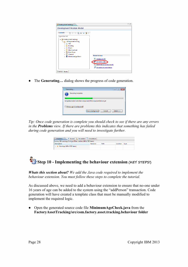
● The Generating… dialog shows the progress of code generation.
Tip: Once code generation is complete you should check to see if there are any errors in the Problems view. If there are problems this indicates that something has failed during code generation and you will need to investigate further.
Step 10 - Implementing the behaviour extension (KEY STEPS!)
Whats this section about? We add the Java code required to implement the behaviour extension. You must follow these steps to complete the tutorial.
As discussed above, we need to add a behaviour extension to ensure that no-one under 16 years of age can be added to the system using the “addPerson” transaction. Code generation will have created a template class that must be manually modified to implement the required logic.
● Open the generated source code file MinimumAgeCheck.java from the FactoryAssetTracking/src/com.factory.asset.tracking.behaviour folder
Page 28 Copyright IBM 2013

Tip: This file contains a blank execute method that will be triggered each time the addPerson transaction is invoked. We will need to add code to this method to make the necessary age checks and reject any transactions where the party is less than 16 years old.
● Replace the MinimumAgeCheck.java file in the workspace with the version supplied with this tutorial.
Tip: This replacement code extracts the root business object from the request (an instance of TCRMPersonBObj) obtains the birth date from it and uses this to evaluate if the person is older than 16 years. If the birth date field is not provided, can’t be parsed, or was less than 16 years ago from the current time an error is reported and the transaction is aborted.
Step 11 - Customizing the Code Table values (KEY STEPS!)
What's this section about? We configure the possible values for the RoomType Code Table. You must follow these steps to complete the tutorial.
As previously discussed, the RoomType provides a mechanism for defining a set of possible room type strings. In this example, we will use the following set of room types:
• Office• PlantRoom• MeetingRoom• StoreRoom
Tip: These String values are NOT stored in the Development model. The generated SQL must be manually modified to add the required values.
Page 29 Copyright IBM 2013

When code is generated for the model, an SQL file named FactoryAssetTracking_CODETABLES_DB2.sql is created in the workspace under FactoryAssetTracking\resources\sql\db2.
This file contains INSERT statements to a add 4 sample values to the CDROOMTP database table as shown below:
This SQL setup file, along with the others in the same folder are combined together to create a single SQL setup file named Setup_DB2.sql in the MDMSharedResources\sql\db2 folder as shown below. This process is dynamic and any changes to the SQL files in the FactoryAssetTracking project are automatically incorporated into the single merged file.
Page 30 Copyright IBM 2013

Tip: The Rollback_... scripts are merged in a similar way into the Rollback_DB2.sql file
Tip: Merged script files are also created for the Oracle and zOS database platforms but they are not used within this tutorial.
Tip: In this case FactoryAssetTracking is the only development project within the workspace. If you create other development projects and generate code, then the SQL files in those projects are also incorporated within the merged master SQL files.
In order that we can modify the values for the Code Table without them being overwritten during code generation we will modify a copy of the master SQL files. You will need to manually maintain this file if further changes are made to the model so that the SQL files in the MDMSharedResources folder are changed.
● Take a copy of the Setup_DB2.sql script from the MDMSharedResourcessql folder and place it into the FactoryAssetTracking\resources folder
Page 31 Copyright IBM 2013

● Open the copied version of the Setup_DB2.sql file, scroll to the end and locate the configuration statements for the Code Table as shown below:
● Replace the name1, name2, name3 and name4 values with the required RoomType values as shown below:
Step 12 - Deploying the code (KEY STEPS!)
What's this section about? - Code developed in the workspace will be deployed to the WebSphere application server. You must follow these steps to complete the tutorial.
Now that the development is complete, the workspace should contain the following projects with code generated ready for deployment:
Page 32 Copyright IBM 2013

The first step is to deploy the Composite Bundle Archive ‘FactoryAssetTracking.cba’ to WebSphere:
● Open the Servers view and locate the target WAS server (eg WebSphere Application Server v8.5 at localhost). Check to see if the server is Started
● If the server is Stopped, start it by opening the context menu on the server definition and selecting the Start option. Wait for the server start-up to complete.
● Open the context menu for the server definition and select Add and Remove…
● In the Add and Remove… dialog select the CBA to be deployed from the Available list and click Add > to move it to the Configured list
Page 33 Copyright IBM 2013

● Click the Finish button to publish the CBA to the server.
● Wait for the Server connection to become Synchronized again
Tip: The CBA is published to the server but not yet associated with a Business Level Application. Before it can be used, it must be configured as a Composition Unit Extension…
● In the Servers view, expand the server connection to reveal the published CBA. Open the context menu for the CBA and select Manage Extensions.
● In the Manage Extensions dialog, expand the Advanced section.
Page 34 Copyright IBM 2013

● Click the Get information from server button to retrieve information about existing deployed applications.
● When the Business-level application dropdown appears, select the target application (in the case of MDM Server this is MDM-operation-server-EBA-E001).
Page 35 Copyright IBM 2013

● When the Composition unit dropdown appears select the target Composition Unit (in the case of MDM Server this is com.ibm.mdm.hub.server.app-E001_0001.eba)
● Click Finish to apply this configuration
Page 36 Copyright IBM 2013

● The Manage Extension dialog will appear whilst this configuration is performed.
● Once the process is complete, check the Server connection status again and wait for it to become Synchronized
Tip: Although the CBA is now fully deployed, the Database configuration must be applied before it can be invoked. The next step is to setup a connection to the MDM database and run an SQL script to apply the necessary configuration.
Step 13 - Deploying the metadata configuration (KEY STEPS!)
What's this section about? - Configuration settings will be deployed to the DB2 database. You must follow these steps to complete the tutorial. ● In the Servers view, open the context menu on the server connection and select
Stop.
Page 37 Copyright IBM 2013

● Wait for the Server connection to become Stopped
● Select the Data Source Explorer view and expand Database Connections ● Open the context menu on the MDM database connection (MDM11DB) and
select Properties
● In the Properties for MDM11DB dialog, Select Driver Properties in the left hand panel, open the General tab in the right hand panel and update the User name and Password fields if necessary. The default values for the MDM Typical Workbench installation are:
DB2 User name : db2adminDB2 Password: db3Admin
Page 38 Copyright IBM 2013

● Click the Test Connection button to determine if these settings are correct. You should see the Success dialog after a few seconds. Click OK to dismiss this window.
● Once you have confirmed the connection to the database is correctly setup, close the Properties for MDM11DB dialog by clicking OK
● Select the Package Explorer view● Locate the Setup_DB2.sql script that you modified in step 11.● Open the context menu over this file and select Open With -> SQL and XQuery
Editor
Page 39 Copyright IBM 2013

● Open the context menu anywhere in the SQL file and select Use Database Connection…
● In the Select Connection Profile dialog, select the MDM11DB database connection and click Finish
Tip: This associates the specific SQL file with the MDM11DB connection. When the script is subsequently executed, this is the database connection that will be used.
● Open the context menu anywhere in the SQL file and select Run SQL
Page 40 Copyright IBM 2013

● The statements in the SQL file will be executed to configure the MDM database. Progress is displayed in the SQL Results view that will open in the workbench.
Tip: You should check to see if the overall process Succeeded or if individual statements failed. Where failures do occur, it may be that a previous deployment is causing conflicts (e.g. a table already exists). You can either resolve such issues by hand or try to remove a previous configuration using the “Rollback” scripts created alongside the Setup script before re-running the setup scripts.
Once the database is configured its time to restart the WAS server:
● Open the Servers view and locate the target WAS server (eg WebSphere Application Server v8.5 at localhost).
Page 41 Copyright IBM 2013

● Open the context menu on the server definition and select Start. Wait for the server start-up to complete
Note: The accompanying document “MDMWorkbenchV11Deployment” provides more detail about the development process including:
• How to remove a CBA from the server• How to export the CBA from the workbench and install this via the
WebSphere admin console.
Step 14 - Testing the Solution (KEY STEPS!)
What's this section about? - Now that the code is deployed and configured this section shows how the services it provides can be invoked and tested.
The code can be tested by running a series of transactions against the server to create and retrieve instances of the Entity Types defined by the model. The transaction documents are supplied in an archived project for your convenience.
● Switch to the Package Explorer view, open the Context menu and select Import…
● In the Import dialog, select General -> Existing Projects into Workspace and click Next
Page 42 Copyright IBM 2013

● In the Import dialog, Select the Select archive file option and click Browse…● In the Select archive containing the projects to import dialog, locate the
supplied SampleTransactions.zip file and click Open
● Ensure the SampleTransactions (SampleTransactions) option is checked and click Finish. This will import the projects containing the sample transactions into the workspace
Page 43 Copyright IBM 2013

TEST 1 - Creating a Site with associated content...
The first XML transaction file we will run is called createTestSite.xml. It will create a new Site instance called “TestSite1”. Contained within the new site will be a single Building instance called “TestBuilding1”. Contained within the new building will be a single Room instance of type PlantRoom called “TestRoom1”. Finally, the Room will have two machine assets listed, TestMachineAsset1 (serial MA0001) and TestMachineAsset2 (serial MA0002). Both of these machine assets are owned by the Person instance created by the MDM Server Installation Verification Test (primary key is 91111111)
Examine the createTestSite.xml document shown below to understand its structure:
Page 44 Copyright IBM 2013

● Again in the Package Explorer view, open the context menu on SampleTransactions -> xml -> createTestSite.xml and select Run as -> MDM Transaction
● In the Edit Configuration dialog, open the Server tab, enable the Use specific server option and select the target WebSphere Application Server.
Page 45 Copyright IBM 2013

● Click Run to execute the transaction
● Progress is displayed in the Console view as shown below. Wait for the Info: Connection successful message to be displayed.
Tip: The first time you run the transaction launcher, it may take longer to complete as client code is loaded and cached. Subsequent transactions will run faster.
Tip: The results of the transaction execution are captured in a file alongside the original request XML file. The file is created on disk and the workspace must be refreshed to detect and show this file.
● Open the context menu on the SampleTransactions project and select Refresh
Page 46 Copyright IBM 2013

● Once the project is refreshed, the XML response file will be visible in a response folder. Open the reponsecreateTestSuite.xml file to see the results.
If the code is working correctly then the response file will contain a SUCCESS result code as shown below. In addition, various fields will be populated with data derived from the server (eg the primary key of the new Site Entity Type)
Page 47 Copyright IBM 2013

SitepkId – Primary key field allocated by MDM Server for the new Site instance. This value can be passed to a subsequent getSite transaction to retrieve the Site instance again.
SiteLastUpdateDate – The date and time of the last update operation (in this case the add operation). This field must be passed to a subsequent updateSite operation to ensure integrity between a getSite and subsequent updateSite. If in independent update occurs between the two transactions then the update will fail as the last update date would no longer be valid.
SiteLastUpdateUser – The user who performed the last update operation
SiteLastUpdateTxID – The transaction id of the last update operation
Test 2 - Creating a new Person Instance With Extended Fields
Next we will test the extended attributes defined by the XPerson Entity Type Extension. The additional field defined by XPerson is ‘HeavyMachineryCertified’ and it applies to instances of Person.
When we invoke an add or an update transaction for Person we include this new field in the request. Since the new field is not part of the underlying Person schema, we include this in an “extended” portion of the request document that all requests support.
The transaction document addPersonWithExtendedField.xml shows how this is done:
Page 48 Copyright IBM 2013

The extended information is stored in the TCRMExtension block (supported by all business objects). We specify the extension object that being provided in the ExtendedObject field and then provide the extension object itself – in this case this XPersonBObjExt.
● Invoke this transaction on the server and check the results as before. You should see a successful invocation of addPerson with populated field values and the TXRMExtension block:
Test 3 - Checking the Behaviour Extension logic is working
● The file addPersonNotSixteenYet.xml contains an addPerson request for someone who is not yet sixteen years old. Try running this transaction and ensure the request is rejected with the following error response:
Page 49 Copyright IBM 2013

Test 4 - Try some other transactions yourself
● Try creating your own transaction requests using the templates under actoryAssetTracking/resources/sampleRequest/
Page 50 Copyright IBM 2013