developing model-based design methods in software engineering
TRANSCRIPT

1
Developing Model-Based Design Methods in Software Engineering
The objective of Chapter 1 is to give an overview of the different model-based design methods in the domain of software engineering and of their development over the past three decades. We have decided to pause for a moment on the most commonly used language for writing models in the domain of system design today: Unified Modeling Language (UML). This standardized language ISO/IEC 19501:2005 [ISO 01] abstractly describes any system whose aim is to be applied via the implementation of a programming language (paying no attention to the specific programming language from the offset, and therefore not restricting itself to the limits of the expressiveness of this programming language). Once the important UML modeling concepts have been presented, the various advantages of this type of approach will be considered: modularity, reusability, portability and so on. In section 1.3.4, we will discuss system validation. Indeed, using design models coupled with formal validation methods for these models is beneficial in terms of speed and strength with regard to the certification of the final system.
1.1. The history of model-based design
From its beginnings in the 1960s, computer program design was unguided and left to the discretion of development teams. This free approach met the design needs of simple programs that had to be run on extremely hard to use hardware systems. Intellectual effort, therefore, principally concerned “how” to make the underlying electronics compute what developers wanted it to calculate. Thus, assembly languages were king.
COPYRIG
HTED M
ATERIAL

2 Rapid Prototyping of Software for Avionics Systems
However, university mathematicians were working on new and complementary approaches that considered real machines indeterminate elements; programs were first and foremost considered abstract, and they were then concretized manually or with tools called assemblers, linkers and compilers. The wide variety of possible uses foreseen for computer-based systems resulted in the development of a large number of programming languages. In 1977, Professor M. Halstead counted some 1,000 different languages [HAL 77] and excluded the countless variations and versions of each of these languages.
Though the object of endless disputes between enthusiasts, these two approaches – university and industry – defended, on the one hand, by mathematicians and, on the other hand, by electronic engineers, have always been complementary. The abstraction of high-level languages has, therefore, democratized these new computer systems whose internal operations are proving to be extremely complex. In return, improvements to electronics have influenced the formalism of languages, their opportunities and performance.
A new scientific era began in the late 1970s: the era of models. In fact, the exponential complexification of computer systems quickly limited humans’ ability to design programs. The introduction of new and more formal methods guiding design enabled these limits to be stretched. Thus, the 1980s saw the appearance (or rather the reappearance and the adaptation) of graphic and text languages. These languages describe systems in a formal way and, instead of being used by machines, coordinate the different participants in application development.
In this new pattern of work, developers together establish a contractual framework for the program, its objectives and the principles of its internal operations. These principles are
Developing Model-Based Design Methods in Software Engineering 3
translated into lines of code in one or several appropriate languages and are finally compiled in a binary form that the machine understands and executes.
Different formalisms have been tested according to needs. Some are adapted to describe the structure of a computer program or of data, others to expose the operation state of the program at a given moment, others still to describe the succession of states through which the program passes or can pass. In the mid-1990s, three major object-oriented design methods were combined under the aegis of the Object Management Group and given the name Unified Modeling Language (UML). The UML is the focus of the following section.
1.2. The Unified Modeling Language, a support for model-based methods
1.2.1. The philosophy and history of the Unified Modeling Language
The principle of using classes and objects rather than functions to model a computer program is relatively old: the programming language Simula [POO 87] introduced this concept to the computer world from 1967. In 1976, the programming language Smalltalk [BRI 96] built on this concept by generalizing its semantics.
However, from 1983, the language C++ [STR 00] – due to its proximity to language C – really democratized this concept. The language C is in fact renowned for programming onboard systems because of its proximity to the hardware. It has, therefore, been widely used and has earned a dominant position in the set of programming languages. The language C++, therefore, appears to be the “natural” successor of the language C in terms of reaching a high level of complexity in computer programs.

4 Rapid Prototyping of Software for Avionics Systems
Similarly, countless design methods have appeared to model computer programs via objects: Booch [BOO 93], Classe-Relation [DES 94], HOOD [ESA 06], Merise [TAR 83], OMT [RUM 90], OOSE [JAC 92], etc. A collective effort for normalization, led by the Object Management Group, resulted in the UML in 1997. In 2000, this norm was accepted by the ISO and was updated in 2005 [ISO 01]. This work combined the three most fashionable methods of the mid-1990s: the Booch, OMT and OOSE methods.
Nevertheless, it is important to point out that UML is a norm that is still subject to certain adjustments. It has been in a constant state of development since its first publication to the present day.
The UML enables computer programs based on the concept of objects to be specified, designed and developed. It formalizes how different artifacts associated with software development are written: scope statements, system and interface requirements, how to split the system into subsystems, the formalization of processes and actors, the structural organization of data, etc.
The principal point of the UML is that it is a consensual (and normalized) language for exchanging information between different entities related to computer software development. However, the UML does not require nor specify any development method or any process to guide developers during the different phases of development.
The UML is designed to communicate through diagrams. These diagrams provide a graphic visualization of the ideas exchanged, facilitating the comprehension of the solution or the solutions proposed. Formalizing diagrams and notations reduces ambiguities, and thus incomprehension, as well as any resulting programming errors. What is more, the UML is independent of any programming language, any

Developing Model-Based Design Methods in Software Engineering 5
process and even any application domain; this helps make it universal.
1.2.2. The Unified Modeling Language normalized diagrams
In its normalized 2.0 version ISO/IEC 19501:2005, the UML defines 13 types of different diagrams that can either be used or not used according to the needs and requirements of software developers. To refresh readers’ memories, a quick overview of some of the most commonly used diagrams will be given below. In fact, countless quality books have provided an exhaustive and detailed description of these diagrams (some of these works are quoted below and are listed in the bibliography).
The first type of diagram to be discussed is the most well-known and the most used: the class diagram (an example of this is given in Figure 1.1). This diagram is a collection of static modeling elements that describe the structure (or the architecture) of a computer program independently from temporal aspects and from the dynamic of the system. The basic element is the class (giving the diagram its name), which is associated with a digital entity and a name. For instance, a class named “Person” can be associated with a set of data describing a person; a class named “Oracle” can be associated with functions generating predictions from parameters, etc. The second basic element in class diagrams is relationships. A relationship associates two classes and can even contain certain properties (noun, cardinality, navigation between the classes, roles of each end of the relationship, etc.). Other elements complete class diagrams: dependency relationships, packages, etc.
Class diagrams are widely used in software development to structure programs, the data they process and associated databases. The design and analysis of class diagrams are the

6 Rapid Prototyping of Software for Avionics Systems
main focus of countless works related to the UML, to the extent that sometimes other types of diagram are eclipsed.
The second diagram is the object diagram. This diagram represents objects, i.e. concrete instances taken from classes at a specific time. This representation gives a more or less precise picture of the state of the object and its relationships with the other objects at a system’s “photography” or “snapshot” moment. It helpfully completes a class diagram showing how the latter can be used. Therefore, the example of a class diagram (Figure 1.1) represents the (simplified) decomposition that was adopted to implement the Secure Next Generation (SNG) router described in Chapter 3. This example can be shown as the object diagrams presented in Figures 1.2 and 1.3, which show two very different configurations of the SNG router deriving from the same software development.
Figure 1.1. Class diagram describing the software structure of the SNG router
Figure 1.2. Example of an object diagram deriving from the previous class diagram

Developing Model-Based Design Methods in Software Engineering 7
Figure 1.3. Another example of an object diagram deriving from the previous class diagram
Figure 1.4. Component diagram for the SNG router
It would have been possible to use another type of diagram to represent the subsystems, the “components”, that constitute the SNG router. The component diagram further explores the structure of a system by emphasizing the “black box” aspect of each subsystem and of the interfaces between the components. This gives the diagram presented in Figure 1.4. Though the UML offers tools that have no effect on the freedom of use, in practice the component diagram is used to obtain a general and undetailed view of the system; the class diagram meanwhile is used to detail each subsystem and each set of data.

8 Rapid Prototyping of Software for Avionics Systems
All of these diagrams are capable of describing a system: from an elevated, abstract point of view down to the smallest details. However, the diagrams are atemporal and do not capture the behavioral aspects of the software system. In the UML, behavioral aspects can be tackled using behavioral diagrams.
The first diagram in this category is the activity diagram. Each activity in this diagram is a sequence of steps. The end of the execution of one activity initiates a transition that leads to the start of the next activity. The activity diagram can include conditions (conditional connection toward an activity or another according to the condition at the moment the transition is made), simultaneously initiate several activities or wait for their conclusion.
Figure 1.5. Activity diagram for partition class Pfr4
Each activity can be described in another activity diagram or using another type of diagram: the State Machine diagram. The latter is the direct descendent of diagrams that explain how finite-state automatons work. The diagram comprises the states and transitions (hence, its name) and describes how a system (objects and components) responds to

Developing Model-Based Design Methods in Software Engineering 9
interactions with its environment by modeling the different states of the system and the transitions between the states.
Figure 1.6. Example of a State Machine diagram derived from Pfr4
Nevertheless, though activity and State Machine diagrams can specify a summarized version of program behavior, acquiring an understanding of the program can require certain logical chains to be extracted that emphasize interactions between entities so that, for example, use cases can be illustrated. The most commonly used diagram for this task is the sequence diagram.
A sequence diagram is comprised of entities (objects or external actors, such as a human operator) that are arranged next to one another. The order in which they are arranged is not significant. Below each entity, there is a vertical line that represents the passing of time. Messages, shown as arrows, then travel from the vertical line of an entity to the vertical line of another entity to indicate that there is a communication between these entities. An example of this is shown in Figure 1.7.

10 Rapid Prototyping of Software for Avionics Systems
Figure 1.7. Sequence diagram, used to test the SNG router
Other types of diagram are specified by the UML norm. Composite structure diagrams show the relationships between components. In this diagram, the components are seen as white boxes. Deployment diagrams can show the physical and geographic arrangement of the entities comprising a complex system. Package diagrams show how entities and their interactions are clustered. Communication or collaboration diagrams are similar to sequence diagrams in terms of content, but they have different semantics: communication diagrams favor exchanging messages between objects, whereas sequence diagrams emphasize chronology. These diagrams, however, have not been used here so, if interested, the readers should consult the bibliography at the end of the book.
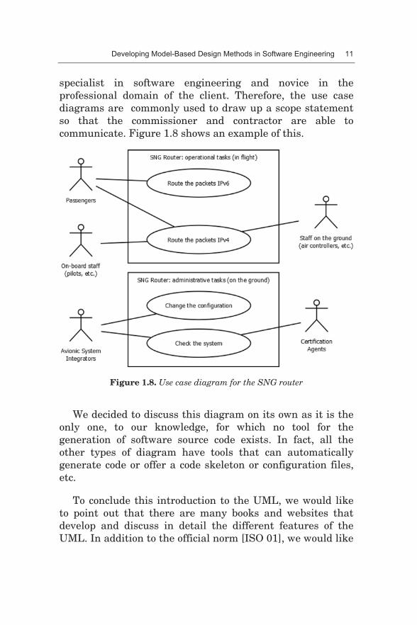
There remains one final type of diagram to be introduced. The use case diagram shows, in a graph, the user actor of a system or a computer program and the actions it can take. The relationships between the actors and actions are then translated into arcs that connect the actor nodes to the action nodes. This diagram is useful as it enables a client, a specialist in their profession and novice in software engineering, to express their requirements to a developer, a
Developing Model-Based Design Methods in Software Engineering 11
specialist in software engineering and novice in the professional domain of the client. Therefore, the use case diagrams are commonly used to draw up a scope statement so that the commissioner and contractor are able to communicate. Figure 1.8 shows an example of this.
Figure 1.8. Use case diagram for the SNG router
We decided to discuss this diagram on its own as it is the only one, to our knowledge, for which no tool for the generation of software source code exists. In fact, all the other types of diagram have tools that can automatically generate code or offer a code skeleton or configuration files, etc.
To conclude this introduction to the UML, we would like to point out that there are many books and websites that develop and discuss in detail the different features of the UML. In addition to the official norm [ISO 01], we would like

12 Rapid Prototyping of Software for Avionics Systems
to point the reader in the direction of the following book by the founders of the UML [JAC 98].
1.2.3. The advantages of model-based design
The decision to fuse object-oriented design methods to form the UML is proof of the maturity of these approaches. Indeed, the concept of objects – tested since the dawn of computer science – has proven effective for managing complex polymorphic software development and is in a perpetual state of development. The classic functional approach (that consists of decomposing a system into functions and subfunctions) has proven to be harder to implement on a large scale and difficult to maintain over the mid and long-term. Therefore, the software industry turned to objects, which are more easily manipulated, maintained and reused over time.
Model-based design has, therefore, become a guarantee of the undeniable levels of effectiveness that are seen today. The UML acts as a support: it provides different views of the system via structural and behavioral diagrams that put the important aspects of the software or the solution to be produced into perspective. Normalized and with clearly specified semantics, the UML enables developers and the users and commissioners of the software to communicate with ease.
Object languages have had decades to become stable, and they are currently widely approved. The aeronautical world, however, remained cautious about object languages that were initially deemed to be too “young” and immature, and therefore potentially too dangerous to use. The qualification

Developing Model-Based Design Methods in Software Engineering 13
of the compilers1, which is practically mandatory at the highest level of software certification, therefore prevented object approaches from entering the world of aeronautical software development. That said, in 2012 the DO-332 [DO 12c], entitled Software Considerations in Airborne Systems and Equipment Certification, was published. This document specifies the certification process for software using object-oriented languages and its application henceforth.
However, communication is not the only use of modeling languages such as the UML. Indeed, its strong semantics enables developers to use models and tools to generate and validate source code. In the 1970s, compilers grew in popularity and quickly became an essential tool in programmers’ toolkits, next to linkers and assemblers. In a similar manner, code generators deriving from UML models or models in other languages are, in turn, growing in popularity and becoming essential.
We will call these code generators “transformers” to differentiate them from the “compilers” that are also generators: compilers generate binary code from the source code in programming languages, such as the language C; transformers generate source code in languages such as the language C from – often graphic – models, such as UML models. As such, the transformer compiler assembler linker chain of tools enables the construction of computer software to be automated.
1.3. Formal model-based validation techniques
Models are able to describe entire software solutions with precision. All or part of the software code can, therefore, be
1 The qualification of a compiler is an optional procedure during the certification of an aeronautical software. The aim of the qualification is to reduce the number of steps involved in the verification of software artifacts.

14 Rapid Prototyping of Software for Avionics Systems
generated in an intermediary language (the language C, C++, Ada, etc.) from these models. Initial models are also precise enough to verify and validate (or invalidate) certain software properties.
Indeed, at an early phase, models are able to verify whether the software or some of its functions could get stuck (no undesirable infinite loop), whether numeric calculations risk failure (the hardware limits of integer coding have not overflowed) and whether some states are specified although they are inaccessible (such states and their associated codes are said to be “dead”).
The methods for verifying these properties in underlying software models can be classified into three categories and will be described below: Model Checking, formal theorem proving and code assertion methods.
Whichever method is used, the verification tool outputs three possible results: a verified-and-validated property, a false property (this result may potentially be accompanied with the counter-example that has invalidated the property) and a neither-validated-nor-invalidated property (when the verification takes too much time or cannot conclude due to insufficient data).
1.3.1. Model Checking
The first of these methods, Model Checking, consists of establishing the set of states through which the program can pass and then browsing this set to validate the property to be verified.
Let us, for example, consider the following algorithm (in the Pascal language) for the retrieval of an integer in a table of two integers between 1 and 3.

Developing Model-Based Design Methods in Software Engineering 15
1 : Function Search_integer (N_to_to_search : 1..4; Tab : array [1.. 2] of 1..3) : boolean ; 2 : Var i : integer; 3 : F : boolean; 4 : Begin 5 : F := FALSE; 6 : If F Then 7 : i := 5; 8 : For i := 1 to 2 do 9 : If Tab[i] = N_to_to_search then 10: F := TRUE; 11: Search_integer := F; 12: End;
Algorithm 1.1. Algorithm for the retrieval of an integer in a table
In this simple example, the Model Checking tool will, in the first step, construct the set of states. At initialization, there are 36 possible states (four possible states for N_to_to_search x 3² for Tab, the states resulting from the initial values of i and F will not be counted in this example). Then the different executions of this function are made in such a way that each of these states is followed by the activation of another state (corresponding to the next instruction) and so on, until the end of the function, as represented in Figure 1.9.
In the second step, the Model Checking tool is, therefore, able to verify that:
– all the initial states lead to the final state and either return as TRUE or FALSE (the algorithm never “gets stuck” in an endless loop);
– F can take no other value than FALSE and TRUE;
– i only takes values 1 and 2, whichever succession of states the function passes through. There is, therefore, never

16 Rapid Prototyping of Software for Avionics Systems
an operation that results in the capacities offered by the integer type being surpassed;
– line 7 is dead code: indeed, branching line 6 never leads to line 7, regardless of the initial state of the function;
– the initial states with N_to_to_search = 4 always lead to the function result being FALSE.
Though simplistic, this function shows the limits of some Model Checking tools. Indeed, an exhaustive analysis of the set of possible states in this function would lead to a combinatorial explosion in cases where the table is larger in size and has “wider” bounds for the data contained in the integer Tab table (Algorithm 1.1). For instance, in a table of 16 cells that each contain a byte, there are 2130 possible initial states (still excluding the states of F and i), therefore, of the order of 1039 states.
Figure 1.9. Partial view of the states of this function

Developing Model-Based Design Methods in Software Engineering 17
However, it is possible for this function to group certain states together. Therefore, if N_to_to_search = 4, then the processing executed on a cell of the integer Tab table is identical for any value other than 4. For the branching of line 9, the cell Tab[i] = 1, = 2, = 3, = 5, = 6, etc. can, therefore, be grouped together.
In the same way, the initial state of F has no importance because at line 5 F is FALSE. Therefore, the Model Checking tool can use a specific value – “whichever” – for F while the state graph for this function is being constructed. The initial state is not duplicated because there is no need to process the initial states F=FALSE and F=TRUE differently. Grouping in this way enables the size of the state graph for function to be drastically reduced and the combinatorial explosion phenomenon to be compensated for.
A good Model Checking tool, therefore, maintains the most reduced space of states possible during construction so that it can verify the properties in a reasonable time. It is worth pointing out that what is understood to be a “reasonable” execution, as a human parameter, varies from one software project to another and in practice can range from seconds to months.
Model Checking tools use the space of states of a function. This space can be represented in a UML state machine diagram. Similarly, some Model Checking tools take a UML state machine diagram as input and directly validate properties on this diagram. Therefore, the state machine model, which is used by developers to design functions and automatically generate part of the software source code, also serves to validate this source code.

18 Rapid Prototyping of Software for Avionics Systems
1.3.2. Formal theorem proving
In addition to Model Checking methods, the academic community has focused on another line of research that seeks to guarantee the properties of software modules. This line consists of extracting a theorem from the module and formally validating this theorem, hence its name “formal theorem proving”.
It is, therefore, possible to extract the following theorem from the function of the previous example: |= (i>0) /\ (i<3). The function and theorem to be proved are given to the verification tool and the tool sends back its results (in this example “validated” because the variable i only concretely takes the values 1 and 2).
Formal theorem proving complements Model Checking: some properties that are unverifiable with one of the methods are sometimes trivial to verify with the other and vice versa.
Internally, formal proving algorithms are often complex algorithms that rewrite the property to show the equivalence of this property joined to the input data with the result.
In the same way that UML state machine diagrams are similar to Model Checking, it is possible to provide UML class diagrams annotated with Object Constraint Language (OCL) and possibly the source code of the property as input for the formal theorem proving tool. The tool then validates or invalidates the property. OCL provides constraint expressions on elements and entities in the diagram. For more information on and quality examples of this language, please consult Chapter 4.
Other formal theorem proving approaches consist of initially writing theorems, abstracts and then successively refining them so that after several iterations the source code

Developing Model-Based Design Methods in Software Engineering 19
is written. This source code is concrete and can be compiled and then executed on a real machine. The formal proving tool, therefore, guarantees the equivalence between the theorem, all successive refinements and the source code. These approaches use text languages such as Coq [BER 14] and B [ABR 96]. Following the publication of DO-333 [DO 12d] in 2012, which relates to the certification of software using formal methods, these formal methods can be used for development in aeronautics. Nevertheless, these approaches differ to those applied to the framework of the SNG router case study that will be presented later. They, therefore, fall beyond the scope of this book.
1.3.3. Code assertion
The third and final category of formal methods that guarantee the aeronautical software is working correctly is code assertion. While Model Checking and theorem proving both chiefly arise from academia, in the 1990s industry was calling on academics for solutions to validate code without the need to rewrite models nor to develop the same piece of software from scratch.
The chosen solution involves adding properties to be validated by directly annotating the software’s source code. These properties are written in the source code comments so that the execution of the compiler remains unchanged. These properties adhere to a specific formalism recognized by the tool that formally validates the properties to be verified. This tool does not modify the code: validations are realized in a static manner without dynamically executing the code on the real system. In terms of terminology, this is the static analysis of the source code.
For commonly verified properties, preconditions, postconditions and invariance clauses are added to the function to be validated, in accordance with Hoare’s 1969

20 Rapid Prototyping of Software for Avionics Systems
logic model [HOA 69]. Preconditions are data that are provided to the verification tool to guide it in its evaluation and inform it of the state of the environment of the function. Likewise, invariance clauses indicate what the function should not modify. Finally, the tool formally verifies that the set of preconditions, invariance clauses and the code of the function to be tested systematically imply the set of postconditions. If this is not the case, the property is invalidated. The tool indicates this to the tester and shows him or her the reasons it failed.
The formalism that is typically used to constrain source code in language C is ACSL [MOY 08 and BAU 09], ANSI/ISO C Specification Language. This formalism can be verified using an automatic tool such as Frama-C [FRA 13]. Internally, this tool exploits a set of modules to realize the abstract interpretation of the code and then formal theorem proving and Model Checking (the last two have been presented in the previous sections).
Code assertion approaches have, therefore, enabled industry to become familiar with formal method concepts and to integrate tools, such as Model Checking and theorem proving codes, more serenely. This approach is an interface somewhere between pure computer science developed in an academic setting and application-based computer science arising from the immediate needs of industry.
1.3.4. Applying for certification for complex systems
Unlike object technologies, which were for a long time officially ignored by aeronautical certification institutions, formal methods were quickly addressed in international certification norms.
Indeed, in 1992 the publication of DO-178B [DO 92] explicitly authorized the use of formal methods. However,

Developing Model-Based Design Methods in Software Engineering 21
the concision of this authorization (just two paragraphs addressed the use of formal methods) raised countless questions about the methods to be implemented and the procedures for validating the use of formal methods for aeronautical software. Industry, therefore, favored other methods, such as exhaustive tests, which were judged more likely to convince certification agents of the innocuity of avionic software.
Consequently, until 2012, certification agents only had a few judicial examples of aeronautical applications validated by formal methods at their disposal. The committee that worked on DO-178C [DO 11], therefore, involved scientific experts in formal methods to expand this point in the new version of the standards. So in 2012, DO-333 [DO 12d] was published, an appendix to DO-178C that relates to the use of formal methods for the certification of aeronautical software.
The use of formal methods offers a myriad of opportunities, ranging from the validation of the software to each stage of its development, primarily the testing phase. Exhaustive tests are always limited by the performance of the computers testing the software and the complexity of the software. Indeed, the latter are becoming increasingly complex because computer systems are calling for ever increasing numbers of functions, there are new interactions between systems that were previously isolated from each other and the quantity and variety of the input data of software is growing.
Whether it is by Model Checking, formal proving or code assertion, formal methods give a formally (and often automatically) verifiable proof. This rapid and synthetic proof replaces “classic” software testing and thereby modifies the workload of testers who are transformed from developers of long tests into developers of short properties to be tested. DO-333 instructs development teams and certification bodies

22 Rapid Prototyping of Software for Avionics Systems
on which manual verification stages can be completed and even entirely replaced by formal automatic methods.
Concretely, the shift from manual tests to automatic tests by formal methods comes back to a shift from manual code to model-generated code. Manually written artifacts (whether they be operational code or tests) must be validated by reviews and/or tools that have themselves been manually validated. Automatically generated artifacts (whether they are code generated from a model or the result of a model-based property validation) are permitted on the condition that the generator has been previously evaluated, i.e. it has been manually reviewed and validated. This intellectual step initially comes with a significant cost, but this is outweighed by additional benefits: reuse and automating the generation of proofs that are provided to aeronautical certification agents.
An original method of software prototyping based on model-based design techniques will be presented in the remainder of this book. The method also uses powerful formal verification methods for the certification of the complex systems produced. A concrete example of an onboard aeronautical system will illustrate how these new techniques enable both the development and validation of the produced system to be accelerated, while sticking to acceptable design and development costs.