developer policy and procedures for water, sewer
TRANSCRIPT

DEVELOPER POLICY AND PROCEDURES FOR
WATER, SEWER, STORMWATER MANAGEMENT, AND STREETS
STANDARDS AND SPECIFICATIONS
TOWN OF WOODSTOCK
DEPARTMENT OF UTILITIES
135 NORTH MAIN STREET
WOODSTOCK, VIRGINIA 22664
Telephone: (540) 459-3621
Fax: (540) 459-3085 Ms. Angela K. Clem M s . M a n d y B e l y e a Town Manager Deputy Town Manager
August 2018 Edition The Design and Construction Standards presented in this manual are the minimum standards to be followed by developers for the Town of Woodstock and are not intended to be used as a substitute for actual construction specifications and design computations.
Disclaimer: It is the responsibility of the purchaser to obtain current information on all VDOT specifications for subdivision street requirements.

i
TOWN OF WOODSTOCK CONSTRUCTION NOTES
THE FOLLOWING CONSTRUCTION NOTES ARE TO BE INCLUDED ON ALL PLANS SUBMITTED TO THE TOWN OF WOODSTOCK:
1. All water and sewer lines shall be constructed according to these plans. All line work shall meet all the requirements of the Town of Woodstock. The property owner is responsible for all water and sewer laterals from the property line to the residence and is the sole owner.
2. The Contractor is responsible for, and shall arrange, all inspections with the Town.
3. The exact locations of all water and sewer service lines on new mains are to be coordinated with the Town’s inspector.
4. All water laterals that cross under a street shall be encased in SCH 40 PVC. The pipe shall be AWWA C904 PEX-a (high pressure peroxide method of crosslinking) with a 200-psi working pressure rating at 73.4 F and extend to the property line.
5. The Town, or authorized agent, shall be responsible for the installation of all water meters. Before installation, the Town requires the following:
- the frame and cover be properly aligned with its meter box and setter - the frame and cover be set to the final grade of the lot - the distance between the top of the cover and the setter shall be between 18” and 21” - the meter box be installed correctly with all components in proper working order, as
required by the Contractor 6. The Town shall supervise the tapping of all existing water lines. The Contractor shall make application and pay for all tapping fees prior to all taps being made.
7. The location of the tap and termination point of the lateral are to be coordinated with the Office of Public Works (OPW). An Application for Services must be made, and all fees must be paid prior to all taps being made.
8. The Contractor shall tie in a new line to an existing manhole by core drilling the manhole.
9. A double check valve backflow assembly is to be installed on any line (fire or domestic) that goes into a building. The assembly is to meet ASSE Standard No. 1015 or 1013. If the assembly is mounted inside a building, a remote readout is required.

ii
TABLE OF CONTENTS Page
TOWN OF WOODSTOCK CONSTRUCTION NOTES i
SECTION 1 - GENERAL TERMS AND REQUIREMENTS 1
1. Interpretation of Terms 2. Procedures for Developer to Obtain Water Service 3. General Charge of Responsibilities 4. Plan Design and Review 5. Approvals and Material Submittals 6. Easements 7. Pump Station Sites 8. Construction on State Highways and Streets 9. Project Acceptance Requirements 10. Dedication of Utilities 11. Warranty
SECTION 2 – WATER 8
A. DESIGN STANDARDS
1. General 2. Hydraulic Design 3. Distribution System Layout Criteria 4. Pipe Size 5. Depth of Bury 6. Service Laterals 7. Meters 8. Backflow Prevention Assemblies 9. Adjacent Utilities 10. Separation of Waterlines and Sanitary Sewers 11. Separation of Waterlines and Storm Sewers 12. Surface Water Crossings 13. Booster Pumping Stations 14. Fire Lines
B. MATERIAL SPECIFICATIONS 13
1. Approved Materials 2. Pipe 3. Fittings 4. Valves 5. Fire Hydrants

333
6. Joint Restraints 7. Valve Boxes 8. Service Laterals 9. Meters 10. Backflow Prevention Assemblies 11. Blow-off Assemblies 12. Couplings 13. Repair Clamps 14. Pipe Casing 15. Pipe Casing Spacers 16. Location Markers
C. CONSTRUCTION STANDARDS 20
1. General 2. Clearing 3. Excavation 4. Sheeting and Bracing 5. Blasting 6. Foundation in Poor Soil 7. Bedding 8. Pipe Line Installation 9. Pipe Restraints and Thrust Blocking 10. Backfilling 11. Valves and Valve Boxes 12. Fire Hydrant Assembly 13. Service Laterals 14. Tapping Existing Mains 15. Blow-off Assemblies 16. Air Release and Vacuum Valves 17. Stream Crossings 18. Meter and Backflow Prevention Vaults 19. Restoration 20. Pressure Testing 21. Disinfection 22. Acceptance of Work
SECTION 3 – SEWER 30
A. DESIGN STANDARDS
1. General 2. Tributary Population 3. Capacity Design 4. Hydraulic Design 5. Collection System Layout

44
6. Location 7. Depth of Bury 8. Adjacent Utilities 9. Separation of Sanitary Sewers and Waterlines 10. Separation of Sanitary Sewers and Storm Sewers 11. Sewage Pumping Stations 12. Force Mains
B. MATERIAL SPECIFICATIONS 36
1. Approved Materials 2. Pipe 3. Manholes 4. Manhole Frames and Covers 5. Fittings 6. Valves 7. Valve Boxes 8. Joint Restraints 9. 4” Gravity Sewer Laterals 10. 2” Force Main Sewer Laterals 11. New Lines into Existing Manholes 12. Metering Stations 13. Cleanouts 14. Blow-off Assemblies 15. Sewage Pumping Stations 16. Repair Clamps 17. Pipe Casing 18. Pipe Casing Spacers 19. Location Markers
C. CONSTRUCTION STANDARDS 43
1 General 2 Clearing 3 Excavation 4 Foundation in Poor Soil 5 Bedding 6 Pipe Line Installation 7 Manholes 8 Backfilling 9 Service Laterals 10 New Line into Existing Manhole 11 New Manhole Over Existing Sewer Line 12 Blow-off Assemblies 13 Air Release and Vacuum Valves 14 Sewage Pumping Stations

5
15 Restoration 16 Stream Crossings 17 Gravity Sewer Line Inspection and Testing 18 Force Main Sewer Line Inspection and Testing 19 Manhole and Pump Station Wet Well Testing 20 Acceptance of Work
SECTION 4 – DRAINAGE MANUAL – TOWN OF WOODSTOCK
SECTION 5 – STREETS
2005 Subdivision Street Requirements Appendix B – Road Design Manual – Subdivision Street Design Guide
SECTION 6 – DETAILS
- 1 - Trench & Bedding - 2 - Restrained Joints (Reducer, Valve, Dead End) - 3 - Restrained Joints (Tee, Cross, Wye, Horizontal Bend) - 4 - Restrained Joints (Vertical Offset) - 5 - Highway Crossing - 6 - Stream Crossing - 7 - 5/8” x ¾”, ¾” and 1” Meter Installation - 8 - 1-1/2” and 2” Meter Installation - 9 - Gate Valve
- 10 - Fire Hydrant Assembly - 11 - Blow-off Assembly - 12 - Water or Sewer Combination Air Release and Vacuum Valve Vault - 13 - Standard Manhole - 14 - Drop Manhole - 15 - Manhole Connection for Pipe Slope (17% or Greater) - 16 - Sewer Lateral for Main with Cover (15 Feet or Less) - 17 - Sewer Lateral for Main with Cover Greater than 15 Feet - 18 - Sewer Cleanout - 19 - Sewer Pump Station – Design Data - 20 - Sewer Pump Station – Typical Wiring Diagrams - 21 - Suction Lift Sewer Pump Station – Section View - 22 - Suction Lift Sewer Pump Station – Plan View - 23 - Suction Lift Sewer Pump Station – Wet Well Cover - 24 - Grinder Sewer Pump Station – Plan View - 25 - Grinder Sewer Pump Station – Section View - 26 - Grinder Sewer Pump Station – Electrical Controls Enclosure - 27 - Concrete Pier and Water/Sewer Crossing Detail - 28 - Thrust Block Detail - 29 - Buttresses for Bends and Tees - 30 - Sewer Pump Station Bypass

- 1 -
SECTION 1 - GENERAL TERMS AND REQUIREMENTS 1 - INTERPRETATION OF TERMS
A. "Town of Woodstock" or “the Town” shall mean the Board of Directors, its employees,
or authorized representatives. The Town of Woodstock shall hereinafter be referred to as the "Town" and be recognized as the policy making body over facilities herein described.
B. "Owner” or “Developer" shall mean any person(s), group, corporation, or affiliations
associated with or responsible for the initiation, design, and/or construction of facilities herein described. These facilities are intended to be under the jurisdiction of, and become a part of, the public utilities system of the Town.
C. "Contractor" shall be any person(s), firm, group, or affiliations charged with the
responsibility of constructing the facilities herein described, and subject to the provisions and regulations set forth herein.
D. "Consultant" or “Engineer” shall mean a professional engineer registered to do business
in the state of Virginia.
E. "Surveyor" shall mean a professional surveyor registered to do business in the state of Virginia.
2 – PROCEDURES FOR DEVELOPER TO OBTAIN WATER SERVICE
A. Developer shall make a written request to the Town for water service availability for a
specific site within the Town of Woodstock. The written request for water availability shall include a detailed description of the proposed land use of the specific site and sketch, map or plat showing the specific site location. All communications and submissions by the Developer and his Engineer shall be with and to the Town.
B. The Town of Woodstock will make a written response to the Developer.
C. Should the Developer desire to pursue the proposed project further, Developer shall
purchase a copy of the Town’s WSS&S. The fee charged for the WSS&S will be the cost of printing and binding the document.
D. Developer shall make a written application for a mainline extension from the Town of
Woodstock. This written application shall include: (a) the legal name and address of the entity to execute the agreement; (b) the name of the proposed subdivision or land development to be covered by the agreement; (c) a site map showing the location of the proposed project; (d) the estimated type and number of units to be served; (e) the estimated average daily water demand for the proposed project and (f) the estimated length by size of water mains to be installed in the project.

- 2 -
E. Developer designs Project and submits construction documents with supporting data to the Town of Woodstock for approval.
F. The Town reviews design of Project and construction documents and approves same for
construction. The Town of Woodstock review comments will be transmitted by facsimile to both the Developer and the Project Designer.
G. Developer secures all needed permits based upon Town approved construction
documents. All permits must be in the possession of the Contractor before construction may begin.
H. Developer furnishes the Town with needed Vendor Certificate of Compliance or shop
drawings, materials billings and materials certifications. Following the notice to construct from the Town, the Developer constructs the project.
I. Following construction, all mainline extensions shall be pressure tested, disinfected and
flushed as stated in these standards and specifications, before connection to the Town’s existing distribution system. Cross-connections in any form are prohibited.
J. Developer shall prepare and deliver the “Record Drawings” to the Town.
K. Developer shall deliver executed copies of all easements of the mainline extension to the
Town.
L. The Town will conduct a review of completed construction, and with all needed documentation in hand, will issue a Certificate of Substantial Completion for the mainline extension.
3 - GENERAL CHARGE OF RESPONSIBILITIES
A. The Town is hereby charged with the responsibilities of inspecting the Contractor’s work
and enforcing these standards and specifications.
B. The Developer is hereby charged with the r e s po ns i b i l i t y of e m pl o yi n g re l i ab l e contractors with sufficient skills and experience to perform all work in an acceptable manner. Failure to do so may result in work stoppage and/or refusal by the Town to accept the project as part of its system.
C. The Contractor is hereby charged with the safe and proper construction of the facilities
herein mentioned. Any dispute resulting from the interpretation of the Town's construction standards and herein described shall be governed by the final decision of the Town.
D. The Consultant is hereby charged with the responsibility for proper design of the
proposed work and submission of the correct number of plans and specifications.

- 3 -
E. The Developer and the Town shall enter into a contract detailing the dedication of the facilities to be constructed according to these standards and specifications. Such contract will be prepared by the Town.
F. After plans and specifications have been approved, the Town reserves the right to make
adjustments in types of materials and methods of construction required, should field inspection reveal unforeseen and/or unfavorable conditions.
G. The Town will supervise all water and sewer laterals that connect to existing lines and tap
all existing water lines. All related costs for this work shall be the responsibility of the Contractor and/or Developer.
H. The Contractor shall contact the Town’s assigned inspector at least 48 hours before
beginning work.
I. It is the Contractor’s responsibility to obtain the required Virginia Department of Transportation (VDOT) permits. No work will be accepted by the Town that has not been accepted by VDOT.
4 – PLAN DESIGN AND REVIEW
A. Any person(s), firm, corporation, or association proposing to construct, expand, or
establish a water or sewer system within the confines of the Town's jurisdictional area shall submit two sets of plans and specifications for review.
B. Drawings, specifications, and engineering reports submitted for approval shall be
prepared by, or under the supervision of, a registered professional engineer, or others legally qualified to practice in Virginia. In addition, all submittals shall include a water model using WaterCAD 7.0, a sewer model using SewerCAD 5.6, and a layout of the subdivision using AutoCAD 2005. The AutoCAD drawing must use the following datum: NAD83 and NAVD88. This will allow for easy coordination and maintenance with the Town’s master map. This submission shall be made in electronic format, i.e., on a readable compact disk. The following layers, at a minimum, shall be submitted on a CD in DWG format, and shall be based on the Town of Woodstock CAD Layer Standards included in the table at the end of this section:
a. Roads (street name) b. Buildings and other structures c. Property Lines d. Sanitary sewers, including:
i. Manholes ii. Gravity sewer lines and force mains
iii. Laterals and cleanouts iv. Valves, plugs, and pump stations
e. Water system details including: i. Water mains

- 4 -
ii. Service lines between the main and the meter iii. Water valves iv. Fire hydrants and hydrant valves v. Water meters
vi. Air release valves vii. Blow-offs and plugs viii. Wells
f. Easements g. Other underground utilities
C. The Town of Woodstock and the Virginia Department of Health (VDH) review and
approval is required of all plans and specifications for water and sewer projects.
D. The Town’s goal is to review the plans within 30 calendar days after receipt
1. In reviewing the application, the Town reserves the right to require such changes, including pipe size, as it may consider necessary to (a) meet the requirements of its standards, and (b) permit future extensions.
2. Any changes will be marked on both sets of submitted drawings and detailed on a
comment sheet. One set will be returned (for correction) to the person or firm submitting the plans. The second set will be retained by the Town. Re-submittal will again require two sets of drawings and a new comment/response sheet.
3. When the plans are approved, they will be so stamped and returned. After
completion of the project, one paper and one mylar set of “as-builts” are required, along with a readable compact disk in AutoCAD release 2005 or earlier. Drawing files on the CD are to be in .PDF format.
E. Plans and specifications are valid for a period of two years from date of approval. If
construction is not in progress at the end of this period, Town approval shall be void. Plans and specifications will then have to be submitted as a new project (if deemed necessary by the Town) and conform to the most current specifications.
F. The plans shall show the following information:
1. Plans shall be drawn on sheets measuring no smaller than 24" wide by 36" long, and
no larger than 30" wide by 42" long.
2. The cover sheet shall contain:
a. Project title b. Vicinity map c. Original seal and the original signature of the registered engineer (following
sheets shall bear the imprint or a legible facsimile of such seal). d. Name, address, and telephone number of the Owner and/or Developer

- 5 -
3. The plans shall show a north arrow, location of existing structures, and proposed or
existing underground utilities, curbs, property lines, railroad crossings, culverts, etc.
4. A general layout sheet shall be provided showing streets, lots, and sanitary sewer and water line locations (both on and off site).
5. Profiles of both water and sewer lines are required.
6. The horizontal scale for profiles shall be the same used for the plan, but in no case,
be smaller than one hundred feet to the inch. The vertical scale shall in no case be smaller than ten feet to the inch.
5 – APPROVALS AND MATERIAL SUBMITTALS
A. All materials used in the construction of water and sewer systems shall have the approval
of the Town. AWWA and ASTM standards are quite broad and may or may not meet the requirements or needs of the Town.
B. Any material not listed in these standards and specifications or not currently accepted by
the Town shall be approved before constructed or installed.
C. The following approval procedure shall be used:
1. A cover letter along with two sets of manufacturer’s certifications, and shop drawings and/or samples shall be sent to the Town’s Director of Public Works.
2. After review, the Director will issue approval or denial of the submitted shop drawing
to the submitter.
D. Unapproved materials placed at a job site shall be subject to immediate rejection and barred from any further consideration.
6 - EASEMENTS
A. Maintenance easements shall be required for all water and sewer lines and appurtenances
except where installed within a public right-of-way of the Virginia Department of Transportation.
B. Maintenance easements shall not be fewer than 20 feet in width and shall be centered on
the main. Combined sewer and water easements shall be 30 feet in width with both mains then ten feet from the edges of the easement. All easements shall have the right of ingress and egress fully provided for in the recorded deed.
C. No building or permanent structure shall be constructed within a maintenance easement
No trees, shrubs, structures, fences, or obstacles shall be placed within an easement

- 6 -
which would render the easement inaccessible by equipment.
D. Where deemed necessary by the Town, easements shall extend to adjacent property for orderly extension of service.
E. Ingress and egress easements shall be required for access to all sewer pump station sites.
The easement shall be a minimum of 12 feet in width. 7 - PUMP STATION SITES
A. The operation and maintenance of all sewer lift pump stations will be private.
8 – CONSTRUCTION ON STATE HIGHWAYS AND STREETS
A. It is the developer’s responsibility to obtain all applicable Virginia Department of
Highway (VDOT) permits. The Town will not accept any work that has not been approved and permitted by VDOT.
9 – PROJECT ACCEPTANCE REQUIREMENTS
A. Substantial Completion will be issued when:
1. All tap and/or service fees have been paid
2. All approved materials have been installed per the Town's requirements
3. The completed work has been inspected and the system is in working order
4. The appropriate tests have been successfully completed (pressure, filtration,
bacteriological, etc.)
5. The sewer mains have been flushed prior to video inspection.
6. The video inspection DVD of the project’s sewer lines has been received and reviewed and pull mandrel to check deflection of the pipeline.
7. The Town has received a copy of the recorded easement and/or pump
station ownership documents with plats that clearly defines that all pump station O/M functions are performed by others.
8. Compact disk of as-built drawings in .pdf format have been received by the Town
9. A substantial completion deficiencies and omissions list has been issued.
B. A project will be accepted for ownership when:
1. The items on the deficiency and omission list have been corrected

- 7 -
2. Any work that was accepted at substantial completion, but later damaged, has been
repaired
3. As-built information has been given to the Town's inspector
4. All fire hydrants have been painted their proper flow rating colors and flow data provided
5. The Town signs the developer’s (1) Affidavit and Waiver of Lien and (2) Bill of Sale.
10 – DEDICATION OF UTILITIES
A. The Owner and Town shall enter into a contract for the dedication of the water and/or
sewer facilities to the Town.
B. Said dedication shall be in writing by:
1. An Affidavit and Waiver of Lien declaring the cost of facilities installed, and
2. A Bill of Sale being duly recorded in the Town of Woodstock Clerk's office. 11 – WARRANTY
A. The Developer will be responsible for any maintenance as a result of construction or
material defects of said facilities for one year from the date of final acceptance. B. The Developer shall post a surety bond for one (1) year with the Town. The developer is
responsible for notifying the Town after one year.

Town of Woodstock CAD Layer Standards
Layer Name
Layer Description
Color
Linotype Bylar
Pen mm
InkJet In.
Plot Color
Microstation Color #
Microstation
Weight C-ANNO Annotation 132 Continuous 0.35 0.014 Black 103 2 C-ANNO-DIMS Dimensions 230 Continuous 0.18 0.007 Black 91 0 C-ANNO-NOTE Notes 132 Continuous 0.35 0.014 Black 103 2 C-ANNO-NPLT Non-plotting graphic information 242 Continuous 0.35 0.014 Red 187 2 C-ANNO-SYMB Reference Symbols 72 Continuous 0.35 0.014 Black 196 2 C-ANNO-TEXT Text 132 Continuous 0.35 0.014 Black 103 2 C-ANNO-TITL Drawing or detail titles 173 Continuous 0.5 0.020 Black 121 3 C-ANNO-TTLB Border and title block Varies Continuous C-ANNO-VPRT View Port 2 Continuous 0.25 0.010 Black 4 1
C-BLDG Building and primary structures 173 Continuous 0.5 0.020 Black 121 3 C-BLDG-TEXT Buildings and primary structures: text 12 Continuous 0.35 0.014 Black 27 2
C-BRDG Bridge 154 Continuous 0.7 0.028 Black 136 5 C-BRDG-TEXT Bridge: text 154 Continuous 0.7 0.028 Black 136 5
C-CATV Cable TV 31 CTV 0.25 0.010 Black 110 1 C-CATV-TEXT Cable TV: text 31 Continuous 0.25 0.010 Black 110 1
C-COMM Communications 31 COMM 0.25 0.010 Black 110 1 C-COMM-TEXT Communications: text 31 COMM-OH 0.25 0.010 Black 110 1
C-DFLD Drain Fields 92 Continuous 0.35 0.014 Black 98 2 C-DFLD-TEXT Drain Fields: text 92 Continuous 0.35 0.014 Black 98 2
C-DRIV Driveways 52 Continuous 0.35 0.014 Black 36 2 C-DRIV-TEXT Driveways: text 51 Continuous 0.25 0.010 Black 28 1
C-ESMT Easements 31 Dashed 0.25 0.010 Black 110 1 C-ESMT-TEXT Easements: text 32 Continuous 0.35 0.014 Black 102 2
C-FENC Fences 132 Varies 0.35 0.014 Black 103 2 C-FENC-TEXT Fences: text 132 Continuous
C-NGAS Natural gas 32 GAS 0.35 0.014 Black 102 2 C-NGAS-TEXT Natural gas: text 32 Continuous
C-POND Ponds 133 Divide 0.5 0.020 Black 111 3 C-POND-TEXT Ponds: text 133 Continuous 0.5 0.020 Black 111 3
C-POWR Power 12 ELEC 0.35 0.014 Black 27 2

C-POWR-TEXT Power: text 12 Continuous 0.35 0.014 Black 27 2 C-POWR-OVHD Power: overhead 12 ELEC-OH 0.35 0.014 Black 27 2 C-POWR-UND Power: underground 12 ELEC-UG 0.35 0.014 Black 27 2
C-PRKG Parking lots 51 Continuous 0.25 0.010 Black 28 1 C-PRKG Parking lot: text 51 Continuous 0.25 0.010 Black 28 1
C-PROP Property 214 Phantom2 0.7 0.028 Black 117 5 C-PROP-TEXT Property: text 212 Continuous 0.35 0.014 Black 101 2
C-PVMT Pavement 51 Continuous 0.25 0.010 Black 28 1 C-PVMT-TEXT Pavement: text 51 Continuous 0.25 0.010 Black 28 1
C-ROAD Roadways 52 Continuous 0.35 0.014 Black 36 2 C-ROAD-CNTR Roadways: centerline 51 Center 0.25 0.010 Black 28 1 C-ROAD-TEXT Roadways: text 51 Continuous 0.25 0.010 Black 28 1
C-SITE Site features 132 Continuous 0.35 0.014 Black 103 2 C-SITE-VEGE Site features: trees, shrubs, and other vegetation 71 Continuous 0.25 0.010 Black 188 1
C-SSWR Sanitary Sewer 73 SSEWER 0.5 0.020 Black 204 3 C-SSWR-TEXT Sanitary Sewer: text 72 Continuous 0.35 0.014 Black 196 2
C-STRM Storm sewer 212 Continuous 0.35 0.014 Black 101 2 CSTRM-TEXT Storm sewer: text 212 Continuous 0.35 0.014 Black 101 2
C-TOPO Topography 73 Continuous 0.5 0.020 Black 204 3 C-TOPO-MAJR Topography: major contours 135 Continuous 1 0.039 Black 127 7 C-TOPO-MINR Topography: minor contours 73 Continuous 0.5 0.020 Black 204 3 C-TOPO-TEXT Topography: text 72 Continuous 0.35 0.014 Black 196 2
C-WATR Water supply system 134 Continuous 0.7 0.028 Black 119 5 C-WATR-4 Water line – 4” or less 1 Continuous 0.18 0.007 Black 3 0 C-WATR-6 Water line – 6” 2 Continuous 0.25 0.010 Black 4 1 C-WATR-8 Water line – 8” 3 Continuous 0.35 0.014 Black 2 2 C-WATR-10 Water line – 10” 4 Continuous 0.35 0.014 Black 7 2 C-WATR-12 Water line – 12” 5 Continuous 0.5 0.020 Black 1 3 C-WATR-16 Water line – 16” or greater 6 Continuous 1 0.039 Black 5 7 C-WATR-HYDR Water supply: Hydrants and connections 133 Continuous 0.5 0.020 Black 111 3 C-WATR-INST Water supply system: instrumentation (meters, valves, etc.) 133 Continuous 0.5 0.020 Black 111 3 C-WATR-PIPE Water supply system: piping 133 Continuous 0.5 0.020 Black 111 3 C-WATR-PROF Water supply system: profile 133 Continuous 0.5 0.020 Black 111 3 C-WATR-STAN Water supply system: stationing 131 Continuous 0.25 0.010 Black 95 1 C-WATR-TEXT Water supply system: text 132 Continuous 0.35 0.014 Black 103 2 C-WATR-WELL Water supply system: well 133 Continuous 0.5 0.020 Black 111 3

- 8 -
SECTION 2 – WATER
A – DESIGN STANDARDS
1 – GENERAL
A. Design standards shall be those set forth in the Bureau of Water Supply Engineering,
Department of Health, Commonwealth of Virginia Waterworks Regulations, Part III, Article 6, except as specified herein.
B. When the Town deems it necessary, it may specify the type of material to be installed
and/or the construction method to be used. 2 – HYDRAULIC DESIGN
A. When water dist r ibut ion system extensions are proposed, the appl icant shal l
f i rs t determine the quantity of water required and then obtain the hydraulic gradient available at the point of connection to the Town's system, which can be obtain from the Town’s Engineer. The engineer shall submit a disk to the Town Engineer containing the following information:
1) a layout of the water system using AutoCAD 2005 2) a model of the proposed subdivision’s water system using WaterCAD 7.0
B. Hydraulic design of piping will be based on pipe carrying capacities consistent with head
losses determined in accordance with the following:
Hazen-Williams Values
Pipe Material Coefficient "C" Ductile Iron (DIP)...............................................120 PVC....................................................................130
Pipe Diameter Coefficient "C"
6".......................................................................100 8"......................................................................110 10".....................................................................115 12" and greater ……………………………....120
3 – DISTRIBUTION SYSTEM LAYOUT CRITERIA
A The distribution system shall be compatible with the Town's plan for an integrated water
system for its service area. The distribution system shall be laid on a loop or grid system. Primary grids shall be of ten inch or larger diameter pipe and shall be spaced at

- 9 -
approximately one- m i l e intervals. Secondary loops of eight-inch diameter pipe will be spaced not more than 1,000 feet apart.
B Dead end mains shall not exceed a length of 500 feet beyond the last service lateral.
C. All dead-end lines shall terminate with a fire hydrant or blow-off assembly. A dead-end
line in a cul-de-sac shall terminate with a fire hydrant assembly. D. A water line that may be extended shall have a gate valve at the end. There shall be one
full length of pipe on each side of the valve. E. Valves shall be located on distribution and transmission mains at intervals not exceeding
1,000 feet. Valves shall be located in distribution systems on all branches (tee, wye, or cross).
F. Combination air release and air/vacuum valves shall be installed at high points where
accumulation of air may interfere with flow. G. Pipeline deflection will only be allowed at joints and at fittings. The length of pipe
itself shall not be bent. The maximum deflection limit shall be 12 inches of lateral displacement per 20 feet of pipe. (If laying radius is 200 feet or greater, no bends are needed.)
H. Distance measurements between fire hydrants shall be along the centerline of roadway
surfaces or along surfaces meeting the requirements of a fire lane (designated or un- designated). In all cases, access to each hydrant shall be directly from a roadway and/or fire lane. Their placement shall be:
1. In areas developed with single or duplex residential units, hydrants shall be located
so the distance from a hydrant to the building set-back line shall be no greater than 400 feet.
2. In areas developed with three to five dwelling units per structure, there shall be a
hydrant within 300 feet of all units.
3. In areas developed with six or more dwelling units per structure, there shall be at least two hydrants within 300 feet of all units.
4. In industrial or commercial developments, there shall be a hydrant within 300 feet of
all portions of any structure. Where one hydrant is dedicated to the operation of a standpipe system there shall be at least one other hydrant meeting the distance requirements set forth above; the hydrant dedicated to the operation of the standpipe system shall not be farther than 50 feet from the standpipe.
I. Wherever possible, a fire hydrant shall be located in the grass strip between the curb and
the sidewalk.

- 10 -
J. Joint restraints are required if the water line slope is 20% or greater, at every valve and
fitting, at all fire hydrants, and at all stream crossings, as required by the Town. 4 – PIPE SIZE
A. The minimum size pipe in residential areas shall be six inches in diameter. The minimum
size pipe in commercial or industrial areas shall be eight inches in diameter.
B. All piping must be capable of providing a minimum flow of two gallons per minute per connection at a minimum of 20 psi residual pressure.
C. Piping shall be sized to provide fire flow of at least 1000 gpm at 20 psi residual
pressure.
D. Piping shall maintain, under all flow conditions (including peak hourly flow plus fire flow), a minimum pressure of 20 psi.
E. Under the following conditions, eight-inch or larger piping shall be used to supply a fire
hydrant:
1. If more than one hydrant is installed on a dead-end main
2. If a hydrant is installed beyond 300 feet of a dead- e n d main (the remaining line beyond the hydrant may be six inches in diameter)
3. If two hydrants are to be supplied on a looped main that contains more than
1,500 feet of pipe
4. If three hydrants are to be supplied on a looped main that has over one 1,000 feet of pipe
5. If four or more hydrants are to be served.
5. DEPTH OF BURY
A. All lines (mains and service laterals) shall be laid with a minimum cover of 42
inches. 6. SERVICE LATERALS
A. Service laterals shall be two-inches or less diameter lines and shall include saddle,
corporation stop, and meter box assembly or vault.

- 11 -
B. Water lateral and meter box assembly or vault shall be placed at the center of the lot wherever possible. The meter box shall be set one foot beyond the property line. In cul-de-sacs, the meter box shall be set adjacent to the adjoining property line.
C. Service for industrial and commercial areas shall be sized to provide the flows
required by the industrial or commercial customer and shall be installed at the time the lot is developed. A gate valve shall be installed within five feet of the building.
7. METERS
A. Both domestic and fire service lines shall be metered.
B. All meters shall have an R-900 RF MIU, or the town’s approved equivalent, encoder register for drive-by reading.
C. The Town shall provide and install meters for service lines of up to two-inch in diameter.
The Contractor shall provide and install meters for service lines above two-inches in diameter and larger.
D. The Contractor shall provide and install all three-inch and larger meters. Wherever
possible, the meter shall be installed at the property line, or as approved by the Town. The Town shall review the appropriate mechanical plan sheets to verify layout and material used.
E. Meter size shall be shown on the plans.
8. BACKFLOW PREVENTION ASSEMBLIES
A. All Service lines (fire and domestic) shall have an A.S.S.E. (American Society of
Sanitary Engineers) approved backflow prevention assembly.
1. The backflow prevention device must be installed immediately after the water meter on domestic and fire service lines.
2. Backflow prevention devices shall be equipped with detector meters. These meters
shall be provided with an encoder register for drive-by reading (see Section 2, Part 2, paragraph 9E).
B. Reduced p r e s s u r e z o n e b a c k f l o w p r e v e n t i o n a s s e m b l i e s s h a l l n o t b e
i n s t a l l e d i n underground vaults. 9. ADJACENT UTILITIES
A. Wherever possible, other utilities shall be placed no closer than five feet horizontally or
eighteen inches vertically (crossings) to a water line. The distances are to be measured inside edge to inside edge.

- 12 -
B. Where water lines and other utilities cross or where terrain features may dictate, the Town reserves the right to have the other utilities properly identified with a marker or other means of identification specifically approved by the Town.
10 – SEPARATION OF WATERLINES AND SANITARY SEWERS
A. The following factors shall be considered in providing adequate separation:
- Materials and types of joints for water and sewer pipes. - Soil Conditions. - Service branch connections into the waterline and sewer pipes. - Compensating variations in the horizontal and vertical separations. - Space for repairs and alterations of water and sewer pipes. - Offsetting of pipes around manholes.
B. Water lines installed parallel to sewer lines shall have at least ten feet of horizontal
separation - edge to edge. Should conditions prevent this separation, the water line shall be ductile iron pipe.
C. Water lines crossing over sewers shall be laid to provide a separation of at least 18 inches
between the bottom of the water line and the top of the sewer. When conditions prevent this vertical separation, the water line shall be of ductile iron pipe.
D. Water lines passing under sewers shall be push-on or mechanical joint ductile iron pipe.
In addition, the water line shall be protected by providing:
1. A vertical separation of at least 18 inches between the bottom of the sewer and the top of the water line.
2. Adequate structural support for the sewers to prevent deflection of the joints (see
Detail 28).
3. The section of water pipe crossing the sewer line shall be centered at the point of crossing so that its ends are equidistant from the sewer.
E. When it is impossible to obtain proper horizontal and vertical separation, both the water
main and sewer shall be constructed of ductile iron pipe. F. No water pipe shall pass through or come into contact with any part of a sewer manhole.
Whenever possible, manholes shall be at least ten feet horizontally from a water main. The distance shall be measured edge-to-edge.
11 – SEPARATION OF WATERLINES AND STORM SEWERS
A. Water lines shall have a minimum separation of 18 inches from storm drainage pipes and
structures.

- 13 -
12 – SURFACE WATER CROSSINGS
Surface water crossings present special problems and should be discussed with the Town before final plans are prepared. The following is to be used as guidance for surface water crossings:
A. All surface water crossings shall be under water. There will be no above water crossings
allowed by the Town of Woodstock. B. Pipes shall be of special construction with flexible watertight joints.
C. Valves shall be provided at both ends of the water crossing so that the section of pipe can
be isolated for repairs or testing. All valves shall be easily accessible and not subject to flooding.
D. Permanent taps shall be made for testing and for locating leaks.
13 – BOOSTER PUMPING STATIONS
A. All proposed booster pumping stations shall be submitted to the Town Engineer for
review. The pumping station is to be included in the WaterCAD model submittal, as stated in Section 1-4 of these Standards.
14 – FIRE LINES
A. All water lines serving a fire suppression system in a building shall be shown on the
drawings. B. All fire lines shall be owned and maintained by the property owner.
C. A valve shall be located on the fore line at the point it connects to the public water
system. D. The minimum size fire line shall be 3-inch ductile iron pipe (DIP).
B – MATERIAL SPECIFICATIONS
1 – APPROVED MATERIALS
A. All materials used in the construction of the water system shall have the approval of the
Town. AWWA and ASTM set forth only a set of standards for materials. Since these standards are quite broad, they may or may not meet the requirements or needs of the Town.

- 14 -
B. Any materials not listed in these standards and specifications or not currently accepted by the Town shall be approved by the Town before installation.
C. The following approval procedure shall be used:
1. A cover letter along with two sets of manufacturer's certifications, and shop drawings
and/or samples shall be sent to the Town.
2. After review, the Town will issue a letter stating whether the product is acceptable or
not. D. Unapproved materials placed on a job site shall be subject to immediate rejection and
barred from any further consideration. 2 – PIPE
A. Polyvinyl chloride pipe (PVC) shall meet the requirements of (1) NSF Standard 60/61 or
ASTM D2241 for pipe, (2) ASTM D3139 for push-on joints, and (3) ASTM F477 for gaskets. The PVC compounds must conform with material code PVC 1120 of ASTM resin specification D1784. The pipe shall have a minimum wall thickness of SDR-21 for normal applications. Pipe shall be C-900 DR14 at 200 psi or C-909 200 psi. Pipe shall be manufactured by ETI, CertainTeed, Johns-Manville or our approved equal.
B. Ductile iron pipe shall conform to the requirements of AWWA Standard C151. The pipe
shall be cement lined in accordance with AWWA Standard C104. Unless otherwise specified, the pipe shall have push-on joints meeting the requirements of AWWA Standard C111. The wall thickness of the pipe shall be Class 52. Pipe shall be manufactured by Griffin Pipe Co., Clow Corporation, or approved equal.
3 – FITTINGS
A. All fittings shall be Class 350 ductile iron. Ductile iron shall conform to ASTM A536-72,
minimum grade 70-50-05. Nominal thicknesses of fittings shall be equal to, or exceed, Class 54 ductile iron pipe thicknesses. Radii of curvatures shall conform to AWWA C153-00. Fittings shall be cement lined in accordance with AWWA C104-74. Joints shall conform with the requirements of AWWA Standard C111 and shall be compatible with the type of pipe used. Fittings shall be manufactured by Griffin Pipe Co., Tyler Pipe, or approved equal of United States/domestic manufacture only.
B. All fittings for pipe six inches or greater in diameter shall be mechanical joint if used in a
buried installation. Fittings shall be flanged if installed above ground or in a vault. C. Fittings for pipe two inches and smaller are covered under Paragraph 8 (Service
Laterals).

- 15 -
4 - VALVES A. All valves less than twelve (12) inches shall be resilient seat gate valves and
conform to the specifications set forth in AWWA Standard C509 or C515. Valves will have a double O-ring stem seal, a minimum stem diameter of 7/8 inch, and will open left (counter-clockwise). Valves shall be designed for working pressure not less than that specified for the connecting pipe. Gate valves shall be manufactured by Mueller, American Flow Control 2500 Series, or approved equal by the Town.
B. Valves for above ground mounting or installed in vaults shall have an outside screw and
yoke and flanged ends. Valves for buried installation shall have a 2-inch square operating nut, (OPEN LEFT) non-rising stem, and mechanical joint confirming with AWWA Standard C111, unless otherwise specified.
C. Combination air release and air/vacuum valves will have cast iron bodies with stainless
steel floats. Other internal parts will be either stainless steel or bronze. Valves will be sized appropriately for each application. Valves shall be Val-Matic Model No. 201C for six-inch through ten-inch lines, or 202C for 12-inch and greater lines, or our approved equal.
D. Special valves such as pressure reducing, altitude, etc., shall be manufactured by Cla-Val
Company, Golden Anderson, or approved equal by the Town. E. Ball valve curb stops shall meet AWWA Standard C800-84. They shall have tee head
checks in the body that permit a 90 degree turn only.
1. One-inch ball valve curb stops shall have pack joint ends. They shall be Ford catalog number B44-444, or our approved equal.
2. Two-inch ball valve curb stops shall have female iron pipe threads on both
ends. They shall be Ford catalog number B11-777 or our approved equal. F. Angle valves shall be straight 5/8” size and shall be Ford BA 94-313W or our approved
equal.

- 16 -
5 - FIRE HYDRANTS
A. Hydrants shall conform with the specifications in AWWA Standard C502 for dry-barrel
fire hydrants. Hydrants shall be compression type, with six-inch mechanical joint inlet and minimum bury of 4.5 feet. Unless otherwise specified, hydrants shall be traffic model with a 5 ¼” valve opening, one 4 1/2" pumper nozzle, and two 2 1/2" hose nozzles. All nozzle threads shall be national standard. The operating nut shall be pentagon in shape, 1 1/2" point to flat, non-rising and open left (counter-clockwise). Hydrants shall have a finish coat of red paint applied by the manufacturer. Hydrants shall be Mueller 5 ¼” Super Centurion 250 Model A-423 (open left).
6 - JOINT RESTRAINTS
A. Glands to restrain MJ fittings and pipe bells to DI pipe shall be EBAA Iron megalug
series 1000, Ford uni-flange series 1400 DA, or our approved equal.
B. Glands to restrain MJ fittings and pipe bells to PVC pipe shall be EBAA Iron megalug series 2000PV, Ford uni-flange series 1500, or our approved equal.
C. Glands to restrain PVC pipe bell to spigot shall be EBAA Iron megalug series 6500, Ford
uni-flange series 1390, or our approved equal.
D. Glands to restrain DI push joint pipe bell to spigot shall be Field Lok 350 Gaskets, EBBA Iron Megalug Series 1700, Ford Uni-flange Series 1450, or our approved equal.
7 - VALVE BOXES
A. Valve boxes for gate valves shall be two-piece cast iron with a 7 3/8" drop lid marked
“water”. Boxes shall be screw type adjustable with a 5 1/4" shaft diameter. Adjustment range shall be one foot. The box length shall be determined by depth of bury. The valve box shall be a Tyler 6850 Series, item number 564-S, or East Jordan Iron Works, or our approved equal.
B. Roadway boxes shall be used with ball valve curb stops. They shall have a 5 ¼” shaft
with a 5 ¼” drop lid. The box length shall be determined by depth of bury. The roadway boxes shall be East Jordan Ironworks, 8500 Series, or Tyler Series, or our approved equal.
8 - SERVICE LATERALS
A. Service saddles shall be Ford style FS202 or our approved equal.
B. Corporation stops shall have an inlet threaded in accordance with AWWA Standard
C800 and a pack joint outlet. They shall be Ford series FB1000 or our approved equal.
C. Pipe for service laterals shall be AWWA C904 approved PEX-a (high pressure peroxide method of crosslinking) with a 200-psi working pressure rating. Pipe shall be certified to standards ASTM F876, NSF 14 and NSF 61 with a material designation code of “3306”.

- 17 -
A co-extruded, blue-colored ultraviolet (UV) shield shall be on the exterior. Pipe shall have a minimum recommended UV exposure time of one (1) year when tested in accordance with ASTM F2657. Manufacturer shall issue a minimum of one (1) year warranty for UV protection, and a twenty-five (25) year warranty for the performance of the pipe. Product shall be REHAU MINICIPEX.

- 18 -
D. Fittings for one-inch or two-inch diameter service laterals shall be pack joint or threaded NIP. The fittings shall be manufactured from AWWA Standard C800 and be red brass of 85,5,5,5 alloy.
E. No meters set ter for 1-inch meters . All meters up to 1 inch shall be yoke only.
F. Copper setters for two-inch service lines shall be Ford Copper setter, Catalog
No. VBHH77-15BHC-11-77 or our approved equal. G. Meter box assemblies for 5/8" meters: (see Drawing 7)
1. The meter box shall be polyethylene plastic with a minimum wall thickness of one-
half inch. The box shall be 18 X 22 X 30. Its vertical crush strength shall be a minimum of 20,000 pounds.
2. In non-traffic areas, the box cover shall be a C52 by Ford, E-Coated with a Ford 501
Yoke Bar, E-Coated.
3. In traffic areas, the box cover shall be a Ford A32HH-T or our approved equal.
H. Meter box assemblies for 1" meters: (see Drawing 7)
1. The meter box shall be polyethylene plastic with a minimum wall thickness of one- half inch. The box shall be 20 X 24 X 30. Its vertical crush strength shall be a minimum of 20,000 pounds.
2. In non-traffic areas, the box cover shall be a Ford C-53 or our approved equal.
3. In traffic areas, the box cover shall be a Ford MC-30 (frame) with an RML-12-T
top lid or our approved equal. I. Meter vault assemblies for two-inch service laterals: (see Drawing 8)

- 19 -
1. The meter vault shall be a three-foot riser section of a four-foot diameter manhole. It shall have two cutouts 180Ε apart for the water line to pass through. Each cutout shall be eight inches tall and six inches wide.
2. The riser section shall be covered by a standard manhole flat top with a cast-in-place
access door. In non-traffic areas, the door shall be 30" x 30" and be a Halliday Products model S1R3030 or our approved equal. In traffic areas, the door shall be 24" x 24" and be a Halliday model H1R2424 or our approved equal.
3. The door shall have a 1 3/4" hole to accept the Town’s meter interface unit.
9 - METERS
A. All water services, domestic and fire, shall be metered.
B. The Town shall provide and install all domestic meters for 1-inch and 2-inch service
lines. The meter shall be Neptune with an encoder register and a R900 meter interface unit (MIU).
C. Meters for lines 2 inches and larger shall be provided and installed by the Contractor. The
Town will decide the Model number upon application.
1. Turbine meters shall have a strainer. D. Fire service meters shall be provided and installed by the Contractor. The town will decide model number upon application.
E. All meters shall have encoder type register for automatic meter reading and shall conform
to the following:
1. Encoder system shall include the meter, encoder register, and meter interface unit for remote data collection.
2. Encoder shall be absolute type; capable of reading the position of each number/wheel.
(Pulse type encoders and battery powered units are not permitted).
3. Encoder registers shall be hermetically sealed.
4. Meters shall read in U.S. gallons. 10 - BACKFLOW PREVENTION ASSEMBLIES
A. Each metered service connection (and its bypass, if applicable) must have an A.S.S.E.
(American Society of Sanitary Engineers) approved backflow prevention device installed. The Town must approve the type of device submitted based on the degree of hazard of the planned use.

- 20 -
1. Metered service lines with a low degree of hazard must be provided with a double-
check valve backflow prevention assembly that is tagged, stamped, or embossed to indicate it does meet A.S.S.E. Standard No. 1015. The assembly shall be a Watts Model 709 or Model 774, or our approved equal.
2. Metered service lines with a high degree of hazard must be provided with a reduced
pressure zone backflow prevention assembly that is tagged, stamped, or embossed to indicate it does meet A.S.S.E. standard No. 1013. The assembly shall be a Watts Model 909 or Model 994, or our approved equal.
B. Each fire line service connection (and its bypass, if applicable) must have an A.S.S.E.
approved backflow prevention device installed. The Town must approve the type of device submitted based on degree of hazard of the planned fire service.
1. Fire lines with a low degree of hazard (no additives or antifreeze) must be provided
with a detector double check backflow prevention assembly with A.S.S.E. Standard No. 1048 identification made part of the device. The assembly shall be a Watts Model 774 DCDA or Model 774 XDCA, or our approved equal.
2. Fire lines with a high degree of hazard (additives or antifreeze) must be provided with
a reduced pressure detector assembly with A.S.S.E. Standard No. 1047 identification made part of the device. The assembly shall be a Watts Model 909RPDA or Model 995 DCDA, or our approved equal.
C. All detector (metered) assemblies mounted inside of structures are required to have an
encoder type register for automatic meter reading. Refer to paragraph 9 for meter requirements. The readout shall be mounted on the outside of the structure at a height and location approved by the Town.
11 - BLOW-OFF ASSEMBLIES
A. See Drawing 11 for materials required.
12 - COUPLINGS
A. Couplings for pipe six-inch or greater in diameter shall be mechanical joint, long length,
solid sleeve. 13 - REPAIR CLAMPS
A. Repair clamps shall be full circle all stainless-steel band as manufactured by Ford, style
FS1, (2" through 12"), and style FS3 (14" through 24"). Clamps for pipe sizes two-inch through eight-inch diameter shall have a minimum length of 15 inches. Clamps for pipe sizes ten-inch through 12-inch diameter shall have a minimum length of 20 inches. Larger pipe sizes require 24-inch length.

- 21 -
14 - PIPE CASING
A. Casing pipe for water mains shall be sized in accordance with Drawing 5. Casing pipe
shall be steel and shall meet ASTM specifications A252 Grade 2, or 139 Grade B. B. Casing pipe for water service laterals shall be PVC and may be SDR21 or SCH40.
1. For 1" diameter piping, the casing shall be 3" diameter.
2. For 2" diameter piping, the casing shall be 6" diameter.
15 - PIPELINE CASING SPACERS
A. Separation of carrier pipe from casing pipe shall be by manufactured steel and/or plastic
casing spacers. Spacers shall be by PSI, Inc., Recon, or our approved equal. 16 - LOCATION MARKERS
A. Water location markers shall be EMS 1403 Water XR 12-gauge wire suitable for direct bury to extend to the meter box and valve boxes and have non-detectable tape 6 inches wide placed 12-18 inches above pipe line.
C – CONSTRUCTION STANDARDS
1 - GENERAL
A. All construction shall be in strict accordance with approved plans and specifications. Any
deviations or changes shall be submitted to the Town for supplemental approval. B. The Town shall have the required number of plans before construction begins.
C. The Town shall have access to the construction work at any time for inspection of work
and construction methods. D. All valves, hydrants, and blow-offs shall be operated with proper wrenches in the presence
of Town personnel, except in the case of an emergency. E. Upon acceptance and expiration of warranty, the Town will assume responsibility for
locating water and sewer lines in response to Miss Utility location requests after bond release.
F. The installation of new services on existing lines shall be supervised by the Town at time
of utility construction. Application for, and installation of the service, shall be early in the project to ensure the work is completed in a cost efficient and timely manner.

- 22 -
G. All pavements or roadways that are cut while installing piping, valves, valve boxes, or appurtenances shall be repaired promptly within ten (10) working days.
2 - CLEARING
A. The right-of-way shall be cleared of all trees, stumps, shrubs, and other foreign matter for
a minimum distance of ten feet from each side of the center line of the mains being constructed. The debris shall be disposed of in an acceptable manner. No debris shall be buried within the right-of-way.
3 - EXCAVATION
A. Minimum clearance between the side of the trench and pipe shall be eight inches. The
width of the trench above the top of the pipe may be as wide as necessary for sheeting or bracing and the proper performance of the work. All trench walls should be kept as vertical as possible and still meet OSHA requirements. The trench shall be excavated to a uniform subgrade as required for installation of pipe bedding material.
B. Excavation at manholes and similar structures shall be sufficient to leave at least 12
inches between the structure's outer surface and the embankment or sheeting. C. Excavated material suitable for backfilling shall be piled in an orderly manner and be a
minimum distance of three feet from the bank of the trench. All excavated material not suitable and/or not required for backfill shall be removed and disposed of in an approved manner.
D. Such grading as necessary shall be done to prevent water from flowing into the trench or
other excavations, and any water accumulating therein shall be removed by approved methods.
E. All fill material shall be in place and compacted before sewer lines are installed.
4 – SHEETING AND BRACING
A. Excavations when needed shal l be protected by furnishing and instal l ing
shoring materials that shall be in full compliance with Federal, State and Local laws, rules and regulations.
B. Failure of the Town of Woodstock to suggest the use of shoring, sheeting or piles for
support of sheeting shall not relieve the Contractor of any responsibility for the condition of the excavation at any site.

- 23 -
5 - BLASTING A. The Contractor shall be solely responsible for destruction of property or injury of persons
as a result of the use of explosives. Blasting shall only be utilized in full compliance with Federal, State, or Local laws and regulations.
B. A licensed, competent blaster shall supervise all blasting operations.
6 – FOUNDATION IN POOR SOIL
A. Whenever the soil at the trench sub-grade elevation is soft, unstable, or saturated with
water, such unsuitable material will be removed and trench sub-grade stabilized with a granular stabilization material.
B. Maximum size of granular material shall be two (2) inches.
C. Depth of stabilization shall be as required to construct a firm sub-grade for pipe bedding
material. D. Concrete cradles shall be provided when necessary to bridge highly unstable soils.
7 - BEDDING
A. Refer to Drawing 1 for types of bedding.
B. Bedding material shall be an open-graded coarse stone aggregate meeting Virginia
Department of Transportation's requirements for size number 68, 78, or 8. C. Standard bedding shall be used unless poor soil conditions are encountered. In this type
bedding, there shall be a minimum of six inches of stone under the pipe. Stone shall also be backfilled around the pipe and to a height of six inches above the top of the pipe. This type of bedding shall also be used with sewer laterals.
D. Holes shall be scooped out where joints occur leaving the entire barrel of the pipe bearing
on the bedding. 8 - PIPE LINE INSTALLATION
A. Force main center line shall be staked at 100-foot intervals and at all bends.
B. After bedding has been installed, pipe and fittings shall be laid in accordance with the
manufacturer's instructions and recommendations. Damaged or unsound material will be rejected.

- 24 -
C. Before installation of pipeline, attach 12-gauge insulated wire to the bottom of each pipe section with tape.
D. Pipeline deflection of force main lines will only be allowed at joints and at fittings. The
length of pipe itself shall not be bent. The maximum deflection limit shall be 12 inches of lateral displacement per 20 feet of pipe.
E. Force main fittings shall be restrained per the requirements of Drawings 2, 3, and 4.
F. On force main sewer, location markers (buried transponders) shall be placed:
1. At 50-foot intervals
2. At each bend
3. At the end of each joint that is deflected, and
4. At any additional location the Town's engineer shall direct. G. At the completion of the work shift, the end of the installed pipe will be sufficiently
plugged to keep out trench waters, soil, and other extraneous material. H. See Drawing 5 for requirements in making a typical highway crossing.
9 – PIPE RESTRAINTS AND THRUST BLOCKING
A. Pipe restraints shall be constructed as per manufacturer’s recommendation.
B. For concrete thrust blocking, refer to details 28 and 29 at the end of these standards.
10 - BACKFILLING
A. The Town's specified stone aggregate shall be used to a height of six inches above the top
of the pipe. B. Above the stone aggregate (or concrete arch) shall be 24 inches of select backfill compacted
in six-inch lifts. The maximum particle size of this backfill material shall be one-inch. Backfill shall be compacted to 95% of ASTM 698 maximum density.
C. Above the select backfill, material shall be deposited in lifts not exceeding two feet.
D. Any backfill material used above the pipe bedding shall be free of all organic material,
large clods, frozen soil, or other materials difficult to compact. E. No rock shall be used in the select backfill. Any rock used above the select backfill shall
be no longer than five inches in the greatest dimension.

- 25 -
11 – VALVES AND VALVE BOXES
A. Valves shall be installed as shown on Drawing 9.
B. Both sides of a valve shall be restrained.
C. Valves 12 inches and larger shall have an 8" x 8" x 16" solid block under them. D. The valve box shall be placed directly over and centered on the valve with the bottom
of the box set at or below the top plate of the valve. The valve box shall be set plumb. The backfill shall be carefully tamped to the surface.
E. Valves set over five feet in the ground shall have extension rods added to bring the
operating nut to within two feet of the surface. F. All pavement and roadways material that are cut while installing valves or boxes shall be
repaired promptly within ten (10) working days. G. Valve boxes shall be protected by a skid pad of concrete or asphalt one-foot six-inches in
diameter by six-inches thick. 12 – FIRE HYDRANT ASSEMBLY
A. Hydrant assembly (hydrant and its gate valve) shall be installed as shown on Drawing 10.
B. Before installing a hydrant, care shall be taken to see that all foreign material is removed
from the interior of the barrel. C. Both hydrant and its valve shall be restrained.
D. The area around hydrants shall be backfilled with stone to a minimum height of six
inches above the top of the base. All backfill around hydrants shall be thoroughly compacted to the surface.
E. The area of hydrant placement shall be free of all obstructions in front of and within three
feet of all sides. F. The pumper nozzle shall face the means of access.
G. Hydrants shall have one finish coat of paint applied after installation. Paint shall be
"Chinese Red" as manufactured by Duron. H. The bonnet and three nozzle caps shall be painted the appropriate flow rating color:
black: 249 gpm and below

- 26 -
red: 250 gpm through 500 gpm orange: 501 gpm through 999 gpm green: 1000 gpm through 1499 gpm blue: 1500 gpm and above
Project inspector shall designate the color.
13 – SERVICE LATERALS
A. Wherever possible, the lateral shall be placed at the center of the lot with the meter box
set one foot beyond the property line or far edge of sidewalk. A horizontal separation of 10-ft should be achieved between water and sewer laterals, with the water lateral placed upstream of the sewer lateral.
B. Laterals shall be installed as shown on Drawings 7 and 8.
C. The exact location of water services on new lines is to be coordinated with the Town's
inspector. D. Service laterals connecting to existing lines shall be installed by the Town. The location
of the tap and the placement of the meter box (vault) are to be coordinated with the town’s engineering assistant.
E. A saddle will be required for all taps into PVC pipe. A saddle will be required for all taps
up to 2-inches. F. Proper tapping machine and coupon extractor shall be used.
G. Service laterals shall be installed with a minimum of 48 inches of cover over the top of
the pipe. There shall be six inches of stone under the pipe and meter box and six inches of stone over the top of the pipe.
H. Meter boxes shall be encircled with three inches of stone. The stone shall be placed to the
top of the box. I. Laterals will be continuous (without joints) from the corporation stop to the angle ball
inlet valve. A two-foot tail piece shall be installed beyond the meter box. The end shall have a coupling and plastic plug to prevent intrusion of foreign matter.
J. Care shall be taken in compacting trenches to prevent damage to the pipe and strain on
the meter copper setter. Pipe which is damaged so as to cause a restriction in flow shall be replaced.
K. The end of the lateral shall be marked with a treated 2 x 4 extending from the tail piece to
18 inches above the ground. The top six inches of the 2 x 4 shall be painted blue.

- 27 -
L. Before a permanent meter is set:
1. The frame and cover must be properly aligned with its meter box and copper setter.
2. The frame and cover must be set to the final grade of the lot.
3. The distance between the top of the cover and the copper setter must be between 18 and 21 inches.
4. All components of the meter-box assembly must be in proper working order.
It is the Contractor’s responsibility to have the meter box assembly installed correctly.
14 – TAPPING EXISTING MAINS
A. Connections to existing water mains shall be supervised by the Town or its agent. The
contractor/developer will furnish the material and make the tap. The location of the wet tap shall be coordinated with the Town’s engineering assistant. The Contractor shall make application for and pay the cost of the work. Should water service be disrupted, the Contractor has the responsibility of notifying those customers whose service will be affected.
15 – BLOW-OFF ASSEMBLIES
A. Blow-off assemblies shall be installed as shown on Drawing 11. They shall be set within
one foot of the property line. 16 – AIR RELEASE AND VACUUM VALVES
A. Valves shall be installed as shown on Drawing 12.
17 – STREAM CROSSINGS
A. Stream crossings shall be installed as shown on Drawing 6. Pipe shall be ductile iron
from within twenty feet of each side of the top of stream bank. The pipe under the stream bed shall be encased in concrete. Contractor will perform the work in a manner which will minimize erosion and blocking of the watercourse.
18 – METER AND BACKFLOW PREVENTION VAULTS
A. Meters three inch and larger and their backflow prevention assemblies shall be installed
outside the building wherever possible. Backflow prevention devices shall be tested yearly at the expense of the owner and the town provided a copy of the testing/repair results.

- 28 -
B. Meters shall have an encoder register for drive-by meter reading (see Section 2, Part 2, paragraph 9 E).
19 – RESTORATION
A. Areas that are disturbed during construction shall be returned to conditions at least equal
to that which existed prior to the start of work. The ground is to be returned to the same contour as existed before construction. Trees, shrubs, etc., in easements are not to be replaced. Disturbed earth surfaces shall be left with ground cover similar to surroundings. Restoration shall commence immediately following the completion of work on any section or division of a project.
20 – PRESSURE TESTING
A. Service laterals are to be installed before testing.
B. Lines shall be tested through the outlet angle check valve of a service connection or a
special tap installed for the test. C. A maximum of one thousand linear feet of line shall be tested at a time. D. Tests must be conducted in the presence of a Sanitation Town inspector.
E. All water pipe shall pass a hydrostatic pressure test.
1. All newly laid pipe, or any valve section thereof, shall be subjected to a hydrostatic
pressure of at least 1.5 times the working pressure at the point of testing.
2. Test pressures shall:
a. Be a minimum of 175 psi b. Not exceed pipe design pressure c. Be of at least a two-hour duration d. Not exceed the rated pressure of the valve
2. Each valve section of pipe shall be slowly filled with water. The specified test
pressure shall then be applied by means of a pump connected to the pipe. The manner of connecting the pump to the piping shall be satisfactory to the Town. The water and container used to pump up the line to be tested shall be properly disinfected.
4. Before applying the specified test pressure, air shall be expelled completely from the
pipe, valves, and hydrants.
5. All exposed pipe, fittings, valves, hydrants, and joints shall be examined carefully during the test. Any damaged or defective pipe, fittings, valves, or hydrants that are

- 29 -
discovered following the pressure test shall be repaired or replaced with sound material. The test shall be repeated until it is satisfactory to the Town.
6. Leakage shall be defined as the quantity of water that must be supplied into the newly
laid pipe, or any valve section thereof, to maintain pressure within five psi of the specified test pressure after the air in the pipeline has been expelled and the pipe has been filled with water.
7. There shall be zero leakage during the two-hour test period.
21 – DISINFECTION
A. Disinfection testing shall be performed after the pressure testing has been completed.
B. All pipe and equipment shall be disinfected by the continuous feed method or the tablet
method in accordance with AWWA C-651-86 or current revision.
1. Continuous Feed Method: Potable water shall be introduced into the pipe line at a constant flow rate. Chlorine shall be added at a constant rate to this flow so that the chlorine concentration in the water in the pipe is at least 50 mg/l. The chlorinated water shall remain in the pipe at least 24 hours, after which its chlorine concentration shall be at least 10 mg/l.
Grams of HTH Powder Required for Dose of 50 mg/l*
Length of Section Diameter of Pipe In Feet In Inches
_2_ 6 8 10 12 13 . . . . . . . . . . . . . . . . . . . 0.6 5.56 9.88 15.45 22.24 18 . . . . . . . . . . . . . . . . . . 0.85 7.69 13.69 21.39 30.80 20 . . . . . . . . . . . . . . . . . . 0.95 8.56 15.21 23.76 34.22
*Based on 65% available chlorine in HTH powder.
2. Tablet Method: Tablets shall be of calcium hypochlorite, containing 70 percent
available chlorine by weight. They shall be placed at the top of each section of pipe and in appurtenances by an adhesive approved by the Town of Woodstock. Tablets shall not be completely covered by adhesive. After completion of the construction, the main shall be filled with water at a velocity of less than one foot per second. A minimum concentration of 50 mg/l of chlorine solution shall be in the system at this time. A concentration of 25 mg/l residual chlorine must be present after 24 hours.
When water temperature is below 41° F (5° C), this method can only be used if the retention time is increased to a minimum of 48 hours.
Number of Hypochlorite Tablets Required for Dose of 50 mg/I*
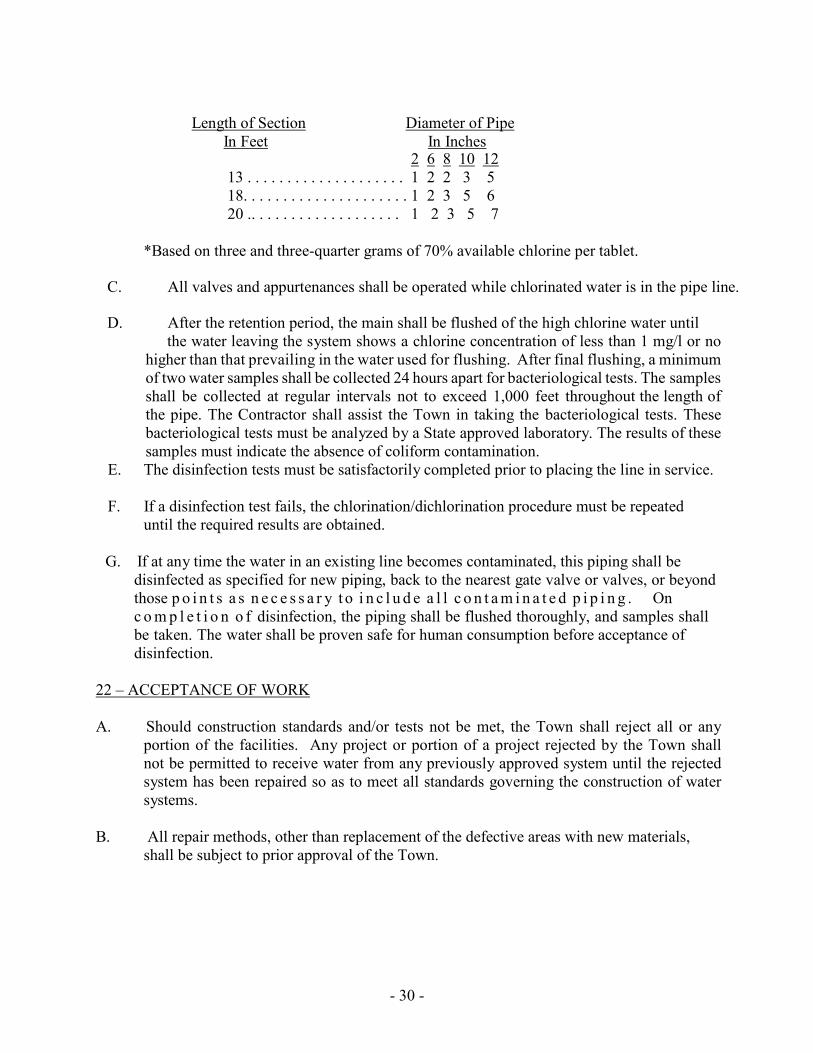
- 30 -
Length of Section Diameter of Pipe
In Feet In Inches 2 6 8 10 12
13 . . . . . . . . . . . . . . . . . . . . 1 2 2 3 5 18. . . . . . . . . . . . . . . . . . . . . 1 2 3 5 6 20 .. . . . . . . . . . . . . . . . . . . 1 2 3 5 7
*Based on three and three-quarter grams of 70% available chlorine per tablet.
C. All valves and appurtenances shall be operated while chlorinated water is in the pipe line.
D. After the retention period, the main shall be flushed of the high chlorine water until the water leaving the system shows a chlorine concentration of less than 1 mg/l or no
higher than that prevailing in the water used for flushing. After final flushing, a minimum of two water samples shall be collected 24 hours apart for bacteriological tests. The samples shall be collected at regular intervals not to exceed 1,000 feet throughout the length of the pipe. The Contractor shall assist the Town in taking the bacteriological tests. These bacteriological tests must be analyzed by a State approved laboratory. The results of these samples must indicate the absence of coliform contamination.
E. The disinfection tests must be satisfactorily completed prior to placing the line in service.
F. If a disinfection test fails, the chlorination/dichlorination procedure must be repeated until the required results are obtained.
G. If at any time the water in an existing line becomes contaminated, this piping shall be
disinfected as specified for new piping, back to the nearest gate valve or valves, or beyond those p o i n t s a s n e c e s s a r y t o i n c l u d e a l l c o n t a m i n a t e d p i p i n g . On c o m p l e t i o n o f disinfection, the piping shall be flushed thoroughly, and samples shall be taken. The water shall be proven safe for human consumption before acceptance of disinfection.
22 – ACCEPTANCE OF WORK
A. Should construction standards and/or tests not be met, the Town shall reject all or any
portion of the facilities. Any project or portion of a project rejected by the Town shall not be permitted to receive water from any previously approved system until the rejected system has been repaired so as to meet all standards governing the construction of water systems.
B. All repair methods, other than replacement of the defective areas with new materials,
shall be subject to prior approval of the Town.

- 31 -
SECTION 3 – SEWER A – DESIGN STANDARDS
1 - GENERAL
A. Design standards shall be those set forth in the Commonwealth of Virginia Sewerage
Regulations, Section 21.00, except as specified herein. B. When the Town deems it necessary, it may specify the type of material to be installed
and/or the construction method to be used. 2 - TRIBUTARY POPULATION
A. Sewer systems shall be designed and sized for complete upstream watershed
development taking the following into consideration:
1. The estimated tributary population for a period of 50 years hence, or
3. The entire watershed shall be assumed to be completely developed according to present or predicted zoning, whichever requires the greater capacity.
B. Minimum allowable population densities shall be as follows:
1. In industrial areas, 40 persons per acre
2. In platted subdivisions, four persons per lot
3. In multi-family developments, four persons per unit
4. All other areas, ten persons per acre.
3 - CAPACITY DESIGN
A. In determining capacities of sanitary sewers, the following factors shall be considered:
1. Average daily flow shall be that set forth in Sec. 23.03.02 C.2 of the Sewerage
Regulations unless actual use figures from similar developments can be shown.
2. Minimum peak design flow for sewers in subdivisions shall be 400 percent of the
average design flow.
4. A minimum peak design flow for mains, trunks, or interceptors shall be 250 percent of the average design flow.

- 32 -
4 - HYDRAULIC DESIGN
A. Sewers shall have a uniform slope and straight alignment between manholes and shall
achieve total containment of wastewater. B. Sewers shall be designed to be free flowing with the hydraulic grade below the crown
and with hydraulic slopes sufficient to provide an average velocity when running full of not less than 2.0 feet per second when using an "n" valve of 0.013 in the Manning Formula.
C. The following are minimum slopes:
Pipe Size in Inches Grade in Percent
4 (service laterals only) 2.00 6 1.00 8 0.50 10 0.32 12 0.24 15 0.20 18 0.16 21 0.12 24 0.10
Pipe sizes shall not be increased just to take advantage of flatter grades. D. In cases where sewers are to be constructed on steep grades for which high velocities are
indicated, the maximum permissible velocity at average flow (before applying peak flow factor) should not exceed 15 feet per second. Suitable drop manholes shall be provided to break the steep slopes and to limit velocities to not more than 15 feet per second.
E. Where drop manholes are impractical for reduction of high velocity, the sewer shall be of
ductile iron. F. Sewer mains connecting to the Town of Woodstock’s trunk line shall have a metering station
just prior to the tie-in.
1. No upstream manhole shall be located closer than 50 feet from the metering station.
2. Uniform alignment should be maintained from upstream manhole through flume to downstream entry point at trunk main or downstream manhole.
3. Pipe slope should not exceed 2.50% and downstream slope should be equal to or
greater than upstream line slope to maintain free flow condition on downstream side of flume.

- 33 -
4. Transitions upstream and downstream of flume should be smooth and uniform and
per flume manufacturer’s requirements.
5. Metering station shall be located outside of the 100-year flood plain. 5 – COLLECTION SYSTEM LAYOUT
A. Manholes shall be provided at all intersections, changes in grade, alignment, pipe
material, or pipe size, and at the termination of a line. Lines installed for future extensions shall also end with a manhole. In addition, manholes shall be provided at intervals not exceeding 400 feet. There shall be a 0.2-foot drop in elevation through the manhole.
B. The use of four-inch service lines is limited to single service connections (laterals).
C. The use of six-inch lines is limited to six or fewer single service connections on cul-de- sacs
and other dead-end lines. D. At all junctions where a smaller diameter sewer discharges into a larger one, the invert of
the smaller pipe shall be at the crown of the larger pipe. E. In undeveloped easements, manholes shall, at a minimum, extend 24 inches above grade.
F. Manholes four feet or less in height (invert out to rim) shall be flat tops.
G. All drop manholes shall have the drop on the inside. Drop shall be a minimum of three feet (see Drawing 14).
H. Lines of six inch or greater diameter shall be connected to the system only at a manhole.
I. Generally, the sewer lateral shall be connected to the sewer pipe. Dead-end manholes
may have laterals into them. Laterals that would discharge within ten feet of an inline manhole may be connected to the manhole. In both cases, the invert of the lateral shall be at the top of the bench.
J. Existing manholes shall be core drilled for the acceptance of new lines.
K. Watertight manhole covers are to be used whenever the manhole tops may be flooded. As
a minimum, watertight covers are to be used to the elevation of the 25-year flood plain. If watertight manhole sewer runs are longer than 1,000 feet, ventilation shall be provided.
L Pipeline deflection of force main lines will only be allowed at joints and fittings. The
length of pipe itself shall not be bent. The maximum deflection limit shall be 12 inches of

- 34 -
lateral displacement per 20 feet of pipe. (If radius is 200 feet or greater, no bends are needed).
M. The tops of sewers crossing streams shall be at a minimum of one foot below the natural
bottom of the stream bed and shall be encased in concrete. N. Standard installation of a new manhole on an existing line shall be cut in (see Drawing
15). For lines 15-inch and greater in diameter, the Town’s engineer may approve a dog house installation (see Drawing 15).
O. Pipe shall be of the same material from manhole to manhole.
P. Wherever possible, sewer laterals shall be ten feet to the right of the water laterals as
viewed from the road toward the lot. Q. The last run of gravity sewer line to a pump station shall be ductile iron pipe. The
minimum run shall be one full laying length. R. The first section of force main leaving a suction lift pump station shall be a full laying
length of ductile iron pipe. 6 – LOCATION
A. Sewers shall be located within legally established streets connections (laterals).
B. The use of six-inch lines is limited to six or fewer single service connections on cul-de-
sacs and other dead-end lines. 7 – DEPTH OF BURY
A. Sewers located in rights-of way or areas subject to wheel loads shall have a minimum of
six feet of cover above the top of the pipe. Sewers in easements not subject to wheel loads shall have a minimum of three feet of cover above the top of the pipe. Where conditions dictate that the cover be less, ductile iron pipe shall be required.
8 – ADJACENT UTILITIES
A. Wherever possible, other utilities shall be placed no closer than five feet horizontally or
eighteen inches vertically (crossings) to a sewer line. The distances are to be measured inside edge to inside edge.
B. Where sewer lines and other utilities cross or where terrain features may dictate, the
Town reserves the right to have the other utilities properly identified with a marker or other means of identification specifically approved by the Town.

- 35 -
9 – SEPARATION OF SANITARY SEWERS AND WATER LINES A. Wherever possible, sewer lines shall be laid at least ten feet horizontally from any water
line. The distance shall be measured edge-to-edge. Should conditions prevent this separation, the water line shall be ductile iron.
B. Sewers crossing under water lines shall be laid to provide a separation of at least 18
inches between the bottom of the water line and the top of the sewer. When conditions prevent this vertical separation, the water line shall be constructed of ductile iron pipe.
C. Water lines passing under sewers shall be ductile iron pipe. In addition, the water line
must be protected by providing:
1. A vertical separation of at least 18 inches between the bottom of the sewer and the top of the water line.
2. Adequate structural support for the sewers to prevent excessive deflection of the
joints.
3. The section of water pipe crossing the sewer line shall be centered at the point of crossing so that its ends are equidistant from the sewer.
D. When it is impossible to obtain proper horizontal and vertical separation, both the water
and sewer shall be constructed of ductile iron pipe. E. No water pipe shall pass through or come into contact with any part of a sewer manhole.
Whenever possible, manholes shall be at least ten feet horizontally from a water main. The distance shall be measured edge-to-edge.
10 – SEPARATION OF SANITARY SEWERS AND STORM SEWERS
A. Sewer lines shall have a minimum separation of 18 inches from storm drainage pipes and
structures. 11 – SEWAGE PUMPING STATIONS
A. Data and design calculations for pump stations and force mains shall be shown on the
plans. Pump station capacity calculations, design elements, pump choice, station schedule and electrical data are to be given. Data and calculations for the total dynamic head (TDH) shall be shown and plainly noted (see Drawing 19).
B. Pump stations shall have three-phase 208-volt power to the site.
C. No underground fuel storage tanks shall be allowed.
D. Pumps shall be wet-well mounted suction lift unless station is low volume.

- 36 -
E. Submersible grinder pumps may be used if:
1. Discharge pipe diameter is 3” or less
2. The TDH is 80 feet or less
3. The peak design flow is 70 gpm or less.
F. A third (spare) pump shall be provided with each submersible grinder pump station.
G. Suction lift stations shall be installed per Drawings 21, 22, and 23.
H. Submersible grinder pump stations shall be installed per Drawings 24, 25, and 26. \ I. All pumping stations shall be equipped with a pump station bypass, as shown on Drawing
30.
J. All sewer lift stations shall be privately owned, operated, and maintained by others. 12 – FORCE MAINS
A. The hydraulic design of force mains shall be based on the following:
1. Force mains shall be designed for a minimum velocity of two (2.0) feet per second
and a maximum velocity of eight (8.0) feet per second.
2. The minimum size of force mains shall be four (4) inches in diameter, except for grinder pumps which shall be two (2) inches.
3. An air release valve shall be placed at all high points in the force main as necessary to
provide for air release that has accumulated in the pipe line.
4. Force main piping and fittings shall be cement-lined ductile iron pipe and shall be designed to meet the maximum pressure of the system.
5. Force mains shall enter the gravity sewer system at a manhole or special junction
chamber. The force main shall enter the termination structure with its centerline horizontal and at a point no higher than one (1) foot above the flow line of the receiving gravity sewer. Design of the force main termination structure shall ensure a smooth flow transition to the gravity flow section to prevent turbulence and release of gases. All interior walls of the force main termination structure shall be coated with coal-tar epoxy.
6. Force mains shall be sufficiently anchored throughout the line length. The number of
bends shall be as few as possible. Thrust blocks, restrained joints, and/or tie rods shall be provided where restraint is needed.

- 37 -
7. All force mains shall be tested at a minimum pressure of at least 50 percent (50%) above the design operating pressure, for at least 30 minutes. Leakage shall not exceed the amount given by the formula contained in the most current AWWA Standards for leakage.
B – MATERIAL SPECIFICATIONS
1 - APPROVED MATERIALS
A. All materials used in the construction of the sewer system shall have the approval of the
Town. AWWA and ASTM set forth only a set of standards for materials. Since these standards are quite broad, they may or may not meet the requirements or needs of the Town.
B. Any materials not listed in these standards and specifications or not currently accepted by
the Town shall be approved by the Town before installation. C. The following approval procedure shall be used:
1. A cover letter along with two sets of manufacturer's certifications, and shop drawings
and/or samples shall be sent to the Town's engineer.
2. After his review, the engineer will issue a letter stating whether the product is
acceptable or not. D. Unapproved materials placed on a job site shall be subject to immediate rejection and
barred from any further consideration. 2 - PIPE
A. Polyvinyl chloride pipe (PVC):
Pipe four inches through fifteen inches in diameter shall meet the requirements of ASTM D-3034. Pipe sizes eighteen inches and greater shall a) meet the requirements of ASTM F-679, b) have a minimum pipe stiffness of 46, and, c) meet T1 wall thickness requirements (for materials with minimum cell classification of 1245 C). Joints shall be bell and spigot with the bell integrally formed with the pipe and comply with ASTM F477. Pipe shall be manufactured by ETI, CertainTeed, Johns-Manville, North American, or our approved equal.
1. Gravity sewer main with 15 feet or less of cover shall be SDR35.
2. Gravity sewer main with cover greater than 15 feet shall be Ductile Iron Pipe.

- 38 -
3. Force main pipe shall be SDR21.
4. Gravity sewer lateral (4") pipe shall be SDR21/SDR35. B. Ductile iron pipe shall conform to the requirements of AWWA Standard C151. The pipe
shall be cement lined in accordance with AWWA Standard C104. Unless otherwise specified, the pipe shall have push-on joints meeting the requirements of AWWA Standard C111. The wall thickness of the pipe shall be Class 52. Pipe shall be manufactured by Griffin Pipe Co., Clow Corporation, or our approved equal and be of a United States/domestic manufacturer.
3 - MANHOLES
A. Manholes shall be pre-cast concrete conforming to ASTM C478 with eccentric cones and
extended bases. Concrete shall conform to the requirements of ASTM C150. Joints shall be O-ring conforming to ASTM C361 (see Drawing 13).
B. Walls shall be a minimum of five inches thick and the base a minimum of eight inches
thick. C. The diameter of the extended base shall be 12 inches greater than the outside of the barrel
section. D. Drop manholes shall use the IntraFlow Low-Profile Inside Drop System by Royal
Environmental Systems, Inc. Outside drops shall not be permitted. E. Manholes for sewer through 24 inches in diameter shall have a four foot inside diameter.
Manholes for sewer greater than 24 inches in diameter shall have a minimum inside diameter of five feet.
F. Pre-cast inverts are acceptable.
G. Pipe shall be secured to the entry hole by a lock joint flexible manhole sleeve as
manufactured by Chardon Rubber Co. or our approved equal. H. The exterior (to include adjustment rings) shall be covered with a black asphalt gilsonite
paint such as LN-12, manufactured by Seaboard Asphalt Products Company, or our approved equal.
I. The joint(s) between the frame and cover, grade ring(s) and cone section shall be sealed by
use of ¾” diameter concrete anchor bolts and one-inch nominal size butyl joint sealant. The sealant shall be CS102 by Concrete Sealants, Inc., or our approved equal.
J. Joints between sections shall be sealed with O-ring gasket and a one-inch nominal size
butyl joint sealant. The butyl sealant shall be CS102 by Concrete Sealants, Inc., or our approved equal. The joint between the top section (cone or flat) and the frame base shall have the same sealant.

- 39 -
4 MANHOLE FRAMES AND COVERS
A. Manhole frames and covers shall conform to ASTM A-48. The frame shall be drilled to
permit using 3/4-inch diameter bolts to secure it to the manhole. Four such bolts shall be used per frame. The words "Sanitary Sewer" shall be cast into the cover so as to be plainly visible.
B. Standard manhole frames and covers shall be: (CONFIRM BELOW)
1. Quality Water Products, style 40, Type A frame with cover labeled sewer
2. B & C model 1012 frame with 1012-A cover
3. East Jordon Iron Works, Inc., catalog number 1545Z1 (frame) and 1970AGS (cover)
with Town of Woodstock Sanitation Sewer lettering
4. Our approved equal and be of a United States/domestic manufacturer.
5. Covers shall be solid with two pick holes. C. Watertight manhole frames and covers shall be:
1. Quality Water Products, Model Pamtight (assembly No. REG1R1FD), with hex-head
stainless steel bolts.
2. East Jordon Iron Works, Inc., Product No. 104509
3. Our approved equal and be of a United States/domestic manufacturer. 5 - FITTINGS
A. PVC fittings in gravity sewer lines shall have the same or greater SDR 35-26 rating as
the pipe used. B. Fittings used in sewer force mains shall be Class 350 ductile iron conforming to ASTM
A536-72, minimum grade 70-50-05. Nominal thicknesses of fittings shall be equal to, or exceed, Class 54 ductile iron pipe thicknesses. Fittings shall be cement lined in accordance with AWWA C504-74. Radii of curvatures shall conform to AWWA C153- 00. They shall be mechanical joint if buried and flanged if used in vault or pump station piping and be of a United States/domestic manufacturer.

- 40 -
6 - VALVES
A. Gate valves:
1. Shall be resilient seat and conform to the specifications set forth in AWWA Standard C504.
2. Shall have a double O-ring stem seal, a minimum stem diameter of 7/8 inch, and will
open left (counter clock-wise)
3. Shall be designed for working pressure not less than that specified for the connecting pipe
4. For buried installation shall have a non-rising stem and mechanical joints conforming
with AWWA Standard C111 unless otherwise specified
5. Used in vault or pump station piping shall have an outside stem and yoke and flanged ends.
6. Gate valves shall be manufactured by MUELLER, American Flow Control 2500
Series, or our approved equal. B. Check valves shall conform with the specifications in AWWA Standard C504. Valves
shall be equipped with an outside weighted arm unless specified otherwise. Valves shall be manufactured by American Darling, or our approved equal.
C. Sewage combination air release and air/vacuum valves shall have cast iron bodies with
stainless steel floats. Other internal parts will be either stainless steel or bronze. Valves will be sized appropriately for each application. Valves shall be Val-MATIC Model VM- 801BWA, or our approved equal.
7 - VALVE BOXES
A. Valve boxes for gate valves shall be two-piece cast iron with a 7 3/8" drop lid marked
"sewer". Boxes shall be screw type adjustable with a 5 1/4" shaft diameter. Adjustment range shall be one foot. The box length shall be determined by depth of bury. The valve box shall be East Jordan Ironworks, Tyler, or our approved equal.
8 - JOINT RESTRAINTS
A. Glands to restrain MJ fittings and pipe bells to DI pipe shall be EBAA Iron megalug
series 1000, Ford uni-flange series 1400, or our approved equal. B. Glands to restrain MJ fittings and pipe bells to PVC pipe shall be EBAA Iron megalug
series 2000PV, Ford uni-flange series 1500, or our approved equal.

- 41 -
C. Glands to restrain PVC pipe bell to spigot shall be EBAA Iron megalug series 6500, Ford uni-flange series 1390, or our approved equal.
D. Glands to restrain DI push joint pipe bell to spigot shall be EBAA Iron Megalug Series
1700, Ford uni-flange series 1450, or our approved equal. 9 - 4” GRAVITY SEWER LATERALS
A. Wyes shall be used to connect the four-inch lateral to the sewer main.
B. If a main has 15 feet or less of cover, material shall be as specified in Drawing 17.
C. If a main has greater than 15 feet of cover, materials shall be as specified in Drawing 18.
10 - 2” FORCE MAIN SEWER LATERALS
A. Saddles for PVC pipe shall be Ford style FS202 or our approved equal.
B. Corporation stops shall have an inlet threaded in accordance with AWWA standard C800
and a male iron pipe outlet. It shall be a Ford Series FB400 or our approved equal. C. The connection at the property line will contain a two-inch ball valve with two-inch
square operating nut. The valve shall be a Ford Series B11 777 or our approved equal. 11 - NEW LINES INTO EXISTING MANHOLES
A. All new openings into existing manholes shall be core drilled. The connection between
the pipe and the manhole shall be made by Kor-N-Seal. 12 - METERING STATIONS
A. Metering s t a t i o ns s h a l l b e r e c t a n g u l a r i n s h a p e a n d c o n t a i n a p a r s h a l l
f l u m e o f appropriate size for present and future flows. The flow shall be monitored by a OCM-3 Open Channel Monitor - PL-384 as manufactured by Miltonic’s equipped with a Model ST-25B or ST-25C transducer for measurement of flows using ultrasonic technology. In non-flood areas, the metering station shall have a Bilco K2 access door or our approved equal. The door shall have a recessed hasp covered by a hinged lid flush with the surface. In flood areas, a watertight manhole frame and cover shall be required.
13 - CLEANOUTS
A. Materials shall be as specified in Drawing 19.

- 42 -
14 – BLOW-OFF ASSEMBLIES A. Materials shall be as specified in Drawing 11.
15 – SEWAGE PUMPING STATIONS
A. Wet wells shall be precast concrete manholes. Concrete shall conform to ASTM C150.
Joints shall be O-ring conforming to ASTM C361. There shall be no steps in the wet well.
1. Suction lift station wet wells shall be eight feet inside diameter. Walls, base, and flat
top shall be a minimum of nine inches thick.
2. Grinder station wet wells shall be six feet inside diameter. Walls shall be a minimum of seven inches thick, and the base a minimum of eight inches thick.
B. The exterior of the wet well shall be covered with a black asphalt gilsonite paint such as
LN-12, manufactured by Seaboard Asphalt Products Company or our approved equal. C. Pipe shall be secured to the entry hole by a lock joint flexible manhole sleeve as
manufactured by Chardon Rubber Co. or our approved equal. D. Each sewage pump shall have an hour meter which shall record accumulated running
time. E. Mercury float switches shall be used.
F. Generator hookup receptacle shall be Russellstoll catalog number SCB 7334-72.
G. Alarm light shall be Edwards model No. 50-R and the horn shall be Edwards model No.
876-N5 or our approved equal. H. There shall be a four-inch mushroom vent in the wet well. It shall be vented to the
atmosphere and contain a bug-proof screen. I. For new sewage pump stations, the automatic dialing alarm system shall be approved by the town prior to installation.
J. Suction lift stations shall have:
1. Pumps manufactured by Smith & Loveless.
2. Self-priming vacuum pumps manufactured by Gast Manufacturing Co., or our approved equal.
3. A 0-10-minute adjustable time delay relay on each vacuum priming pump (to act as a

- 43 -
pump failure sensor). Should a vacuum pump not be able to prime within a pre-set time, the vacuum prime pump will be shut off and an alarm sensor will indicate pump failure.
4. Flanged ductile iron piping in the wet well. Connection between pump station
discharge line and force main piping shall be by solid sleeve with joint restraints. K. Submersible grinder pump stations shall have:
1. Pumps manufactured by Barnes or ABS
2. Stainless steel or pultruded (fiberglass) guide rails
3. Flanged ductile iron piping in the wet well and valve vault
4. Hand wheels on gate valves
5. A floor mounted stainless-steel lifting hoist socket. It shall be for a Halliday Products
hoist model No. D1A24B
6. Electrical controls enclosure containing individual boxes for the items in the enclosure.
L. Two O & M manuals for each station shall be delivered to the Town’s engineer.
M. See Drawings 21 through 27.
16 - REPAIR CLAMPS A. Repair clamps shall be full circle all stainless-steel band as manufactured by Ford, style
FS1, (2" through 12"), and style FS3 (14" through 24"), or our approved equal. Clamps for pipe sizes two-inch through eight-inch diameter shall have a minimum length of 15 inches. Clamps for pipe sizes ten-inch through 12-inch diameter shall have a minimum length of 20 inches. Larger pipe sizes require 24-inch length.
17 - PIPE CASING
A. Casing pipe for sewer mains shall be sized in accordance with Drawing 5. Casing pipe
shall be steel and shall meet ASTM specifications A252 Grade 2, or 139 Grade B. 18 - PIPELINE CASING SPACERS
A. Separation of carrier pipe from casing pipe shall be by manufactured steel and/or plastic
casing spacers. Spacers shall be by PSI, Inc., Recon, or our approved equal. B.

- 44 -
19-LOCATION MARKERS
A. Location markers shall be EMS 1404 Sanitary XR 6-inch non-detectible tape with 12-gauge wire suitable for direct bury 12-18 inches above the pipe.

- 45 -
C – CONSTRUCTION STANDARDS 1 - GENERAL
A. All construction shall be in strict accordance with approved plans and specifications. Any
deviations or changes shall be submitted to the Town for supplemental approval. B. The Town shall have the required number of plans and cut sheets before construction
begins. C. The Town shall have access to the construction work at any time for inspection of work
and construction methods. D. Upon Town acceptance and expiration of warranties, the Town will assume responsibility
for locating water and sewer lines in response to Miss Utility location requests after bond has been returned.
E. The installation of new services on existing lines shall be done at time of utility construction.
Application for, and installation of the service, shall be early in the project to ensure the work is completed in a cost efficient and timely manner.
2 - CLEARING
A. The right-of-way shall be cleared of all trees, stumps, shrubs, and other foreign matter for
a minimum distance of ten feet from each side of the center line of the mains being constructed. The debris shall be disposed of in an acceptable manner. No debris shall be buried within the right-of-way.
3 - EXCAVATION
A. Minimum clearance between the side of the trench and pipe shall be eight inches. The
width of the trench above the top of the pipe may be as wide as necessary for sheeting or bracing and the proper performance of the work. All trench walls should be kept as vertical as possible and still meet OSHA requirements. The trench shall be excavated to a uniform subgrade as required for installation of pipe bedding material.
B. Excavation at manholes and similar structures shall be sufficient to leave at least 12
inches between the structure's outer surface and the embankment or sheeting. C. Excavated material suitable for backfilling shall be piled in an orderly manner and be a
minimum distance of three feet from the bank of the trench. All excavated material not suitable and/or not required for backfill shall be removed and disposed of in an approved manner.
D. Such grading as necessary shall be done to prevent water from flowing into the trench or
other excavations, and any water accumulating therein shall be removed by approved methods.

- 46 -
E. All fill material shall be in place and compacted before sewer lines are installed.
4 - FOUNDATION IN POOR SOIL
A. Wherever the soil at the trench subgrade elevation is soft, unstable, or saturated with
water, such unsuitable material will be removed and the trench subgrade stabilized with a granular stabilization material.
B. Maximum size of granular material shall be two inches.
C. Depth of stabilization shall be as required to construct a firm subgrade for pipe bedding
material but must be at least six inches. D. Concrete arch or cradle bedding shall be provided when necessary (see Drawing 1).
5 - BEDDING
A. Refer to Drawing 1 for types of bedding.
B. Bedding material shall be an open-graded coarse stone aggregate meeting Virginia
Department of Transportation's requirements for size number 68, 78, or 8. C. Standard bedding shall be used unless poor soil conditions are encountered. In this type
bedding, there shall be a minimum of six inches of stone under the pipe. Stone shall also be backfilled around the pipe and to a height of six inches above the top of the pipe. This type of bedding shall also be used with sewer laterals.
D. Holes shall be scooped out where joints occur leaving the entire barrel of the pipe bearing
on the bedding. 6 – PIPE LINE INSTALLATION
A. Force main center line shall be staked at 100-foot intervals and at all bends.
B. After bedding has been installed, pipe and fittings shall be laid in accordance with the
manufacturer's instructions and recommendations. Damaged or unsound material will be rejected.
C. Pipeline deflection of force main lines will only be allowed at joints and at fittings. The
length of pipe itself shall not be bent. The maximum deflection limit shall be 12 inches of lateral displacement per 20 feet of pipe.
D. Force main fittings shall be restrained per the requirements of Drawings 2, 3, and 4.

- 47 -
E. At the completion of the work shift, the end of the installed pipe will be sufficiently plugged to keep out trench waters, soil, and other extraneous material.
F. See Drawing 5 for requirements in making a typical highway crossing.
7 – MANHOLES
A. Manholes are to be constructed of precast concrete in accordance with the Standard
Manhole Detail, Figure 13. Provide monolithic base of precast construction and make water-tight connections between base and risers, unless modifications to the existing system are being performed. Manhole wall and bottom shall be such as to ensure water tightness.
B. Manholes shall be minimum 4 feet inside diameter with a minimum clear opening in the
manhole frame of 24 inches. Manholes shall be maximum 16 feet deep and shall be installed at all changes in sewer size, material, alignment or grade and at terminal end of the sewer. Manholes deeper than 16 feet shall only be considered for approval by the Town in extreme cases with justification provided by the Engineer. Maximum spacing of manholes shall be 350 feet. Crown of inlet sewers shall not be lower than crown of outlet sewer.
C. Drop connection shall be avoided. Drop connection shall provide a minimum drop in a
manhole of two feet measured from the invert of the incoming pipe to the manhole invert (refer to Standard Drawing 14).
D. Construct appropriate flow channels in the bottom of manholes as shown on the Standard
Details and plans. Flow channel construction shall provide a smooth transition between adjacent sewer sections to reduce turbulence. Benches shall be sloped to the channel to prevent accumulation of solids. Provide a positive means of bonding channel to manhole base.
E. The minimum invert drop from inlet to outlet of a manhole shall be 0.20 foot.
F. For repair of existing manholes, joints for brick work and precast concrete block work
shall be completely filled and shall be smooth and free from surplus mortar on the inside of the manhole. Brick shall be laid radially with every sixth course laid as a stretcher course. Brick and concrete block manholes shall be plastered with mortar over the entire outside surface of the walls.
G. All manholes subject to infiltration of ponded surface water and those with top elevations
lower than the 25-year flood elevations shall be provided with watertight manhole frame and bolted cover.
H. Cut all pipes flush with the inside wall of the manhole structure. In all diameter sewer
manholes, provide flexible rubber gasket between manhole wall and the incoming pipe. Provide field sleeve where required to assure a tight fit.

- 48 -
I. Firmly anchor manhole steps to wall according to manufacturer’s recommendations. Steps shall be installed in accordance with Standard Drawing 13.
J. Install manhole frames and covers, as indicated on the plans. Adjust the frame and cover
to finished grade by concrete adjusting ring. Provide flexible plastic gasket between the cover of manholes to be bolted and the manhole frame. Cement the rubber gasket to the frame with a water-resistant material (such as 3M Super Weather Strip Adhesive, Part 8001).
8 – BACKFILLING
A. The Town's specified stone aggregate shall be used to a height of six inches above the top
of the pipe. B. Above the stone aggregate (or concrete arch) shall be 24 inches of select backfill compacted
in six-inch lifts. The maximum particle size of this backfill material shall be one-inch. Backfill shall be compacted to 95% of ASTM 698 maximum density.
C. Above the select backfill, material shall be deposited in lifts not exceeding two feet.
D. Any backfill material used above the pipe bedding shall be free of all organic material,
large clods, frozen soil, or other materials difficult to compact. E. No rock shall be used in the select backfill. Any rock used above the select backfill shall
be no longer than five inches in the greatest dimension. 9 - SERVICE LATERALS
A. The Town shall supervise the installation of sewer service laterals to existing gravity or
force main lines. Location of the tap and the termination point of the lateral is to be coordinated with the Town's engineering assistant.
B. Exact location of sewer services on new lines are to be coordinated with the Town’s
inspector. C. Wherever possible, sewer laterals shall be ten feet to the right of the water laterals as viewed
from the road toward the lot. D. Minimum cover shall be 36 inches.
E. The end of the lateral shall be marked with a treated 2" x 4" stake extending from the cap
to 18 inches above the ground. The top six inches of the 2" x 4" shall be painted green. F. A cleanout assembly shall be furnished at the property line (see Drawing 18).

- 49 -
G. Gravity service laterals are to be laid as shown on Drawings 17 and 18, with minimum grade being 2.00 percent. Only four-inch service laterals shall be tied into gravity sewer lines. (Lines six inches and greater in diameter shall be tied into manholes). Dead-end manholes may have laterals into them. Laterals that would discharge within ten feet of an in-line manhole may be connected to the manhole.
H. A location marker shall be placed five feet before the end of the lateral.
10 – NEW LINE INTO EXISTING MANHOLE
A. Connection to existing manhole shall be made by core drilling. The invert of the new line
shall be at the bench elevation of the existing manhole. 11 – NEW MANHOLE OVER EXISTING SEWER LINE
A. The Town’s engineer shall determine the type of manhole (cut in or dog house) to be
installed. B. A cut in manhole shall be the standard method of installation of a new manhole on an
existing line. C. For lines 15-inch and greater in diameter, the Town’s engineer may authorize use of a
dog house manhole. D. Cut in and dog house manholes shall be installed as specified in Drawing 15.
E. By-pass pumping during installation of the new manhole is required.
12 – BLOW-OFF ASSEMBLIES A. Blow-off assemblies shall be installed as shown on Drawing 11.
13 – AIR RELEASE AND VACUUM VALVES
A. Air release and vacuum valves shall be installed as shown on Drawing 12.
14 – SEWAGE PUMP STATIONS
A. A 12-foot wide paved maintenance road shall be required with a paved turn-around at the
station. B. A eight-foot high fenced-in area with privacy slats (20' x 20' minimum), with a 12-foot
double drive gate shall be required at all grinder pump stations. C. Underground power shall be provided wherever possible with wiring provided for an
emergency generator as shown on Detail 21.

- 50 -
D. No electrical splices or boxes are to be installed in the wet well. E. Two stainless steel clamps shall be used to hold the influent pipe to the wet well sleeve.
F. Flanged ductile iron piping shall be used in the wet well. Connection between pump
station discharge line and force main piping shall be solid sleeve with joint restraints. G. The top of the wet well shall be above the surrounding grade. Suction lift stations shall be
3 to 6 inches above grade and grinder stations shall be 6 to 12 inches above grade.
H. See Drawings 20 through 27.
15 – RESTORATION A. Areas that are disturbed during construction shall be returned to conditions at least equal
to that which existed prior to the start of work. The ground is to be returned to the same contour as existed before construction. Trees, shrubs, etc., in easements are not to be replaced. Disturbed earth surfaces shall be left with ground cover similar to surroundings. Restoration shall commence immediately following the completion of work on any section or division of project.
16 – STREAM CROSSINGS
A. Stream crossings shall be installed as shown on Drawing 6 unless otherwise specified.
The crossing shall be made in such a manner as to minimize erosion and blocking of the stream flow. Backfill under the rip-rap shall be compacted to ninety percent density. Pipe shall be encased in concrete from 10 feet on each side of stream bank.
17 – GRAVITY SEWER LINE INSPECTION AND TESTING
A. On completion of each section of gravity sewer or at such other time as the Town may
direct, the section of sewer is to be cleaned, inspected, and tested. All pipe and service laterals shall be tested by the air-test method.
B. All PVC gravity sewer lines shall be subject to vertical deflection testing. The maximum
allowable deflection following completion of backfill shall not exceed five percent of the pipe's internal diameter. Deflection testing shall be conducted using a properly sized go- no-go mandrel or by other methods as may be adopted by the Town. Any sewer sections failing to meet deflection requirements shall (at the Contractor's expense) be corrected so as to meet all standards governing the construction of sewer mains.
C. All lines and service laterals shall be flow tested to insure no ponding occurs.
D. Sewer line sections shall be visually inspected by means of closed-circuit television. The
inspection will be done one manhole section at a time and recorded on a DVD Disk. In order to verify that the designated sewer section has been adequately examined, the

- 51 -
inspector shall show a street sign, or some type of identifying marker, on the video before entering the manhole.
1. The television camera used for the inspection shall be one specifically designed and
constructed for such inspection. Lighting for the camera shall be suitable to allow a clear picture of the entire periphery of the pipe. The camera shall be operative in 100 percent humidity conditions. The camera shall have a footage recording device and the footage shall be displayed on the monitor. The camera television monitor and other components of the video system shall be capable of producing picture quality to the Town's satisfaction.
2. The camera shall be moved through the entire line in either direction at a moderate
rate. It shall stop when necessary to inspect wyes and to permit proper documentation of the sewer's condition. In no case will the television camera be pulled at a speed greater than thirty feet per minute. Manual winches, power winches, TV cable, and powered rewinds or other devices that do not obstruct the camera's view or interfere with proper documentation of the sewer conditions shall be used to move the camera through the sewer line.
3. When manually operated winches are used to pull the television camera through the
line, telephones or other suitable means of communication shall be set up between the two manholes of the section being inspected to insure good communications between members of the crew.
4. The purpose of the video recording shall be to supply a visual and audio record of the
lines. The recording shall be the property of the Town. The disks shall be given to the Town's engineer. Slow motion or stop-motion playback features may be supplied at the option of the Contractor. The Contractor shall have all disks and necessary playback equipment readily accessible for review by the Town.
E. The Town requires a low-pressure air test be performed on gravity sewer lines.
1. The air test is to be conducted between two consecutive manholes. The test
equipment shall consist of:
a. Two plugs (one tapped and equipped for air inlet connection) b. A shut-off valve c. A pressure regulating valve d. A pressure reduction valve e. A monitoring pressure gauge having a pressure range from 0 to 5 psi, graduated in
0.10 psi increments with an accuracy of + .04 psi. The test equipment shall be set up outside the manhole for easy access and reading.
3. Air shall be supplied to the test slowly and shall be regulated to prevent the pressure
inside the pipe from exceeding 5.0 psi. The pipeline shall be filled until a constant internal pressure of 4.0 psi is maintained. The internal pressure shall be maintained at

- 52 -
4.0 psi or slightly above for a five-minute stabilization period, after which time the internal pressure will be adjusted to 4.0 psi, the air supply shut off and the test begun. For safety reasons, no person shall remain in the manhole while the pipe is being pressurized or throughout the test.
4. For the section of line to pass, there shall be zero leakage for a five-minute interval
after the valve has been shut off.
5. The test must be done in the presence of a Sanitation Town inspector. 18 – FORCE MAIN SEWER LINE INSPECTION AND TESTING
A. The design operating pressure of a force main is expressed as total dynamic head (tdh).
(TDH is measured in feet of water. It is known that 34 feet of water equals 14.7 psi.) The project drawings shall show the TDH.
B. The formula for obtaining the testing pressure (P) shall be:
P = .65 (H) where P = test pressure in psi H = total dynamic head (tdh) in feet of water at design operating point.
C. Specific pressure used in the test shall be subject to the approval of the Town.
D. The air test is to be conducted between the pump station and the line’s discharge manhole.
The test equipment shall consist of:
1. Two plugs (one tapped and equipped for air inlet connection) 2. A shut-off valve 3. A pressure regulating valve 4. A pressure reduction valve 5. A monitoring pressure gauge having a pressure range of 5 psi greater than the
required test pressure. The test equipment shall be set up outside the manhole or pump station for easy access to reading.
E. Air shall be supplied slowly. When the required pressure has been reached, it shall be
maintained for five minutes to insure the pipe's internal pressure has been stabilized. After stabilization, the air supply shall be shut off and the test begun.
F. For the section of line to pass there shall be zero leakage for 60 minutes after the valve
has been shut off. G. The test must be done in the presence of a Town inspector.

- 53 -
19 – MANHOLE AND PUMP STATION WET WELL TESTING A. Manholes and pump stations shall be tested by vacuum only method.
1. Vacuum Method
a. This test method is only applicable to pre-cast concrete manholes.
b. Manholes shall be tested after assembly and prior to backfilling.
c. Stub-outs, manhole boots, and pipe plugs shall be secured to prevent movement while the vacuum is drawn.
d. Installation and operation of vacuum equipment and indicating devices shall be in
accordance with equipment specifications for which performance information has been provided by the manufacturer.
e. A measured vacuum of ten inches of mercury (Hg) shall be established in the
manhole. The time for the vacuum to drop to nine inches of mercury shall be recorded.
f. The maximum allowable leakage rate for a four-foot diameter manhole shall be in
accordance with the following:
Minimum Elapsed Time for a Manhole Depth Pressure Change of 1 Inch Hg 10 ft. or less 60 seconds More than 10 ft., but less than 15 ft. 75 seconds
15 feet or more, but less than 25 ft. 90 seconds
For manholes six feet in diameter, add an additional 30 seconds to the time requirements for four-foot diameter manholes.
g. If the manhole fails the test, necessary repairs shall be made. The vacuum test and

- 54 -
repairs shall be repeated until the manhole passes the test.
B. Manholes shall show no signs of ponding water in the inverts.
20 – ACCEPTANCE OF WORK A. Should construction standards and/or tests not be met, the Town shall reject all or any
portion of the facilities. Any project or portion of a project rejected by the Town shall not be permitted to discharge into any previously approved system until the rejected system or portion of system has been repaired so as to meet all standards governing the construction of sewer mains.
B. All repair methods, other than replacement of the defective areas with new materials,
shall be subject to prior approval of the Town. C. Upon completion of such inspection or tests as required in these specifications, all foreign
matter, (to include but not limited to rock, dirt, concrete, joint sealant, gravel) shall be removed from all sewers and manholes.