developable surfaces with curved...
TRANSCRIPT
Developable Surfaces with Curved Creases
Martin Kilian
TU Vienna
Evolute
Simon Flory
TU Vienna
Evolute
Zhonggui Chen
TU Vienna
Zhejiang University
Niloy J. Mitra
IIT Delhi
Alla Sheffer
UBC
Helmut Pottmann
TU Vienna
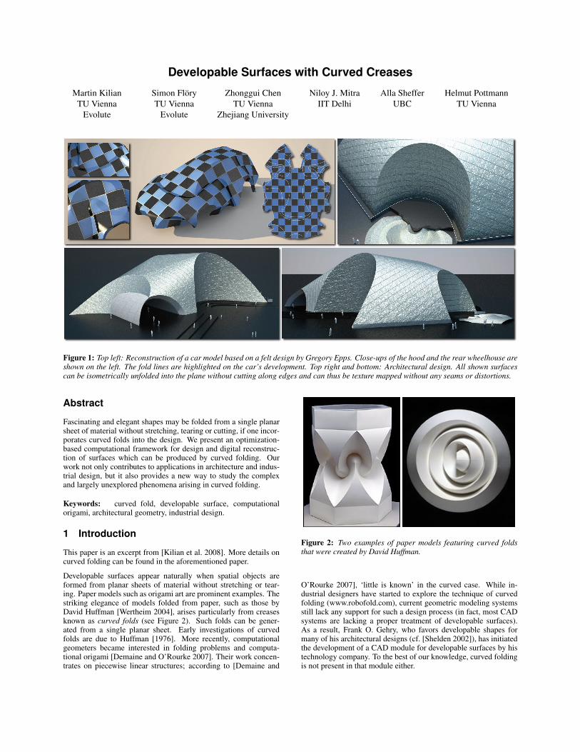
Figure 1: Top left: Reconstruction of a car model based on a felt design by Gregory Epps. Close-ups of the hood and the rear wheelhouse areshown on the left. The fold lines are highlighted on the car’s development. Top right and bottom: Architectural design. All shown surfacescan be isometrically unfolded into the plane without cutting along edges and can thus be texture mapped without any seams or distortions.
Abstract
Fascinating and elegant shapes may be folded from a single planarsheet of material without stretching, tearing or cutting, if one incor-porates curved folds into the design. We present an optimization-based computational framework for design and digital reconstruc-tion of surfaces which can be produced by curved folding. Ourwork not only contributes to applications in architecture and indus-trial design, but it also provides a new way to study the complexand largely unexplored phenomena arising in curved folding.
Keywords: curved fold, developable surface, computationalorigami, architectural geometry, industrial design.
1 Introduction
This paper is an excerpt from [Kilian et al. 2008]. More details oncurved folding can be found in the aforementioned paper.
Developable surfaces appear naturally when spatial objects areformed from planar sheets of material without stretching or tear-ing. Paper models such as origami art are prominent examples. Thestriking elegance of models folded from paper, such as those byDavid Huffman [Wertheim 2004], arises particularly from creasesknown as curved folds (see Figure 2). Such folds can be gener-ated from a single planar sheet. Early investigations of curvedfolds are due to Huffman [1976]. More recently, computationalgeometers became interested in folding problems and computa-tional origami [Demaine and O’Rourke 2007]. Their work concen-trates on piecewise linear structures; according to [Demaine and
Figure 2: Two examples of paper models featuring curved foldsthat were created by David Huffman.
O’Rourke 2007], ‘little is known’ in the curved case. While in-dustrial designers have started to explore the technique of curvedfolding (www.robofold.com), current geometric modeling systemsstill lack any support for such a design process (in fact, most CADsystems are lacking a proper treatment of developable surfaces).As a result, Frank O. Gehry, who favors developable shapes formany of his architectural designs (cf. [Shelden 2002]), has initiatedthe development of a CAD module for developable surfaces by histechnology company. To the best of our knowledge, curved foldingis not present in that module either.

Figure 3: The car model of Figure 1 and its development (topright). The patch decomposition into torsal ruled surfaces is shownusing the following color scheme: planes are shown in yellow,cylinders in green, cones in red, and tangent surfaces in blue. Sam-ple rulings are shown on some patches of the windshield and theside window. Such a segmentation is essential for NURBS surfacefitting and manufacturing.
Motivated by the potential and interest in the use of curved fold-ing for various geometric design purposes, we investigate this topicfrom the perspective of geometric modeling. Developable surfacesare well studied in differential geometry [do Carmo 1976]. Theyare surfaces which can be unfolded into the plane while preservingthe length of all curves on the surface. Developable surfaces arecomposed of planar patches and patches of ruled surfaces with thespecial property that all points of a ruling have the same tangentplane. Such torsal ruled surfaces consist of pieces of cylinders,cones, and tangent surfaces, i.e., their rulings are either parallel,pass through a common point, or are tangent to a curve (curve ofregression), respectively. Whereas a torsal ruled surface has onlyone continuous family of rulings, general smooth developable sur-faces are usually a much more complicated combination of patches.The presence of planar parts is the main source of this huge varietyof possibilities. The level of difficulty is further increased if oneadmits creases, i.e., curved folds (see Figure 3).
2 Discrete developable surfaces
Developable surfaces. As our basic representation of devel-opable surfaces we employ quad-dominant meshes with planarfaces, which is also the representation of choice for discrete dif-ferential geometry [Sauer 1970; Bobenko and Suris 2005].
A strip of planar quadrilaterals (Figure 4, left) is a discrete modelof a torsal ruled surface. Such a ‘PQ strip’ can be trivially un-folded into the plane without distortions. The edges where succes-sive quads join together give us the discrete rulings. In general theyform the edge lines of the regression polyline r0, r1, . . . ; in specialcases the discrete rulings are parallel, or pass through a fixed point.A refinement process which maintains planarity of quads generates,in the limit, a torsal ruled surface Σ (Figure 4, right). Its rulings arethe limits of the discrete rulings, which in general are tangent to theregression curve r(t), and in special cases are parallel (cylinder), orpass through a fixed point (cone).
The representation of developable surfaces as PQ strips providesvarious advantages over triangle meshes: (i) developability is guar-anteed by planarity of faces and the development is easily obtained,(ii) subdivision applied to PQ strips provides a simple and compu-tationally efficient multi-scale approach [Liu et al. 2006], (iii) theregression curve – which is singular on the surface and thus needsto be controlled – is present in a discrete form, and (iv) the cur-vature behavior can be easily estimated as shown in [Kilian et al.2008].
Curved folds. In the smooth setting, the following fact aboutcurved folds is well known (see e.g. [Huffman 1976]): At eachpoint of a fold curve c, the osculating plane of c is a bisectingplane of the tangent planes on either side of the fold. This fol-lows immediately from the identical geodesic curvatures of the foldcurve c with respect to the two adjacent developable surfaces S1
and S2. Hence, given the surface on one side of a fold curve, wecan compute (part of) the other as the envelope of planes, obtainedby reflecting the tangent planes about the osculating planes of c.This is discussed in some detail in [Pottmann and Wallner 2001],but one finds only that part of S2 whose rulings meet c. Thus, theapproach is not sufficient for most of our tasks where, in addition,multiple folds may appear, and the locations of such fold curvesonly become known in the process of optimization. In contrast tothe smooth setting, in the discrete case there are more degrees offreedom in choosing the surface S2. This fact necessitates an opti-mization approach as described next.
3 The basic optimization algorithm
The basic optimization algorithm simultaneously optimizes a dis-crete developable surface M and its planar development P . Tomaintain isometry between corresponding faces of M and P , weoriginally let M be a quad-dominant soup of planar polygons M i inspace. These polygons are isometric to the corresponding faces P i
in the planar mesh P , see Figures 5 and 6. During the optimization,the polygon soup M will become a mesh via a registration proce-dure which bears some similarity to that used in the PRIMO meshdeformation tool [Botsch et al. 2006]. However, our optimizationrequires more sophistication since we have to simultaneously opti-mize the development P while satisfying various other constraints.
r0
p0
q0
r1
r2
r3
r4
c0c1c1c1c1c1c1c1c1c1c1c1c1c1c1c1c1c1
C
P1
r(t)
n1n1n1n1n1n1n1n1n1n1n1n1n1n1n1n1n1 n(t)n(t)n(t)n(t)n(t)n(t)n(t)n(t)n(t)n(t)n(t)n(t)n(t)n(t)n(t)n(t)n(t)
ΣΣΣΣΣΣΣΣΣΣΣΣΣΣΣΣΣ
Figure 4: A PQ strip (left) is a discrete model of a developable sur-face Σ (right). The intersections of edges piqi of adjacent planarquads generate the regression polyline ri. In the limit of a refine-ment process, this regression polyline becomes the regression curver(t). Polylines C, whose edges cici+1 intersect inner bisectors ofconsecutive discrete rulings at right angles, are discrete versionsof principal curvature lines, and serve for the definition of discretecurvatures. The unit normals to planar quads Pi are denoted by ni.

Optimization starts with an initial set of pairs (M i, P i) of isometric
planar polygons (primarily quads in our setting). The faces P i forma planar mesh P , while in space the corresponding polygons M i
are assumed to roughly represent a developable shape D. They arenot yet precisely aligned along edges. Thus M is not a mesh buta polygon soup. See [Kilian et al. 2008] on how to compute initialpositions P i for different applications.
The unknowns. We introduce a Cartesian coordinate system inthe plane of P , with origin o and basis vectors e1, e2. Each face P i
of P is congruent to the respective face M i in space. For each suchface, the image of (o; e1, e2) under the isometric transformation
P i7→ M i is a Cartesian frame (oi, ei
1, ei2) in the plane of the
face M i. If (px, py) are the coordinates of a vertex p of P i, then
the corresponding vertex m of M i is m = oi + pxe
i1 + pye
i2.
During the optimization, the frames (oi, ei1, e
i2) undergo a spatial
motion, and the coordinates (px, py) can also vary since we allow
the polygons P i to change.
We linearize the spatial motion of any face M i using an instanta-neous velocity vector field: The velocity of a point x can be repre-sented as v(x) := c
i + ci×x, where c
i, ci are vectors in 3-space.Thus a vertex m+ of the displaced quad face is given by:
m+ = m + ci + c
i× o
i + px(ci× e
i1) + py(ci
× ei2).
The new vertex position is linear in the unknown parametersc
i, ci∈ R
3 of the velocity field, and also linear in the unknowncoordinates px, py . We optimize over both the velocity parametersand the coordinates. The products pxc
i and pyci result in non-
linear terms if we insist on simultaneously optimizing them. Toavoid nonlinear optimization, we alternately optimize for displace-ments c
i, ci and for vertex coordinates px, py . Since our objectivefunction is quadratic in both types of unknowns this amounts toalternately solving two sparse systems of linear equations.
Applying displacements corresponding to c, c destroys the exactisometric relation between corresponding faces Pi and Mi. It istherefore necessary to further modify the vertices of M i. This caneither be done by rigid registration of the face P i to the estimated
vertex locations mj+ as proposed by Botsch et al. [2006], or by
using a helical motion as described in [Pottmann et al. 2006] – weuse the former approach.
The objective function. Our objective function is designed tosimultaneously ensure that M becomes a mesh, fits the input data,and satisfies the aesthetic requirements of the application.
If a vertex p in the planar mesh P is shared by k faces, then p cor-responds to k different vertices m
1, . . . ,mk of the correspondingk faces in M . Since these vertices should agree in the final mesh,we use a vertex agreement term of the form:
Fvert :=X
(mi+ − m
j+)2,
where the sum extends over all`
k
2
´
combinations per vertex p ∈ P ,and over all vertices in P .
Pi
Pi
Pi
Pi
Pi
Pi
Pi
Pi
Pi
Pi
Pi
Pi
Pi
Pi
Pi
Pi
Piooooooooooooooooo
oi
oi
oi
oi
oi
oi
oi
oi
oi
oi
oi
oi
oi
oi
oi
oi
oie1e1e1e1e1e1e1e1e1e1e1e1e1e1e1e1e1
ei
1e
i
1e
i
1e
i
1ei
1ei
1e
i
1e
i
1e
i
1e
i
1e
i
1e
i
1e
i
1e
i
1e
i
1e
i
1ei
1
e2e2e2e2e2e2e2e2e2e2e2e2e2e2e2e2e2e
i
2e
i
2e
i
2e
i
2ei
2ei
2e
i
2e
i
2e
i
2e
i
2e
i
2e
i
2e
i
2e
i
2e
i
2e
i
2ei
2
D
Mi
m1
m2
p
Figure 5: Basic setup for the optimization when a reference surfaceD is used. Faces with the same color are congruent.
MiMiMiMiMiMiMiMiMiMiMiMiMiMiMiMiMi PiPiPiPiPiPiPiPiPiPiPiPiPiPiPiPiPi
Figure 6: Top left: Initial polygon soup M . Top right: Develop-ment P . Bottom left: M after subdivision and optimization. Bottomright: M after three rounds of subdivision and optimization.
For M to approximate an underlying data surface D, we include afitting term Ffit which is quadratic in the vertex coordinates m. Letmc denote the closest point in D to m, and let nc denote the unitnormal at mc to the underlying surface. We use a linear combina-tion of the squared distance (m−mc)
2 and the squared distance tothe tangent plane [(m − mc) · nc]
2 as the data fitting term. Whenfitting curves, especially near boundaries, we use tangent lines in-stead of tangent planes.
Finally, we need a fairness term Ffair. For each pair of adjacentquads M i and M j of the PQ strip, we use the discrete bending en-
ergy wij(ni+ − n
j+)2 of the corresponding developable surface as
described in [Kilian et al. 2008] as the fairness term. The normal ofa quad M i of M is given by n
i = ei1 × e
i2. Under small displace-
ments, this normal linearly varies as ni+ = n
i + ci× n
i. Givena polyline (p1, . . .pn) representing a fold line, i.e., a crease or asegment of a boundary curve, the contribution to Ffair is a sum ofsquared second differences
P
(pi−1−2pi+pi+1)2. Fairness terms
are also applied to the respective polylines in the planar domain P .
The fairness term Ffair alone is not always sufficient to maintainconvex quads, and to prevent flips in the planar mesh P , espe-cially when the quads become thin after several steps of subdivi-sion. Hence we add another term Fconv to enforce convexity. Weassume that the orientation of each face of P coincides with theorientation of the plane induced by the frame (o; e1, e2). A corner(pi−1,pi,pi+1) of a planar polygon is convex if and only if theoriented area of the triangle ∆(pi−1,pi,pi+1) is positive. Thisterm also prevents flipping of faces.
The algorithm. Combining all individual terms, our basic opti-mization problem reads
minimize F = Fvert + λFfit + µFfair
subject to Fconv ≥ 0.(1)
We alternately minimize the objective function over new positionsof vertices in P , and displacements of faces in space, i.e., velocityvectors for the corresponding face planes. Note that the weights wij
(see [Kilian et al. 2008]) of Ffair, which only depend on the planarmesh P , remain fixed when optimizing for displacements of faces

Figure 7: A gallery of digi-tal paper models. Models werecomputed with scans of real pa-per models as reference sur-faces. Reconstructed models ex-hibit curved and straight foldsand can be isometrically un-folded into the plane. Severalspecial cases like cone singular-ities (top row – middle) and con-verging curved folds (top row –right) are shown.
in space and the side condition Fconv is also not needed. Hence,the spatial sub-problem amounts to solving a sparse linear system,and subsequent application of the corresponding rigid body motionper face. Optimizing the development P is more involved sincethe weights wij change in a non linear way as the geometry of Pchanges. Additionally we have a quadratic term Fconv to maintainconvexity as a side constraint. With the meshes scaled to fit insidea unit cube, we found λ = 1 and µ = 10−4 to be good values tostart the optimization.
Given an initial mesh P and a polygon soup M that roughly ap-proximates a developable shape, we alternately optimize for P andM . The optimization terminates when the vertex agreement termfalls below a given threshold. For the next refinement level, we sub-divide the current mesh P , and map the new faces to space usingthe rigid transformation associated with the faces of P at the cur-rent level. The refinement process splits each quad of P to formtwo new ones. Splitting is performed along the edges that do notcorrespond to ruling directions (see Figure 4, right). The process isrepeated until desired accuracy is reached.
Acknowledgements
This work is supported by the Austrian Science Fund (FWF) undergrants S92 and P18865 and a Microsoft outstanding young facultyfellowship. We are grateful to H. Schmiedhofer for his help withbuilding and scanning the paper models and rendering the recon-structed models. We thank M. Peternell and J. Wallner for theirthoughtful comments on the subject.
References
BOBENKO, A., AND SURIS, Y., 2005. Discrete differential geom-etry. Consistency as integrability. Preprint, http://arxiv.org/abs/math.DG/0504358.
BOTSCH, M., PAULY, M., GROSS, M., AND KOBBELT, L. 2006.Primo: coupled prisms for intuitive surface modeling. In Symp.Geom. Processing, 11–20.
DEMAINE, E., AND O’ROURKE, J. 2007. Geometric FoldingAlgorithms. Cambridge Univ. Press.
DO CARMO, M. 1976. Differential Geometry of Curves and Sur-faces. Prentice-Hall.
HUFFMAN, D. A. 1976. Curvature and creases: a primer on paper.IEEE Trans. Computers C-25, 1010–1019.
KILIAN, M., FLORY, S., CHEN, Z., MITRA, N. J., SHEFFER, A.,AND POTTMANN, H. 2008. Curved folding. ACM Transactionson Graphics 27, 3. to appear.
LIU, Y., POTTMANN, H., WALLNER, J., YANG, Y.-L., AND
WANG, W. 2006. Geometric modeling with conical meshesand developable surfaces. ACM Trans. Graphics 25, 3, 681–689.
POTTMANN, H., AND WALLNER, J. 2001. Computational LineGeometry. Springer.
POTTMANN, H., HUANG, Q.-X., YANG, Y.-L., AND HU, S.-M.2006. Geometry and convergence analysis of algorithms for reg-istration of 3D shapes. Int. J. Computer Vision 67, 3, 277–296.
SAUER, R. 1970. Differenzengeometrie. Springer.
SHELDEN, D. 2002. Digital surface representation and the con-structibility of Gehry’s architecture. PhD thesis, M.I.T.
WERTHEIM, M. 2004. Cones, Curves, Shells, Towers: He MadePaper Jump to Life. The New York Times, June 22.