develop a multiple interface based fire fighting robot · develop a multiple interface based fire...
TRANSCRIPT

Develop a Multiple Interface Based Fire Fighting Robot 47
Develop a Multiple Interface Based Fire Fighting Robot
Ting L. Chien , Kuo Lan Su and Sheng Ven Shiau
x
Develop a Multiple Interface Based Fire Fighting Robot
Ting L. Chien1 , Kuo Lan Su2 and Sheng Ven Shiau3
1Department of Electronic Engineering WuFeng Institute of Technology Ming-Hsiung, Chia 621, Taiwan [email protected]
2 Department of Electrical Engineering National Yunlin University of Science & Technology Douliou, Yunlin 640, Taiwan,[email protected]
3Graduate school Engineering Science and technology National Yunlin University of Science & Technology Douliou, Yunlin 640, Taiwan [email protected]
1. Abstract
The security of home, laboratory, office, factory and building is important to human life. We develop an intelligent multisensor based security system that contains a fire fighting robot in our daily life. The security system can detect abnormal and dangerous situation and notify us. First, we design a fire fighting robot with extinguisher for the intelligent building. The fire fighting robot is constructed using aluminum frame. The mobile robot has the shape of cylinder and its diameter, height and weight is 50 cm, 130 cm and 80kg. There are six systems in the fire fighting robot, including structure, avoidance obstacle and driver system, software development system, fire detection, remote supervise system and others. We design the fire detection system using two flame sensors in the fire fighting robot, and program the fire detection and fighting procedure using sensor based method. We design a low cost based obstacle detection module using IR sensors and ultrasonic sensors in the mobile robot. The man-machine interface of the fire fighting robot must be mobility and convenience. We use touch screen to display system status, and design a general user interface (GUI) on the touch screen for the mobile robot. Finally, we implement the fire detection system using fire fighting robot. If fire accident is true, the fire fighting robot can uses two flame sensors to find out fire source by the proposed method, and move to fire source to fight the fire using extinguisher. Keywords:fire fighting robot、man-machine interface、touch screen
2. Introduction
Home can provide safety, convenience, and efficiency for people in the 21st century. An intelligent home system is integrated by many function and systems. One of the most important systems is the fire detection function system in an intelligent home [1,- 6]. The fire event may involve dangerous in life. In generally, the fire detection device is fixed on the
4

Mechatronic Systems, Applications48
wall or ceiling. But the method is not flexibility to detect fire event. It is not very convenience that uses many fire detection modules in the home. In the paper, we design a fire fighting robot to detect fire event, and use extinguish to fight the fire source, and can transmits the fire event to the remote supervised computer using RF interface and Internet, and transmit fire information to cell phone using GSM modern. In the past literatures, many experts research in the service robot. Some research addressed in developing target-tracking system of service robot [11,12], such as Hisato Kobayashi et al. proposed a method to detect human being by an autonomous mobile guard robot [13]. Yoichi Shimosasa et al. developed Autonomous Guard Robot [10] witch integrate the security and service system to an Autonomous Guard Robot, the robot can guide visitors in daytime and patrol in the night. D. A. Ciccimaro developed the autonomous security robot – “ROBART III” which equipped with the non-lethal-response weapon [8,9]. Moreover, some research addressed in the robot has the capability of fire fighting [7]. There are some products that have been published for security robot. Such as SECON and SOC in Japanese, and International Robotics in USA, and Chung Cheng #1 in Taiwan [20]. Wang et al [14] develops a multisensor fire detection algorithm using neural network. One temperature and one smoke density sensor signal are fused for ship fire alarm system. Healey et al. [15] presents a real-time fire detection system using color video input. The spectral, spatial, and temporal properties of fire were used to derive the fire-detection algorithm. Neubauer [16] apply genetic algorithms to an automatic fire detection system. The on-line identification of stochastic signal models for measured fire signals was presented. Ruser and Magori [17] described the fire detection with a combination of ultrasonic and microwave Doppler sensor. Luo and Su [18,19] use two smoke sensors, two temperature sensors and two flame sensors to detect fire event, and diagnosis which sensor is failure using adaptive fusion method. The chapter is organized as follows: Section II describes the system structure of the automatic fire fighting system. Section III presents the function of the fire fighting robot. Section IV explains the avoidance obstacle algorithm for the fire fighting robot, and the simulation and experimental result and scenario is implemented in section V. Section VI presents brief concluding comments.
3. System Architecture
The system architecture of the home security system is shown in Fig 1. The system contains fire fighting robot, television, remote supervise computer, GSM modern, security modules, appliance control modules and wireless RF controller. The robot and security device can receive the status of security module and appliance control module using wireless RF interface. In the security modules, they use one-way communication with the fire fighting robot. But the appliance control modules use two-way communication with the fire fighting robot. The fire fighting robot can communicate with GSM modern via RS232 interface, and can communicate with the remote supervise computer via wireless Internet. The display panel of the remote supervised computer is television, and users can control the fire fighting robot using wireless RF controller. The fire fighting robot can get detection signals from security modules via wireless RF interface. The remote supervise computer can interact with the mobile robot via wireless Internet. Users can use the remote supervised computer to get security information of the
home or building, and control the fire fighting robot to everywhere in the home. The mobile robot can transmit the reality status to the remote supervise computer via wireless Internet, and transmits the message to mobile phone using GSM modern. Fig. 1. The overview of the home security
The main controller of the fire fighting robot is industry personal computer (IPC). The hardware devices have display device (touch panel), extinguisher, CCD, two flame sensors and sensory circuits, driver system (DC servomotors, NI motion control card and MAXON drivers), GSM modem and wireless RF interface. The remote supervised computer is personal computer (PC) with a Pentium-IV 2.4G CPU. There are six systems in the fire fighting robot, including structure, avoidance obstacle and driver system, software development system, fire detection, remote supervise system and others. Fig. 2 is the structure of the fire fighting robot, and each system includes some subsystem. Each system contains some functions in the fire fighting robot. Fig. 2. The structure of the fire fighting robot.
4. Fire Fighting Robot
The block diagram of the fire fighting robot is shown in Fig. 3. In the drive system, there are fire fighting device, auto-charging device, and the robot can control appliance module via wireless RF interface. In the motion control function, the mobile robot can orders command to control two DC servomotors through motion control card and driver devices, and it can control two robot arms using the motion control card. In the avoidance obstacle function, the robot catches eight IR sensor signals by digital input terminal (in the motion control

Develop a Multiple Interface Based Fire Fighting Robot 49
wall or ceiling. But the method is not flexibility to detect fire event. It is not very convenience that uses many fire detection modules in the home. In the paper, we design a fire fighting robot to detect fire event, and use extinguish to fight the fire source, and can transmits the fire event to the remote supervised computer using RF interface and Internet, and transmit fire information to cell phone using GSM modern. In the past literatures, many experts research in the service robot. Some research addressed in developing target-tracking system of service robot [11,12], such as Hisato Kobayashi et al. proposed a method to detect human being by an autonomous mobile guard robot [13]. Yoichi Shimosasa et al. developed Autonomous Guard Robot [10] witch integrate the security and service system to an Autonomous Guard Robot, the robot can guide visitors in daytime and patrol in the night. D. A. Ciccimaro developed the autonomous security robot – “ROBART III” which equipped with the non-lethal-response weapon [8,9]. Moreover, some research addressed in the robot has the capability of fire fighting [7]. There are some products that have been published for security robot. Such as SECON and SOC in Japanese, and International Robotics in USA, and Chung Cheng #1 in Taiwan [20]. Wang et al [14] develops a multisensor fire detection algorithm using neural network. One temperature and one smoke density sensor signal are fused for ship fire alarm system. Healey et al. [15] presents a real-time fire detection system using color video input. The spectral, spatial, and temporal properties of fire were used to derive the fire-detection algorithm. Neubauer [16] apply genetic algorithms to an automatic fire detection system. The on-line identification of stochastic signal models for measured fire signals was presented. Ruser and Magori [17] described the fire detection with a combination of ultrasonic and microwave Doppler sensor. Luo and Su [18,19] use two smoke sensors, two temperature sensors and two flame sensors to detect fire event, and diagnosis which sensor is failure using adaptive fusion method. The chapter is organized as follows: Section II describes the system structure of the automatic fire fighting system. Section III presents the function of the fire fighting robot. Section IV explains the avoidance obstacle algorithm for the fire fighting robot, and the simulation and experimental result and scenario is implemented in section V. Section VI presents brief concluding comments.
3. System Architecture
The system architecture of the home security system is shown in Fig 1. The system contains fire fighting robot, television, remote supervise computer, GSM modern, security modules, appliance control modules and wireless RF controller. The robot and security device can receive the status of security module and appliance control module using wireless RF interface. In the security modules, they use one-way communication with the fire fighting robot. But the appliance control modules use two-way communication with the fire fighting robot. The fire fighting robot can communicate with GSM modern via RS232 interface, and can communicate with the remote supervise computer via wireless Internet. The display panel of the remote supervised computer is television, and users can control the fire fighting robot using wireless RF controller. The fire fighting robot can get detection signals from security modules via wireless RF interface. The remote supervise computer can interact with the mobile robot via wireless Internet. Users can use the remote supervised computer to get security information of the
home or building, and control the fire fighting robot to everywhere in the home. The mobile robot can transmit the reality status to the remote supervise computer via wireless Internet, and transmits the message to mobile phone using GSM modern. Fig. 1. The overview of the home security
The main controller of the fire fighting robot is industry personal computer (IPC). The hardware devices have display device (touch panel), extinguisher, CCD, two flame sensors and sensory circuits, driver system (DC servomotors, NI motion control card and MAXON drivers), GSM modem and wireless RF interface. The remote supervised computer is personal computer (PC) with a Pentium-IV 2.4G CPU. There are six systems in the fire fighting robot, including structure, avoidance obstacle and driver system, software development system, fire detection, remote supervise system and others. Fig. 2 is the structure of the fire fighting robot, and each system includes some subsystem. Each system contains some functions in the fire fighting robot. Fig. 2. The structure of the fire fighting robot.
4. Fire Fighting Robot
The block diagram of the fire fighting robot is shown in Fig. 3. In the drive system, there are fire fighting device, auto-charging device, and the robot can control appliance module via wireless RF interface. In the motion control function, the mobile robot can orders command to control two DC servomotors through motion control card and driver devices, and it can control two robot arms using the motion control card. In the avoidance obstacle function, the robot catches eight IR sensor signals by digital input terminal (in the motion control

Mechatronic Systems, Applications50
card), and measure distance of obstacle using eight ultrasonic sensors via series interface. We use microprocessor to drive eight ultrasonic sensors, and transmit distance range to main controller of the fire fighting robot via series interface. We design ultrasonic driver circuit and use multisensor fusion method to get exactly decision output. In the sensory system, there are fire detection, power detection and environment detection. The transmission interface between the remote supervise computer and the fire fighting robot is wireless Internet. There are some devices communicate with the main controller of the fire fighting robot. Such as touch screen, wireless image, wireless RF interface, alarm device and GSM modem. Fig. 3. The block diagram of the fire fighting robot.
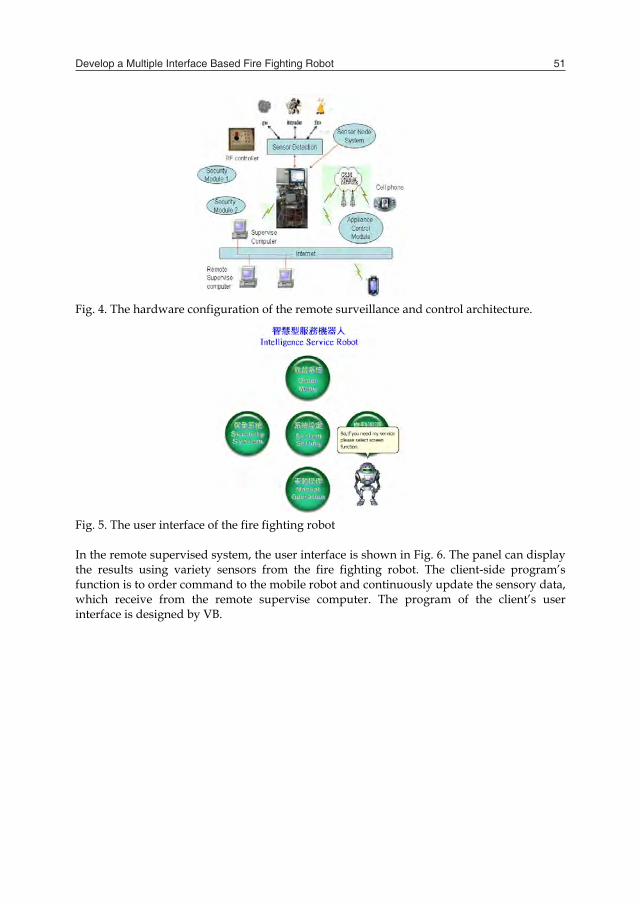
In the hierarchy of the remote supervise system, it contains communication protocol, data base and user interface. The hardware configuration of the remote supervise system includes a fire fighting robot, supervised computer, GSM modem and wireless LAN, as show in Fig. 4. The main controller of the fire fighting robot can get sensor signals to detect fire, intruder, gas, etc, and can interact with the remote supervise computer via wireless Internet. Users can control the fire fighting robot via wireless Internet, too. The remote user cans logo in the supervise computer to control the fire fighting robot, and can connect to the Web server or the robot server to get all information by computer or cell phone through the Internet. The user interface of the fire fighting robot is shown in Fig. 5. The display panel contains five parts. In the security system, it can display detection results using variety sensors, and display the state of motor and battery, and display the detection results using sensors from the fire fighting robot. The program language of the user interface is designed by VB. The fire fighting robot communicates with mobile phone using GSM (Global System for Mobile) modular. The GSM modular (WMOD2) was made by Wavecom.. The modular is a seft-contained E-GSM900/GSM1800 (or E-GSM900/ GSM1900) dual band module.
Fig. 4. The hardware configuration of the remote surveillance and control architecture.
Fig. 5. The user interface of the fire fighting robot In the remote supervised system, the user interface is shown in Fig. 6. The panel can display the results using variety sensors from the fire fighting robot. The client-side program’s function is to order command to the mobile robot and continuously update the sensory data, which receive from the remote supervise computer. The program of the client’s user interface is designed by VB.
Develop a Multiple Interface Based Fire Fighting Robot 51
card), and measure distance of obstacle using eight ultrasonic sensors via series interface. We use microprocessor to drive eight ultrasonic sensors, and transmit distance range to main controller of the fire fighting robot via series interface. We design ultrasonic driver circuit and use multisensor fusion method to get exactly decision output. In the sensory system, there are fire detection, power detection and environment detection. The transmission interface between the remote supervise computer and the fire fighting robot is wireless Internet. There are some devices communicate with the main controller of the fire fighting robot. Such as touch screen, wireless image, wireless RF interface, alarm device and GSM modem. Fig. 3. The block diagram of the fire fighting robot.
In the hierarchy of the remote supervise system, it contains communication protocol, data base and user interface. The hardware configuration of the remote supervise system includes a fire fighting robot, supervised computer, GSM modem and wireless LAN, as show in Fig. 4. The main controller of the fire fighting robot can get sensor signals to detect fire, intruder, gas, etc, and can interact with the remote supervise computer via wireless Internet. Users can control the fire fighting robot via wireless Internet, too. The remote user cans logo in the supervise computer to control the fire fighting robot, and can connect to the Web server or the robot server to get all information by computer or cell phone through the Internet. The user interface of the fire fighting robot is shown in Fig. 5. The display panel contains five parts. In the security system, it can display detection results using variety sensors, and display the state of motor and battery, and display the detection results using sensors from the fire fighting robot. The program language of the user interface is designed by VB. The fire fighting robot communicates with mobile phone using GSM (Global System for Mobile) modular. The GSM modular (WMOD2) was made by Wavecom.. The modular is a seft-contained E-GSM900/GSM1800 (or E-GSM900/ GSM1900) dual band module.
Fig. 4. The hardware configuration of the remote surveillance and control architecture.
Fig. 5. The user interface of the fire fighting robot In the remote supervised system, the user interface is shown in Fig. 6. The panel can display the results using variety sensors from the fire fighting robot. The client-side program’s function is to order command to the mobile robot and continuously update the sensory data, which receive from the remote supervise computer. The program of the client’s user interface is designed by VB.

Mechatronic Systems, Applications52
Fig ThthedehadeFiganint
Fig
5.
In anusiSM650ult8.
g. 6. The remote s
he security moduese modules is mtection module, gppen, these securvice. The securityg 7(b). The appliad feedback the aterface.
g. 7.The security m
Avoidance Ob
the avoidance obd infrared sensoing multisensor f
MC-60R infrared 00 ultrasonic rangtrasonic sensors t
supervise interfac
ule and appliancemicroprocessor (Agas detection mority modules cany module is showance control mod
action result to th
(a) module and appl
bstacle System
bstacle and driveors to detect obsfusion and integrreflection (IR) sege sensors to meato decide the map
ce of the fire fight
e control moduleATMEL89C2051). odule, intruder den transmit RF signwn in Fig 7(a). Thdules can controlhe mobile robot a
liance control mo
m
er system, the firtacle and restruc
ration technique. ensors to detect oasure the distancp of environment
ting robot
e are designed b In the security metection module, nal to the mobile
he appliance contrl appliance devicand the security
(b) dule
e fighting robot cture the surrounThe fire fighting
obstacle, and usee from obstacle. W
t. The detection m
y us. The contromodule, it contai etc. When the st
e robot and the serol module is shoce using relay eledevice via wirel
uses ultrasonic snding environme robot uses eight
es eight pieces PoWe fuse IR senso
module is shown
oller of ins fire tatus is ecurity own in ement, ess RF
sensors ent by pieces olaroid ors and in Fig.
Fig. 8. The IR and ultrasonic detection module
There are two type objects are defined as “obstacle” and “free space”, as shown in Fig. 9. Eight infrared sensors are used for obstacle detection in the uncertain environment, where each sensor is set on fixed location around the fire fighting robot. The angle is
4 from X
axis to the centre of infrared beam. The radius of the robot is R (R=25cm), and the distance between the robot and obstacle is Di at sensor modular i, and the safe distance (infrared reflection senor detection distance) between robot and obstacle is Ds. The Ds is a threshold to ensure that the fire fighting robot is not closes the obstacle. First, we define the relation function of infrared sensor is fD
01
fD (1)
Then we define the relation function of ultrasonic sensor is uD
safess
safe
safeS
u DDD
DDD
D1
(2)
We can calculate the decision value of reliability of the obstacle detection at sensor module i to be defined iD , and the decision value of reliability of the obstacle detection between the ultrasonic sensor module i and the ultrasonic sensor module i+1 is 1, iiD
ufi DDD 21 (3)
11, 21
iiii DDD (4)
Finally, we can set a threshold value , and iD or 1,iiD . We can say “obstacle”.
Otherwise, iD or 1,iiD , we can say “free space”. The obstacle detection rule can
written as Fig 10
If iI has found obstacle
If iI has not found obstacle

Develop a Multiple Interface Based Fire Fighting Robot 53
Fig ThthedehadeFiganint
Fig
5.
In anusiSM650ult8.
g. 6. The remote s
he security moduese modules is mtection module, gppen, these securvice. The securityg 7(b). The appliad feedback the aterface.
g. 7.The security m
Avoidance Ob
the avoidance obd infrared sensoing multisensor f
MC-60R infrared 00 ultrasonic rangtrasonic sensors t
supervise interfac
ule and appliancemicroprocessor (Agas detection mority modules cany module is showance control mod
action result to th
(a) module and appl
bstacle System
bstacle and driveors to detect obsfusion and integrreflection (IR) sege sensors to meato decide the map
ce of the fire fight
e control moduleATMEL89C2051). odule, intruder den transmit RF signwn in Fig 7(a). Thdules can controlhe mobile robot a
liance control mo
m
er system, the firtacle and restruc
ration technique. ensors to detect oasure the distancp of environment
ting robot
e are designed b In the security metection module, nal to the mobile
he appliance contrl appliance devicand the security
(b) dule
e fighting robot cture the surrounThe fire fighting
obstacle, and usee from obstacle. W
t. The detection m
y us. The contromodule, it contai etc. When the st
e robot and the serol module is shoce using relay eledevice via wirel
uses ultrasonic snding environme robot uses eight
es eight pieces PoWe fuse IR senso
module is shown
oller of ins fire tatus is ecurity own in ement, ess RF
sensors ent by pieces olaroid ors and in Fig.
Fig. 8. The IR and ultrasonic detection module
There are two type objects are defined as “obstacle” and “free space”, as shown in Fig. 9. Eight infrared sensors are used for obstacle detection in the uncertain environment, where each sensor is set on fixed location around the fire fighting robot. The angle is
4 from X
axis to the centre of infrared beam. The radius of the robot is R (R=25cm), and the distance between the robot and obstacle is Di at sensor modular i, and the safe distance (infrared reflection senor detection distance) between robot and obstacle is Ds. The Ds is a threshold to ensure that the fire fighting robot is not closes the obstacle. First, we define the relation function of infrared sensor is fD
01
fD (1)
Then we define the relation function of ultrasonic sensor is uD
safess
safe
safeS
u DDD
DDD
D1
(2)
We can calculate the decision value of reliability of the obstacle detection at sensor module i to be defined iD , and the decision value of reliability of the obstacle detection between the ultrasonic sensor module i and the ultrasonic sensor module i+1 is 1, iiD
ufi DDD 21 (3)
11, 21
iiii DDD (4)
Finally, we can set a threshold value , and iD or 1,iiD . We can say “obstacle”.
Otherwise, iD or 1,iiD , we can say “free space”. The obstacle detection rule can
written as Fig 10
If iI has found obstacle
If iI has not found obstacle

Mechatronic Systems, Applications54
Fig. 9. The arrangement of IR and ultrasonic sensors We use five IR sensors (I1, I2, I3, I7 and I8) and five ultrasonic sensors (U1, U2, U3, U7 and U3) to detect obstacle. The IR sensor can detects distance from obstacle to be 60 cm. The ultrasonic can detects distance range from 25cm to 10m. We fuse the advantages of these sensors to increase the precious for the obstacle detection. We use three IR sensors (I4, I5 and I7) to detect intruder and dynamic obstacle behind the fire fighting robot.
Fig.10. The obstacle detection rule of the fire fighting robot
6. Experimental Results
In the motion control experimental scenario of the fire fighting robot, we can select autonomous mode or wireless control mode. In the autonomous mode, the fire fighting robot can move according to environment state using IR sensors and ultrasonic sensors. In the wireless control mode, we can supervise the fire fighting robot for walking forward, walking backward, stop, rotation, turn right and turn left via multiple interface system (wireless RF interface or wireless RS232 interface). In the motion planning experiment, we program the fire fighting robot to have a maximum speed 40cm/sec, and a maximum rotation speed 100deg/sec for DC servomotor. Then we program the motion path is rectangle (see Fig 11). The experimental scenario of the fire fighting robot is shown in Fig. 12. First, the mobile robot start to move forward to the first goal (Fig 12(a)).if the robot move to the first goal and turn right, and it move .to the second goal. The experimental scenario is shown in Fig 12(b). Next it turns right and move to the third goal (Fig 12(c)). The robot moves to the third goal, and turn right to move start position. Finally, the fire fighting robot arrives at the start position, and stop. The experiment result is shown in Fig.12 (d). Next, the fire fighting robot can uses IR sensors and ultrasonic sensors to construct environment. It can avoid state dynamic obstacle, and move in the free space. In the state avoiding, it uses five IR and ultrasonic sensor modules to detect obstacle on the front side of the mobile robot. The experimental result is shown in Fig. 13. In the Fig. 13 (a), it shows the mobile robot to detect the obstacle in right side. It can turn left to avoid obstacle, and move to the preprogramming path. The experimental scenario is shown in Fig. 13 (b). Fig. 11. The programming path is rectangle for the mobile robot

Develop a Multiple Interface Based Fire Fighting Robot 55
Fig. 9. The arrangement of IR and ultrasonic sensors We use five IR sensors (I1, I2, I3, I7 and I8) and five ultrasonic sensors (U1, U2, U3, U7 and U3) to detect obstacle. The IR sensor can detects distance from obstacle to be 60 cm. The ultrasonic can detects distance range from 25cm to 10m. We fuse the advantages of these sensors to increase the precious for the obstacle detection. We use three IR sensors (I4, I5 and I7) to detect intruder and dynamic obstacle behind the fire fighting robot.
Fig.10. The obstacle detection rule of the fire fighting robot
6. Experimental Results
In the motion control experimental scenario of the fire fighting robot, we can select autonomous mode or wireless control mode. In the autonomous mode, the fire fighting robot can move according to environment state using IR sensors and ultrasonic sensors. In the wireless control mode, we can supervise the fire fighting robot for walking forward, walking backward, stop, rotation, turn right and turn left via multiple interface system (wireless RF interface or wireless RS232 interface). In the motion planning experiment, we program the fire fighting robot to have a maximum speed 40cm/sec, and a maximum rotation speed 100deg/sec for DC servomotor. Then we program the motion path is rectangle (see Fig 11). The experimental scenario of the fire fighting robot is shown in Fig. 12. First, the mobile robot start to move forward to the first goal (Fig 12(a)).if the robot move to the first goal and turn right, and it move .to the second goal. The experimental scenario is shown in Fig 12(b). Next it turns right and move to the third goal (Fig 12(c)). The robot moves to the third goal, and turn right to move start position. Finally, the fire fighting robot arrives at the start position, and stop. The experiment result is shown in Fig.12 (d). Next, the fire fighting robot can uses IR sensors and ultrasonic sensors to construct environment. It can avoid state dynamic obstacle, and move in the free space. In the state avoiding, it uses five IR and ultrasonic sensor modules to detect obstacle on the front side of the mobile robot. The experimental result is shown in Fig. 13. In the Fig. 13 (a), it shows the mobile robot to detect the obstacle in right side. It can turn left to avoid obstacle, and move to the preprogramming path. The experimental scenario is shown in Fig. 13 (b). Fig. 11. The programming path is rectangle for the mobile robot

Mechatronic Systems, Applications56
(a)The robot move to first goal (b)The robot turn right (C) The robot turn right to third goal (d)The robot move to start position Fig. 12. The motion planning experimental scenario of the mobile robot
(a)The robot detect obstacle (b)The robot turn left Fig. 13.The avoidance obstacle experimental scenario of the robot
In the fire detection experimental results, the fire fighting robot can move autonomous in the free space. The fire event may be detected using two flame sensors in the fire fighting robot. The flame sensor detects the fire event, and transmits the fire signal to the main controller (IPC) of the fire fighting robot using digital input of motion control card. The fire fighting robot moves to the fire location, and use two flame sensors to detect fire event again using multisensor rule. If the fire event is true, the fire fighting robot must fight the fire source using extinguisher. Otherwise, the flame sensors of the fire fighting robot detect the fire condition, and the fire fighting robot must be alarm quickly, and transmits the control signal to appliance control module (we use lamp instead of water, Fig 15(a)) to fight the fire source through wireless RF interface, and send the fire signal to the mobile phone using GSM modern (the experimental result is shown 15(b)), transmits the status to client
computer via wireless Internet. In the intruder detection, the experimental results are the same as fire detection. The experimental result is shown in Fig. 14. The fire fighting robot can receives the wireless security signals from wireless security module, too.
(a)The robot detect fire source (b)The robot move to fire source
(c)The robot open extinguisher (d)The robot fight the fire source
Fig. 14.The fire fighting experimental scenario of the mobile robot
(a) The lamp on (b)Mobile phone Fig. 15.The mobile executes fire detection
7. Conclusion
We have presented a multiple interface based real time monitoring system that is applied in home automation. The security system of the home and building contains fire fighting robot,

Develop a Multiple Interface Based Fire Fighting Robot 57
(a)The robot move to first goal (b)The robot turn right (C) The robot turn right to third goal (d)The robot move to start position Fig. 12. The motion planning experimental scenario of the mobile robot
(a)The robot detect obstacle (b)The robot turn left Fig. 13.The avoidance obstacle experimental scenario of the robot
In the fire detection experimental results, the fire fighting robot can move autonomous in the free space. The fire event may be detected using two flame sensors in the fire fighting robot. The flame sensor detects the fire event, and transmits the fire signal to the main controller (IPC) of the fire fighting robot using digital input of motion control card. The fire fighting robot moves to the fire location, and use two flame sensors to detect fire event again using multisensor rule. If the fire event is true, the fire fighting robot must fight the fire source using extinguisher. Otherwise, the flame sensors of the fire fighting robot detect the fire condition, and the fire fighting robot must be alarm quickly, and transmits the control signal to appliance control module (we use lamp instead of water, Fig 15(a)) to fight the fire source through wireless RF interface, and send the fire signal to the mobile phone using GSM modern (the experimental result is shown 15(b)), transmits the status to client
computer via wireless Internet. In the intruder detection, the experimental results are the same as fire detection. The experimental result is shown in Fig. 14. The fire fighting robot can receives the wireless security signals from wireless security module, too.
(a)The robot detect fire source (b)The robot move to fire source
(c)The robot open extinguisher (d)The robot fight the fire source
Fig. 14.The fire fighting experimental scenario of the mobile robot
(a) The lamp on (b)Mobile phone Fig. 15.The mobile executes fire detection
7. Conclusion
We have presented a multiple interface based real time monitoring system that is applied in home automation. The security system of the home and building contains fire fighting robot,

Mechatronic Systems, Applications58
security device, television, remote supervise computer, GSM modern, wireless RF controller, security modular and appliance control modular. The main controller of the fire fighting robot is industry personal computer (IPC). We order command to control the mobile robot to acquire sensor data, and program the remote supervised system using Visual Basic. The robot can receive security information from wireless RS232 interface, and design a general user interface on the control computer of the fire fighting robot. In the experimental results, the user controls the mobile robot through the wireless RF controller, supervised computer and remote supervised compute. The robot can avoid obstacle using IR sensor and ultrasonic sensor according to multisensor fusion method. It can use two flame sensors to find out the fire source, and fight the fire source using extinguisher. In the future, we want to design the obstacle detection modular using IR sensor and ultrasonic sensor using new fusion algorithm, and apply in the fire fighting robot. Then we want combine the laser range finder to get more exact and quickly environment map in the indoor and outdoor.
8. References
C. W. Wang and A. T. P. So, 1997, "Building Automation In The Century," in Proceedings of the 4-th International Conference on Advance on Advances in Power System Control, Operation Management, APCOM-97, Hong Kong, November,pp.819-824.
M. Azegami and H. Fujixoshi, 1993, "A Systematic Approach to Intelligent Building Design," IEEE Communications Magazine, October ,pp.46-48.
Kujuro and H. Yasuda, 1993, "Systems Evolution in Intelligent Building," IEEE Communication Magazine, October,pp.22-26.
M. R. Finley, J. A. Karakura and R. Nbogni, 1991, "Survey of Intelligent Building Concepts," IEEE Communication Magazine, April , pp.l8-20.
M. Fiax, “Intelligent Building,” IEEE Communications Magazine April 1991, pp.24-27. L. C. Fu and T. J. Shih, 2000,"Holonic Supervisory Control and Data Acquisition Kernel for
21st Century Intelligent Building System," IEEE International Conference on Robotics & Automation, Sam Francisco, CA, April, pp. 2641-2646
Bradshaw, , 1991 “The UK Security and Fire Fighting Advanced Robot project,” IEE Colloquium on Advanced Robotic Initiatives in the UK, pp. 1/1-1/4.
Gilbreath, G.A., Ciccimaro, D.A., and H.R. Everett, 2000, “An Advanced Telereflexive Tactical Response Robot,” Proceedings, Workshop 7: Vehicle Teleoperation Interfaces, IEEE International Conference on Robotics and Automation, ICRA2000, San Francisco, CA, 28 April.
Ciccimaro, D.A., H.R. Everett, M.H. Bruch, and C.B. Phillips, 1999, “A Supervised Autonomous Security Response Robot,”, American Nuclear Society 8th International Topical Meeting on Robotics and Remote Systems (ANS'99), Pittsburgh, PA, 25-29 April.
Y. Shimosasa, J. Kanemoto, K. Hakamada, H. Horii, T. Ariki, Y. Sugawara, F. Kojio, A. Kimura, S. Yuta, 2000, “Some results of the test operation of a security service system with autonomous guard robot,” The 26th Annual Conference of the IEEE on Industrial Electronics Society (IECON 2000), Vol.1, pp.405-409.
Sung-On Lee, Young-Jo Cho, Myung Hwang-Bo, Bum-Jae You, Sang-Rok Oh , 2000, “A stable target-tracking control for unicycle mobile robots,” Proceedings of the IEEE/RSJ International Conference on Intelligent Robots and Systems, (IROS 2000) , Vol.3 , pp.1822-1827.
L. E. Parker, B. A. Emmons, 1997 ,“Cooperative multi-robot observation of multiple moving targets,” Proceedings of the IEEE International Conference on Robotics and Automation,, vol.3, pp.2082-2089.
H. Kobayashi, M. Yanagida, 1995“Moving object detection by an autonomous guard robot,” Proceedings of the 4th IEEE International Workshop on Robot and Human Communication, , TOKYO, pp.323-326.
W. Xihuai, X. Jianmei and B. Minzhong, 2000, “A ship fire alarm system based on fuzzy neural network,”in Proceedings of the 3rd World Congress on Intelligent Control and Automation, Vol. 3, pp. 1734 -1736.
Healey, G., Slater, D., Lin, T., Drda, B. Goedeke and A. D., 1993,“A system for real-time fire detection,” in Proceedings of IEEE Computer Society Conference on Computer Vision and Pattern Recognition, pp. 605-606.
Neubauer A., “Genetic algorithms in automatic fire detection technology, 1997,” Second International Conference On Genetic Algorithms in Engineering Systems: Innovations and Applications, pp. 180-185.
Ruser, H. and Magori, V., “Fire detection with a combined ultrasonic-microwave Doppler sensor,” in Proceedings of IEEE Ultrasonics Symposium, Vol.1, 1998, pp. 489-492.
R. C. Luo, K. L. Su and K. H. Tsai, “Fire detection and Isolation for Intelligent Building System Using Adaptive Sensory Fusion Method,” Proceedings of The IEEE International Conference on Robotics and Automation, pp.1777-1781.
R. C. Luo, K. L. Su and K. H. Tsai, 2002, “Intelligent Security Robot Fire Detection System Using Adaptive Sensory Fusion Method,” The IEEE International Conference on Industrial Electronics Society (IECON 2002), pp.2663-2668.

Develop a Multiple Interface Based Fire Fighting Robot 59
security device, television, remote supervise computer, GSM modern, wireless RF controller, security modular and appliance control modular. The main controller of the fire fighting robot is industry personal computer (IPC). We order command to control the mobile robot to acquire sensor data, and program the remote supervised system using Visual Basic. The robot can receive security information from wireless RS232 interface, and design a general user interface on the control computer of the fire fighting robot. In the experimental results, the user controls the mobile robot through the wireless RF controller, supervised computer and remote supervised compute. The robot can avoid obstacle using IR sensor and ultrasonic sensor according to multisensor fusion method. It can use two flame sensors to find out the fire source, and fight the fire source using extinguisher. In the future, we want to design the obstacle detection modular using IR sensor and ultrasonic sensor using new fusion algorithm, and apply in the fire fighting robot. Then we want combine the laser range finder to get more exact and quickly environment map in the indoor and outdoor.
8. References
C. W. Wang and A. T. P. So, 1997, "Building Automation In The Century," in Proceedings of the 4-th International Conference on Advance on Advances in Power System Control, Operation Management, APCOM-97, Hong Kong, November,pp.819-824.
M. Azegami and H. Fujixoshi, 1993, "A Systematic Approach to Intelligent Building Design," IEEE Communications Magazine, October ,pp.46-48.
Kujuro and H. Yasuda, 1993, "Systems Evolution in Intelligent Building," IEEE Communication Magazine, October,pp.22-26.
M. R. Finley, J. A. Karakura and R. Nbogni, 1991, "Survey of Intelligent Building Concepts," IEEE Communication Magazine, April , pp.l8-20.
M. Fiax, “Intelligent Building,” IEEE Communications Magazine April 1991, pp.24-27. L. C. Fu and T. J. Shih, 2000,"Holonic Supervisory Control and Data Acquisition Kernel for
21st Century Intelligent Building System," IEEE International Conference on Robotics & Automation, Sam Francisco, CA, April, pp. 2641-2646
Bradshaw, , 1991 “The UK Security and Fire Fighting Advanced Robot project,” IEE Colloquium on Advanced Robotic Initiatives in the UK, pp. 1/1-1/4.
Gilbreath, G.A., Ciccimaro, D.A., and H.R. Everett, 2000, “An Advanced Telereflexive Tactical Response Robot,” Proceedings, Workshop 7: Vehicle Teleoperation Interfaces, IEEE International Conference on Robotics and Automation, ICRA2000, San Francisco, CA, 28 April.
Ciccimaro, D.A., H.R. Everett, M.H. Bruch, and C.B. Phillips, 1999, “A Supervised Autonomous Security Response Robot,”, American Nuclear Society 8th International Topical Meeting on Robotics and Remote Systems (ANS'99), Pittsburgh, PA, 25-29 April.
Y. Shimosasa, J. Kanemoto, K. Hakamada, H. Horii, T. Ariki, Y. Sugawara, F. Kojio, A. Kimura, S. Yuta, 2000, “Some results of the test operation of a security service system with autonomous guard robot,” The 26th Annual Conference of the IEEE on Industrial Electronics Society (IECON 2000), Vol.1, pp.405-409.
Sung-On Lee, Young-Jo Cho, Myung Hwang-Bo, Bum-Jae You, Sang-Rok Oh , 2000, “A stable target-tracking control for unicycle mobile robots,” Proceedings of the IEEE/RSJ International Conference on Intelligent Robots and Systems, (IROS 2000) , Vol.3 , pp.1822-1827.
L. E. Parker, B. A. Emmons, 1997 ,“Cooperative multi-robot observation of multiple moving targets,” Proceedings of the IEEE International Conference on Robotics and Automation,, vol.3, pp.2082-2089.
H. Kobayashi, M. Yanagida, 1995“Moving object detection by an autonomous guard robot,” Proceedings of the 4th IEEE International Workshop on Robot and Human Communication, , TOKYO, pp.323-326.
W. Xihuai, X. Jianmei and B. Minzhong, 2000, “A ship fire alarm system based on fuzzy neural network,”in Proceedings of the 3rd World Congress on Intelligent Control and Automation, Vol. 3, pp. 1734 -1736.
Healey, G., Slater, D., Lin, T., Drda, B. Goedeke and A. D., 1993,“A system for real-time fire detection,” in Proceedings of IEEE Computer Society Conference on Computer Vision and Pattern Recognition, pp. 605-606.
Neubauer A., “Genetic algorithms in automatic fire detection technology, 1997,” Second International Conference On Genetic Algorithms in Engineering Systems: Innovations and Applications, pp. 180-185.
Ruser, H. and Magori, V., “Fire detection with a combined ultrasonic-microwave Doppler sensor,” in Proceedings of IEEE Ultrasonics Symposium, Vol.1, 1998, pp. 489-492.
R. C. Luo, K. L. Su and K. H. Tsai, “Fire detection and Isolation for Intelligent Building System Using Adaptive Sensory Fusion Method,” Proceedings of The IEEE International Conference on Robotics and Automation, pp.1777-1781.
R. C. Luo, K. L. Su and K. H. Tsai, 2002, “Intelligent Security Robot Fire Detection System Using Adaptive Sensory Fusion Method,” The IEEE International Conference on Industrial Electronics Society (IECON 2002), pp.2663-2668.

Mechatronic Systems, Applications60