determine the dynamic stiffnesses of the foundation as ... · foundations j.m. roesset ... the...
TRANSCRIPT

Seismic response of structures on embedded
foundations
J.M. Roesset
Department of Civil Engineering, The University of Texas at
7% 75772-7076,
Abstract
The potential importance of soil structure interaction effects on the seismicresponse of structures has been long recognized. The nature of the interactionphenomena, including the modification of the seismic waves by thefoundation's geometry (kinematic interaction) and the increase in thestructure's effective flexibility due to the foundation and the surrounding soil(inertial interaction) have also been detailed in a number of papers. Thepossibility of having a reduction of the seismic motions for embeddedfoundations has been, however, a subject of continued controversy. Thegeneral topic of soil structure interaction for structures with embeddedfoundations is revisited in this paper, reviewing the basic concepts with someemphasis on approximate solutions which allow to develop a better feeling forthe behavior of the solution.
1 Introduction
The interaction between a structure and its underlying soil under seismicexcitation has been the subject of considerable interest and controversy forover 25 years. The effect is particularly important when dealing with massiveand stiff structures, such as nuclear power plants, supported on relatively softsoils. It is not surprising, therefore, that most of the research conducted onthis topic was in fact related to the seismic design of nuclear power plants.Two general approaches were developed for seismic soil structure interactionanalyses: a direct solution in which the complete soil-structure system ismodeled and solved in a single step, and a three step or substructure approach.In the direct solution it is necessary to determine first a motion at the base ofthe soil model consistent with the desired (design) motion at the free surfaceof the soil or at any other location (for example a hypothetical rock outcrop).This motion is normally determined using a deconvolution process. In thesubstructure approach it is necessary to: 1) determine the seismic motion ofthe foundation without any structure, and in most cases without any mass; 2)
Transactions on the Built Environment vol 20, © 1996 WIT Press, www.witpress.com, ISSN 1743-3509

20 Earthquake Resistant Engineering Structures
determine the dynamic stiffnesses of the foundation as functions of frequencyfor a steady state harmonic excitation; 3) perform the dynamic analysis of thestructure supported on the dynamic stiffness matrix computed in the secondstep and subjected to the motions obtained in the first. Step 1 is often referredto as the kinematic interaction analysis. It represents the change in thecharacteristics of the base motion due to the geometry of the foundation. Themodification of the dynamic characteristics of the structure due to theflexibility of the foundation (the addition of the foundation's stiffness matrix)is referred to as the inertial interaction. Once the dynamic analysis of thecombined structure-foundation system is performed the motion at the base ofthe structure will be different from that used as input The modification is dueto the additional deformations of the soil caused by the base shears, axialforces and overturning moments resulting from the inertia forces in thestructure.
When using the direct approach kinematic and inertial interactioneffects are automatically combined and it is not possible to isolate theirindividual contributions to the final results. This combination is necessarywhen trying to account for nonlinear effects (nonlinear material behavior ofthe soil or nonlinear contact between the foundation and the soil). It ispossible in the substructure approach to bypass the computation of thefoundation motions without structure (step 1) computing instead the motionsat the interface of the foundation in the free field (without any excavation foran embedded foundation) and a second dynamic stiffness matrix relatingforces and displacements at selected points along that interface (also withoutexcavation). It is, however, much more meaningful to carry out step 1 asoutlined above, computing the foundation motions and inspecting them forcorrectness.
In this paper, kinematic and inertial interaction effects are consideredseparately in order to assess their relative importance for structures onembedded foundations. This implies a linear solution with the superpositionof the different effects. Nonlinear soil behavior must be simulated through theuse of equivalent material properties consistent with the expected level ofstrains. There are now a number of computer programs available for lineardynamic soil structure interaction analyses with any desired degree ofaccuracy. The use of approximate solutions for the actual design and finalanalyses of important structures is therefore very hard to justify. Approximatemethods are, however, of value in preliminary designs, to assess theimportance of interaction effects and thus the need for more sophisticated orrigorous analyses, and for parametric studies to better understand the behaviorof the solution. They will be used for this last purpose in this paper.
2 Formulation
Let us consider a homogeneous or layered half space without any excavationand the same soil profile once the excavation has taken place, as shown in Fig.1. Assume that the surface of the excavation (bottom surface and sidewalls) isdiscretized using either boundary elements, finite elements, or any otherdiscretization scheme, and let the subscript i refer to a generic node along thesurface. Assume further that the same surface, discretized mesh and nodes aredrawn on the free field (half space without excavation). Let then,
Transactions on the Built Environment vol 20, © 1996 WIT Press, www.witpress.com, ISSN 1743-3509

Earthquake Resistant Engineering Structures 21
MO (*,;y, z) represent the vector of displacements (M,V,W) at any point (x,y,z)along the future excavation's surface in the free field, due to seismicwaves propagating at any angle of incidence from the bottom of the soildeposit
VJQ be the vector of corresponding displacements at node /
fQ(%,y,z) represent the vector of tractions acting on the surface of the futureexcavation at any point in the free field, due to the same train of waves
F/o be the vector of equivalent nodal forces at node i
Let finally VQ and FQ denote the vectors of displacements andequivalent forces at all the nodes / along the surface of the future excavationin the free field. VQ and FQ would be obtained from standard analyses ofwave propagation in layered media.
If V f are the corresponding displacements along the nodes / of the
excavation, once this has been performed and Sf is the dynamic stiffness
matrix of the soil for the excavation (relating forces and displacements at thevarious nodes /), Vj- are the results of the kinematic interaction analysis for
an infinitely flexible foundation. Expressing the condition that the tractionsalong the free surface of the excavation, and thus the resulting nodal forcesF , must be zero
0 (1)leading to
Vf=VQ-S?FQ (2)For an infinitely rigid (but massless) foundation, there could be
nonzero tractions and forces Ff between the foundation and the excavation
surface but their resultants should vanish. Letting c denote the point ofreference for the motions (three translations and three rotations in the generalcase) and forces (three force components and three moments) acting on thefoundation one can define a rigid body transformation matrix relating thedisplacements of any node i to those of point c.
" 1 0 0 0 (z,-z,) -(yi-y
4=0 1 0 -(z,-zj 0 (xt-Xc
0 0 1 (%-%) -(xt-Xc) 0Then,
Vi=LiV< (4)and for the complete set of nodal displacements,
y = iy, (5)where L is a 3/ix6 matrix if n is the number of nodes. L is the result ofassembling the L± matrices.
(3)
Transactions on the Built Environment vol 20, © 1996 WIT Press, www.witpress.com, ISSN 1743-3509

22 Earthquake Resistant Engineering Structures
Figure 1 Free Field and Excavation
CONSISTENT TRANSMITTINGBOUNDARY
FLEXIBLE LATERAL WALLS -
RIGID SLAB
- LAYERED SUBGRADE
ROCK
Figure 2 Finite Element Model
Transactions on the Built Environment vol 20, © 1996 WIT Press, www.witpress.com, ISSN 1743-3509

Earthquake Resistant Engineering Structures 23
Similarly, the net forces on the foundation are
&=^F (6)where F results from the assembly of the nodal forces.
The condition is now 7^ = 0 with
VQ) (7)
Then,
Z/> = Z/>o + l?Sf(LVc - VQ) = 0 (8)or,
(i/s y, = f/s/yo - (9)
and calling
Kf=I?SfL (10)
the dynamic stiffness matrix of the rigid (massless) foundation,
Vc=Kf*l7SfVo-Kf*I?FQ (11)indicating that one can compute the motions of a rigid embedded foundationknowing the displacements VQ and forces FQ from free field wave
propagation analyses and the dynamic stiffness matrix of the excavation Sf.
The dynamic stiffness matrix of the rigid foundation Kf can be obtained
fromeq. (10).In the case of a flexible foundation, one can either incorporate the
model of the foundation with that of the structure letting the nodes i representthe contact points between the foundation and the soil, or consider thefoundation by itself as a structure supported on the dynamic stiffness matrixSf and subjected to the motions Vf. This latter alternative represents an
intermediate step which offers no computational advantages and therefore theformer is generally preferred.
An approximation to the above procedure to compute the consistentmotions of a rigid embedded foundation was suggested by Iguchi [1] as
Vc=B-*ll7uo-K?ll7tQ (12)where the integrals extend over the complete surface of the foundation- soilinterface, UQ and % are the free field displacements and tractions as definedearlier, Kf is the dynamic stiffness matrix of the rigid foundation and the
rigid body transformation matrix L is as L± in eq. (3) replacing the
coordinates of node i, %,)% by the coordinates of a generic point xy z. Thesuperscript T denotes the transposed matrix. The main advantage ofexpression (12) is that it does not require the knowledge of the excavation
stiffness matrix Sf . It can be seen that the second term representing thecorrection due to the condition of zero forces is essentially the same as inexpression (11). The main difference is in the first term (averaging of the
motions due to the rigid foundation) where the expression K lJSf has
been replaced by B~ ll where
Transactions on the Built Environment vol 20, © 1996 WIT Press, www.witpress.com, ISSN 1743-3509

24 Earthquake Resistant Engineering Structures
B = IL?L (13)An alternative to the use of equations (11) and (12) is the direct
solution of the soil structure interaction problem for a rigid or flexiblefoundation, with or without mass, using any type of discretization. Figure 2illustrates for example a possible finite element model for a circularfoundation using finite elements under the base and sidewalls of thefoundation and the consistent boundary matrix of Waas [2] and Kausel [3] toreproduce the far field. One could have used equally a hyperelement underthe foundation as described by Tassoulas [4]. The base of the model (at anydesired depth) can be considered fixed with the motion at the level in the freefield specified as input or can be modeled with viscous dashpots to simulate ahalf space under the action of a plane train of waves with a specified angle ofincidence. This viscous boundary can be selected to reproduce correctly theradiation of the waves in the freefield but will not absorb exactly the scattered(or diffracted) waves due to the geometry of the excavation. It must be placedtherefore at a sufficient depth (depending on the amount of internal soildamping) to minimize the effects of possible reflections. When using thisbottom boundary the input motions should be those expected at a hypotheticaloutcropping of the half space below the model.
3 Kinematic Interaction
Using this model, with a rigid base, Morray [5] conducted a number ofparametric studies determining the motions (horizontal translation in the xdirection and rotation around the v axis) of embedded circular foundationssubjected to trains of vertically propagating shear waves in the x - z plane(with the z axis vertical). He considered ratios of the total layer thickness H(depth from the free surface to base rock) to the radius of the foundation Rvarying from 1.5 to 2.5 and ratios of the embedment depth E to the radius Rfrom 0.5 to 1.5. Both rigid foundations and a foundation typical of a nuclearpower plant's containment building with the properties of concrete wereinvestigated. The results obtained were the horizontal translation and therotation of the foundation as well as the horizontal motion at the free surfaceof the soil. From these results the transfer functions from the soil surface tothe foundation were obtained. These transfer functions are expressed as theratio of the horizontal translation of the center of the foundation to thehorizontal translation of the free surface (top of the soil deposit) and the ratioof the vertical displacement of the edge of the foundation (rotation of the basemultiplied by the radius in case of a rigid foundation) to the horizontaldisplacement of the free surface. The transfer functions will be complexfunctions of frequency indicating that there will be both a change in theamplitudes of the motions and in their phases. In this paper the resultspresented will be only the amplitudes of the transfer functions. Bothamplitude and phase are needed, however, for SSI analyses.
Considering a train of vertically propagating shear waves in ahomogeneous soil the free field motions would be given by
u = A[exp(z/?z) + exp(-/pz)]exp(/Qf) (14)
where(15)
Transactions on the Built Environment vol 20, © 1996 WIT Press, www.witpress.com, ISSN 1743-3509

Earthquake Resistant Engineering Structures 25
p is the mass density of the soil, G its shear modulus and D the internal soildamping. A value of D of 0.05 (5%) was used. Q is the frequency of theexcitation in rad/sec. The term exp(iOt) will be omitted from all thefollowing expressions since it is the same for all.
The motion at the free surface would then be given by u = 2A and at
the foundation level in the free field by u = A[e\p(ipE) + exp(-ipE)] or, if
there is no damping u = 2AcospE. One could also define in the freefield apseudo-rotation given by the difference in the horizontal motions divided intothe distance E. Thus <p = 2A(l- cos pE)/E. The transfer functions for theID solution would be cospE (for the horizontal translation) and
R(l - cospE)/E for the rotation times the radius.When considering a 3D, cylindrical, rigid foundation embedded in a
soil stratum (or a half space) the vertically propagating shear waves willproduce both a horizontal translation of the base and a rotation. Figure 3shows the transfer function of the translation for the case with E = R andH = 2R. The results from the one dimensional solution (motion at the levelof the foundation in the free field) are also shown. The 3D solution followsvery closely the ID motion up to roughly 0.75 of the first natural frequency inshear of the embedment layer /% . After that the 3D solution oscillates arounda mean value with only moderate amplitudes while the ID motion exhibitsmuch more significant oscillations. Because of this the ID solution wouldseverely underestimate the amplitudes of the motions around the naturalfrequencies of the embedment layer, while overestimating them at themidpoints between these frequencies. From inspection of the results for thevarious cases considered it appeared (Elsabee and Morray [6]) that areasonable approximation could be obtained defining the transfer function forthe horizontal translation (amplitude) by
jcos#/2/i for / 0.7/i
| 0.453 for / %0.7/iwith /i = Cf/4E the fundamental frequency of the embedment layer and c$the shear wave velocity of the soil.
Figure 4 shows the amplitude of the transfer function for the rotationmultiplied by the radius of the same foundation (E = R, H = 2R). Shown inthe same figure is the transfer function for the ID pseudo-rotation multipliedby the scaling factor 0.257. The agreement is very good in the low frequencyrange but it deteriorates again for higher frequencies with the ID solutionexhibiting much larger oscillations than the true 3D rotation. From inspectionof the figures for the various cases studied it appeared that a reasonableapproximation could be provided by the expression
o.257 for />/,
with /i as above defined. In these studies, the rotation was consideredpositive in the clockwise direction.
Figure 5 shows for the same foundation the effect of assuming elasticsidewalls with the properties of concrete while still maintaining a rigid base.
Transactions on the Built Environment vol 20, © 1996 WIT Press, www.witpress.com, ISSN 1743-3509

26 Earthquake Resistant Engineering Structures
f Uy\
1.2-
0.8
0.4
^ ^ . --" '\. ^ ID solution
\ — -~. x - ^ ^ *_^" ~~~ ~- ,' approximation
,' \.X " " 3D solution0.7 f, f
Figure 3 Transfer Functions for Horizontal Motion
/"A0.61
0.4
0.2 / approximation? ._" D solution' 1D solution scaled
f
Figure 4 Transfer Functions for Rotation
/"A1.2
0.8
0.4elastic sidewalls
sidewalls
-f
rigid sidewalls
Figure 5 Effect of Flexibility of Sidewalls on Transfer Functions
Transactions on the Built Environment vol 20, © 1996 WIT Press, www.witpress.com, ISSN 1743-3509

Earthquake Resistant Engineering Structures 27
a) WITH ROTATION
b) TRANSLATION ONLY
b)
020 O40 06O 080 100PERIOD (SEC.)
Fousi c/<o£ 01 &- wzL-
^030
a) TRUE MOTION
b) APPROXIMATE MOTION
a)
b)
020 0.40 060 080PERIOD (SEC.)
z so- a) WITH ROTATION
b) TRANSLATION ONLY
0.20 O.40 O6O 0.80PERIOD (SEC.)
a) TRUE MOTION
b) APPROXIMATE MOTION
b)
0 20 0 40 0 60 0 80PERIOD (SEC.)
T VJ
Figure 6 Effect of Base Rotation onAmplified Response Spectra
Figure 7 Effect of Approximate Rules forMotion on Amplified ResponseSpectra
Transactions on the Built Environment vol 20, © 1996 WIT Press, www.witpress.com, ISSN 1743-3509
28 Earthquake Resistant Engineering Structures
It can be seen that the effect on the horizontal translation is negligible. Theamplitude of the base rotation is reduced on the other hand by about 20%. Inthe limiting case, if there were no sidewalls the foundation would still have arotation but of opposite sign. The actual conditions of the backfill would alsoinfluence the magnitude of the rotation as well as the fact that some slippagecould take place between the sidewalls and the soil during vibration. Thuswhile the approximate expressions would yield results consistent with thoseobtained performing a direct (one step) solution of the combined soil-structuresystem, in practice the rotations might be expected to be somewhat smaller.
It is important to notice that the rotation is an integral and importantpart of the foundation motion. Ignoring it, while deamplifying thetranslational component, may lead to important errors on the unconservativeside. To illustrate this point, Figure 6 shows the results of a SSI analysisperformed on a structure with characteristics similar to those of typicalcontainment buildings in nuclear power plants using both components ofmotion and only the translation. The characteristics of the motions at the baseand at the top of the structure (including inertial interaction effects) aredepicted in terms of their response spectra. It can be seen that the results ofboth analyses are very similar at the base of the structure, where the rotationhas very little effect (the small differences are due to the coupling terms in thestiffness matrix). At the top of the structure, however, the results accountingfor the base rotation are almost twice those considering only the translation.Figure 7 shows the results using the estimates of the translation and therotation provided by the approximate rules suggested above. The agreementwith the more rigorous solution also shown in the figure, is remarkably good,particularly at the top of the structure.
In these analyses the dynamic stiffness matrix of the foundation,needed for the dynamic solution of the complete system, was computed usingthe same finite element model with consistent transmitting boundariesemployed for the kinematic interaction studies and shown schematically inFigure 2. The solution was carried out in the frequency domain, thenconverted to time domain using the Fast Fourier Transform.
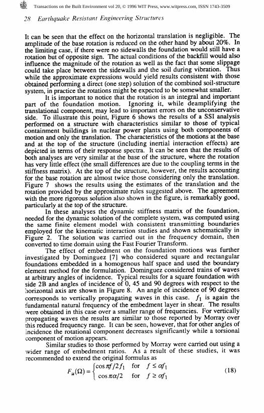
The effect of embedment on the foundation motions was furtherinvestigated by Dominguez [7] who considered square and rectangularfoundations embedded in a homogenous half space and used the boundaryelement method for the formulation. Dominguez considered trains of wavesat arbitrary angles of incidence. Typical results for a square foundation withside 2B and angles of incidence of 0, 45 and 90 degrees with respect to thehorizontal axis are shown in Figure 8. An angle of incidence of 90 degreescorresponds to vertically propagating waves in this case, fi is again thefundamental natural frequency of the embedment layer in shear. The resultswere obtained in this case over a smaller range of frequencies. For verticallypropagating waves the results are similar to those reported by Morray overthis reduced frequency range. It can be seen, however, that for other angles ofincidence the rotational component decreases significantly while a torsionalcomponent of motion appears.
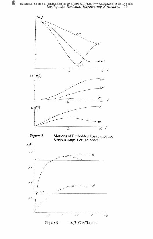
Similar studies to those performed by Morray were carried out using awider range of embedment ratios. As a result of these studies, it wasrecommended to extend the original formulas as
costf/2/i for fzafi
for f>af,
Transactions on the Built Environment vol 20, © 1996 WIT Press, www.witpress.com, ISSN 1743-3509
Earthquake Resistant Engineering Structures 29
Figure 8 Motions of Embedded Foundation forVarious Angels of Incidence
Figure 9 a,/? Coefficients
Transactions on the Built Environment vol 20, © 1996 WIT Press, www.witpress.com, ISSN 1743-3509

30 Earthquake Resistant Engineering Structures
with a and ft functions of the embedment ratio E/R as shown in Figure 9.
4 Foundation Stiffnesses
Using the same finite element model with consistent lateral boundaries shownschematically in Figure 2, Elsabee [6, 8] conducted parametric studiesdetermining the dynamic stiffness matrix of embedded rigid circularfoundations with different ratios of the embedment depth to the radius and ofthe layer thickness to the radius. For each foundation, results were obtainedusing three different finite element meshes with elements of square crosssection and sides equal to one-quarter, one-eighth and one- sixteenth of theradius. The results from these three meshes were then extrapolated (a linearextrapolation with respect to element size) to obtain an improved estimate.
The stiffness matrix for an embedded, rigid, circular foundationconsidering only two degrees of freedom (horizontal translation and rotation)will be of the form
The terms K K K = K^ and K^ will be complex functions of
frequency. It is common to write them in the formK = KQ(l + 2iD)[k + ioQc] (21)
where KQ is the static value (corresponding to zero frequency), D is theinternal soil damping (assumed to be of a linear hysteretic nature), k and care the dynamic stiffness coefficients (functions of frequency) and OQ is adimensionless frequency equal to pR with p as defined in eq. (15). It shouldbe noticed that when there is internal damping, OQ will be complex with this
notation. Alternatively, one can use only the real part of 00, modifyingaccordingly the values of k and c, which would become functions also of D.
Based on his studies Elsabee extended the formulas derived by Kausel[3] for the static stiffness of circular foundations on the surface of a soil layerof finite depth, to account for embedment. The expressions he suggested are
Figure 10 shows the variation of the stiffness coefficients k and c versusfrequency for the K^ and the K^ terms and a foundation with E = R and
H = 3R. The results are compared to those of a surface foundation on a layer
Transactions on the Built Environment vol 20, © 1996 WIT Press, www.witpress.com, ISSN 1743-3509

SYrwcfwr&f
of the same thickness H and those of a circular mat on the surface of ahomogenous half space. When dealing with a layer of finite depth thecoefficient c which represents the loss of energy by radiation of the wavesaway from the foundation will be zero below a threshold frequency which isthe fundamental natural frequency in shear of the stratum for horizontaltranslation and the vertical natural frequency in rocking if Poisson's ratiov 0.3. For larger values of Poisson's ratio it is a frequency intermediatebetween the two. For the half space the term c starts with a nonzero valuefrom the beginning for the horizontal stiffness. It starts however at 0 for therocking term and a surface foundation. The real stiffness coefficient k has anumber of oscillations associated with the natural frequencies when dealingwith a soil layer of finite depth and is much smoother for a deep layer (if thereis some internal soil damping) or for a homogenous half space. It is alsosmoother in rocking than for horizontal translation.
For a surface foundation on a half space the dynamic stiffnesscoefficients k and c corresponding to horizontal translation are essentiallyconstant with values of 1 and 0.6 approximately (the value of c is a functionof Poisson's ratio). The same variations could be used for an embeddedfoundation in a half space but the value of c would increase, depending on theembedment ratio E/R. For E = R it can be seen that c = 0.9. For a finitelayer the value of k would have oscillations as mentioned above and the valueof c would have to be truncated below the threshold frequency. The values ofk and c are functions of frequency for the rocking case. Approximateexpressions for a surface foundation on a half space are
l- 0.2ao for %<2.5
0.5 for % > 2.5
and
(24)
More accurate expressions for these coefficients, function of Poisson'sration were proposed by Veletsos and Verbic (9). One could again use thesame expressions for k in case of an embedded foundation, but the coefficient0.35 in eq. (24) would increase with embedment (to 0.45 or so for E = R).
Novak [10] had proposed an alternative simplified procedure tocompute approximately the dynamic stiffnesses of circular foundationsembedded in a half space. In this approach the stiffness terms are assumed toconsist of the contribution of the base (with a stiffness equal to that of asurface foundation) and the sidewalls (reproduced by a series of frequencydependent springs and dashpots obtained from the study of a rigid diskvibrating in a plane). The values of the springs and dashpots can be expressedin closed form in terms of modified Bessel functions. Studies by Chen [11]have shown that the real part of the stiffnesses (the terms K$k) predicted byNovak's approach tend to be smaller than the results of finite element analysesespecially in rocking. On the other hand the values of the imaginary parts ofthe stiffnesses (the terms #0 0) predicted by Novak's approximation are inexcellent agreement with the finite element results for a half space. They arealso a very good approximation for a foundation embedded in a layer of finitedepth above the threshold frequency. Below this frequency Novak's solution
Transactions on the Built Environment vol 20, © 1996 WIT Press, www.witpress.com, ISSN 1743-3509

ift>3
Figure 10
DYNAMIC STIFFNESS COEFFICIENTS, u = 1/3, 0 = 0.05
Transactions on the Built Environment vol 20, © 1996 WIT Press, www.witpress.com, ISSN 1743-3509

Earthquake Resistant Engineering Structures 33
would predict nonzero values of the imaginary terms, which should be zero.Once the dynamic stiffness matrix of the foundation is known, the
third and final step of the SSI analysis obtaining the response of the structureon a flexible foundation to the motions computed accounting for kinematicinteraction is straightforward particularly when performed in the frequencydomain. Some complications arise, however, when attempting to use moretraditional methods of structural dynamics in the time domain, such as modalanalysis or especially modal spectral analysis. It is particularly important thatthe structural model be able to account for both translational and rotationalmotions for an embedded rigid foundation or for independent, differentmotions of the various contact points for flexible foundations.
The main effects of the inertial interaction, which have beenextensively discussed in the literature, are the modification in the naturalperiod of the structure (an elongation of the period due to the added flexibilityof the foundation) and a change in the effective damping of the system whichis in most cases an increase (when there is radiation damping). Theimportance of these effects depends on the relative stiffness of the structurewith respect to the soil. As embedment increases so do the foundationstiffnesses and therefore the inertial interaction effects tend to decrease inimportance at least in relation to the change in the effective natural period.The effective damping decreases because of the reduced interaction butincreases due to the larger values of the coefficient c.
For any given earthquake record the effect of the change in period canbe beneficial or detrimental depending on the value of the initial period (on arigid base) and the characteristics of the seismic motion (as represented forinstance by the response spectra). For a smoothed design spectrum the effecttends to be beneficial at least for nuclear power plants. The increase ineffective damping, if there is an increase, will always be beneficial.
5 Final Considerations
Soil structure interaction effects are often associated only with the inertialinteraction phenomena (elongation of the effective natural period and changein the effective damping). These are indeed the only effects when consideringthe dynamic response of a structure subjected to external loads applieddirectly on the structure (wind loads, wave loads, or machine vibrations). Forthe seismic case, however, one must also consider kinematic interactioneffects. When dealing with structures on surface foundations the effects of thekinematic interaction tend to be small unless one has very long and rigidfoundations. Inertial interaction effects tend to be then the predominant ones.For embedded foundations, on the other hand, kinematic interaction effectscan become important and much more so than inertial interaction.
The approximate methods discussed in this paper, in combination withthe formulas available in the literature to compute the inertial interactioneffects for an equivalent single degree of freedom system, allow to conductpreliminary analyses and estimate the relative importance and significance ofthe various effects. Because kinematic interaction will result in a seduction inthe amplitudes of the translational motion, which can be significant for deeplyembedded foundations, there has been a controversy about accepting it. Twomistakes which have complicated further the issue are the confusion betweenthe transfer functions for the motions of an embedded foundation (3Dsolution) and the ID solution for the motion at the foundation level in the free
Transactions on the Built Environment vol 20, © 1996 WIT Press, www.witpress.com, ISSN 1743-3509

34 Earthquake Resistant Engineering Structures
field (which has much larger oscillations), and ignoring the rotationalcomponent of motion. It is true on the other hand that the values of thetranslational and rotational components of motion are a function of the angleof incidence of the waves but for soft soils where the effects are important thewaves in the embedment region should be traveling almost vertically.
References
1. Iguchi, M., Seismic Response with Consideration of Both PhaseDifferences of Ground Motion and Soil Structure Interaction,Proceedings of Japan Earthquake Engineering Symposium, 1973.
2. Waas, G., Linear Two Dimensional Analysis of Soil Dynamics Problemsin Semi Infinite Layered Media, Ph D. Dissertation, University ofCalifornia, Berkeley, 1972.
3. Kausel, E., Forced Vibration of Circular Foundations on LayeredMedia, Research Report R74-11, Department of Civil Engineering, M. I.T., 1974.
4. Tassoulas, J. L., Elements for the Numerical Analysis of Wave Motion inLayered Media, Research Report R81-2, Department of CivilEngineering, M. I. T., 1982.
5. Morray, J. P., The Kinematic Interaction Problem of Embedded CircularFoundations, M. S. Thesis, Department of Civil Engineering, M. I. T.,1975.
6. Elsabee, F. and Morray, J. P., Dynamic Behavior of EmbeddedFoundations, Research Report R77-33, Department of CivilEngineering, M. I. T., 1977.
7. Dominguez, J., Response of Embedded Foundations to Traveling Waves,Research Report R78-24, Department of Civil Engineering, M. I. T.,1978.
8. Elsabee, F., Static Stiffness Coefficients for Circular FoundationsEmbedded in an Elastic Medium, M. S. Thesis, Department of CivilEngineering, M. I. T., 1975.
9. Veletsos, A. S. and Verbic, B., Impulse Response Functions for ElasticFoundations, Report No. 5, Department of Civil Engineering, RiceUniversity, 1972.
10. Novak, M., Vibrations of Embedded Footings and Structures, Reprint2029, ASCE National Structural Engineering Meeting, San Francisco,California, 1973.
11. Chen, H.T., Dynamic Stiffness of Uniformly Embedded Foundation,Geotechnical Engineering Report GR84-9, Civil EngineeringDepartment, The University of Texas at Austin, 1984.
Transactions on the Built Environment vol 20, © 1996 WIT Press, www.witpress.com, ISSN 1743-3509