determination of gas-diffusion and interface-mass-transfer ... · diffusion, which is required for...
TRANSCRIPT
Determination of gas-diffusion andinterface-mass-transfer coefficients infracture-heavy oil saturated porous matrixsystemE. Zamanian, M. Hemmati and M. S. Beiranvand
ORIGINAL SCIENTIFIC PAPER
For the modeling and simulation of oil recovery from naturally fractured reservoirs during the gas injectionprocess, an accurate value of the molecular diffusion coefficient (MDC) of gases from a gas filled fractureinto the oil matrix is essential. During the injection of miscible fluids with oil, transport of the injectant andoil are controlled by fracture and matrix properties. Diffusion is a significant-oil recovery mechanismbetween matrix and fracture. However, experimentally determined data concerning to gas transfer betweenfracture-matrix systems by diffusion mechanism are relatively rare.In this study the pressure-decay method is applied to obtain effective molecular diffusion coefficient of CO2
and CH4 in heavy oil saturated porous matrix media at different conditions of temperatures. Gas-diffusionand interface-mass-transfer coefficients are determined by applying a transient-state equilibrium diffusionmodel. The effect of porous media presence on these coefficients has also been investigated.It is expected that the experimental results will be useful in deriving the matrix-fracture transfer function bydiffusion, which is required for simulation of recovery in naturally fractured reservoirs.
Key words: molecular diffusion coefficient, interface-mass-transfer, fracture, porous matrix, heavy oil,fractured reservoir
1. IntroductionA large proportion of the world's proven oil reserves havebeen found in naturally fractured reservoirs (NFRs). Thetarget oil in NFRs exists in rock matrix. During the injec-tion of tertiary recovery materials that are miscible withmatrix oil, i.e., hydrocarbon solvents, alcohols, CO2,CH4, etc., fracture network creates the path for the in-jected solvent to bypass and leave the unswept oil zonesin the matrix. Significant amount of oil can be recoveredfrom this upswept bypassed zone by maximizing the sub-sequent crossflow or mass transfer between fracture andmedia. In this type of reservoirs, the transport of theinjectant and the oil is controlled by fracture and matrixproperties. Diffusion is a significant-oil recovery mecha-nism for mass transfer between matrix and fracture.Similar processes can be encountered during the seques-tration of greenhouse gases, and the transport of contam-inants in subsurface reservoirs. More over, in heavy oilrecovery from naturally fractured reservoir by miscibleEOR technique, like miscible gas flooding the role of dif-fusion mechanism in improving oil recovery is crucial.13
For the heavy oil NFRs, the role of diffusion process inmiscible oil recovery methods such as miscible gas flood-ing will be stronger due to very high viscosities of them.Therefore an accurate value of the molecular diffusioncoefficient (MDC) of gases from the gas filled fracture intothe heavy oil saturated matrix is essential for calculatingthe rate of gas dissolution in heavy oils.
However, experimentally determined data concerningto gas transfer between fracture-matrix systems by diffu-
sion mechanism are relatively rare in the open literatureand most of the published values of diffusivity data arerelated to the bulk systems, in absence of the porousmedia.
Diffusion within porous matrix has been studied sincethe early years of the 20th century, especially in homoge-neous media with intergranular porosity. Some stud-ies7,11 focused on finding the relationship between themolecular diffusion, tortuosity, formation resistivity fac-tor and effective matrix MDC. However, some others wereinterested in measuring the MDC utilizing indirect meth-ods. For example, one common applied methodology isto establish a gas flow at one end of a liquid saturatedmatrix block and measure the concentration changes inthe resulting current flow.12 In such a system it is very dif-ficult to measure the concentration variations in the cur-rent flow, because changes are generally very small.Renner8 measured diffusion coefficients of hydrocarbongases in consolidated porous media saturated with dec-ane and brine at pressures up to 6 MPa. He developed acorrelation as a function of liquid viscosity andthermo-physical properties of the diffusing gases for pre-dicting diffusion coefficient. However, in this studydiffusivity of light gases into heavy oil is correlated as afunction of temperature, oil viscosity and molecularweight of the diffusing gases.
Amongst all experimental methods developed to mea-sure gas diffusivity in liquids, pressure-decay techniqueused first by Riazi9 has attracted much attention due toits simplicity and robustness of the approach. He mea-
NAFTA 63 (11-12) 351-358 (2012) 351
sured methane diffusivity in liquid pentane by recordingboth the rate of pressure drop and the interface move-ment of gas-liquid due to pentane swelling. Later, Zhanget al.14 used this method for dilute solutions of a solventgas in heavy oil. They developed a simplified experimen-tal procedure and mathematical solution to relate therate of pressure decline to diffusivity. Civan and Rasmus-sen3,4 developed a mathematical model for further studyon the experimental work of Zhang et al.14 in order to es-timate the gas diffusion coefficient. They ended up withtwo models including; equilibrium and non-equilibriumones. The non-equilibrium model accounted for the de-lay in gas transport in the liquid phase. Though, theirwork was limited to the bulk system, without a proper in-vestigation of the porous media effect on the diffusion.
In the present research, a comprehensive experimentalinvestigation on the effective molecular diffusion deter-mination of CO2 and CH4-heavy oil systems in homoge-neous porous matrix was undertaken. In particular,glass beads of well-defined size in the range of 0.0177 -0.0297 cm and porosity of 0.43 were used. The so-calledpressure decay method was applied to measure the mo-lecular diffusivity of gases in heavy oil. This paper alsopresents a methodology that can differentiate betweenthe various stages in the diffusion process.
2. ExperimentsA pressure-decay experimental setup was constructed tomeasure the effective MDC of pure CO2 and CH4 inpacked glass beads saturated with heavy oil. The heavyoil components and related compositions were deter-mined previously, using gas chromatography techniqueare shown in Table 1.
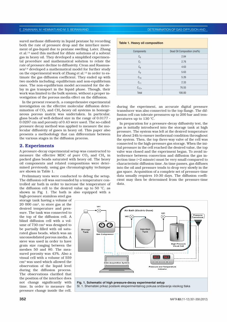
Preliminary tests were conducted to debug the setup.The diffusion cell was surrounded by a temperature con-trolled air bath in order to increase the temperature ofthe diffusion cell to the desired value up to 50 °C, asshown in Fig. 1. The bath is also equipped with ahigh-pressure stainless steel gasstorage tank having a volume of20 000 cm3, to store gas at thedesired temperature and pres-sure. The tank was connected tothe top of the diffusion cell. Ablind diffusion cell with a vol-ume of 730 cm3 was designed tobe partially filled with oil satu-rated glass beads, which was anunconsolidated porous media. Asieve was used in order to havegrain size ranging between themeshes 50 and 80. The mea-sured porosity was 43%. Also avisual cell with a volume of 559cm3 was used which allowed theobservation of the liquid levelduring the diffusion process.The observations clarified thatthe position of the interface doesnot change significantly withtime. In order to measure thepressure change inside the cell,
during the experiment, an accurate digital pressuretransducer was also connected to the top flange. The dif-fusion cell can tolerate pressures up to 200 bar and tem-peratures up to 130 °C.
In preparation for a pressure-decay diffusivity test, thegas is initially introduced into the storage tank at highpressure. The system was left at the desired temperaturefor about 24h to ensure isothermal condition throughoutthe system. Then, the top three-way valve of the cell wasconnected to the high-pressure gas storage. When the ini-tial pressure in the cell reached the desired value, the topvalve was closed and the experiment began. To avoid in-terference between convection and diffusion the gas in-jection time (~2 minute) must be very small compared tocharacteristic diffusion time. As time passes, gas diffusesinto the oil and pressure tends to drop very slowly in thegas space. Acquisition of a complete set of pressure-timedata usually requires 10-30 days. The diffusion coeffi-cient may then be determined from the pressure-timedata.
352 NAFTA 63 (11-12) 351-358 (2012)
E. ZAMANIAN, M. HEMMATI AND M. S. BEIRANVAND DETERMINATION OF GAS-DIFFUSION AND...
Components Dead Oil Composition (mol%)
C6 2.84
C7 2.76
C8 4.63
C9 5.63
C10 5.26
C11 2.33
C12+ 76.55
Total 100.00
Table 1. Heavy oil composition
Fig. 1. Schematic of high pressure-decay experimental setupSl. 1. Shematski prikaz postavki eksperimentalnog pokusa sni�avanja visokog tlaka

3.Theory
3.1 Mass transfer Model
When a gas is injected into a pressure cell containingheavy oil sample, direct contact between the injected gasand heavy oil takes place at their interface. Subsequently,the gas is gradually dissolved in the heavy oil until the lat-ter is completely saturated with the former. A schematicdiagram of the gas-heavy oil system is shown in Fig.2,where the gas-heavy oil interface is located at x = 0 andthe bottom of the pressure cell is located at x=L.
Dissolution of gas into the heavy oil is modeled by as-suming that the rate of gas leaving the supply cell is equalto the rate of gas dissolution in the oil. This is valid be-cause theoretically, no gas accumulates in the gas cap.Thus, knowing the initial pressure of the supply cell tankand subtracting the measured pressures from it, one canhave the amount of gas transfer from the supply cell tothe diffusion cell verses time. As it is explained in the ex-perimental part, this transfer happens only when there isgas demand in the diffusion cell. As a result of dissolu-tion, this gas demand diminishes when the liquid col-umn concentration is equal to its saturationconcentration. Therefore, equation (1) models the gasbalance in the supply cell. The mass balance equation forthe gas in the supply cell is:
M h
RT
p
z
p
zQ
g 0
0
��
���
�
��� , t>0 (1)
where p and T are the pressure and temperature of thegas, R is the universal gas constant; z=z(p,T) representsthe real-gas deviation factor, correlated empirically as afunction of pressure and temperature and Q denotes thecumulative mass of the dissolved gas in the liquid phaseper unit cross-sectional area of the gas/liquid interface.
Civan (2001) derived an alternative expression for Q asfollow:
� �� Q t C x t C dx L Cx
Lt C d
x
L
L
� ���
����
�
���
�����
����� , ,0 0
0
1
0
(2)
where L is the height of the liquid column.
By applying the continuity equation and the Fick's law,the molecular diffusion process can be described by anunsteady state condition and one-dimensional system isrepresented by1:
�
�
�
�
C
tD
c
xeff
2
2(3)
where C(x,t) is the molar concentration of the gas in theheavy oil, x is the distance from the bottom of the pres-sure cell, t is time and Deff is the effective MDC of gas inheavy oil, assuming that it is independent of gas concen-tration.
The following boundary and initial conditions can beconsidered for concentration:
• The solvent mass transfer flux at the interface is as-sumed to be proportional to the difference between thesaturation concentration under the equilibrium pres-sure and the existing concentration at the interface:
� � �DC
xC p C x t
x
sat eq
�
�
�0
, , t >0 (4)
• Oil sample is a dead oil and the initial condition is:
�C x tt
,0
, 0� �x L (5)
• The infinite-distanced condition is:
�C x tx
,��
, t � 0 (6)
• The sealed tank bottom condition is:
�
�
C
xx L
0 , t >0 (7)
The dimensionless form of the equations can be orga-nized by introducing the following dimensionless param-eters:
�
�C
C x t
C pD
sat eq
,
Xx
LD t
t
LD
D2k
k
LD
D (8)
Here, kD is referred to as the mass transfer Biot num-ber.
The dimensionless mass-accumulation function can beexpressed as
� �Q t C x t dxD D D D D D� ,0
1
(9)
Eq. (1) can also be written in the non-dimensional form
� � �
M h
RTL C p
p
z
p
zQ t t
g
sat eq
D D0
0
0��
��
�
�� �, (10)
Eq. (10) can be applied to any conveniently selected ref-erence pressure value pr measured at a dimensionlesstime tDr to obtain
DETERMINATION OF GAS-DIFFUSION AND... E. ZAMANIAN, M. HEMMATI AND M. S. BEIRANVAND
NAFTA 63 (11-12) 351-358 (2012) 353
Fig. 2. Schematic of the PVT cellSl. 2. Shematski prikaz PVT èelije

� � �
M h
RTL C p
p
z
p
zQ t t
g
sat eq
r
r
D Dr0
0
0��
��
�
�� �, (11)
Choosing the reference pressure equal to equilibriumpressure, the following expression will be obtained bycombination of Eqs. (10) and (11)4:
�
� �
Q t
p
z
p t
z t
p
z
p
z
D D
D
D
eq
eq
��
��
�
��
��
��
�
��
0
0
0
0
(12)
All the parameters for determining the right hand sideof Eq. (12) are known or can be calculated from our ex-perimental data. The left hand side of Eq. (12) is foundby Civan4 method. The forward solutions of Eqs. (2) to(6) for both finite and infinite acting was given as follows:
• Short-time (Semi-Infinite) Solution, (L � �).
The analytical solution for semi-infinite regions is givenby the following equation:
� � �Q tk
k t erfc k t kt
D
ST
D
D
D D D D DD � �
11 22exp
�(13)
When tD is very large, the short-time approximation ofEq. (13) approaches the asymptote4:
�Q tt
kD
ST
DD
D
� �21
�, k tD D � � (14)
In practice the large-time behavior of the short-time ap-proximation applies to some midrange of the overall timevariation. Thus, when QD is plotted against tD , we might
expect some midrange portion of the curve to be nearlyparallel to, or coincident with the straight -line asymptoteby Eq. (14).
• Long-Time (Finite-Length) Solution
The analytical solution for the finite-acting model is ex-pressed in the following dimensionless form:
� ��
�Q t tD Dm
m m mm
m D ��
�
�
�1 42 2
2
1
2sin
sinexp
�
� � �� (15)
where �mdenotes the roots of
� �m m Dktan (16)
When the time tD is large, only the leading term in theinfinite-series solution is significant, and Eq. (15) can besimplified as:
� � �Q t Q tD D m D � �1 1 12� �exp (17)
where
� ��
Q1 1
21
1 1 1
4
2 2�
�
� � ��
�
sin
sin(18)
This is known as long-time approximation. The param-eter �1 is the smallest positive root of the transcendentalequation � �1 1tan kD. The upper bound � �1 2 / cor-responds to kD � �, which in turn corresponds to thecase for the surface Diriclet-type boundary condition
which its concentration is equal to equilibrium condi-tion. The natural logarithm of Eq. (17) leads to the re-sult4:
�� �� ln ln1 1 12� Q t Q tD
LT
D m D� � (19)
Thus, plotting the natural logarithm of �� ln 1�Q tD
LT
D
against tD produces a straight-line curve. Using thismethod, the two unknown coefficients Deff and k can beextracted from a given set of pressure-decline data.
4. Experimental Results anddiscussions
The measured data for four pressure-decay runs areplotted in Fig. 3. Fig. 3 includes the data related to 4 runsin the presence of the porous media and in the Bulk sys-tem (in the absence of the Porous medium). The objectiveis to interpret experimental data and find the values ofdiffusion coefficient D and interface-mass-transfer coeffi-cient k.
4.1. Analysis of the Asymptotic Long-TimeBehavior for the short Time.
The straight-line character of the curves for asymptoticlong-time behavior for the short time solution on QD(tD)versus t plots (see Fig. 4 to 7) suggests a systematic
method for extracting the diffusion coefficint D and theinterface-film coefficient k values from the data associ-ated with a given physical experiment. By means of Eq.(14), this relation can be expressed as
�Q t a b tD D ST ST� � (20)
in which the intercept and slope of the straight line aregiven by
aK
bL
DST
D
ST 1 2
,�
(21)
Therefore, the diffusion coefficient D and inter-face-mass-transfer coefficient k can be calculated as fol-lows:
DL bST
� 2 2
4(22)
354 NAFTA 63 (11-12) 351-358 (2012)
E. ZAMANIAN, M. HEMMATI AND M. S. BEIRANVAND DETERMINATION OF GAS-DIFFUSION AND...
Fig. 3. Pressure-decay data for the four different runs in thepresent and absent of porous media
Sl. 3. Podaci o padu tlaka za èetiri izvoðenja uz postojanje inepostojanje poroznog medija

DETERMINATION OF GAS-DIFFUSION AND... E. ZAMANIAN, M. HEMMATI AND M. S. BEIRANVAND
NAFTA 63 (11-12) 351-358 (2012) 355
Parameters Run 1 Run 2 Run 3 Run 4
Solute CO2 CH4 CO2 CO2
System Porous Media Porous Media Porous Media Bulk
T (°C) 25 25 50 50
pi (kPa) 545 0 539 0 544 0 568 0
aST 0.107 89 0.14 0.062 7 0.090 5
bST (day-1) 0.013 4 0.020 4 0.949 5 1.273 9
aLT 0.393 88 1.396 8 0.543 5 0.876 9
bLT (day-1) 0.000 192 0.000 11 0.372 0.573 0
�1 2.127 3 2.280 9 2.275 7 2.517 5
D × 109(m2/s) (Short-Time) 13.26 30.88 44.68 226.8
D × 109(m2/s) (Long-Time) 9.195 0.2194 10.78 37.05
k × 107 (m/s) (Short-Time) 17.77 29.39 94.90 202.1
k × 107 (m/s) (Long-Time) 4.19 0.031 9 3.846 5.416
Table 2. Experimental pressure-decay results, diffusivity and mass transfer coefficient
Fig. 4. QD vs t1/2 regression of the CO2/heavy oil data inthe porous matrix system, short-time approximation(T=25 °C & p=5 450 kPa)
Sl. 4. QD nasuprot t1/2 regresija, podaci CO2/teška nafta usustavu poroznog matriksa, kratkoroèna aproksimacija(T=25 °C & p=5 450 kPa)
Fig. 5. QD vs t1/2 regression of the CH4/heavy oil data inthe porous matrix system, short-time approximation(T=25 °C & p=5 390 kPa
Sl. 5. QD nasuprot t1/2 regresija, podaci CO4/teška nafta usustavu poroznog matriksa, kratkoroèna aproksimacija(T=25 °C & p=5 390 kPa)
Fig. 6. QD vs t1/2 regression of the CO2/heavy oil data in theporous matrix system, short-time approximation(T=50 °C & p=5 440 kPa)
Sl. 6. QD nasuprot t1/2 regresija, podaci CO2/teška nafta usustavu poroznog matriksa, kratkoroèna aproksimacija(T=50 °C & p=5 440 kPa)
Fig. 7. QD vs t1/2 regression of the CO2/heavy oil data in thebulk system, short-time approximation (T=50 °C &p=5470 kPa)
Sl. 7. QD nasuprot t1/2 regresija, podaci CO2/teška nafta usustavu poroznog matriksa, kratkoroèna aproksimacija(T=50 °C & p=5 470 kPa)

kD
Lk
D
LaD
ST
(23)
The coefficients obtained by this approximtion aregiven in Table. 2.
4.2 Analysis for Large Times
The striaght-line character of the curves for large timeson semilog plots (see Fig. 8 to 10) suggests a systematicmethod for extracting the values of the diffusion coeffi-cient D and the interface-film coefficient k from the dataassociated with a given physical experiment. Thelarge-time approximation Eq. (17) is expressed in termsof the actual time t. The experimental data can be corre-lated with a stright line by means of a regression analysisin the form of
� log10 1� � �Q a b tD LT LT (24)
where the y-axis intercept and the slope of the line,measured per unit time, are, respectively
�� � ��
a QLT
LT� ��
!"
#$%
log logsin
sin0 1
21
1
4
1 2 1 2�
�
� � �(25)
bD
LLT 0 4343 1
2
2. � (26)
Eq. (25) allows determination of �1and thus kD by virtueof the relation � �1 1tan kDgiven by Eq. (16). Conse-quently, the mass-transfer kD is determined entirely bythe y-axis intercept.
Having �1, the diffusion coefficient D is found from Eq.(26):
Db LLT
2
120 4343. �
(27)
kD is calculated by Eq. (16):
kD � �1 1tan (28)
Finally, the interface film mass-transfer coefficient k
can be determined:
356 NAFTA 63 (11-12) 351-358 (2012)
E. ZAMANIAN, M. HEMMATI AND M. S. BEIRANVAND DETERMINATION OF GAS-DIFFUSION AND...
Fig. 8. ln(1-QD) vs t plot of the CO2/heavy oil data in theporous matrix system, the long time behavior (T=25°C and p=5 450 kPa)
Sl. 8. ln (1-QD) nasuprot t za podatke CO2/teška nafta usustavu poroznog matriksa, ponašanje kroz dugivremenski period (T=25 °C & p=5 450 kPa)
Fig. 9. ln(1-QD) vs t plot of the CH4/heavy oil data in theporous matrix system, the long time behavior (T=25°C and p=5 390 kPa)
Sl. 9. ln(1-QD) nasuprot t za podatke CH4/teška nafta u sustavuporoznog matriksa, ponašanje kroz dugi vremenskiperiod (T=25 °C & p=5 390 kPa)
Fig. 10. ln(1-QD) vs t plot of the CO2/heavy oil data in theporous matrix system, the long time behavior (T=50°C and p=5 440 kPa)
Sl. 10. ln(1-QD) nasuprot t za podatke CO2/teška nafta u sustavuporoznog matriksa, ponašanje kroz dugi vremenskiperiod (T=50 °C & p=5 440 kPa)
Fig. 11. ln(1-QD) vs t plot of the CO2/ heavy oil in the bulksystem, the long time behavior (T=50 °C andp=5 680 KPa)
Sl. 11. ln(1-QD) nasuprot t za podatke CO2/teška nafta u sustavuporoznog matriksa, ponašanje kroz dugi vremenskiperiod (T=50 °C & p=5 680 kPa).

kD
LkD (29)
The diffusivity coefficient and interface mass transfercoefficient obtained by this method are given in Table. 2.The result indicates that the short time diffusivity ishigher than long time values and also the rate of masstransfer will be decreased in long time.
The results in Table 2 also indicate that the moleculardiffusion in the presence of the porous medium was lessthan that in its absence. This is due to the system's poreinterconnections, known as the tortuosity which directlyaffects the path movement of the gas molecules and theeffective contact area of the gas and heavy oil which isequal to the area times porosity (i.e.; Aeffective=A·&). Com-parison of pressure decay trends in both the bulk andporous systems indicate that the rate of pressure decay islowered and the necessary time for the equilibrium pres-sure is enhanced in the porous systems, as shown in Fig-ure 3. This means that in the porous media bothsolubility and diffusivity are decreased comparig withbulk system. Also at the same temperature the difusivityof carbon dioxide had relatively the same order as meth-ane diffusivity during infinite period, while at the longtime the diffusivity of CO2 was more than that of meth-ane. That could be due the fact that as the molecular sim-ilarity increased, the molecular diffusivity and thesolubility at the final equilibrium state of the experimentalso enhanced. Therefore, the resulting diffusivity ofcarbone dioxide would be enhanced because of its highermolecular weight than methane.
Furthermore, by comparison the results of runs 1 and3 experiments (Figure 3) one can observe the effect oftemperature on diffusion process. They showed that asthe temperature increased, the rate of pressure decay en-hanced and final equilibrium pressure lowered. Thismeant that at higher temperatures both solubility anddiffusivity increased. In other words, more gas at higherrates dissolved into heavy crudes under such conditions.
5. ConclusionA high pressure experimental setup is designed and con-structed to measure the effective molecular diffusion ofmethane and carbon dioxide between a gas filled fractureand heavy oil saturared matrix system at desired condi-tions. Various experimental runs at different conditionswere performed. The molecular diffusion coefficients aredetermined using a transient-state equilibrium diffusionmodel. Short-time and long-time molecular diffusion co-efficient and the mass transfer coefficient were deter-mined. The result shows that diffusivity and masstransfer coefficient of methane are less than that of car-bon dioxide, so the injection of CO2 woud be more effec-tive than CH4. Also, the presence of porous media willconsiderably decelerate the difusion process and conse-quently decrease the gas diffusivity. Moreover, it was ob-served that temperature has a direct effect on the bothsolubility and diffiusivity of the gases, so that as the tem-perature increased the rate of dissolution of the gas inheavy oil through diffusion procees was also increased.
Finally, these result of this work will be useful incomposotional simulation and modeling mass transfer
into matrix during solvent injection in fractured andheavy oil reservoirs.
6. NomenclaturesA Cross sectiononal area of the cell (cm2)
C(x,t) Gas concentration in oil saturated porous media(mol/cm3)
Csat(peq) Saturation concentration of the gas in the oil under theequilibrium pressure (mol/cm3)
Deff Effective molecular diffusion coefficient (m2/s)
D0 Pre-exponential factor (m2/s)
Ea Activation energy required for diffusion (cal/mol)
h Height of the gas in the cell (cm)
k Interface mass-transfer coefficient (m/s)
p(t) peq Measured and equilibrium pressures, respectively (kPa)
Q Cumulative gas mass, per unit cross section area,disolved in th liquid phase (kg/m2)
R Universal Gas constant (8314 kPa.cm3/mol.K) or(1.987cal/mol.K)
t Time (s)
T Temperature (°C or K)
V Volume of the gas in the vessel (cm3)
n Number of time series, t=ti , i=1,2,…,n
x Position along diffusion vessel (cm)
L Height of the oil in the vessel (cm)
z Gas deviation compressibility factor
7. Greek symbols� Roots of Eq. 25, Dimensionless
8. SubscriptsD Dimensionless
DETERMINATION OF GAS-DIFFUSION AND... E. ZAMANIAN, M. HEMMATI AND M. S. BEIRANVAND
NAFTA 63 (11-12) 351-358 (2012) 357
9. References1. Bird, R.B.; Stewart, W.E.; Lightfoot, E.N.; Transport Phenomena. Wiley, New
York, 1960.
2. Civan, F., Rasmussen, M. L. Accurate measurement of gas diffusivity in oil andbrine under reservoir conditions. SPE Production Operations SymposiumProceedings. 2001.
3. Civan, F., Rasmussen, M. L. Analysis and interpretation of gas diffusion inquiescent reservoir, drilling and completion fluids: equilibrium vs. non-equi-librium models. Proceedings - SPE Annual Technical Conference and Exhibi-tion. 2003.
4. Civan, F., Rasmussen, M.L., 2006. Determination of gas-Diffusion and Inter-face-Mass-Transfer Coefficients for Quiescent Reservoir Liquids. SPE 84072,Tulsa, Oklahoma.
5. Crank,J.; The Mathematics of Diffusion. Oxford U. Press, London (1975).
6. Mason E.A. and Malinauskas A.P.; Gas transport in porous media: Thedusty-Gas Model. Elsevier, pp:20-24, 1983.
7. Perkins, T. K. and Johnston, O. C.; A Review of Diffusion and Dispersion inPorous Media. SPEJ, 77-91, 1963.
8. Renner.T.A. Measurment and Correlatin of diffusion coefficients for co2 andrich gas application. SPE. Res . Eng ,517-523,May, 1988.
9. Riazi, M.R. A new method for experimental measurement of diffusion coeffi-cients in reservoir fluids. J. Pet. Sci. Eng. 14 (3-4): 235-250, 1988.
10. Roopa, I., Dowe, R. A. Vapex-Gravity-assisted Film Drainage for Heavy OilRecovery. Pet. Sci and Tech. 25, pp. 645-658, 2007.
11. Somerton, W.H. Thermal Properties and Temperature Related Behavior ofRock/Fluid Systems. Elsevier, Amsterdam, 1992.
12. Thomas, L. K.; Dixon T. N., and Pierson R. G. Ekofisk Nitrogen Injection. Pa-per SPE 19839 presented at the Annual Technical Conference and Exhibition,San Antonio, Texas, Oct,1989.
13. Trivedi, J., Babadagli, T.: Experimental and numerical modeling of the masstransfer between rock matrix and fracture. Chemical Engineering Journal 146(2009) 194-204
14. Zhang, Y.; Hyndman, C.L. and Maini, B. Measurement of gas diffusivity inheavy oils. J. Pet. Sci. Eng. 25 (1-2): 37-47, 2000.
�
Authors:
*Ehsan Zamanian, Petroleum Engineering Department, Amirkabir Univer-sity of Technology, Tehran, Iran, Research Institution of Petroleum Industry(R.I.P.I.)-Polymer Division
Mahmoud Hemmati, Research Institution of Petroleum Industry(R.I.P.I.)-Polymer Division
Mahmoud Safar Beiranvand, Institute of Petroleum Engineering, Col-lege of Engineering, University of Tehran, Tehran, Iran
*Corresponding author: Ehsan Zamanian, AmirKabir University of Technol-ogy, Dept. of Petroleum Engineering, Tehran, Iran, mobile: +989166070369,[email protected]
358 NAFTA 63 (11-12) 351-358 (2012)
E. ZAMANIAN, M. HEMMATI AND M. S. BEIRANVAND DETERMINATION OF GAS-DIFFUSION AND...