determination of explosion characteristics of dust cloudsbase.iepi.com.cn/download/standards/cen/en...
TRANSCRIPT

BRITISH STANDARD
BS EN 14034-2:2006Determination of explosion characteristics of dust clouds —
Part 2: Determination of the maximum rate of explosion pressure rise (dp/dt)max of dust clouds
The European Standard EN 14034-2:2006 has the status of a British Standard
ICS 13.230
�������������� ���������������������������������������������������

BS EN 14034-2:2006
This British Standard was published under the authority of the Standards Policy and Strategy Committee on 30 June 2006
© BSI 2006
ISBN 0 580 48679 6
National foreword
This British Standard is the official English language version of EN 14034-2:2006.
The UK participation in its preparation was entrusted to Technical Committee FSH/23, Fire precautions in industrial and chemical plant, which has the responsibility to:
A list of organizations represented on this committee can be obtained on request to its secretary.
Cross-references
The British Standards which implement international or European publications referred to in this document may be found in the BSI Catalogue under the section entitled “International Standards Correspondence Index”, or by using the “Search” facility of the BSI Electronic Catalogue or of British Standards Online.
This publication does not purport to include all the necessary provisions of a contract. Users are responsible for its correct application.
Compliance with a British Standard does not of itself confer immunity from legal obligations.
— aid enquirers to understand the text;
— present to the responsible international/European committee any enquiries on the interpretation, or proposals for change, and keep UK interests informed;
— monitor related international and European developments and promulgate them in the UK.
Summary of pages
This document comprises a front cover, an inside front cover, the EN title page, pages 2 to 26, an inside back cover and a back cover.
The BSI copyright notice displayed in this document indicates when the document was last issued.
Amendments issued since publication
Amd. No. Date Comments

EUROPEAN STANDARD
NORME EUROPÉENNE
EUROPÄISCHE NORM
EN 14034-2
May 2006
ICS 13.230
English Version
Determination of explosion characteristics of dust clouds - Part 2: Determination of the maximum rate of explosion pressure rise
(dp/dt)max of dust clouds
Détermination des caractéristiques d'explosion des nuages de poussière - Partie 2: Détermination de la vitesse
maximale de montée en pression d'explosion (dp/dt)max des nuages de poussière
Bestimmung der Explosionskenngrößen von Staub/Luft-Gemischen - Teil 2: Bestimmung des maximalen zeitlichen
Druckanstiegs (dp/dt)max von Staub/Luft-Gemischen
This European Standard was approved by CEN on 20 April 2006. CEN members are bound to comply with the CEN/CENELEC Internal Regulations which stipulate the conditions for giving this European Standard the status of a national standard without any alteration. Up-to-date lists and bibliographical references concerning such national standards may be obtained on application to the Central Secretariat or to any CEN member. This European Standard exists in three official versions (English, French, German). A version in any other language made by translation under the responsibility of a CEN member into its own language and notified to the Central Secretariat has the same status as the official versions. CEN members are the national standards bodies of Austria, Belgium, Cyprus, Czech Republic, Denmark, Estonia, Finland, France, Germany, Greece, Hungary, Iceland, Ireland, Italy, Latvia, Lithuania, Luxembourg, Malta, Netherlands, Norway, Poland, Portugal, Romania, Slovakia, Slovenia, Spain, Sweden, Switzerland and United Kingdom.
EUROPEAN COMMITTEE FOR STANDARDIZATION C O M I T É E U R O P É E N D E N O R M A L I S A T I O N E U R O P Ä I S C H E S K O M I T E E F Ü R N O R M U N G
Management Centre: rue de Stassart, 36 B-1050 Brussels
© 2006 CEN All rights of exploitation in any form and by any means reserved worldwide for CEN national Members.
Ref. No. EN 14034-2:2006: E

EN 14034-2:2006 (E)
2
Contents Page
Foreword..............................................................................................................................................................4 Introduction .........................................................................................................................................................5 1 Scope ......................................................................................................................................................6 2 Normative references ............................................................................................................................6 3 Terms and definitions ...........................................................................................................................6 4 Test apparatus .......................................................................................................................................7 4.1 General....................................................................................................................................................7 4.2 Explosion vessel....................................................................................................................................7 4.3 Dust dispersion system (dust container, fast acting valve, connecting tube, dust
disperser)................................................................................................................................................8 4.4 Ignition source .................................................................................................................................... 10 4.5 Control unit.......................................................................................................................................... 11 4.6 Pressure measuring system.............................................................................................................. 11 5 Dust sample......................................................................................................................................... 11 6 Test procedure.................................................................................................................................... 11 7 Calibration and verification ............................................................................................................... 14 7.1 Calibration ........................................................................................................................................... 14 7.2 Verification .......................................................................................................................................... 14 8 Safety precautions / instructions...................................................................................................... 15 9 Alternative test equipment / procedures.......................................................................................... 15 10 Test report ........................................................................................................................................... 16 Annex A (normative) Electro Pneumatic Valve ............................................................................................. 17 Annex B (normative) Dust dispenser with 5 mm holes................................................................................ 19 Annex C (normative) 20 l sphere .................................................................................................................... 22 C.1 General................................................................................................................................................. 22 C.2 Test apparatus .................................................................................................................................... 22 C.3 Test conditions ................................................................................................................................... 23 C.4 Test procedure.................................................................................................................................... 23 C.5 Calculation of (dp/dt)max, 20 l, Kmax and KSt ......................................................................................... 24 Annex ZA (informative) Relationship between this European Standard and the
Essential Requirements of EU Directive 94/9/EC............................................................ 25 Bibliography..................................................................................................................................................... 26
Figures
Figure 1 — 1 m³ vessel (schematic)................................................................................................................. 8 Figure 2 — Dust container with blasting cap activated valve as commonly used for explosion
suppression (schematic; it is commercially available) .......................................................................... 9 Figure 3 — Location of the 6 mm holes in the dust disperser.................................................................... 10 Figure 4 — Dust dispersion and pressure-time curve ................................................................................. 13 Figure 5 — Determination of the maximum rate of explosion pressure rise (dp/dt)max............................ 14 Figure A.1 — Electro Pneumatic Valve (schematic)..................................................................................... 17

EN 14034-2:2006 (E)
3
Figure A.2 — Discharge characteristic of dust dispersers (without dust) .................................................18 Figure B.1 — Location of the 5 mm holes in the dust disperser .................................................................20 Figure B.2 — Rebound nozzle.........................................................................................................................21 Figure B.3 — Dispersion cup ..........................................................................................................................21 Figure C.1 — Test equipment 20 l sphere (schematic).................................................................................23
Tables
Table 1 — Maximum permissible deviations SEQ ........................................................................................15 Table ZA.1 — Correspondence between this European Standard and Directive 94/9/EC........................25

EN 14034-2:2006 (E)
4
Foreword
This document (EN 14034-2:2006) has been prepared by Technical Committee CEN/TC 305 “Potentially explosive atmospheres - Explosion prevention and protection”, the secretariat of which is held by DIN.
This European Standard shall be given the status of a national standard, either by publication of an identical text or by endorsement, at the latest by November 2006, and conflicting national standards shall be withdrawn at the latest by November 2006.
This document has been prepared under a mandate given to CEN by the European Commission and the European Free Trade Association, and supports essential requirements of EU Directives.
For relationship with the EU Directive 94/9/EC, see informative Annex ZA, which is an integral part of this document.
This European Standard is one of a series of standards as listed below:
EN 14034 "Determination of explosion characteristics of dust clouds"
– Part 1: Determination of the maximum explosion pressure pmax of dust clouds;
– Part 2: Determination of the maximum rate of explosion pressure rise (dp/dt)max of dust clouds;
– Part 3: Determination of the lower explosion limit LEL of dust clouds;
– Part 4: Determination of the limiting oxygen concentration LOC of dust clouds.
According to the CEN/CENELEC Internal Regulations, the national standards organizations of the following countries are bound to implement this European Standard: Austria, Belgium, Cyprus, Czech Republic, Denmark, Estonia, Finland, France, Germany, Greece, Hungary, Iceland, Ireland, Italy, Latvia, Lithuania, Luxembourg, Malta, Netherlands, Norway, Poland, Portugal, Romania, Slovakia, Slovenia, Spain, Sweden, Switzerland and United Kingdom.
EN 14034-2:2006 (E)
5
Introduction
This European Standard specifies a method for experimental determination of the maximum rate of explosion pressure rise of dust clouds. The maximum rate of explosion pressure rise is the maximum value of the pressure rise per unit time during explosions of explosive atmospheres in the explosion range of a combustible dust in a closed vessel. The measurement of the maximum rate of explosion pressure rise forms the basis for explosion protection by design and construction of equipment, protective systems and components to reduce the explosion effects.
Therefore this document gives added values to the following clauses of the EU directives:
Directive 94/9/EC of the European Parliament and the Council of March 23, 1994 on the approximation of the laws of the member states concerning equipment and protective systems intended for use in potentially explosive atmospheres.
Annex II, Clause 1.0.1
Directive 98/37/EC of the European Parliament and the Council of June 22, 1998 on the approximation of the laws of the member states relating to machinery
Annex I, Clause 1.5.7

EN 14034-2:2006 (E)
6
1 Scope
This standard describes a test method for the determination of the maximum rate of explosion pressure rise of dust clouds in a closed vessel under defined initial conditions of pressure and temperature.
This method is not suitable for use with recognised explosives, like gunpowder and dynamite, explosives which do not require oxygen for combustion, pyrophoric substances, or substances or mixtures of substances which may under some circumstances behave in a similar manner. Where any doubt exists about the existence of hazard due to explosive properties, expert advice should be sought.
2 Normative references
The following referenced documents are indispensable for the application of this document. For dated references, only the edition cited applies. For undated references, the latest edition of the referenced document (including any amendments) applies.
EN 14460, Explosion resistant equipment
3 Terms and definitions
For the purposes of this document, the following terms and definitions apply.
3.1 dust small solid particles in the atmosphere which settle out under their own weight, but which may remain suspended in air for some time (includes dust and grit, as defined in ISO 4225)
NOTE Generally maximum particle size will not exceed 500 µm.
3.2 combustible dust dust able to undergo an exothermic reaction with air when ignited
NOTE The terms “flammable” and “combustible” are used synonymously.
3.3 explosion pressure pex highest overpressure occurring during an explosion of a dust cloud in a closed vessel
3.4 explosive atmosphere mixture with air, under atmospheric conditions, of flammable (combustible) substances in the form of gases, vapours, mists or dusts, in which, after ignition has occurred, combustion spreads to the entire unburned mixture
3.5 ignition delay tv time between the initiation of the dust dispersion and the activation of the ignition source
3.6 initial pressure pi pressure in the explosion vessel at the moment of ignition

EN 14034-2:2006 (E)
7
3.7 initial temperature Ti temperature in the explosion vessel at the moment of ignition
3.8 Kmax, KSt dust specific, volume independent characteristic which is calculated using the cubic law equation
( ) maxSt3/1
max const.d/d KKVtp ===⋅
3.9 rate of explosion pressure rise (dp/dt)ex the maximum slope of the pressure/time curve during an explosion of a dust cloud in a closed vessel
3.10 maximum rate of explosion pressure rise (dp/dt)max maximum value of the pressure rise per unit time during explosions of all explosive atmospheres in the explosion range of a combustible substance in a closed vessel under specified test conditions and standard atmospheric conditions
NOTE This parameter when determined in the 1 m3 vessel is numerically identical with the parameters Kmax (EN 26184-1) and KSt (VDI 2263-1) but the units of the latter are bar · m · s-1 whereas the unit of the (dp/dt)max is bar · s-1.
4 Test apparatus
4.1 General
The standard test apparatus to determine the maximum rate of explosion pressure rise (dp/dt)max of dust clouds is an explosion pressure resistant vessel of 1 m³, as used for the determination of the maximum explosion pressure and the lower explosion limit of dust clouds as well as the limiting oxygen concentration of dust/air/inert gas mixtures.
The main components of the test apparatus are
explosion vessel;
dust dispersion system;
ignition source;
control unit;
pressure measuring system.
NOTE The 20 l sphere apparatus is an alternative explosion vessel for these determinations (see Annex C).
4.2 Explosion vessel
The standard explosion vessel is an explosion pressure resistant, spherical or cylindrical vessel having a volume of 1 m³ in accordance with EN 14460. The aspect ratio of the cylindrical vessel shall be 1:1 ± 10 % (see Figure 1).
NOTE It is recommended that the explosion vessel be designed to withstand an overpressure of at least 20 bar.

EN 14034-2:2006 (E)
8
The apparatus shall be fitted with electrical and/or mechanical cut-offs as far as possible to ensure that any openings in the vessel (e.g. main door, instrument ports, inlet or outlet) are properly closed before a test procedure can start.
The apparatus shall also be equipped as far as possible to ensure that any residual pressure inside the vessel is vented before the vessel can be opened.
Key
1 pressure sensor 5 dust container 2 chemical igniters 6 fast acting valve 3 inlet for purge air 7 connecting tube 4 dust disperser 8 outlet for exhaust gas
Figure 1 — 1 m³ vessel (schematic)
4.3 Dust dispersion system (dust container, fast acting valve, connecting tube, dust disperser)
The dust to be dispersed is charged into a dust container having a volume of 5,4 dm³. Its aspect ratio is 3:1. It is designed to withstand an overpressure of at least 20 bar (see Figure 2).

EN 14034-2:2006 (E)
9
The dust container has an outlet at the base, through which the dust leaves the container. This outlet is closed by a fast acting valve activated by a blasting cap. The valve has a mushroom-shaped seal. The seal is held in position against the pressure in the dust container by a small ring. The ring is destroyed by firing a blasting cap and the valve opens due to the pressure inside the dust container (see Figure 2). The valve shall be designed so that it opens in less than 10 ms. For alternative valves see Annex A. The fast acting valve is connected to the side of the explosion vessel. The connecting tube between the fast acting valve and the dust disperser shall be not longer than 350 mm (see Figure 1).
Key
1 dust container 5 protective hood 2 mushroom shaped seal 6 protective hood 3 seal housing 7 blasting cap 4 support ring 8 connecting tube
Figure 2 — Dust container with blasting cap activated valve as commonly used for explosion suppression (schematic; it is commercially available)
For dispersing the dust, a perforated semicircular spray pipe (dust disperser) is mounted inside the explosion vessel, concentric with its wall. The spray pipe, with an internal diameter of 21,7 mm1) is fitted with 13 holes of a diameter of 6 mm (incl. one hole in each end cap) which are located as shown in Figure 3 (see also Figure 1).
For coarse, voluminous, fibrous or poorly flowing dust samples, it may not be possible to properly discharge the dust through the dust dispersers detailed in Figures 3 and B.1. It may, therefore, be necessary to use special dust dispersers, examples of which are given in Figures B.2 and B.3. In such cases, the dust disperser used shall be described in the test report.
NOTE If other dust dispersing systems than those described in this standard are used, a propagation of the explosion from the explosion vessel into the dust container, cannot be excluded. For this case, additional safety measures should be employed, e. g. higher pressure resistance of the dust container.
1) (e.g. EN ISO 1127, DN 20, 3/4")

EN 14034-2:2006 (E)
10
Dimensions in millimeters
Key
1 6 mm hole 2 end cap with 6 mm hole
Figure 3 — Location of the 6 mm holes in the dust disperser
4.4 Ignition source
The ignition source comprises two chemical igniters each having an energy of 5 kJ. The total mass of each igniter is 1,2 g and consists of 40 % by weight zirconium metal, 30 % by weight barium nitrate, and 30 % by weight barium peroxide. The igniters are fired by electrical fuse heads. The power supply circuit for the chemical igniters shall be capable of firing the fuse heads in less than 10 ms. The two chemical igniters shall be placed at the centre of the explosion vessel, firing in opposite directions (see Figure 1).

EN 14034-2:2006 (E)
11
NOTE Chemical igniters are commercially available.
4.5 Control unit
The control unit sequences the start of the dust injection, the activation of the ignition source and the start of the recording system.
4.6 Pressure measuring system
The pressure measuring system includes at least two pressure sensors and recording equipment. The pressure sensors shall be fitted in the test vessel, with their heads flush with the internal wall. Precautions to prevent temperature effects on the pressure sensors shall be taken.
The pressure measuring system shall have an accuracy of ± 0,1 bar or better and a time resolution of 1 ms or better.
5 Dust sample
The maximum rate of explosion pressure rise increases with decreasing particle size. Therefore the particle size distribution shall be determined for the sample as tested and given in the test report.
The maximum rate of explosion pressure rise increases with decreasing moisture content. Therefore the moisture content shall be determined for the sample as tested and given in the test report.
NOTE 1 The size of the dust particles may be reduced by the dispersion process. In cases, where this effect may be important, its magnitude can be evaluated by determining the particle size distribution once more after dispersion (without ignition).
NOTE 2 A rough classification of the shape of the dust particles may be also required („spherical“, „flat“ or „fibrous“).
NOTE 3 A volatile content may affect the explosion characteristics of the dust. In this circumstance it may be necessary to measure the volatile content.
6 Test procedure
Explosion tests with defined dust/air mixtures shall be carried out according to the following procedure.
The required amount of the dust is placed in the dust container. The container is then pressurised to an overpressure of 20 bar.
Before starting the test procedure the temperature inside the vessel shall be measured and recorded.
At the commencement of the dust dispersion the pressure in the 1 m³ vessel shall be at atmospheric pressure. The actual pressure in the 1 m³ vessel at the moment of ignition (initial pressure pi) shall be measured and recorded.
The bulk volume of the dust shall not exceed ¾ of the dust container allowing proper pressurisation. If this cannot be achieved, two dispersion systems with 5,4 dm³ dust containers shall be used in parallel.
The delay between the initiation of the dust dispersion and activation of the ignition source (ignition delay tv) shall be (0,6 ± 0,01) s. The pressure is recorded as a function of time. From the pressure/time curve the explosion pressure pex is determined by taking the arithmetic mean of the maximum values measured by the pressure sensors (see Figures 4 and 5).
If the difference in the pressures measured by the pressure sensors is more than 10 %, the accuracy of the sensors shall be checked and the measurements repeated.

EN 14034-2:2006 (E)
12
An ignition of the dust (dust explosion) shall be considered to have taken place, when the measured overpressure relative to the initial pressure pi is ≥ 0,3 bar [pex ≥ (pi + 0,3 bar)].
After each test, the explosion vessel shall be cleaned.
This procedure shall be repeated for a range of dust concentrations. Starting with a concentration of 250 g · m3 the concentration shall be increased by steps of 250 g · m-3 or decreased by steps of 50 % of the preceding concentration according to the series shown below:
... ; 60; 125; 250; 500; 750; 1000; 1250; 1500; ... g m-3
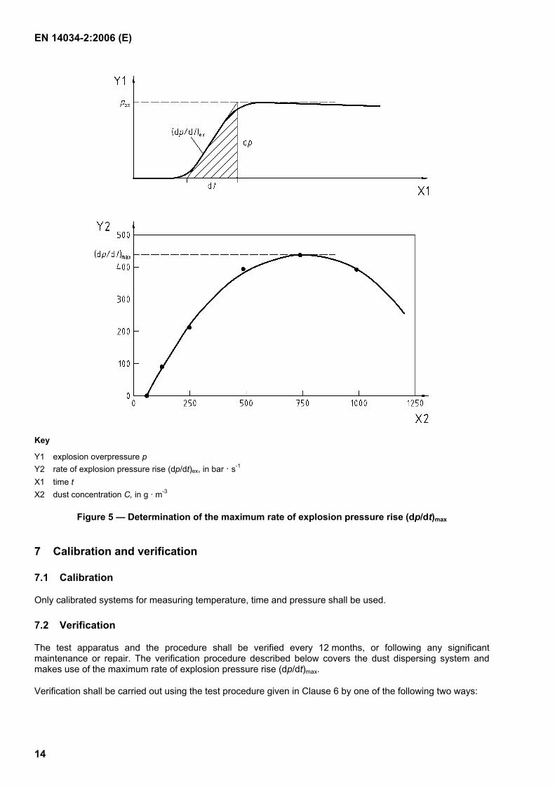
Determine the rate of explosion pressure rise (dp/dt)ex for each concentration and plot (dp/dt)ex against dust concentration until a maximum value of (dp/dt)ex is found.
Determinations shall be made for a minimum of two successive concentrations on both sides of the maximum value. This maximum value is the maximum rate of explosion pressure rise (dp/dt)max (see Figure 5).
If this procedure does not give a definite maximum value, the test series shall be repeated at least once in the range of the maximum value of the rate of explosion pressure rise. In such cases the arithmetic mean of the maximum values of each test series shall be taken as the maximum rate of explosion pressure rise (dp/dt)max.

EN 14034-2:2006 (E)
13
Key
Y1 overpressure in the dust container Y2 explosion overpressure in the 1 m3 vessel ta initiation of the fast acting valve t0 start of the dust dispersion tr reaction time of the fast acting valve tnd release time of the dust container into the 1 m³ vessel without dust trd time at the equalisation of the pressure between the dust container and the 1 m³ vessel ti activation of the ignition source tv ignition delay (0,6 ± 0,01) s
Figure 4 — Dust dispersion and pressure-time curve
EN 14034-2:2006 (E)
14
Key
Y1 explosion overpressure p Y2 rate of explosion pressure rise (dp/dt)ex, in bar · s-1 X1 time t X2 dust concentration C, in g · m-3
Figure 5 — Determination of the maximum rate of explosion pressure rise (dp/dt)max
7 Calibration and verification
7.1 Calibration
Only calibrated systems for measuring temperature, time and pressure shall be used.
7.2 Verification
The test apparatus and the procedure shall be verified every 12 months, or following any significant maintenance or repair. The verification procedure described below covers the dust dispersing system and makes use of the maximum rate of explosion pressure rise (dp/dt)max.
Verification shall be carried out using the test procedure given in Clause 6 by one of the following two ways:

EN 14034-2:2006 (E)
15
Internal verification with at least one reference dust for which the maximum rate of explosion pressure rise (dp/dt)max is known. The results of (dp/dt)max shall not deviate by more than the values given in Table 1 from the results previously obtained with the reference dust.
External verification by comparative measurement of the maximum rate of explosion pressure rise (dp/dt)max with at least one other laboratory with at least one dust. The results of (dp/dt)max shall not deviate by more than the values given in Table 1 from the results previously obtained by the other laboratory.
Table 1 — Maximum permissible deviations SEQ
(dp/dt)max
bar · s-1
Relative deviation
%
up to 50 ± 30
> 50 to 100 ± 20
> 100 to 200 ± 12
> 200 ± 10
For the purpose of internal calibration dusts shall be chosen on the basis of evidence that their (dp/dt)max does not change significantly over the period between calibrations.
8 Safety precautions / instructions
The instructions for use shall include at least the following warnings:
Precautions shall be taken to prevent accidental ignition by electrostatics, friction, impact or other means during the handling of the dust samples, blasting caps and chemical igniters.
Precautions shall be taken to ensure any openings in the explosion vessel, e.g. doors and ports, are properly closed before a test.
Precautions shall be taken to ensure that if the explosion vessel did fail during a test personnel are protected from the flying fragments produced, either by use of shielding or by location at a safe distance.
Before opening the explosion vessel any build up of internal pressure in the vessel shall be released.
Glowing material may be left adhering to the walls of the explosion vessel after a test. Precautions shall be taken to ensure that if this material bursts into flame when the vessel is opened personnel are not put at risk.
Toxic samples and reaction products shall be handled and disposed of in a way that will not cause harm to personnel or the environment.
9 Alternative test equipment / procedures
The maximum rate of explosion pressure rise (dp/dt)max of dust clouds can be determined using alternative test equipment and/or test procedures. When using an alternative it shall be shown that at least for the following dusts

EN 14034-2:2006 (E)
16
20 different dusts with (dp/dt)max in the range of > 0 bar · s-1 to 200 bar · s-1 (St 1),
10 different dusts with (dp/dt)max in the range of > 200 bar · s-1 to 300 bar · s-1 (St 2),
5 different dusts with (dp/dt)max in the range of > 300 bar · s-1 (St 3)
the method yields results within the deviations shown in Table 1. The dusts used shall include at least two metal powders, two natural organic powders, two synthetic organic powders and two coal dusts.
Details of an alternative method using the 20 l sphere, for which conformity has been proven, are given in Annex C.
10 Test report
The test report shall include at least the following information:
Name and address of the testing laboratory;
Unique identification of the test report;
Name, description and identification of the tested dust (characteristics);
Preparation of the dust sample for the tests;
Particle size distribution of the tested dust (incl. method);
Moisture content of the tested dust (incl. method);
If relevant a volatile content of the tested dust (incl. method);
Type of the test equipment and the test procedure used;
Any changes to the test equipment or test procedures specified in this standard, the reasons for the changes and any other information relevant to specific tests;
Initial temperature Ti in °C;
Initial pressure pi in bar;
A table or graph showing the measured values of (dp/dt)ex versus the dust concentration (corresponding to Figure 5);
Maximum rate of explosion pressure rise (dp/dt)max in bar · s-1;
The statement that the reported (dp/dt)max determined in the 1 m³ vessel is numerically identical with the parameters Kmax (EN 26184-1) and KSt but the units of the latter are bar · m · s-1 whereas the unit of the (dp/dt)max is bar · s-1;
The statement that the reported (dp/dt)max, 20 l (determined in the 20 l sphere as described in Annex C) leads to the Kmax or KSt by using the equation
Kmax = KSt = 0,271 · (dp/dt)max, 20 l [bar · m · s-1];
A statement to the effect that the test results relate only to the samples tested;
A statement that the result may deviate up to the value shown in Table 1.

EN 14034-2:2006 (E)
17
Annex A (normative)
Electro Pneumatic Valve
An alternative type of fast acting valve for which conformity has been proven, is the:
Electro Pneumatic Valve
A ball valve with an electro pneumatic drive (see Figure A.1) can be used instead of the fast acting valve described in 4.3. It shall be designed to withstand an overpressure of at least 20 bar and the opening time shall be < 100 ms. Valves meeting these requirements are commercially available.
Dimensions in millimeters
Key
1 dust container 2 electro pneumatic valve, DN 25 3 1” elbow, internal diameter: 27,7 mm 4 explosion vessel
Figure A.1 — Electro Pneumatic Valve (schematic)

EN 14034-2:2006 (E)
18
One indication of conformity is a dispersion characteristic lying between the ranges given in Figure A.2 (without dust).
Key
1 blasting cap activated valve 2 electro pneumatic valve
Figure A.2 — Discharge characteristic of dust dispersers (without dust)
For conformity the delay between the initiation of the dust dispersion (by activating the electro pneumatic valve) and activation of the ignition source shall be in the range of (0,6 ± 0,1) s. The value (x) for the ignition delay time (tv = (x ± 0,01) s) shall be determined by an external verification according to 7.2.

EN 14034-2:2006 (E)
19
Annex B (normative)
Dust dispenser with 5 mm holes
An alternative type of semicircular dust disperser (spray pipe) for which conformity has been proven, is the:
Dust disperser with 5 mm holes
The dust disperser, with an internal diameter of 21,7 mm (see 4.3) is fitted with 20 holes of a diameter of 5 mm (incl. one hole in each end cap) which are located according to Figure B.1.
NOTE 1 The dust disperser nozzles have been developed in Europe over many years. For historical reasons the size and number of holes in the pipes in current use vary somewhat. The two configurations specified in the standard and in this annex have been proven to yield practically identical results.
NOTE 2 For coarse, voluminous, fibrous or poorly flowing dust samples, it may not be possible to properly discharge the dust through the dust dispersers detailed in Figures 3 and B.1. It may, therefore, be necessary to use special dust dispersers, examples of which are given in Figures B.2 and B.3. In such cases, the dust disperser used should be described in the test report.

EN 14034-2:2006 (E)
20
Dimensions in millimeters
Key
1 end cap with 5 mm hole
Figure B.1 — Location of the 5 mm holes in the dust disperser

EN 14034-2:2006 (E)
21
Dimensions in millimeters
Figure B.2 — Rebound nozzle
Figure B.3 — Dispersion cup

EN 14034-2:2006 (E)
22
Annex C (normative)
20 l sphere
C.1 General
An alternative type of test equipment, for which conformity has been proven, is the:
20 l sphere
Limits of applicability
For coarse, voluminous, fibrous or poorly flowing dusts, it may not be possible to properly discharge the dust through the dispersing system described in this annex. In that case, the 1 m³ vessel shall be used (as far as possible).
C.2 Test apparatus
The explosion vessel is an explosion resistant hollow sphere in accordance with EN 14460 made of stainless steel, with a volume of 20 dm³. A water jacket serves to dissipate the heat from the explosions. For testing, the dust is dispersed into the sphere from a pressurised dust container via the fast acting valve and a rebound nozzle. The fast acting valve is pneumatically opened and closed by means of an auxiliary piston. The valves for the compressed air are activated electrically. The ignition source is located in the centre of the sphere. The pressure measuring system includes at least two pressure sensors, recording and control equipment (see Figure C.1).
Prior to dispersing the dust the sphere shall be partially evacuated to a pressure of 0,4 bar so after dust injection the pressure in the sphere (initial pressure pi) is equal to 1013 mbar.

EN 14034-2:2006 (E)
23
Key
1 water outlet 6 ignition source 2 pressure sensor 7 rebound nozzle 3 manometer 8 fast acting valve 4 dust container (0,6 dm3) 9 water inlet 5 air inlet 10 outlet (air, reaction products)
Figure C.1 — Test equipment 20 l sphere (schematic)
C.3 Test conditions
Dispersion overpressure pz = 20 bar;
Initial pressure pi = 1013 mbar (pre-evacuation of the explosion vessel down to 0,4 bar);
Initial temperature Ti = 20 °C (water cooling);
Ignition delay time tv = 60 ms;
Ignition source = two chemical igniters each having an energy of 5 kJ.
C.4 Test procedure
In general the test procedures described for the 1 m³ vessel (see Clause 6) shall be applied for the 20 l sphere.
An ignition of the dust has taken place, when the measured overpressure (influence of chemical igniters included) relative to the initial pressure pi is ≥ 0,5 bar [pex ≥ (pi + 0,5 bar)].
In the first test series, the rate of explosion pressure rise is determined over a range of concentrations. Starting with a concentration of 250 g · m-3 the concentration should be increased by steps of 250 g · m-3 or decreased by steps of about 50 % of the preceding concentration to the series shown below:

EN 14034-2:2006 (E)
24
... ; 60; 125; 250; 500; 750; 1000; 1250; 1500; ... g · m-3
Determinations shall be made for a minimum of two successive concentrations on both sides of the maximum value. This maximum value is considered the rate of explosion pressure rise (dp/dt)ex, [series 1].
Subsequently, two further test series, as described above, shall be carried out.
C.5 Calculation of (dp/dt)max, 20 l, Kmax and KSt
The maximum explosion pressure determined in closed, spherical or cubic vessels of sufficient size (V ≥ 20 dm3) with central ignition source, is practically independent of the volume of the vessel.
The maximum rate of explosion pressure rise determined in the 20 l sphere (dp/dt)max,20 l is defined as the arithmetic mean of the maximum values of the rate of explosion pressure rise (dp/dt)ex of each series as follows:
( ) ( ) [ ] ( ) [ ] ( ) [ ] [ ]13seriesex,2seriesex,1seriesex,lmax,20 sbar
3d/dd/dd/d
d/d −⋅++
=tptptp
tp (C.1)
The (dp/dt)max depends on the volume. It decreases with increasing volume. The Kmax or KSt value is dust and method specific but independent of volume. For the 20 l sphere the following equation applies:
( )
⋅⋅⋅== −1
maxStmax smbar/dd0,271 tpKK (C.2)

EN 14034-2:2006 (E)
25
Annex ZA (informative)
Relationship between this European Standard and the Essential Requirements of EU
Directive 94/9/EC
This European Standard has been prepared under a mandate given to CEN by the European Commission and the European Free Trade Association to provide a means of conforming to Essential Requirements of the New Approach Directive 94/9/EC of 23 March 1994 concerning equipment and protective systems intended for use in potentially explosive atmospheres.
Once this standard is cited in the Official Journal of the European Communities under that Directive and has been implemented as a national standard in at least one Member State, compliance with the normative clauses of this standard given in Table ZA.1 confers, within the limits of the scope of this standard, a presumption of conformity with the corresponding Essential Requirements of that Directive and associated EFTA regulations.
Table ZA.1 — Correspondence between this European Standard and Directive 94/9/EC
Clauses of this EN Essential Requirements (ER) of EU Directive 94/9/EC
Qualifying remarks / Notes
Clause 4 to Clause 10 and Annexes A, B and C
Annex II, Clause 1.0.1 Principles of integrated explosion safety
WARNING: Other requirements and other EU Directives may be applicable to the products falling within the scope of this standard.

EN 14034-2:2006 (E)
26
Bibliography
[1] ASTM E 1226 Standard, Test Method for Pressure and Rate of Pressure Rise for Combustible Dusts, Philadelphia, USA, 1988
[2] Beck, H. et al.: Combustion and explosion characteristics of dusts, BIA-Report 13/97, Hauptverband der gewerblichen Berufsgenossenschaften (HVBG), Sankt Augustin 1997
[3] Eckhoff, R. K.: Dust Explosion in the Process Industries, Butterworth-Heinemann, second edition Oxford 1997
[4] Bartknecht, W.: Explosionsschutz, Grundlagen und Anwendung, Springer-Verlag Berlin Heidelberg 1993
[5] Siwek, R.: Determination of technical safety indices and factors influencing hazard evaluation of dusts, Journal of Loss Prevention in the Process Industries, Elsevier Science Ltd., 1995
[6] Cesana, Ch.: Operating Instructions for the 20 l apparatus, Adolf Kühner AG, CH-4127 Birsfelden, Switzerland, 1999
[7] GESTIS-DUST-EX: Database with combustion and explosion characteristics of dusts, Hauptverband der gewerblichen Berufsgenossenschaften (HVBG), www.hvbg.de/bgia/gestis-dust-ex
[8] VDI 2263-1, Dust Fires and Dust Explosions – Hazards – Assessment; Protective Measures; Test Methods for the Determination of the Safety Characteristics of Dusts, Düsseldorf 1990
[9] EN 26184-1:1991, Explosion protection systems – Part 1: Determination of explosion indices of combustible dusts in air (ISO 6184-1:1985).
[10] EN ISO 1127; Stainless steel tubes – Dimensions, tolerances and conventional masses per unit length (ISO 1127:1992).
[11] ISO 4225, Air quality – General aspects – Vocabulary.

blank

BS EN 14034-2:2006
BSI
389 Chiswick High Road
London
W4 4AL
BSI — British Standards InstitutionBSI is the independent national body responsible for preparing British Standards. It presents the UK view on standards in Europe and at the international level. It is incorporated by Royal Charter.
Revisions
British Standards are updated by amendment or revision. Users of British Standards should make sure that they possess the latest amendments or editions.
It is the constant aim of BSI to improve the quality of our products and services. We would be grateful if anyone finding an inaccuracy or ambiguity while using this British Standard would inform the Secretary of the technical committee responsible, the identity of which can be found on the inside front cover. Tel: +44 (0)20 8996 9000. Fax: +44 (0)20 8996 7400.
BSI offers members an individual updating service called PLUS which ensures that subscribers automatically receive the latest editions of standards.
Buying standards
Orders for all BSI, international and foreign standards publications should be addressed to Customer Services. Tel: +44 (0)20 8996 9001. Fax: +44 (0)20 8996 7001. Email: [email protected]. Standards are also available from the BSI website at http://www.bsi-global.com.
In response to orders for international standards, it is BSI policy to supply the BSI implementation of those that have been published as British Standards, unless otherwise requested.
Information on standards
BSI provides a wide range of information on national, European and international standards through its Library and its Technical Help to Exporters Service. Various BSI electronic information services are also available which give details on all its products and services. Contact the Information Centre. Tel: +44 (0)20 8996 7111. Fax: +44 (0)20 8996 7048. Email: [email protected].
Subscribing members of BSI are kept up to date with standards developments and receive substantial discounts on the purchase price of standards. For details of these and other benefits contact Membership Administration. Tel: +44 (0)20 8996 7002. Fax: +44 (0)20 8996 7001. Email: [email protected].
Information regarding online access to British Standards via British Standards Online can be found at http://www.bsi-global.com/bsonline.
Further information about BSI is available on the BSI website at http://www.bsi-global.com.
Copyright
Copyright subsists in all BSI publications. BSI also holds the copyright, in the UK, of the publications of the international standardization bodies. Except as permitted under the Copyright, Designs and Patents Act 1988 no extract may be reproduced, stored in a retrieval system or transmitted in any form or by any means – electronic, photocopying, recording or otherwise – without prior written permission from BSI.
This does not preclude the free use, in the course of implementing the standard, of necessary details such as symbols, and size, type or grade designations. If these details are to be used for any other purpose than implementation then the prior written permission of BSI must be obtained.
Details and advice can be obtained from the Copyright & Licensing Manager. Tel: +44 (0)20 8996 7070. Fax: +44 (0)20 8996 7553. Email: [email protected].