detector (general, fm/csa nonincendive approval) … · detector (general, fm/csa nonincendive...
TRANSCRIPT
Specifications are subject to change without notice. - 1 - First issue: Feb. 1997 Rev.7: Jun. 2003
No. SS2-MGG200-0100 (Rev.7)
MagneW 3000 PLUS Smart Electromagnetic FlowmeterDetector (General, FM/CSA Nonincendive Approval)
Model MGG18, MGG19
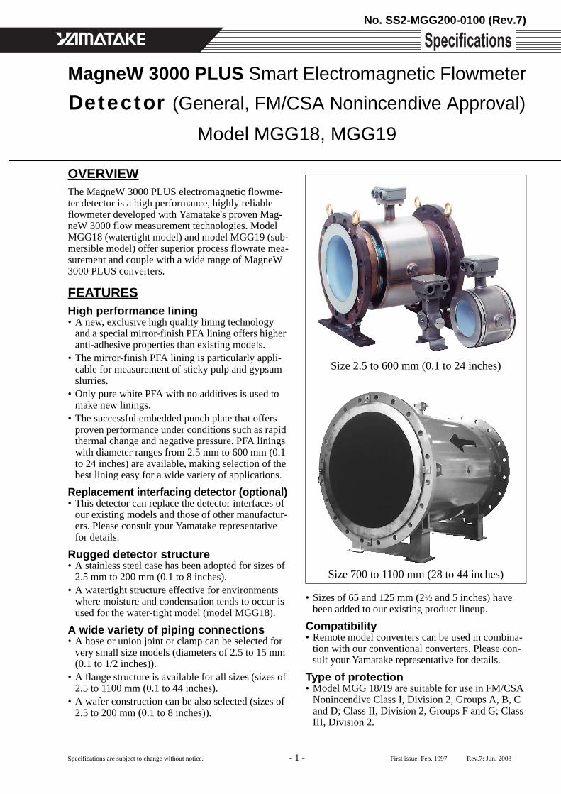
Size 2.5 to 600 mm (0.1 to 24 inches)
Size 700 to 1100 mm (28 to 44 inches)
OVERVIEWThe MagneW 3000 PLUS electromagnetic flowme-ter detector is a high performance, highly reliable flowmeter developed with Yamatake's proven Mag-neW 3000 flow measurement technologies. Model MGG18 (watertight model) and model MGG19 (sub-mersible model) offer superior process flowrate mea-surement and couple with a wide range of MagneW 3000 PLUS converters.
FEATURESHigh performance lining• A new, exclusive high quality lining technology
and a special mirror-finish PFA lining offers higher anti-adhesive properties than existing models.
• The mirror-finish PFA lining is particularly appli-cable for measurement of sticky pulp and gypsum slurries.
• Only pure white PFA with no additives is used to make new linings.
• The successful embedded punch plate that offers proven performance under conditions such as rapid thermal change and negative pressure. PFA linings with diameter ranges from 2.5 mm to 600 mm (0.1 to 24 inches) are available, making selection of the best lining easy for a wide variety of applications.
Replacement interfacing detector (optional)• This detector can replace the detector interfaces of
our existing models and those of other manufactur-ers. Please consult your Yamatake representative for details.
Rugged detector structure• A stainless steel case has been adopted for sizes of
2.5 mm to 200 mm (0.1 to 8 inches).• A watertight structure effective for environments
where moisture and condensation tends to occur is used for the water-tight model (model MGG18).
A wide variety of piping connections• A hose or union joint or clamp can be selected for
very small size models (diameters of 2.5 to 15 mm (0.1 to 1/2 inches)).
• A flange structure is available for all sizes (sizes of 2.5 to 1100 mm (0.1 to 44 inches).
• A wafer construction can be also selected (sizes of 2.5 to 200 mm (0.1 to 8 inches)).
• Sizes of 65 and 125 mm (2½ and 5 inches) have been added to our existing product lineup.
Compatibility• Remote model converters can be used in combina-
tion with our conventional converters. Please con-sult your Yamatake representative for details.
Type of protection • Model MGG 18/19 are suitable for use in FM/CSA
Nonincendive Class I, Division 2, Groups A, B, C and D; Class II, Division 2, Groups F and G; Class III, Division 2.

No. SS2-MGG200-0100 (Rev.7) Yamatake Corporation
- 2 -
APPLICATIONSPulp and paperPulp liquids, chemicals, corrosive liquids, industrial water, wastewater, etc.
Petroleum/petrochemical/chemicalsCorrosive liquids, dyestuffs, chemicals, industrial water, waste water, etc.
Public utilitiesWater supply systems, sewage systems, community drainage, human waste, sludge, sediment slurry, reg-ulation of total effluent, etc.
FoodPotable water, light, medium and high density fluids, industrial water, waste water, etc.
Steel/nonferrous metals/ceramicsAluminum slurry, cooling water, industrial water, corrosive liquids, wastewater, etc.
Machinery/equipment/electric machineryCorrosive liquids, cooking water, circulating water, industrial water, wastewater, etc.
ConstructionBuilding material slurry, sediment slurry, cement slurry, industrial water, etc.
Shipbuilding Sediment slurry etc.
Electric powerCorrosive liquids, cooling water, industrial water, wastewater, etc.
GasCirculating water for air conditioning, etc.
FUNCTIONAL SPECIFICATIONSType of protection
Model MGG18JIS C 0920 watertight modelNEMA TYPE4X, IEC IP67Model MGG19JIS C 0920 submersible modelNEMA TYPE6P, IEC IP68FM approval for bothNonincendive for Class I, Division 2, Groups A, B, C and DSuitable for Class II, Division 2, Groups F and GSuitable for Class III, Division 2, indoor and out-door (type 4X) hazardous locations.CSA approval for bothNonincendive for Class I, Division 2, Groups A, B, C, and DFor Class II, Division 2, Groups E, F and GFor Class III for used with non-flammable process fluids.
Line size2.5, 5, 10, 15, 25, 40, 50, 65, 80, 100, 125, 150, 200, 250, 300, 350, 400, 450, 500, 600, 700, 800, 900, 1000, 1100 mm(0.1, 0.2, 3/8, 1/2, 1, 1½, 2, 2½, 3, 4, 5, 6, 8, 10, 12, 14, 16, 18, 20, 24, 28, 32, 36, 40, 44 inches)
Flange ratingJIS 10K, JIS 16K, JIS 20K, JIS 30K, JPI 150, JPI 300, ANSI 150, ANSI 300, DIN PN10, DIN PN16, DIN PN25, DIN PN40(Size 2.5 to 50 mm (0.1 to 2 inches))JIS 10K, JIS 16K, JIS 20K, JIS 30K, JIS G3451 F12JPI 150, JPI 300,ANSI 150, ANSI 300, DIN PN10, DIN PN16, DIN PN25, DIN PN40(Size 80 to 200 mm (3 to 8 inches))JIS 10K, JIS 16K, JIS 20K, JIS G3451 F12JPI 150, JPI 300, ANSI 150, ANSI 300, DIN PN10, DIN PN16, DIN PN25(Size 250 to 600 mm (10 to 24 inches), PFA/ETFE lining)JIS 10K, JIS G3451 F12,JPI 150, ANSI 150, DIN PN10 (Size 250 to 600 mm (10 to 24 inches), chloroprene rubber lining)

Yamatake Corporation No. SS2-MGG200-0100 (Rev.7)
- 3 -
Measurement flow rangeRefer to the minimum/maximum set ranges shown in the table below
Flow conversion Velocity V(m/s) = K × Q K = Flow conversion factor =
Q = Flow rate (m3/h)Temperature range and pressure range of process fluid
SizeMinimum flow velocity range is
0 to 0.1 m/s (0 to 0.33 ft/s)Maximum flow velocity range is
0 to 10 m/s (0 to 32.8 ft/s) Conversion factor KMinimum range Maximum range
mm inch m3/h GPM m3/h GPM2.5 0.1 0 to 0.001768 0 to 0.007782 0 to 0.1767 0 to 0.7781 56.595 0.2 0 to 0.007069 0 to 0.03113 0 to 0.7068 0 to 3.112 14.15
10 3/8 0 to 0.02825 0 to 0.1246 0 to 2.827 0 to 12.45 3.53715 1/2 0 to 0.06362 0 to 0.2802 0 to 6.361 0 to 28.01 1.57225 1 0 to 0.1768 0 to 0.7782 0 to 17.67 0 to 77.81 0.565940 1½ 0 to 0.4524 0 to 1.993 0 to 45.23 0 to 199.2 0.221050 2 0 to 0.7069 0 to 3.113 0 to 70.68 0 to 311.2 0.141565 2½ 0 to 1.195 0 to 5.261 0 to 119.4 0 to 526.0 0.0837180 3 0 to 1.810 0 to 7.969 0 to 180.9 0 to 796.8 0.05526100 4 0 to 2.828 0 to 12.46 0 to 282.7 0 to 1245 0.03537125 5 0 to 4.418 0 to 19.46 0 to 441.7 0 to 1945 0.02264150 6 0 to 6.362 0 to 28.02 0 to636.1 0 to 2801 0.01572200 8 0 to 11.31 0 to 49.81 0 to 1130 0 to 4980 0.008842250 10 0 to 17.68 0 to 77.82 0 to 1767 0 to 7781 0.005659300 12 0 to 25.45 0 to 112.1 0 to 2544 0 to 11205 0.003930350 14 0 to 34.64 0 to 152.6 0 to 3463 0 to 15251 0.002887400 16 0 to 45.24 0 to 199.3 0 to 4523 0 to 19920 0.002210450 18 0 to 57.26 0 to 252.2 0 to 5725 0 to 25211 0.001747500 20 0 to 70.69 0 to 311.3 0 to 7068 0 to 31125 0.001415600 24 0 to 101.8 0 to 448.3 0 to 10178 0 to 44820 0.0009824700 28 0 to 138.6 0 to 610.1 0 to 13854 0 to 61005 0.0007218800 32 0 to 181.0 0 to 796.9 0 to 18095 0 to 79680 0.0005526900 36 0 to 229.1 0 to 1009 0 to 22902 0 to 100846 0.0004366
1000 40 0 to 282.8 0 to 1246 0 to 28274 0 to 124501 0.00035371100 44 0 to 342.2 0 to 1507 0 to 34211 0 to 150646 0.0002923
13600------------ 4
πD2----------×
Size 15 to 200 mm (1/2 to 8 inches)
Size 2.5 to 10 mm (0.1 to 3/8 inch)2.94 MPa(426 psi)
1.96 MPa(284 psi)
-0.098 MPa(-14.2 psi)
2.94 MPa(426 psi)
-0.098 MPa(-14.2 psi)
-40(-40)
80(176)
100 C(212 F)
0.098 MPa(142 psi)
-40(-40)
50(122)
80(176)
120(248)
160 C(320 F)
Size 250 to 1100 mm (10 to 44 inches)1.96 MPa(284 psi)
-0.098 MPa(-14.2 psi)
0.098 MPa(142 psi)
-40(-40)
-10(14)
70(158)
100(212)
120 C(248 F)
Chloroprene rubber andPFA / ETFE liningPolyurethane rubber and PFA / ETFE lining
PFA/ETFE lining
PFA lining (Remote model only)
PFA lining
Special products

No. SS2-MGG200-0100 (Rev.7) Yamatake Corporation
- 4 -
Ambient temperature limits-25 to +60°C (-13 to +140°F) (integral model)-30 to +80°C (-22 to +176°F) (remote model, PFA lining)30 to +60°C (-22 to +140°F) (remote model, polyure-thane rubber lining/chloroprene rubber lining)
Ambient humidity limits5 to 100% RH
Measurable electrical conductivityCombined with model MGG14C converter 3 µS/cm or more
Optional specificationsTest reportCalibration certificate, withstand voltage test, insu-lation resistant, hydrostatic pressure test, physical inspection are included.Traceability certificateThe following three documents are included.• Traceability System Chart• Traceability Certificate• Test ReportMaterial certificate Material certificate for electrode/grounding ringGasket for plastic pipingWhen the detector is being mounted on plastic pipe, attach this gasket between the lining and the grounding ring, and between the grounding ring and the plastic pipe flange.Attaching the tag number to the terminal boxStamp the tag with the specified number and attach to the terminal box. The maximum number of char-acters of the tag number is 8.Attaching the tag number to the neck sectionStamp the tag with the specified number and attach to the neck section of the detector with stainless wire. The maximum number of characters of the tag number is 16.
PERFORMANCE SPECIFICATIONSAccuracy (in combination with the model MGG14C converter)<Size 2.5 to 15 mm (0.1 to 1/2 inch)>Vs = Velocity of setting range
<Size 25 to 600 mm (1 to 24 inches)>Vs = Velocity of setting range
<Size 700 to 1100 mm (28 to 44 inches)>Vs = Velocity of setting range
PHYSICAL SPECIFICATIONSMain body material
Measuring pipe materials SUS304 stainless steel FlangeSUS304 stainless steel (size 2.5 to 65 mm (0.1 to 2½ inches))Carbon steel + corrosion-preventive coating (size 80 to 600 mm (3 to 24 inches))CaseSCS13 stainless steel (size 2.5 to 15 mm (0.1 to 1/2 inch))SUS304 stainless steel (size 25 to 200 mm (1 to 8 inches))SS400 carbon steel (size 250 to 1100 mm (10 to 44 inches))Terminal boxAluminum alloy (remote model)
Vs (m/s)Velocity during measurement >
Vs × 40%
Velocity during measurement < Vs
× 40%1.0 < Vs < 10 ±0.5% of rate ±0.2% of Vs
0.1 < Vs < 1.0 ±(0.1/Vs+0.4)% of rate
±0.4(0.1/Vs+0.4)% of Vs
Vs (m/s)Velocity during measurement >
Vs × 20%
Velocity during measurement < Vs
× 20%1.0 < Vs < 10 ±0.5% of rate ±0.1% of Vs
0.1 < Vs < 1.0 ±(0.1/Vs+0.4)% of rate
±0.2 (0.1/Vs+0.4)% of Vs
Vs (m/s)Velocity during measurement >
Vs × 50%
Velocity during measurement < Vs
× 50%1.0 < Vs < 10 ±1.0% of rate ±0.5% of Vs
0.1 < Vs < 1.0 ±(0.2/Vs+0.8)% of rate (0.1/Vs+0.4)% of Vs

Yamatake Corporation No. SS2-MGG200-0100 (Rev.7)
- 5 -
FinishModel MGG18
StandardTerminal box
Baked acryl paintCase (size 250 to 1100 mm (10 to 44 inches))
Polyurethane paintCorrosion-resistantTerminal box
Baked acryl paintCase (size 250 to 1100 mm (10 to 44 inches))
Polyurethane paintCorrosion-proofTerminal box
Baked epoxy paintCase (size 250 to 1100 mm (10 to 44 inches))
Epoxy paintColorLight beige (Munsell 4Y7.2/1.3)
Model MGG19Terminal box and case
Corrosion-proof tar epoxy paint, black
Process wetted materialLiningPFA (size 2.5 to 600 mm (0.1 to 24 inches))ETFE (size 80 to 600 mm (3 to 24 inches))Polyurethane rubber (size 25 to 200 mm (1 to 8 inches))Chloroprene rubber (size 250 to 1100 mm (10 to 44 inches))Electrode SUS316L, Hastelloy C, titanium, zirconium, tanta-lum, tungsten-carbide, platinum/iridiumGrounding ring SUS316, Hastelloy C, titanium, zirconium, tanta-lum, platinum Union jointSUS316 (size 2.5 to 15mm (0.1 to 1/2 inch))HoseSUS316 (size 2.5 to 15mm (0.1 to 1/2 inch))IDF ClampSUS316 (size 2.5 to 15mm (0.1 to 1/2 inch))Tri ClampSUS316 (size 2.5 to 15mm (0.1 to 1/2 inch))Gasket PTFE (if the grounding ring is not made of SUS316)O-ringViton rubber (with union joints)
INSTALLATIONElectrical connection
Integral modelConnected to converterRemote model
General modelG1/2 (PF1/2) internal thread, CM20 internal thread, Pg 13.5 internal thread.FM/CSA Nonincendive model1/2NPT internal thread for model MGG18Watertight gland for model MGG19
Pipe connectionWafer (size 2.5 to 200 mm (0.1 to 8 inches))Flange (size 2.5 to 1100 mm (0.1 to 44 inches))Union (size 2.5 to 15 mm (0.1 to 1/2 inch))Hose (size 2.5 to 15 mm (0.1 to 1/2 inch))IDF Clamp (size 2.5 to 15 mm (0.1 to 1/2 inch))Tri Clamp (size 2.5 to 15 mm (0.1 to 1/2 inch))
Nuts and bolts (for wafer models)S20C carbon steel, SUS304 stainless steel
GroundingResistance less than 100 Ω
Length of straight pipeUpstream sideA minimum five straight pipe diametersA minimum 10 straight pipe diameters is required if a diffuser/valve/pump is installed upstream side.Downstream sideTwo straight pipe diameters is recommended.
Cable (between remote detector and converter)Maximum length 300 m (984 ft)(depends on fluid conductivity)Outer diameter 10 to 12 mm (0.4 to 0.47 inch)
Signal cableDedicated cable: MGA12W(O.D. 11.4 mm, 0.75 mm2) or equivalent (CVVS, CEEV etc.)Excitation cableDedicated cable: MGA12W(O.D. 10.5 mm, 2 mm2) or equivalent (CVV and others)
No. SS2-MGG200-0100 (Rev.7) Yamatake Corporation
- 6 -
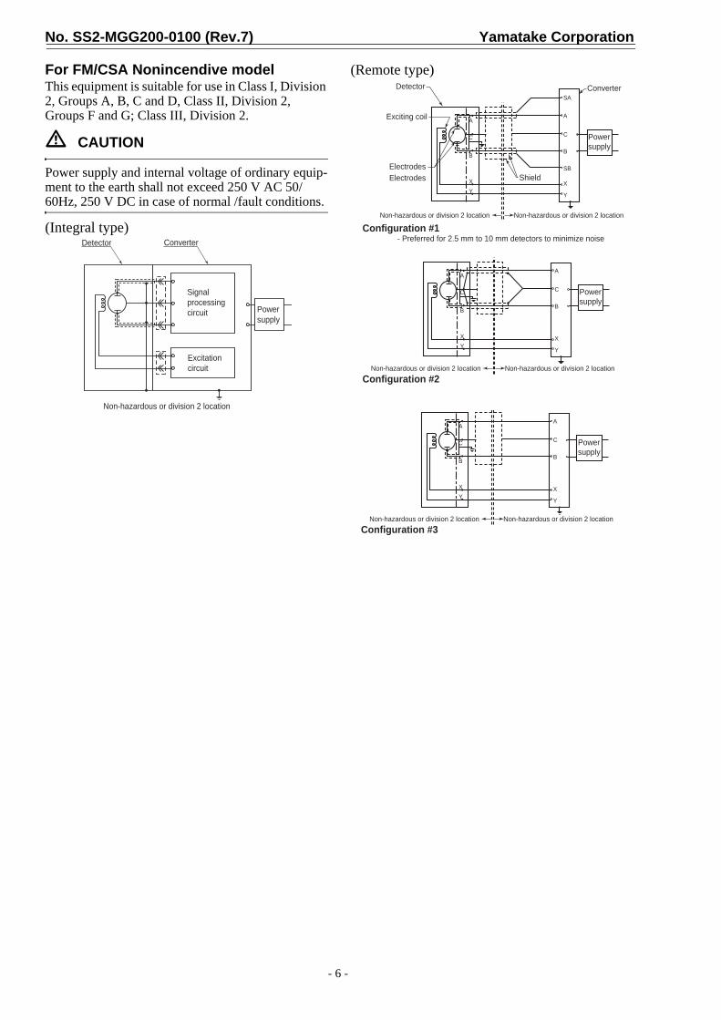
For FM/CSA Nonincendive modelThis equipment is suitable for use in Class I, Division 2, Groups A, B, C and D, Class II, Division 2, Groups F and G; Class III, Division 2.
CAUTION
Power supply and internal voltage of ordinary equip-ment to the earth shall not exceed 250 V AC 50/60Hz, 250 V DC in case of normal /fault conditions.
(Integral type)
(Remote type)
Detector Converter
Signalprocessingcircuit
Excitationcircuit
Powersupply
Non-hazardous or division 2 location
ElectrodesElectrodes
Exciting coil
Detector
A
C
B
XY
SA
A
C
B
SB
X
Y
Converter
Shield
Powersupply
Non-hazardous or division 2 location Non-hazardous or division 2 location
Non-hazardous or division 2 location Non-hazardous or division 2 location
A
C
B
XY
A
C
B
X
Y
Powersupply
Configuration #1 - Preferred for 2.5 mm to 10 mm detectors to minimize noise
Configuration #2
Non-hazardous or division 2 location Non-hazardous or division 2 location
A
C
B
XY
A
C
B
X
Y
Powersupply
Configuration #3

Yamatake Corporation No. SS2-MGG200-0100 (Rev.7)
- 7 -
MODEL SELECTIONContents of model number tableDetector (General model)
Detector (Submersible model)
Note) All MGG19 models satisfy FM/CSA Nonincendive approval.
Structure / Basic model no. Lining Pipe connection Size Ref. page
Watertight model MGG18U PFA Union / Hose / Clamp 2.5 to 15 mm (0.1 to 1/2 inch) page 8Watertight model MGG18D PFA Wafer 2.5 to 10 mm (0.1 to 3/8 inch) page 9Watertight model MGG18D PFA / ETFE Wafer 15 to 200 mm (1/2 to 8 inches) page 10Watertight model MGG18F PFA / ETFE Flange 15 to 200 mm (1/2 to 8 inches) page 11Watertight model MGG18F PFA / ETFE Flange 250 to 600 mm (10 to 24 inches) page 12Watertight model MGG18D Polyurethane rubber Wafer 25 to 200 mm (1 to 8 inches) page 13Watertight model MGG18F Polyurethane rubber Flange 25 to 200 mm (1 to 8 inches) page 14Watertight model MGG18F Chloroprene rubber Flange 250 to 600 mm (10 to 24 inches) page 15Watertight model MGG18F Chloroprene rubber Flange 700 to 1100 mm (28 to 44 inches) page 16
Structure / Basic model no. Lining Pipe connection Size Ref. page
Submersible model MGG19D PFA / ETFE Wafer 15 to 200 mm (1/2 to 8 inches) page 17Submersible model MGG19F PFA / ETFE Flange 15 to 200 mm (1/2 to 8 inches) page 18Submersible model MGG19F PFA / ETFE Flange 250 to 600 mm (10 to 24 inches) page 19Submersible model MGG19D Polyurethane rubber Wafer 25 to 200 mm (1 to 8 inches) page 20Submersible model MGG19F Polyurethane rubber Flange 25 to 200 mm (1 to 8 inches) page 21
PFA / ETFE liningRubber lining
No. SS2-MGG200-0100 (Rev.7) Yamatake Corporation
- 8 -
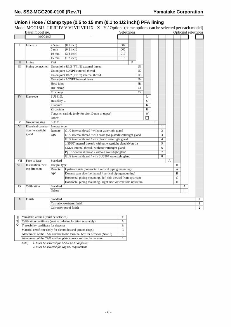
Union / Hose / Clamp type (2.5 to 15 mm (0.1 to 1/2 inch)) PFA liningModel MGG18U - I II III IV V VI VII VIII IX - X - Y / Options (some options can be selected per each model)
Basic model no. Selections Optional selections
Note) 1. Must be selected for CSA/FM NI approval2. Must be selected for Tag no. requirement
MGG18U - -
I Line size 2.5 mm (0.1 inch) 0025 mm (0.2 inch) 00510 mm (3/8 inch) 01015 mm (1/2 inch) 015
II Lining PFA PIII Piping connection Union joint R1/2 (PT1/2) external thread U1
Union joint 1/2NPT external thread U2Union joint R1/2 (PT1/2) internal thread U3Union joint 1/2NPT internal thread U4Hose joint H1IDF clamp C1Tri clamp C2
IV Electrode SUS316L LHastelloy C CTitanium KZirconium HTungsten carbide (only for size 10 mm or upper) WOthers
V Grounding ring SUS316 SVI Electrical connec-
tion / watertight gland
Integral type 1Remote type
G1/2 internal thread / without watertight gland 2G1/2 internal thread / with brass (Ni-plated) watertight gland 3G1/2 internal thread / with plastic watertight gland 41/2NPT internal thread / without watertight gland (Note 1) 5CM20 internal thread / without watertight gland 6Pg 13.5 internal thread / without watertight gland 7G1/2 internal thread / with SUS304 watertight gland 8
VII Face-to-face Standard AVIII Installation / wir-
ing directionIntegral type HRemote type
Upstream side (horizontal / vertical piping mounting) ADownstream side (horizontal / vertical piping mounting) BHorizontal piping mounting / left side viewed from upstream CHorizontal piping mounting / right side viewed from upstream D
IX Calibration Standard AOthers
X Finish Standard XCorrosion-resistant finish 1Corrosion-proof finish 2
Opt
ions Yamatake version (must be selected) Y
Calibration certificate (sent to ordering location separately) ATraceability certificate for detector BMaterial certificate (only for electrodes and ground rings) CAttachment of the TAG number to the terminal box for detector (Note 2) KAttachment of the TAG number plate to neck section for detector L

Yamatake Corporation No. SS2-MGG200-0100 (Rev.7)
- 9 -
Wafer type (2.5 to 10 mm (0.1 to 3/8 inch)) PFA liningModel MGG18D - I II III IV V VI VII VIII IX - X XI - Y / Options (some options can be selected per each model)
Basic model no. Selections Optional selectionsMGG18D - -
I Line size 2.5 mm (0.1 inch) 0025 mm (0.2 inch) 00510 mm (3/8 inch) 010
II Lining PFA PIII Piping connection Wafer JIS 10K 11
Wafer JIS 20K 12Wafer JIS 30K 13Wafer JIS 10/20K for 10 mm flange 14Wafer JIS 30K for 10 mm flange 15Wafer ANSI 150 21Wafer ANSI 300 22Wafer DIN PN10 41Wafer DIN PN16 42Wafer DIN PN25 43Wafer DIN PN40 44Wafer DIN PN10/16/25/40 for 10 mm flange 45Wafer JPI 150 61Wafer JPI 300 62
IV Electrode SUS316L LHastelloy C CTitanium KZirconium HTantalum TTungsten carbide (only for size 10 mm) WPlatinum iridium POthers
V Grounding ring SUS316 SHastelloy C CTitanium KZirconium HTantalum TPlatinum iridium POthers
VI Electrical connec-tion / watertight gland
Integral type 1Remote type
G1/2 internal thread / without watertight gland 2G1/2 internal thread / with brass (Ni-plated) watertight gland 3G1/2 internal thread / with plastic watertight gland 41/2NPT internal thread / without watertight gland (Note 1) 5CM20 internal thread / without watertight gland 6Pg 13.5 internal thread / without watertight gland 7G1/2 internal thread / with SUS304 watertight gland 8
VII Face-to-face dimensions
Standard AOthers
VIII Installation / wir-ing direction
Integral type HRemote type
Upstream side (horizontal / vertical piping mounting) ADownstream side (horizontal / vertical piping mounting) BHorizontal piping mounting / left side viewed from upstream CHorizontal piping mounting / right side viewed from upstream D
IX Calibration Standard AOthers
X Finish Standard XCorrosion-resistant finish 1Corrosion-proof finish 2
XI Bolt / nut None XCarbon steel 1SUS304 2
Opt
ions Yamatake version (must be selected) Y
Note) 1. Must be selected for CSA/FM NI approval2. Must be selected for Tag no. requirement
Calibration certificate (sent to ordering location separately) ATraceability certificate for detector BMaterial certificate (only for electrodes and ground rings) CWith gasket for plastic piping JAttachment of the TAG number to the terminal box for detector (Note 2) KAttachment of the TAG number plate to neck section for detector L

No. SS2-MGG200-0100 (Rev.7) Yamatake Corporation
- 10 -
Wafer type (15 to 200 mm (1/2 to 8 inches)) PFA / ETFE liningModel MGG18D - I II III IV V VI VII VIII IX - X XI - Y / Options (some options can be selected per each model)
Basic model no. Selections Optional selectionsMGG18D - -
I Line size 15 mm (1/2 inch) 01525 mm (1 inch) 02540 mm (1½ inches) 04050 mm (2 inches) 05065 mm (2½ inches) 06580 mm (3 inches) 080100 mm (4 inches) 100125 mm (5 inches) 125150 mm (6 inches) 150200 mm (8 inches) 200
II Lining ETFE (Size 80 to 200 mm (3 to 8 inches)) EPFA P
III Piping connection Wafer JIS 10K 11Wafer JIS 20K 12Wafer JIS 30K 13Wafer ANSI 150 21Wafer ANSI 300 22Wafer JIS G3451 F12 (size 80 mm or larger) 31Wafer DIN PN10 41Wafer DIN PN16 42Wafer DIN PN25 43Wafer DIN PN40 44Wafer JPI 150 61Wafer JPI 300 62
IV Electrode SUS316L LHastelloy C CTitanium KZirconium HTantalum TTungsten carbide WPlatinum iridium POthers
V Grounding ring SUS316 SHastelloy C CTitanium KZirconium HTantalum TPlatinum iridium POthers
VI Electrical connec-tion / watertight gland
Integral type 1Remote type
G1/2 internal thread / without watertight gland 2G1/2 internal thread / with brass (Ni-plated) watertight gland 3G1/2 internal thread / with plastic watertight gland 41/2NPT internal thread / without watertight gland (Note 1) 5CM20 internal thread / without watertight gland 6Pg 13.5 internal thread / without watertight gland 7G1/2 internal thread / with SUS304 watertight gland 8
VII Face-to-face dimen-sions
Standard AOthers
VIII Installation / wiring direction
Integral type HRemote type
Upstream side (horizontal / vertical piping mounting) ADownstream side (horizontal / vertical piping mounting) BHorizontal piping mounting / left side viewed from upstream CHorizontal piping mounting / right side viewed from upstream D
IX Calibration Standard AOthers
X Finish Standard XCorrosion-resistant finish 1Corrosion-proof finish 2
XI Bolt / nut None XCarbon steel 1SUS304 2
Opt
ions Yamatake version (must be selected) Y
Note) 1. Must be selected for CSA/FM NI approval2. Must be selected for Tag no. requirement
Calibration certificate (sent to ordering location separately) ATraceability certificate for detector BMaterial certificate (only for electrodes and ground rings) CWith gasket for plastic piping JAttachment of the TAG number to the terminal box for detector (Note 2) KAttachment of the TAG number plate to neck section for detector L
Yamatake Corporation No. SS2-MGG200-0100 (Rev.7)
- 11 -
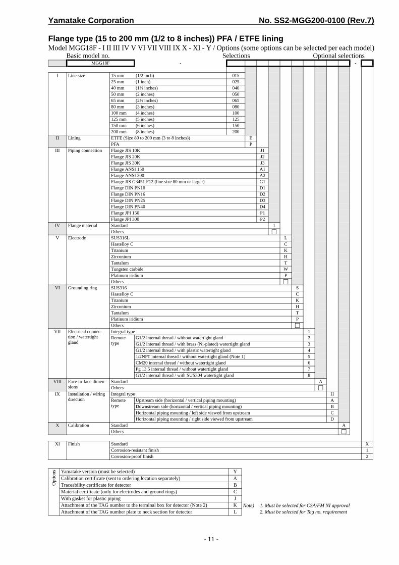
Flange type (15 to 200 mm (1/2 to 8 inches)) PFA / ETFE liningModel MGG18F - I II III IV V VI VII VIII IX X - XI - Y / Options (some options can be selected per each model)
Basic model no. Selections Optional selectionsMGG18F - -
I Line size 15 mm (1/2 inch) 01525 mm (1 inch) 02540 mm (1½ inches) 04050 mm (2 inches) 05065 mm (2½ inches) 06580 mm (3 inches) 080100 mm (4 inches) 100125 mm (5 inches) 125150 mm (6 inches) 150200 mm (8 inches) 200
II Lining ETFE (Size 80 to 200 mm (3 to 8 inches)) EPFA P
III Piping connection Flange JIS 10K J1Flange JIS 20K J2Flange JIS 30K J3Flange ANSI 150 A1Flange ANSI 300 A2Flange JIS G3451 F12 (line size 80 mm or larger) G1Flange DIN PN10 D1Flange DIN PN16 D2Flange DIN PN25 D3Flange DIN PN40 D4Flange JPI 150 P1Flange JPI 300 P2
IV Flange material Standard 1Others
V Electrode SUS316L LHastelloy C CTitanium KZirconium HTantalum TTungsten carbide WPlatinum iridium POthers
VI Grounding ring SUS316 SHastelloy C CTitanium KZirconium HTantalum TPlatinum iridium POthers
VII Electrical connec-tion / watertight gland
Integral type 1Remote type
G1/2 internal thread / without watertight gland 2G1/2 internal thread / with brass (Ni-plated) watertight gland 3G1/2 internal thread / with plastic watertight gland 41/2NPT internal thread / without watertight gland (Note 1) 5CM20 internal thread / without watertight gland 6Pg 13.5 internal thread / without watertight gland 7G1/2 internal thread / with SUS304 watertight gland 8
VIII Face-to-face dimen-sions
Standard AOthers
IX Installation / wiring direction
Integral type HRemote type
Upstream side (horizontal / vertical piping mounting) ADownstream side (horizontal / vertical piping mounting) BHorizontal piping mounting / left side viewed from upstream CHorizontal piping mounting / right side viewed from upstream D
X Calibration Standard AOthers
XI Finish Standard XCorrosion-resistant finish 1Corrosion-proof finish 2
Opt
ions Yamatake version (must be selected) Y
Note) 1. Must be selected for CSA/FM NI approval2. Must be selected for Tag no. requirement
Calibration certificate (sent to ordering location separately) ATraceability certificate for detector BMaterial certificate (only for electrodes and ground rings) CWith gasket for plastic piping JAttachment of the TAG number to the terminal box for detector (Note 2) KAttachment of the TAG number plate to neck section for detector L

No. SS2-MGG200-0100 (Rev.7) Yamatake Corporation
- 12 -
Flange type (250 to 600 mm (10 to 24 inches)) PFA / ETFE liningModel MGG18F - I II III IV V VI VII VIII IX X - XI - Y / Options (some options can be selected per each model)
Basic model no. Selections Optional selectionsMGG18F - -
I Line size 250 mm (10 inches) 250300 mm (12 inches) 300350 mm (14 inches) 350400 mm (16 inches) 400450 mm (18 inches) 450500 mm (20 inches) 500600 mm (24 inches) 600
II Lining ETFE EPFA P
III Piping connection Flange JIS 10K J1Flange JIS 20K J2Flange ANSI 150 A1Flange ANSI 300 (Size 16 inches or smaller) A2Flange JIS G3451 F12 G1Flange DIN PN10 D1Flange DIN PN16 D2Flange DIN PN25 D3Flange JPI 150 P1Flange JPI 300 (Size 400 mm or smaller) P2
IV Flange material Standard 1Others
V Electrode SUS316L LHastelloy C CTitanium KZirconium HTantalum TTungsten carbide WPlatinum iridium POthers
VI Grounding ring SUS316 SHastelloy C CTitanium KOthers
VII Electrical connec-tion / watertight gland
Integral type 1Remote type
G1/2 internal thread / without watertight gland 2G1/2 internal thread / with brass (Ni-plated) watertight gland 3G1/2 internal thread / with plastic watertight gland 41/2NPT internal thread / without watertight gland (Note 1) 5CM20 internal thread / without watertight gland 6Pg 13.5 internal thread / without watertight gland 7G1/2 internal thread / with SUS304 watertight gland 8
VIII Face-to-face dimensions
Standard AOthers
IX Installation / wir-ing direction
Integral type HRemote type
Upstream side (horizontal / vertical piping mounting) ADownstream side (horizontal / vertical piping mounting) BHorizontal piping mounting / left side viewed from upstream CHorizontal piping mounting / right side viewed from upstream D
X Calibration Standard AOthers
XI Finish Standard XCorrosion-resistant finish 1Corrosion-proof finish 2
Opt
ions Yamatake version (must be selected) Y
Note) 1. Must be selected for CSA/FM NI approval.2. Must be selected for Tag no. requirement.
Calibration certificate (sent to ordering location separately) ATraceability certificate for detector BMaterial certificate (only for electrodes and ground rings) CWith gasket for plastic piping JAttachment of the TAG number to the terminal box for detector (Note 2) KAttachment of the TAG number plate to neck section for detector L

Yamatake Corporation No. SS2-MGG200-0100 (Rev.7)
- 13 -
Wafer type (25 to 200 mm (1 to 8 inches)) Polyurethane rubber liningModel MGG18D - I II III IV V VI VII VIII IX - X XI - Y / Options (some options can be selected per each model)
Basic model no. Selections Optional selectionsMGG18D - -
I Line size 25 mm (1 inch) 02540 mm (1½ inches) 04050 mm (2 inches) 05065 mm (2½ inches) 06580 mm (3 inches) 080100 mm (4 inches) 100125 mm (5 inches) 125150 mm (6 inches) 150200 mm (8 inches) 200
II Lining Polyurethane rubber QIII Piping connection Wafer JIS 10K 11
Wafer JIS 20K 12Wafer JIS 30K 13Wafer ANSI 150 21Wafer ANSI 300 22Wafer JIS G3451 F12 (line size 80 mm or larger) 31Wafer DIN PN10 41Wafer DIN PN16 42Wafer DIN PN25 43Wafer DIN PN40 44Wafer JPI 150 61Wafer JPI 300 62
IV Electrode SUS316L LTitanium KTungsten carbide (only for size 10 mm) WOthers
V Grounding ring SUS316 STitanium KOthers
VI Electrical connec-tion / watertight gland
Integral type 1Remote type
G1/2 internal thread / without watertight gland 2G1/2 internal thread / with brass (Ni-plated) watertight gland 3G1/2 internal thread / with plastic watertight gland 41/2NPT internal thread / without watertight gland (Note 1) 5CM20 internal thread / without watertight gland 6Pg 13.5 internal thread / without watertight gland 7G1/2 internal thread / with SUS304 watertight gland 8
VII Face-to-face dimensions Standard A
VIII Installation / wir-ing direction
Integral type HRemote type
Upstream side (horizontal / vertical piping mounting) ADownstream side (horizontal / vertical piping mounting) BHorizontal piping mounting / left side viewed from upstream CHorizontal piping mounting / right side viewed from upstream D
IX Calibration Standard AOthers
X Finish Standard XCorrosion-resistant finish 1Corrosion-proof finish 2
XI Bolt / nut None XCarbon steel 1SUS304 2
Opt
ions Yamatake version (must be selected) Y
Note) 1. Must be selected for CSA/FM NI approval2. Must be selected for Tag no. requirement
Calibration certificate (sent to ordering location separately) ATraceability certificate for detector BMaterial certificate (only for electrodes and ground rings) CWith gasket for plastic piping JAttachment of the TAG number to the terminal box for detector (Note 2) KAttachment of the TAG number plate to neck section for detector L

No. SS2-MGG200-0100 (Rev.7) Yamatake Corporation
- 14 -
Flange type (25 to 200 mm (1 to 8 inches)) Polyurethane rubber liningModel MGG18F - I II III IV V VI VII VIII IX X - XI - Y / Options (some options can be selected per each model)
Basic model no. Selections Optional selectionsMGG18F - -
I Line size 25 mm (1 inch) 02540 mm (1½ inches) 04050 mm (2 inches) 05065 mm (2½ inches) 06580 mm (3 inches) 080100 mm (4 inches) 100125 mm (5 inches) 125150 mm (6 inches) 150200 mm (8 inches) 200
II Lining Polyurethane rubber QIII Piping connection Flange JIS 10K J1
Flange JIS 20K J2Flange JIS 30K J3Flange ANSI 150 A1Flange ANSI 300 A2Flange JIS G3451 F12 (line size 80 mm or larger) G1Flange DIN PN10 D1Flange DIN PN16 D2Flange DIN PN25 D3Flange DIN PN40 D4Flange JPI 150 P1Flange JPI 300 P2
IV Flange material Standard 1Others
V Electrode SUS316L LTitanium KTungsten carbide (only for size 10 mm) WOthers
VI Grounding ring SUS316 STitanium KOthers
VII Electrical connec-tion / watertight gland
Integral type 1Remote type
G1/2 internal thread / without watertight gland 2G1/2 internal thread / with brass (Ni-plated) watertight gland 3G1/2 internal thread / with plastic watertight gland 41/2NPT internal thread / without watertight gland (Note 1) 5CM20 internal thread / without watertight gland 6Pg 13.5 internal thread / without watertight gland 7G1/2 internal thread / with SUS304 watertight gland 8
VIII Face-to-face dimensions Standard A
IX Installation / wir-ing direction
Integral type HRemote type
Upstream side (horizontal / vertical piping mounting) ADownstream side (horizontal / vertical piping mounting) BHorizontal piping mounting / left side viewed from upstream CHorizontal piping mounting / right side viewed from upstream D
X Calibration Standard AOthers
XI Finish Standard XCorrosion-resistant finish 1Corrosion-proof finish 2
Opt
ions Yamatake version (must be selected) Y
Note) 1. Must be selected for CSA/FM NI approval2. Must be selected for Tag no. requirement
Calibration certificate (sent to ordering location separately) ATraceability certificate for detector BMaterial certificate (only for electrodes and ground rings) CWith gasket for plastic piping JAttachment of the TAG number to the terminal box for detector (Note 2) KAttachment of the TAG number plate to neck section for detector L
Yamatake Corporation No. SS2-MGG200-0100 (Rev.7)
- 15 -
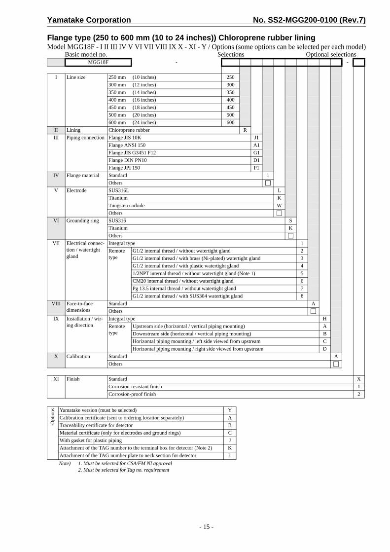
Flange type (250 to 600 mm (10 to 24 inches)) Chloroprene rubber liningModel MGG18F - I II III IV V VI VII VIII IX X - XI - Y / Options (some options can be selected per each model)
Basic model no. Selections Optional selections
Note) 1. Must be selected for CSA/FM NI approval2. Must be selected for Tag no. requirement
MGG18F - -
I Line size 250 mm (10 inches) 250300 mm (12 inches) 300350 mm (14 inches) 350400 mm (16 inches) 400450 mm (18 inches) 450500 mm (20 inches) 500600 mm (24 inches) 600
II Lining Chloroprene rubber RIII Piping connection Flange JIS 10K J1
Flange ANSI 150 A1Flange JIS G3451 F12 G1Flange DIN PN10 D1Flange JPI 150 P1
IV Flange material Standard 1Others
V Electrode SUS316L LTitanium KTungsten carbide WOthers
VI Grounding ring SUS316 STitanium KOthers
VII Electrical connec-tion / watertight gland
Integral type 1Remote type
G1/2 internal thread / without watertight gland 2G1/2 internal thread / with brass (Ni-plated) watertight gland 3G1/2 internal thread / with plastic watertight gland 41/2NPT internal thread / without watertight gland (Note 1) 5CM20 internal thread / without watertight gland 6Pg 13.5 internal thread / without watertight gland 7G1/2 internal thread / with SUS304 watertight gland 8
VIII Face-to-face dimensions
Standard AOthers
IX Installation / wir-ing direction
Integral type HRemote type
Upstream side (horizontal / vertical piping mounting) ADownstream side (horizontal / vertical piping mounting) BHorizontal piping mounting / left side viewed from upstream CHorizontal piping mounting / right side viewed from upstream D
X Calibration Standard AOthers
XI Finish Standard XCorrosion-resistant finish 1Corrosion-proof finish 2
Opt
ions Yamatake version (must be selected) Y
Calibration certificate (sent to ordering location separately) ATraceability certificate for detector BMaterial certificate (only for electrodes and ground rings) CWith gasket for plastic piping JAttachment of the TAG number to the terminal box for detector (Note 2) KAttachment of the TAG number plate to neck section for detector L

No. SS2-MGG200-0100 (Rev.7) Yamatake Corporation
- 16 -
Flange type (700 to 1100 mm (28 to 44 inches)) Chloroprene rubber liningModel MGG18F - I II III IV V VI VII VIII IX X - XI - Y / Options (some options can be selected per each model)
Basic model no. Selections Optional selections
Note) 1. Must be selected for Tag no. requirement
MGG18F - -
I Line size 700 mm (28 inches) 700800 mm (32 inches) 800900 mm (36 inches) 9001000 mm (40 inches) 10H1100 mm (44 inches) 11H
II Lining Chloroprene rubber RIII Piping connection Flange JIS 10K J1
Flange ANSI 150 A1Flange JIS G3451 F12 G1Flange DIN PN10 D1Flange JPI 150 P1
IV Flange material Standard 1V Electrode SUS316L L
Titanium KTungsten carbide WOthers
VI Grounding ring SUS316 SOthers
VII Electrical connec-tion / watertight gland
Integral type 1Remote type
G1/2 internal thread / without watertight gland 2G1/2 internal thread / with brass (Ni-plated) watertight gland 3G1/2 internal thread / with plastic watertight gland 41/2NPT internal thread / without watertight gland 5CM20 internal thread / without watertight gland 6Pg 13.5 internal thread / without watertight gland 7G1/2 internal thread / with SUS304 watertight gland 8
VIII Face-to-face dimensions
Standard AOthers
IX Installation / wir-ing direction
Integral type HRemote type
Upstream side (horizontal / vertical piping mounting) ADownstream side (horizontal / vertical piping mounting) BHorizontal piping mounting / left side viewed from upstream CHorizontal piping mounting / right side viewed from upstream D
X Calibration Standard AOthers
XI Finish Standard XCorrosion-resistant finish 1Corrosion-proof finish 2
Opt
ions Yamatake version (must be selected) Y
Calibration certificate (sent to ordering location separately) ATraceability certificate for detector BMaterial certificate (only for electrodes and ground rings) CAttachment of the TAG number to the terminal box for detector (Note 1) KAttachment of the TAG number plate to neck section for detector L
Yamatake Corporation No. SS2-MGG200-0100 (Rev.7)
- 17 -
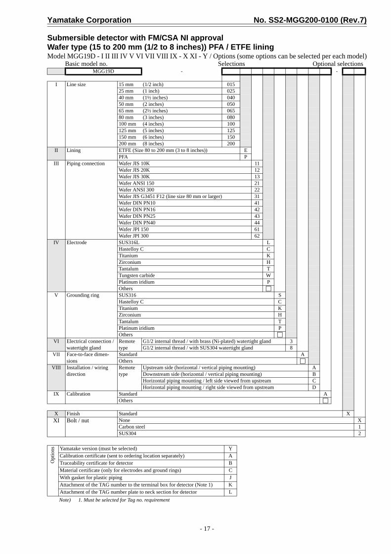
Submersible detector with FM/CSA NI approvalWafer type (15 to 200 mm (1/2 to 8 inches)) PFA / ETFE liningModel MGG19D - I II III IV V VI VII VIII IX - X XI - Y / Options (some options can be selected per each model)
Basic model no. Selections Optional selections
Note) 1. Must be selected for Tag no. requirement
MGG19D - -
I Line size 15 mm (1/2 inch) 01525 mm (1 inch) 02540 mm (1½ inches) 04050 mm (2 inches) 05065 mm (2½ inches) 06580 mm (3 inches) 080100 mm (4 inches) 100125 mm (5 inches) 125150 mm (6 inches) 150200 mm (8 inches) 200
II Lining ETFE (Size 80 to 200 mm (3 to 8 inches)) EPFA P
III Piping connection Wafer JIS 10K 11Wafer JIS 20K 12Wafer JIS 30K 13Wafer ANSI 150 21Wafer ANSI 300 22Wafer JIS G3451 F12 (line size 80 mm or larger) 31Wafer DIN PN10 41Wafer DIN PN16 42Wafer DIN PN25 43Wafer DIN PN40 44Wafer JPI 150 61Wafer JPI 300 62
IV Electrode SUS316L LHastelloy C CTitanium KZirconium HTantalum TTungsten carbide WPlatinum iridium POthers
V Grounding ring SUS316 SHastelloy C CTitanium KZirconium HTantalum TPlatinum iridium POthers
VI Electrical connection / watertight gland
Remote type
G1/2 internal thread / with brass (Ni-plated) watertight gland 3G1/2 internal thread / with SUS304 watertight gland 8
VII Face-to-face dimen-sions
Standard AOthers
VIII Installation / wiring direction
Remote type
Upstream side (horizontal / vertical piping mounting) ADownstream side (horizontal / vertical piping mounting) BHorizontal piping mounting / left side viewed from upstream CHorizontal piping mounting / right side viewed from upstream D
IX Calibration Standard AOthers
X Finish Standard XXI Bolt / nut None X
Carbon steel 1SUS304 2
Opt
ions Yamatake version (must be selected) Y
Calibration certificate (sent to ordering location separately) ATraceability certificate for detector BMaterial certificate (only for electrodes and ground rings) CWith gasket for plastic piping JAttachment of the TAG number to the terminal box for detector (Note 1) KAttachment of the TAG number plate to neck section for detector L

No. SS2-MGG200-0100 (Rev.7) Yamatake Corporation
- 18 -
Submersible detector with FM/CSA NI approvalFlange type (15 to 200 mm (1/2 to 8 inches)) PFA / ETFE liningModel MGG19F - I II III IV V VI VII VIII IX X - XI - Y / Options (some options can be selected per each model)
Basic model no. Selections Optional selections
Note) 1. Must be selected for Tag no. requirement
MGG19F - -
I Line size 15 mm (1/2 inch) 01525 mm (1 inch) 02540 mm (1½ inches) 04050 mm (2 inches) 05065 mm (2½ inches) 06580 mm (3 inches) 080100 mm (4 inches) 100125 mm (5 inches) 125150 mm (6 inches) 150200 mm (8 inches) 200
II Lining ETFE (Size 80 to 200 mm (3 to 8 inches)) EPFA P
III Piping connection Flange JIS 10K J1Flange JIS 20K J2Flange JIS 30K J3Flange ANSI 150 A1Flange ANSI 300 A2Flange JIS G3451 F12 (line size 80 mm or larger) G1Flange DIN PN10 D1Flange DIN PN16 D2Flange DIN PN25 D3Flange DIN PN40 D4Flange JPI 150 P1Flange JPI 300 P2
IV Flange material Standard 1Others
V Electrode SUS316L LHastelloy C CTitanium KZirconium HTantalum TTungsten carbide WPlatinum iridium POthers
VI Grounding ring SUS316 SHastelloy C CTitanium KZirconium HTantalum TPlatinum iridium POthers
VII Electrical connection / watertight gland
Remote type
G1/2 internal thread / with brass (Ni-plated) watertight gland 3G1/2 internal thread / with SUS304 watertight gland 8
VIII Face-to-face dimensions Standard AOthers
IX Installation / wiring direc-tion
Remote type
Upstream side (horizontal / vertical piping mounting) ADownstream side (horizontal / vertical piping mounting) BHorizontal piping mounting / left side viewed from upstream CHorizontal piping mounting / right side viewed from upstream D
X Calibration Standard AOthers
XI Finish Standard X
Opt
ions Yamatake version (must be selected) Y
Calibration certificate (sent to ordering location separately) ATraceability certificate for detector BMaterial certificate (only for electrodes and ground rings) CWith gasket for plastic piping JAttachment of the TAG number to the terminal box for detector (Note 1) KAttachment of the TAG number plate to neck section for detector L

Yamatake Corporation No. SS2-MGG200-0100 (Rev.7)
- 19 -
Submersible detector with FM/CSA NI approvalFlange type (250 to 600 mm (10 to 24 inches)) PFA / ETFE liningModel MGG19F - I II III IV V VI VII VIII IX X - XI - Y / Options (some options can be selected per each model)
Basic model no. Selections Optional selections
Note) 1. Must be selected for Tag no. requirement
MGG19F - -
I Line size 250 mm (10 inches) 250300 mm (12 inches) 300350 mm (14 inches) 350400 mm (16 inches) 400450 mm (18 inches) 450500 mm (20 inches) 500600 mm (24 inches) 600
II Lining ETFE EPFA P
III Piping connection Flange JIS 10K J1Flange JIS 20K J2Flange ANSI 150 A1Flange ANSI 300 (Size 16 inches or smaller) A2Flange JIS G3451 F12 G1Flange DIN PN10 D1Flange DIN PN16 D2Flange DIN PN25 D3Flange JPI 150 P1Flange JPI 300 (Size 400 mm or smaller) P2
IV Flange material Standard 1Others
V Electrode SUS316L LHastelloy C CTitanium KZirconium HTantalum TTungsten carbide WPlatinum iridium POthers
VI Grounding ring SUS316 SHastelloy C CTitanium KOthers
VII Electrical connection / watertight gland
Remote type
G1/2 internal thread / with brass (Ni-plated) watertight gland 3G1/2 internal thread / with SUS304 watertight gland 8
VIII Face-to-face dimensions Standard AOthers
IX Installation / wiring direc-tion
Remote type
Upstream side (horizontal / vertical piping mounting) ADownstream side (horizontal / vertical piping mounting) BHorizontal piping mounting / left side viewed from upstream CHorizontal piping mounting / right side viewed from upstream D
X Calibration Standard AOthers
XI Finish Standard X
Opt
ions Yamatake version (must be selected) Y
Calibration certificate (sent to ordering location separately) ATraceability certificate for detector BMaterial certificate (only for electrodes and ground rings) CWith gasket for plastic piping JAttachment of the TAG number to the terminal box for detector (Note 1) KAttachment of the TAG number plate to neck section for detector L

No. SS2-MGG200-0100 (Rev.7) Yamatake Corporation
- 20 -
Submersible detector with FM/CSA NI approvalWafer type (25 to 200 mm (1 to 8 inches)) Polyurethane rubber liningModel MGG19D - I II III IV V VI VII VIII IX - X XI - Y / Options (some options can be selected per each model)
Basic model no. Selections Optional selections
Note) 1. Must be selected for Tag no. requirement
MGG19D - -
I Line size 25 mm (1 inch) 02540 mm (1½ inches) 04050 mm (2 inches) 05065 mm (2½ inches) 06580 mm (3 inches) 080100 mm (4 inches) 100125 mm (5 inches) 125150 mm (6 inches) 150200 mm (8 inches) 200
II Lining Polyurethane rubber QIII Piping connection Wafer JIS 10K 11
Wafer JIS 20K 12Wafer JIS 30K 13Wafer ANSI 150 21Wafer ANSI 300 22Wafer JIS G3451 F12 (line size 80 mm or larger) 31Wafer DIN PN10 41Wafer DIN PN16 42Wafer DIN PN25 43Wafer DIN PN40 44Wafer JPI 150 61Wafer JPI 300 62
IV Electrode SUS316L LTitanium KTungsten carbide (only for size 10 mm) WOthers
V Grounding ring SUS316 STitanium KOthers
VI Electrical connection / watertight gland
Remote type
G1/2 internal thread / with brass (Ni-plated) watertight gland 3G1/2 internal thread / with SUS304 watertight gland 8
VII Face-to-face dimensions Standard AVIII Installation / wiring direc-
tionRemote type
Upstream side (horizontal / vertical piping mounting) ADownstream side (horizontal / vertical piping mounting) BHorizontal piping mounting / left side viewed from upstream CHorizontal piping mounting / right side viewed from upstream D
IX Calibration Standard AOthers
X Finish Standard XXI Bolt / nut None X
Carbon steel 1SUS304 2
Opt
ions Yamatake version (must be selected) Y
Calibration certificate (sent to ordering location separately) ATraceability certificate for detector BMaterial certificate (only for electrodes and ground rings) CWith gasket for plastic piping JAttachment of the TAG number to the terminal box for detector (Note 1) KAttachment of the TAG number plate to neck section for detector L

Yamatake Corporation No. SS2-MGG200-0100 (Rev.7)
- 21 -
Submersible detector with FM/CSA NI approvalFlange type (25 to 200 mm (1 to 8 inches)) Polyurethane rubber liningModel MGG19F - I II III IV V VI VII VIII IX X - XI - Y / Options (some options can be selected per each model)
Basic model no. Selections Optional selections
Note) 1. Must be selected for Tag no. requirement
MGG19F - -
I Line size 25 mm (1 inch) 02540 mm (1½ inches) 04050 mm (2 inches) 05065 mm (2½ inches) 06580 mm (3 inches) 080100 mm (4 inches) 100125 mm (5 inches) 125150 mm (6 inches) 150200 mm (8 inches) 200
II Lining Polyurethane rubber QIII Piping connection Flange JIS 10K J1
Flange JIS 20K J2Flange JIS 30K J3Flange ANSI 150 A1Flange ANSI 300 A2Flange JIS G3451 F12 (line size 80 mm or larger) G1Flange DIN PN10 D1Flange DIN PN16 D2Flange DIN PN25 D3Flange DIN PN40 D4Flange JPI 150 P1Flange JPI 300 P2
IV Flange material Standard 1V Electrode SUS316L L
Titanium KTungsten carbide WOthers
VI Grounding ring SUS316 STitanium KOthers
VII Electrical connection / watertight gland
Remote type
G1/2 internal thread / with brass (Ni-plated) watertight gland 3G1/2 internal thread / with SUS304 watertight gland 8
VIII Face-to-face dimensions Standard AIX Installation / wiring direc-
tionRemote type
Upstream side (horizontal / vertical piping mounting) ADownstream side (horizontal / vertical piping mounting) BHorizontal piping mounting / left side viewed from upstream CHorizontal piping mounting / right side viewed from upstream D
X Calibration Standard AOthers
XI Finish Standard X
Opt
ions Yamatake version (must be selected) Y
Calibration certificate (sent to ordering location separately) ATraceability certificate for detector BMaterial certificate (only for electrodes and ground rings) CWith gasket for plastic piping JAttachment of the TAG number to the terminal box for detector (Note 1) KAttachment of the TAG number plate to neck section for detector L
No. SS2-MGG200-0100 (Rev.7) Yamatake Corporation
- 22 -
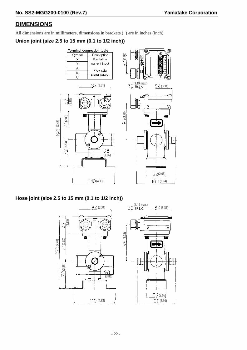
DIMENSIONSAll dimensions are in millimeters, dimensions in brackets ( ) are in inches (inch).
Union joint (size 2.5 to 15 mm (0.1 to 1/2 inch))
Hose joint (size 2.5 to 15 mm (0.1 to 1/2 inch))
(3.31)
(1.85
)(2
.80)
(2.83
)
(7.48
)
(3.86)
(4.33) (3.94)
(2.05)
(3.78
)
(3.31)(1.19 max.)
(1.97
)
(3.31)
(1.85
)(2
.80)
(2.83
)
(7.48
)
(3.86)
(4.33)
(3.78
)
(1.19 max.)(3.31)
(2.05)(3.94)
Yamatake Corporation No. SS2-MGG200-0100 (Rev.7)
- 23 -
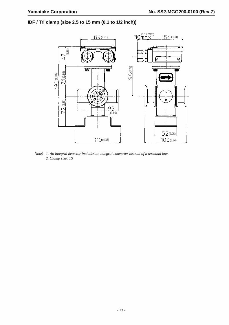
IDF / Tri clamp (size 2.5 to 15 mm (0.1 to 1/2 inch))
Note) 1. An integral detector includes an integral converter instead of a terminal box.2. Clamp size: 1S
(3.31)
(1.85
)(2
.80)
(2.83
)
(7.48
)
(3.86)
(4.33)
(3.78
)
(1.19 max.)(3.31)
(2.05)
(3.94)
No. SS2-MGG200-0100 (Rev.7) Yamatake Corporation
- 24 -
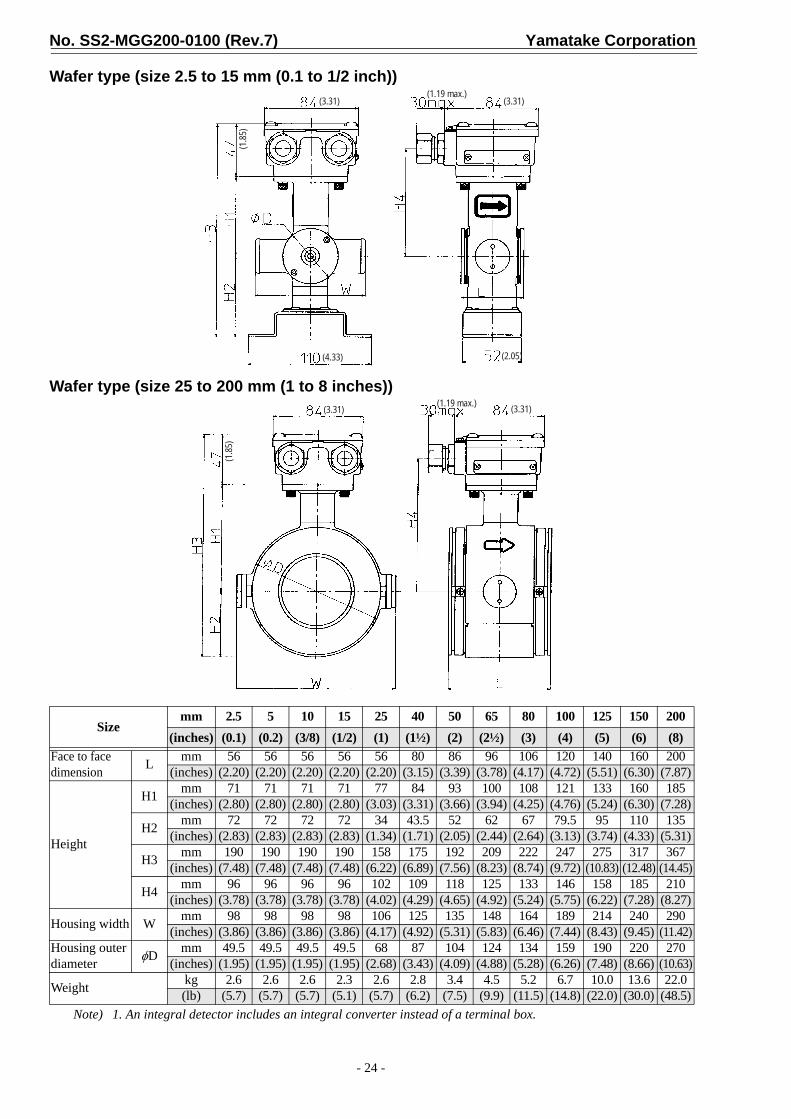
Wafer type (size 2.5 to 15 mm (0.1 to 1/2 inch))
Wafer type (size 25 to 200 mm (1 to 8 inches))
Note) 1. An integral detector includes an integral converter instead of a terminal box.
Sizemm 2.5 5 10 15 25 40 50 65 80 100 125 150 200
(inches) (0.1) (0.2) (3/8) (1/2) (1) (1½) (2) (2½) (3) (4) (5) (6) (8)Face to face dimension L mm 56 56 56 56 56 80 86 96 106 120 140 160 200
(inches) (2.20) (2.20) (2.20) (2.20) (2.20) (3.15) (3.39) (3.78) (4.17) (4.72) (5.51) (6.30) (7.87)
Height
H1 mm 71 71 71 71 77 84 93 100 108 121 133 160 185(inches) (2.80) (2.80) (2.80) (2.80) (3.03) (3.31) (3.66) (3.94) (4.25) (4.76) (5.24) (6.30) (7.28)
H2 mm 72 72 72 72 34 43.5 52 62 67 79.5 95 110 135(inches) (2.83) (2.83) (2.83) (2.83) (1.34) (1.71) (2.05) (2.44) (2.64) (3.13) (3.74) (4.33) (5.31)
H3 mm 190 190 190 190 158 175 192 209 222 247 275 317 367(inches) (7.48) (7.48) (7.48) (7.48) (6.22) (6.89) (7.56) (8.23) (8.74) (9.72) (10.83) (12.48) (14.45)
H4 mm 96 96 96 96 102 109 118 125 133 146 158 185 210(inches) (3.78) (3.78) (3.78) (3.78) (4.02) (4.29) (4.65) (4.92) (5.24) (5.75) (6.22) (7.28) (8.27)
Housing width W mm 98 98 98 98 106 125 135 148 164 189 214 240 290(inches) (3.86) (3.86) (3.86) (3.86) (4.17) (4.92) (5.31) (5.83) (6.46) (7.44) (8.43) (9.45) (11.42)
Housing outer diameter φD mm 49.5 49.5 49.5 49.5 68 87 104 124 134 159 190 220 270
(inches) (1.95) (1.95) (1.95) (1.95) (2.68) (3.43) (4.09) (4.88) (5.28) (6.26) (7.48) (8.66) (10.63)
Weight kg 2.6 2.6 2.6 2.3 2.6 2.8 3.4 4.5 5.2 6.7 10.0 13.6 22.0(lb) (5.7) (5.7) (5.7) (5.1) (5.7) (6.2) (7.5) (9.9) (11.5) (14.8) (22.0) (30.0) (48.5)
(3.31) (3.31)(1.19 max.)
(1.85
)
(4.33) (2.05)
(3.31) (3.31)(1.19 max.)
(1.85
)

Yamatake Corporation No. SS2-MGG200-0100 (Rev.7)
- 25 -
Flange type (size 2.5 to 15 mm (0.1 to 1/2 inch))
Flange type (size 25 mm (1 inch))
Note) 1. This table is for remote detectors.2. An integral detector includes an integral converter instead of a terminal box.3. The table indicates dimensions for ANSI 150 flange.
Sizemm 2.5 5 10 15 25
(inches) (0.1) (0.2) (3/8) (1/2) (1)
Face to face dimension L mm 160 160 160 200 200(inches) (6.30) (6.30) (6.30) (7.87) (7.87)
Height
H1 mm 71 71 71 71 77(inches) (2.80) (2.80) (2.80) (2.80) (3.03)
H2 mm 72 72 72 72 54(inches) (2.83) (2.83) (2.83) (2.83) (2.13)
H3 mm 190 190 190 190 178(inches) (7.48) (7.48) (7.48) (7.48) (7.01)
H4 mm 96 96 96 96 102(inches) (3.78) (3.78) (3.78) (3.78) (4.02)
Width W mm 98 98 98 98 106(inches) (3.86) (3.86) (3.86) (3.86) (4.17)
Weight kg 5.0 5.0 5.0 5.0 6.6(lb) (11.0) (11.0) (11.0) (11.0) (14.6)
(3.31) (3.31)(1.19 max.)
(1.85
)
(4.33)
(2.05)
(3.31) (3.31)(1.19 max.)
(1.85
)

No. SS2-MGG200-0100 (Rev.7) Yamatake Corporation
- 26 -
Flange type (size 40 to 100 mm (1½ to 4 inches))
Flange type (size 150 to 600 mm (6 to 24 inches))
Note) 1. This table is for remote detectors.2. An integral detector includes an integral converter instead of a terminal box.3. The table indicates dimensions for ANSI 150 flange.
Sizemm 40 50 65 80 100 125 150 200 250 300 350 400 450 500 600
(inches) (1½) (2) (2½) (3) (4) (5) (6) (8) (10) (12) (14) (16) (18) (20) (24)Face to face dimension L mm 200 200 200 200 250 250 300 350 450 500 550 600 600 600 650
(inches) (7.87) (7.87) (7.87) (7.87) (9.84) (9.84) (11.81) (13.78) (17.72) (19.69) (21.65) (23.62) (23.62) (23.62) (25.59)
Height
H1 mm 84 93 100 108 121 133 160 185 235 258 282 310 339 366 415(inches) (3.31) (3.66) (3.94) (4.25) (4.76) (5.24) (6.30) (7.28) (9.25) (10.16) (11.10) (12.20) (13.35) (14.41) (16.34)
H2 mm 77 88 103 113 131 145 174 204 224 271 297 340 364 396 456(inches) (3.03) (3.46) (4.06) (4.45) (5.16) (5.71) (6.85) (8.03) (8.82) (10.67) (11.09) (13.39) (14.33) (15.59) (17.95)
H3 mm 208 228 250 268 299 325 381 436 506 576 626 697 750 809 918(inches) (8.19) (8.98) (9.84) (10.55) (11.77) (12.80) (15.0) (17.17) (19.92) (22.68) (24.65) (27.44) (29.53) (31.85) (36.14)
H4 mm 109 118 125 133 146 158 185 210 260 283 307 335 364 391 440(inches) (4.29) (4.65) (4.92) (5.24) (5.75) (6.22) (7.28) (8.27) (10.24) (11.14) (12.09) (13.19) (14.33) (15.39) (17.32)
Weight (kg) kg 6.0 10.5 12.5 15.5 23.3 32.0 35.4 60.0 68.0 97.0 128 163 213 249 339(lb) (13.2) (23.1) (27.6) (34.2) (51.4) (70.5) (78.0) (132) (150) (214) (282) (359) (470) (549) (747)
(3.31)
(1.85
)
(3.31)(1.19 max.)
(3.31) (3.31)(1.19 max.)
(1.85
)

Yamatake Corporation No. SS2-MGG200-0100 (Rev.7)
- 27 -
Flange type (size 700 to 900 mm (28 to 36 inches))
Flange type (size 1000, 1100 mm (40, 44 inches))
Note) The table indicates dimensions for ANSI 150 flange.*: n = number, d = diameter
Sizemm 700 800 900 1000 1100
(inches) (28) (32) (36) (40) (44)Face to face dimension L
mm 1100 1200 1300 1500 1500(inches) (43.31) (47.24) (51.18) (59.06) (59.06)
Height
Hmm 979 1080 1211 1278 1399
(inches) (38.54) (42.52) (47.68) (50.31) (55.08)
H1mm 503 554 634 650 720
(inches) (19.80) (21.81) (24.96) (25.59) (28.35)
H2mm 429 480 530 581 632
(inches) (16.89) (18.90) (20.87) (22.87) (24.88)
H3mm 454 505 555 606 657
(inches) (17.87) (19.88) (21.85) (23.86) (25.87)
Feet length Wmm 1049 1145 1245 980 1000
(inches) (41.30) (45.08) (49.02) (38.58) (39.37)
Feet width Amm 600 600 600 800 800
(inches) (23.62) (23.62) (23.62) (31.50) (31.50)
Feet halls * n-φdmm 4-φ33 4-φ33 4-φ33 4-φ33 4-φ33
(inches) (1.30) (1.30) (1.30) (1.30) (1.30)
Weightkg 630.0 720.0 1060.0 1320.0 1540.0(lb) (1389) (1587) (2337) (2910) (3395)
H

Totate international Building2-12-19 ShibuyaShibuya-ku, Tokyo 150-8316JapanTel :Fax :
81-3-3486-231081-3-3486-2593
This has been printed on recycled paper.http://www.yamatake.com/
SavemationSaving through Automation