detection and segmentation of mirror-like surfaces using ... · pdf fileby illuminating the...
TRANSCRIPT

Detection and Segmentation of Mirror-like Surfaces UsingStructured Illumination
Rajat Aggarwal Anoop M. Namboodiri
Kohli Center on Intelligent Systems,International Institute of Information Technology- Hyderabad, India.
{rajat.aggarwal@research., anoop@}iiit.ac.in
ABSTRACTIn computer vision, many active illumination techniques em-ploy Projector-Camera systems to extract useful informationfrom the scenes. Known illumination patterns are projectedonto the scene and their deformations in the captured im-ages are then analyzed. We observe that the local frequen-cies in the captured pattern for the mirror-like surfaces isdifferent from the projected pattern. This property allowsus to design a custom Projector-Camera system to segmentmirror-like surfaces by analyzing the local frequencies in thecaptured images. The system projects a sinusoidal patternand capture the images from projector’s point of view. Wepresent segmentation results for the scenes including multi-ple reflections and inter-reflections from the mirror-like sur-faces. The method can further be used in the separationof direct and global components for the mirror-like surfacesby illuminating the non-mirror-like objects separately. Weshow how our method is also useful for accurate estimationof shape of the non-mirror-like regions in the presence ofmirror-like regions in a scene.
CCS Concepts•Computing methodologies → Computational pho-tography; Image processing;
KeywordsStructured Illumination; Mirror-like surfaces, Segmentation,Projector- Camera
1. INTRODUCTIONStructured light systems are widely used in applications
such as machine vision, visual inspection, parts alignment,object recognition, estimating material properties, 3D scan-ners, space time stereos etc. However, capturing reliableinformation from a very complex scene including wide rangeof shapes and materials, is a difficult task. One of thesecomplicated surfaces are mirror like surfaces. Mirror like
Permission to make digital or hard copies of all or part of this work for personal orclassroom use is granted without fee provided that copies are not made or distributedfor profit or commercial advantage and that copies bear this notice and the full cita-tion on the first page. Copyrights for components of this work owned by others thanACM must be honored. Abstracting with credit is permitted. To copy otherwise, or re-publish, to post on servers or to redistribute to lists, requires prior specific permissionand/or a fee. Request permissions from [email protected].
ICVGIP ’16 Guwahati, Assam Indiac© 2016 ACM. ISBN 978-1-4503-4753-2/16/12. . . $15.00
DOI: http://dx.doi.org/10.1145/3009977.3010020
(a) (b)
(c) (d)
Figure 1: (a)Captured image with sinusoidal pattern projectedonto the scene from projector’s point of view. (b)Binary imagerepresenting the windows which are labelled as the specular re-gions. (c)Smooth segmentation obtained by applying MRF usingInitial segmentation cues (d)Color Image of the specular regionspresent in the scene.
surfaces are common objects in vision tasks and robot nav-igation. They are commonly found in indoor environmentsand its difficult to recognise for a camera whether it is an ob-stacle or a path. As service robots perform more and moretasks in indoor environments, the ability to recognize mir-rors is necessary. In vision, these objects poses a problemfor all techniques that are based on feature detection andmatching, such as, binocular stereo and Structure from Mo-tion. This is because, the appearance of mirror-like objectsdepends upon the environment and thus, it is difficult to de-termine whether an image feature corresponds to an actualscene point or it is the specular reflection of another scenepoint. The representation of mirror-like surfaces dependsnot only on the surface properties but also on the propertiesof the surrounding scene and the viewpoint of the observer.One of the solutions to remove these kind of inaccuraciesis to apply separate robust techniques for different surfacematerials. This makes segmentation of mirror-like surfacesan important problem. Detection of mirror-like surfaces ina scene, can simplify pre-processing steps in many practicaltasks in robotic vision algorithms.
In this work, we present an active illumination techniquefor segmentation of mirror-like surfaces from the scene. Wepropose a custom setup consisting of a camera, projectorand a One-Way mirror which is used to capture the pat-tern projected onto the scene from the projector’s point ofview. It is observed that the captured frequency of the il-lumination pattern for the specular surfaces, changes whenviewed at a distance from projection point. These changesin local frequencies are exploited to segment out the specu-lar regions in the imaged scene. Fig 1a shows the image ofthe scene captured using our setup from projector’s point ofview. Changes in the local frequencies are used to segmentthe specular regions as shown in Fig 1b. The setup ensuresthat the change is only due to the nature of the materialand not due to the shape and orientation of the objects inthe scene.
The major contribution of our work is to provide a customsetup using which we can image the scene from the projec-tor’s point of view. The second contribution of this workis to detect the frequency change in the projected and theobserved illumination pattern and use this difference as acue for segmenting out the mirror like regions. We show ex-periments on various scenes including mirrors and partiallyspecular objects. We then demonstrate the usefulness of thesegmentation to correctly separate out the direct and indi-rect illumination for the specular objects in a scene. Finally,we point out that this method can be employed to accuratelyreconstruct the surface if separate robust techniques are ap-plied for different kind of surfaces.
2. RELATED WORKThere has been a lot of work on removing specularity
(highlights) from the image as shown in [3] but only a smallnumber of researchers have looked into the issue of detect-ing specular surfaces and correcting the errors automatically.People have used different sensors to detect mirrors and win-dows , used the information from the surrounding to detectthe feature points and the specular highlights to recognizespecular surfaces.
Yang and Wang [26, 27] introduced a sensor fusion tech-nique to detect potential mirror-like obstacles in a 2D oc-cupancy grid map using sonar sensors and a laser scanner.However, their approach works in 2D only. Koch et. al. [11]presented a specular reflectance detection approach applica-ble to multi-echo laser scanners in order to identify and fil-ter mirrored objects. Agha-mohammadi and Song [2] and Luet.al. [15] proposed a technique of estimating a mirror trans-formation matrix and geometric constraints for correspond-ing real and virtual feature points in the image. However,these approaches assume the presence of feature points fromthe surroundings as well as their mirror images in the cap-tured scene. Our technique assumes no prior environmentinformation to detect the mirror-like surfaces. Kashammerand nuchter [9] captures a series of 3D laser scans. Lasercompletely gets reflected when strikes the mirror surface anddo not appear in the point cloud at all. However, this is ap-plicable only for framed rectangular mirrors whose dimen-sions are known.
Other approaches are based on the information from theenvironment to detect the distortions in a known shape.Oren and Nayar [19] analyze the characteristic and gov-erning geometry of specular surfaces. However, their pro-posed method is limited to surfaces with high curvature and
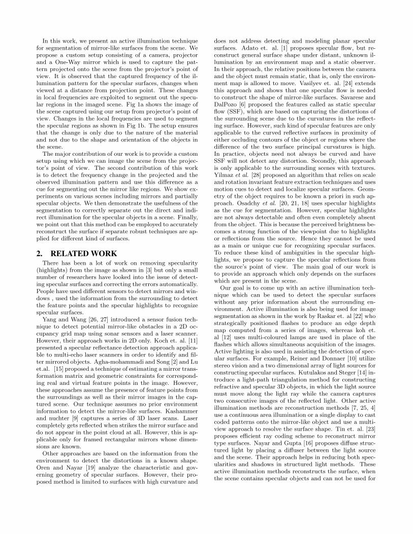
does not address detecting and modeling planar specularsurfaces. Adato et. al. [1] proposes specular flow, but re-construct general surface shape under distant, unknown il-lumination by an environment map and a static observer.In their approach, the relative positions between the cameraand the object must remain static, that is, only the environ-ment map is allowed to move. Vasilyev et. al. [24] extendsthis approach and shows that one specular flow is neededto construct the shape of mirror-like surfaces. Savarese andDalPozo [6] proposed the features called as static specularflow (SSF), which are based on capturing the distortions ofthe surrounding scene due to the curvatures in the reflect-ing surface. However, such kind of specular features are onlyapplicable to the curved reflective surfaces in proximity ofeither occluding contours of the object or regions where thedifference of the two surface principal curvatures is high.In practice, objects need not always be curved and haveSSF will not detect any distortion. Secondly, this approachis only applicable to the surrounding scenes with textures.Yilmaz et al. [28] proposed an algorithm that relies on scaleand rotation invariant feature extraction techniques and usesmotion cues to detect and localize specular surfaces. Geom-etry of the object requires to be known a priori in such ap-proach. Osadchy et al. [20, 21, 18] uses specular highlightsas the cue for segmentation. However, specular highlightsare not always detectable and often even completely absentfrom the object. This is because the perceived brightness be-comes a strong function of the viewpoint due to highlightsor reflections from the source. Hence they cannot be usedas a main or unique cue for recognizing specular surfaces.To reduce these kind of ambiguities in the specular high-lights, we propose to capture the specular reflections fromthe source’s point of view. The main goal of our work isto provide an approach which only depends on the surfaceswhich are present in the scene.
Our goal is to come up with an active illumination tech-nique which can be used to detect the specular surfaceswithout any prior information about the surrounding en-vironment. Active illumination is also being used for imagesegmentation as shown in the work by Raskar et. al [22] whostrategically positioned flashes to produce an edge depthmap computed from a series of images, whereas koh et.al [12] uses multi-coloured lamps are used in place of theflashes which allows simultaneous acquisition of the images.Active lighting is also used in assisting the detection of spec-ular surfaces. For example, Reiner and Donnaer [10] utilizestereo vision and a two dimensional array of light sources forconstructing specular surfaces. Kutulakos and Steger [14] in-troduce a light-path triangulation method for constructingrefractive and specular 3D objects, in which the light sourcemust move along the light ray while the camera capturestwo consecutive images of the reflected light. Other activeillumination methods are reconstruction methods [7, 25, 4]use a continuous area illumination or a single display to castcoded patterns onto the mirror-like object and use a multi-view approach to resolve the surface shape. Tin et. al. [23]proposes efficient ray coding scheme to reconstruct mirrortype surfaces. Nayar and Gupta [16] proposes diffuse struc-tured light by placing a diffuser between the light sourceand the scene. Their approach helps in reducing both spec-ularities and shadows in structured light methods. Theseactive illumination methods reconstructs the surface, whenthe scene contains specular objects and can not be used for
(a)
dP
O
Mirror-like Surface
Diffuse Surface
f
E
F
BACD
L
M
(b)
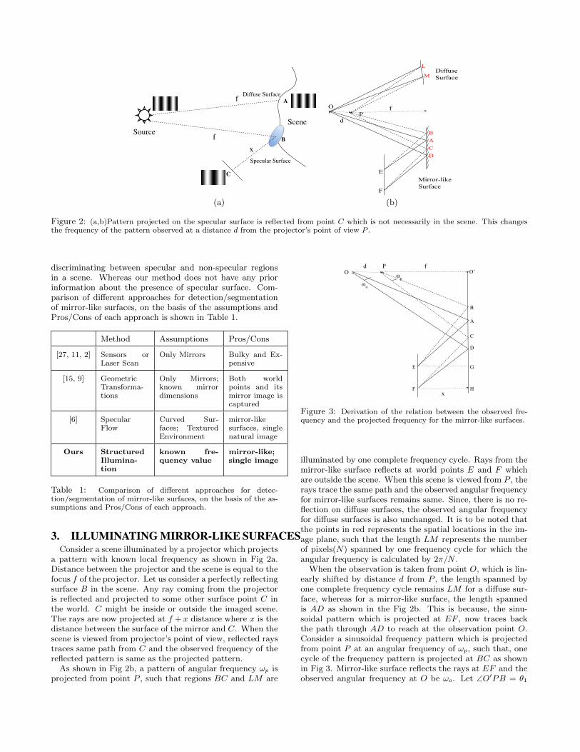
Figure 2: (a,b)Pattern projected on the specular surface is reflected from point C which is not necessarily in the scene. This changesthe frequency of the pattern observed at a distance d from the projector’s point of view P .
discriminating between specular and non-specular regionsin a scene. Whereas our method does not have any priorinformation about the presence of specular surface. Com-parison of different approaches for detection/segmentationof mirror-like surfaces, on the basis of the assumptions andPros/Cons of each approach is shown in Table 1.
Method Assumptions Pros/Cons
[27, 11, 2] Sensors orLaser Scan
Only Mirrors Bulky and Ex-pensive
[15, 9] GeometricTransforma-tions
Only Mirrors;known mirrordimensions
Both worldpoints and itsmirror image iscaptured
[6] SpecularFlow
Curved Sur-faces; TexturedEnvironment
mirror-likesurfaces, singlenatural image
Ours StructuredIllumina-tion
known fre-quency value
mirror-like;single image
Table 1: Comparison of different approaches for detec-tion/segmentation of mirror-like surfaces, on the basis of the as-sumptions and Pros/Cons of each approach.
3. ILLUMINATING MIRROR-LIKE SURFACESConsider a scene illuminated by a projector which projects
a pattern with known local frequency as shown in Fig 2a.Distance between the projector and the scene is equal to thefocus f of the projector. Let us consider a perfectly reflectingsurface B in the scene. Any ray coming from the projectoris reflected and projected to some other surface point C inthe world. C might be inside or outside the imaged scene.The rays are now projected at f + x distance where x is thedistance between the surface of the mirror and C. When thescene is viewed from projector’s point of view, reflected raystraces same path from C and the observed frequency of thereflected pattern is same as the projected pattern.
As shown in Fig 2b, a pattern of angular frequency ωp isprojected from point P , such that regions BC and LM are
d PO
f
B
A
C
D
E
Fx
O’
ωo
⍵p
G
H
Figure 3: Derivation of the relation between the observed fre-quency and the projected frequency for the mirror-like surfaces.
illuminated by one complete frequency cycle. Rays from themirror-like surface reflects at world points E and F whichare outside the scene. When this scene is viewed from P , therays trace the same path and the observed angular frequencyfor mirror-like surfaces remains same. Since, there is no re-flection on diffuse surfaces, the observed angular frequencyfor diffuse surfaces is also unchanged. It is to be noted thatthe points in red represents the spatial locations in the im-age plane, such that the length LM represents the numberof pixels(N) spanned by one frequency cycle for which theangular frequency is calculated by 2π/N .
When the observation is taken from point O, which is lin-early shifted by distance d from P , the length spanned byone complete frequency cycle remains LM for a diffuse sur-face, whereas for a mirror-like surface, the length spannedis AD as shown in the Fig 2b. This is because, the sinu-soidal pattern which is projected at EF , now traces backthe path through AD to reach at the observation point O.Consider a sinusoidal frequency pattern which is projectedfrom point P at an angular frequency of ωp, such that, onecycle of the frequency pattern is projected at BC as shownin Fig 3. Mirror-like surface reflects the rays at EF and theobserved angular frequency at O be ωo. Let ∠O′PB = θ1

f-xx
x+d
Figure 4: Camera-projector alignment for capturing imagesfrom projector’s point of view using One-way mirror. Rays passthrough the One-way mirror and gets reflected back from pointP in the direction of the camera. Camera is at distance d andcaptures the image from projector’s point of view.
and ∠O′OA = θ2, such that
O′B
f= tan θ1,
O′B +BC
f= tan (θ1 + ωp) (1)
From observation point O, we get
O′B +BA
f + d= tan θ2,
O′B +BA+AD
f + d= tan (θ2 + ωo)
(2)Also, from 4AEG and 4BEG, AB = x(tan θ1 − tan θ2),from4CFH and4DFH, CD = x(tan (θ1 + ωp)−tan (θ2 + ωo))Solving these equations we get,
ωo = arctan
(tanωp
(f + x
d+ f + x
))(3)
As d increases, ωo decreases and CD > BA. From Fig3, AD = AC + CD and BC = BA + AC, which impliesAD > BC. Therefore, when an illumination pattern withknown local frequency is projected onto the scene and im-age is the captured at a distance from projector’s imagingplane, the observed local frequency of the projected patternis changed. Whereas for non-mirror-like regions, capturedfrequency remains equal to the projected frequency ideally.It must be noted that the frequency change is primarly dueto change of depth, when observing mirror lke surface be-cause it focus at some other point in the world. Also, theanalysis holds for both flat and curved surfaces given thatthe projector and camera are coaxial. In next section, weshow the custom projector-camera setup to capture the im-age from observation point O.
3.1 System Setup and Illumination PatternTo implement the mentioned approach, we designed a
Projector-Camera setup as shown in Fig 4, which is usedto capture the image from the projector’s point of view. Toachieve this, we use a ‘One-Way Mirror ’ (A one-way mirrorhas a reflective coating applied in a very thin and sparselayer. It is also called as half-silvered surface) in betweenthe projector and the scene such that all the rays projectingfrom the projector passes through the one-way mirror andthen illuminates the scene. We use this property to capturethe image from exact projector’s point of view by keepingthe camera perpendicular to the projector’s direction. Anyray coming from the projector hits the object present in the
scene and is reflected back in the one-way mirror by tracingthe exact same path.
In case when one side of the one-way mirror is brightlylit and the other is dark, it allows viewing from the darkside but not vice versa. Thus, the camera only captures thescene which is in front of the one-way mirror and not theother side of the mirror. In order to capture the image frompoint O, camera is placed at a distance x+ d from One-waymirror. All the projected rays trace back at the same focuspoint when d = 0 and camera behaves as if looking fromprojector’s point of view P . Height of the camera and theprojector should be same. The benefit of such a setup isthat we are restricted to one single and fixed viewpoint andthe analysis of our algorithm is done using one single view-point. Otherwise for the mirror-like surfaces, the reflectionsand the perceived image is a function of viewpoint and theenvironment illumination. Also, the setup ensures that thechange is only due to the nature of the material and not dueto the shape and orientation of the objects in the scene.
4. SEGMENTATION BY ILLUMINATION
4.1 Local Frequency AnalysisIn the proposed setup consisting of a perspective cam-
era and a perspective projector, which projects a sinusoidalpattern onto the scene. We used the pattern f(x, y) =h2
[1 + cos(ω1x + ω2y)], where ω1 and ω2 are the angularfrequencies on the sinusoids in radians per pixel, and h isthe amplitude of the pattern.
Fig 1a shows the captured image of the scene illuminatedby a sinusoidal pattern. Consider an image captured fromthe proposed setup. As already discussed, regions where thelocal frequencies are increased or decreased by some amountin comparison to the actual projected frequencies of the pat-tern gives a simple cue to the mirror-like surfaces. To findthe cues for such regions we apply Short Time Fourier Trans-form on the whole image. We take small windows of size wslided by size s. For each response in the sliding window, wefirstly suppress the DC component of the response and findthe frequency peaks in the response. Since the actual pro-jected frequency is known, for the windows which have theresponse is equal to the actual frequency is labelled as thenon-mirror-like windows as shown in Fig 1b. These cues areused as the initial segmentation for the mirror-like regions.However, the second maximum peak after the DC compo-nent is suppressed will be for the actual pattern projected.If it is not the case then the maximum frequency will be forsome other pattern which might be due to the texture of theobject or the some other inter reflections. Inter-reflectionsare discussed in detail in next section.
4.2 MRF for surface segmentationWe use Markov Random Field (MRF) approach to accu-
rately find the mirror-like boundaries for better segmenta-tion results as shown in Fig 1c. Image is considered as arectangular grid of pixels and MRF is created by computingan energy function consisting of data term Ed and smooth-ness term Es, such as E(u) = Ed(u) + Es(u) where
Ed(u) = −∑i
log p(ui|zi)
Es(u) =∑i,j∈N
exp(||zi − zj ||2)
(a)
(b)
(c)
(d)
(e)
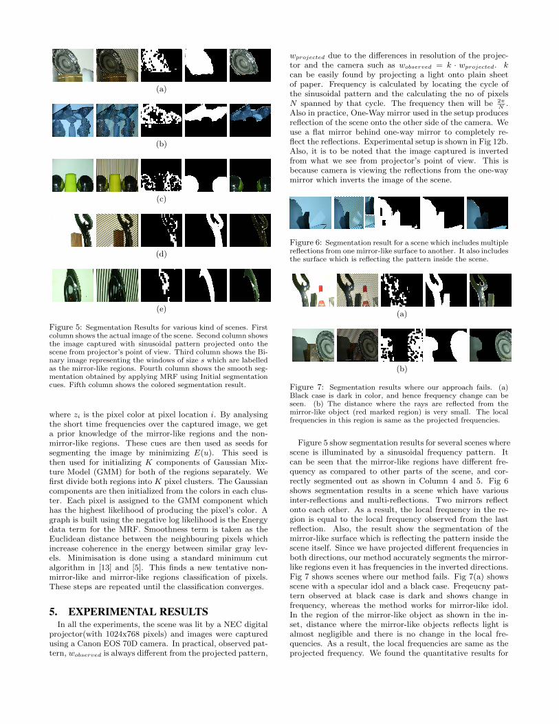
Figure 5: Segmentation Results for various kind of scenes. Firstcolumn shows the actual image of the scene. Second column showsthe image captured with sinusoidal pattern projected onto thescene from projector’s point of view. Third column shows the Bi-nary image representing the windows of size s which are labelledas the mirror-like regions. Fourth column shows the smooth seg-mentation obtained by applying MRF using Initial segmentationcues. Fifth column shows the colored segmentation result.
where zi is the pixel color at pixel location i. By analysingthe short time frequencies over the captured image, we geta prior knowledge of the mirror-like regions and the non-mirror-like regions. These cues are then used as seeds forsegmenting the image by minimizing E(u). This seed isthen used for initializing K components of Gaussian Mix-ture Model (GMM) for both of the regions separately. Wefirst divide both regions into K pixel clusters. The Gaussiancomponents are then initialized from the colors in each clus-ter. Each pixel is assigned to the GMM component whichhas the highest likelihood of producing the pixel’s color. Agraph is built using the negative log likelihood is the Energydata term for the MRF. Smoothness term is taken as theEuclidean distance between the neighbouring pixels whichincrease coherence in the energy between similar gray lev-els. Minimisation is done using a standard minimum cutalgorithm in [13] and [5]. This finds a new tentative non-mirror-like and mirror-like regions classification of pixels.These steps are repeated until the classification converges.
5. EXPERIMENTAL RESULTSIn all the experiments, the scene was lit by a NEC digital
projector(with 1024x768 pixels) and images were capturedusing a Canon EOS 70D camera. In practical, observed pat-tern, wobserved is always different from the projected pattern,
wprojected due to the differences in resolution of the projec-tor and the camera such as wobserved = k · wprojected. kcan be easily found by projecting a light onto plain sheetof paper. Frequency is calculated by locating the cycle ofthe sinusoidal pattern and the calculating the no of pixelsN spanned by that cycle. The frequency then will be 2π
N.
Also in practice, One-Way mirror used in the setup producesreflection of the scene onto the other side of the camera. Weuse a flat mirror behind one-way mirror to completely re-flect the reflections. Experimental setup is shown in Fig 12b.Also, it is to be noted that the image captured is invertedfrom what we see from projector’s point of view. This isbecause camera is viewing the reflections from the one-waymirror which inverts the image of the scene.
Figure 6: Segmentation result for a scene which includes multiplereflections from one mirror-like surface to another. It also includesthe surface which is reflecting the pattern inside the scene.
(a)
(b)
Figure 7: Segmentation results where our approach fails. (a)Black case is dark in color, and hence frequency change can beseen. (b) The distance where the rays are reflected from themirror-like object (red marked region) is very small. The localfrequencies in this region is same as the projected frequencies.
Figure 5 show segmentation results for several scenes wherescene is illuminated by a sinusoidal frequency pattern. Itcan be seen that the mirror-like regions have different fre-quency as compared to other parts of the scene, and cor-rectly segmented out as shown in Column 4 and 5. Fig 6shows segmentation results in a scene which have variousinter-reflections and multi-reflections. Two mirrors reflectonto each other. As a result, the local frequency in the re-gion is equal to the local frequency observed from the lastreflection. Also, the result show the segmentation of themirror-like surface which is reflecting the pattern inside thescene itself. Since we have projected different frequencies inboth directions, our method accurately segments the mirror-like regions even it has frequencies in the inverted directions.Fig 7 shows scenes where our method fails. Fig 7(a) showsscene with a specular idol and a black case. Freqeucny pat-tern observed at black case is dark and shows change infrequency, whereas the method works for mirror-like idol.In the region of the mirror-like object as shown in the in-set, distance where the mirror-like objects reflects light isalmost negligible and there is no change in the local fre-quencies. As a result, the local frequencies are same as theprojected frequency. We found the quantitative results for
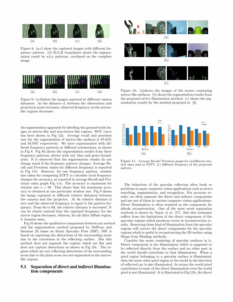
(a) (b) (c) (d)
Figure 8: (a-c) show the captured images with different fre-quency pattern. (d) R,G,B boundaries shows the segmen-tation result by a,b,c patterns, overlayed on the completeimage.
(a) (b) (c) (d)
Figure 9: (a-d)show the images captured at different cameradistances. As the distance d, between the observation andprojection point increases, observed frequency on the mirror-like regions decreases.
the segmentation approach by labelling the ground truth im-ages as mirror-like and non-mirror-like regions. ROC curvehas been shown in Fig 12a. Average recall and precisionrate for the segmentation of mirror-like surfaces is 97.64%and 93.50% respectively. We have experimented with dif-ferent frequency patterns at different orientations, as shownin Fig 8. Fig 8d shows the segmentation results from threefrequency patterns, shown with red, blue and green bound-aries. It is observed that the segmentation results do notchange much if the frequency pattern changes. Average Re-call and Precision values for different frequency is reportedin Fig 11b. However, for one frequency pattern, windowsize taken for computing STFT to calculate local frequencychanges the accuracy, as reported in average Recall and Pre-cision value graph Fig 11a. The accuracy is maximum forwindow size s = 50. This shows that the maximum accu-racy is obtained at one particular window size. Fig 9 showsthe image captured at different relative distances betweenthe camera and the projector. At 9a relative distance iszero and the observed frequency is equal to the pattern fre-quency. From 9a to 9d, the relative distance is increased. Itcan be clearly noticed that the captured frequency for themirror region decreases, whereas, for all other diffuse region,it remains same.
Fig 10 shows the qualitative comparison between our methodand the segmentation method proposed by DelPozo andSavarese [6] bases on Static Specular Flow (SSF). SSF isbased on capturing the distortions of the surrounding scenedue to the curvatures in the reflecting surface. But thismethod does not segment the regions which are flat anddoes not capture distortions as shown in Fig 10c. The re-gions which are not reflecting distortions of the surroundingscene due to the plain scene are not segmented as the mirror-like regions.
5.1 Separation of direct and indirect illumina-tion components
(a)
(b)
(c)
Figure 10: (a)shows the images of the scenes containingmirror-like surfaces. (b) shows the segmentation results fromthe proposed active illumination method. (c) shows the seg-mentation results by the method proposed in [6].
(a) (b)
Figure 11: Average Recall/ Precision graph for (a)different win-dow sizes used in STFT. (c) different frequency of the projectedpattern.
The behaviour of the specular reflection often leads toproblems in many computer vision applications such as stereomatching, segmentation, and recognition. For accurate re-sults, we often separate the direct and indirect componentsand use one of them in various computer vision applications.Direct illumination is often required as the component foralbedo reconstruction. One of the most novel separationmethods is shown by Nayar et al. [17]. But this techniquesuffers from the limitations of the direct component of thespecular regions which produces errors in reconstruction re-sults. Removing these kind of illumination from the specularregions will correct the direct components for the specularregions which is useful in reconstructing the 3D surface usingShape from Shading methods.
Consider the scene consisting of specular surfaces in it.Direct component is the illumination which is supposed tobe reflected directly from the surface and no other part inthe world should contribute to that illumination. When apixel region belonging to a specular surface is illuminated,then the some other pixel region in the world in the directionof reflected ray is also illuminated. In return the world pixelcontributes to some of the direct illumination even the worldpixel is not illuminated. It is illustrated in Fig 13b, the direct

(a) (b)
Figure 12: (a)ROC curve illustrating the performance of theapproach for segmentation of mirror-like objects in a scene. (b)Image of the experimental setup used in this work.
component for the specular regions contains reflections fromthe non-specular glass.
We use our setup to illuminate the non-specular regionspresent in the scene which illuminates the specular surfacealso. This illumination is the extra component present inthe direct component Ld calculated by method in [17]. Afterwe segment out the specular regions from the non-specularregions, we project white light back onto the non-specularregions in the scene for calculating the correct direct com-ponents only for the specular regions. We first project threephase shifted sinusoidal pattern and calculate the direct andglobal component by the method proposed by Nayar et al.[17]. We then correct the direct component for specular re-gions by L′
ds = Lds − Is where Is is the image pixels in thespecular regions when only non-specular regions are illumi-nated, Lds and L′
ds are the initial and corrected direct com-ponents for specular regions. It is to be noted that this onlycorrects the global illumination due to non-specular regionsbut not from any other specular surface. Fig 13c shows theillumination on the specular regions when only non-specularpixels are illuminated. This gives the extra component Iswhich is subtracted from the direct component to give cor-rect direct component which is shown in Fig 13d.
5.2 3D ReconstructionEstimating the 3D shape of physical objects is one of most
useful functions of vision. Texture, shading, contour, stere-oscopy, motion parallax and active projection of structuredlighting are the most frequently studied cues for recovering3D shape. These cues, however, are often inadequate for re-covering the shape of shiny reflective objects since it is notpossible to observe their surfaces directly, rather only whatthey reflect. This has been illustrated in Fig 14c. In thepresence of specular surfaces, light rays are reflected ontothe surfaces and the frequencies are changed due to theseinter reflections. Such kind of active illumination patternscauses distortions in the actual shape of the idols shown inthe figure.
To demonstrate the usability of the problem we separateout the specular regions and reconstruct the remaining lam-bertian surface using the above technique. We use threephase shift technique in[8] and [30] for 3D reconstructionof the lambertian surfaces. It relies on using three 120-degrees out-of-phase sine waves to determine the column.Given three amplitude values at a given point, we com-pute the overall phase by looking at the order of the threevalues by propagating across the 2π discontinuities. This
(a) (b)
(c) (d)
Figure 13: (a) Image obtained by complete illumination of thescene. (b) Direct Component of the illumination obtained fromNayar et al. [17]. Inset images shows the reflections from theother objects in the scene in the direct component. (c) Image ob-tained after illuminating the non-specular regions only. (d) Directcomponent obtained after subtracting the non-specular illumina-tion component.
phase map can be converted to the depth map by a phase toheight conversion algorithm based on triangulation. A sim-ple phase-to-height conversion algorithm is described in [29].Fig 14d shows the shape reconstruction results by illuminat-ing the non-specular regions only. Under such illumination,there are no inter-reflections due to the specular surfacesand hence no extra distortions in the shape. Comparisonbetween the before and after results are shown in Fig 14d.
6. CONCLUSIONIn this paper, we have proposed an active illumination
technique for segmentation of specular surfaces by imaginga scene using sinusoidal frequency pattern. The proposedapproach requires no prior information about the geometryor textures about the surrounding environment. Segmenta-tion results in the scenes with multiple reflections and inter-reflections are shown. This work shows the usefulness ofsegmentation of specular surfaces in separating direct com-ponent for specular regions accurately. In the end, we pointout the application of the segmentation approach in accu-rately recovering the 3D shape of the surfaces in presence ofcomplex scenes.
7. REFERENCES[1] Y. Adato, Y. Vasilyev, O. Ben-Shahar, and T. Zickler.
Toward a theory of shape from specular flow. InComputer Vision, International Conference on, 2007.
[2] A.-a. Agha-mohammadi and D. Song. Robustrecognition of planar mirrored walls using a singleview. In Robotics and Automation, InternationalConference on, 2011.
[3] A. Artusi, F. Banterle, and D. Chetverikov. A surveyof specularity removal methods. In Computer GraphicsForum, 2011.

(a) (b)
(c) (d)
Figure 14: (a) Sequence of images obtained at phases −2π/3, 0and 2π/3. (b) Segmented specular regions (b) Shape reconstruc-tion using three phase shift method. The surface has errors in theregions where specular surface reflects light and causes change inthe frequencies. (d) Correct shape reconstruction result obtainedafter projecting patterns on non-specular regions. In the inset,comparison between the before and after separation results areshown.
[4] J. Balzer, D. Acevedo-Feliz, S. Soatto, S. Hofer,M. Hadwiger, and J. Beyerer. Cavlectometry: Towardsholistic reconstruction of large mirror objects. In 3DVision, International Conference on, 2014.
[5] Y. Y. Boykov and M.-P. Jolly. Interactive graph cutsfor optimal boundary & region segmentation ofobjects in nd images. In Computer Vision,International Conference on, 2001.
[6] A. DelPozo and S. Savarese. Detecting specularsurfaces on natural images. In Computer Vision andPattern Recognition, IEEE Conference on, 2007.
[7] Y. Francken, T. Cuypers, T. Mertens, J. Gielis, andP. Bekaert. High quality mesostructure acquisitionusing specularities. In Computer Vision and PatternRecognition, IEEE Conference on, 2008.
[8] P. S. Huang and S. Zhang. Fast three-stepphase-shifting algorithm. Applied optics, 2006.
[9] P. Kashammer and A. Nuchter. Mirror identificationand correction of 3d point clouds. The InternationalArchives of Photogrammetry, Remote Sensing andSpatial Information Sciences, 2015.
[10] R. Kickingereder and K. Donner. Stereo vision onspecular surfaces. In Proceedings of IASTEDconference on visualization, imaging, and imageprocessing, 2004.
[11] R. Koch, S. May, P. Koch, M. Kuhn, and A. Nuchter.Detection of specular reflections in rangemeasurements for faultless robotic slam. In Robot2015: Second Iberian Robotics Conference, 2016.
[12] T. K. Koh, N. Miles, S. Morga, and B. Hayes-Gill.Image segmentation using multi-coloured activeillumination. Journal of Multimedia, 2007.
[13] V. Kolmogorov and R. Zabih. Multi-camera scene
reconstruction via graph cuts. In Computer Vision,European Conference on. 2002.
[14] K. N. Kutulakos and E. Steger. A theory of refractiveand specular 3d shape by light-path triangulation.International Journal of Computer Vision, 2008.
[15] Y. Lu, D. Song, H. Li, and J. Liu. Automaticrecognition of spurious surface in building exteriorsurvey. In International Conference on AutomationScience and Engineering (CASE), 2013.
[16] S. K. Nayar and M. Gupta. Diffuse structured light. InComputational Photography, International Conferenceon, 2012.
[17] S. K. Nayar, G. Krishnan, M. D. Grossberg, andR. Raskar. Fast separation of direct and globalcomponents of a scene using high frequencyillumination. ACM Transactions on Graphics (TOG),2006.
[18] A. Netz and M. Osadchy. Recognition using specularhighlights. IEEE transactions on pattern analysis andmachine intelligence, 2013.
[19] M. Oren and S. K. Nayar. A theory of specular surfacegeometry. International Journal of Computer Vision,1997.
[20] M. Osadchy, D. Jacobs, and R. Ramamoorthi. Usingspecularities for recognition. In Computer Vision,International Conference on, 2003.
[21] M. Osadchy, D. Jacobs, R. Ramamoorthi, andD. Tucker. Using specularities in comparing 3d modelsand 2d images. Computer Vision and ImageUnderstanding, 2008.
[22] R. Raskar, K.-H. Tan, R. Feris, J. Yu, and M. Turk.Non-photorealistic camera: depth edge detection andstylized rendering using multi-flash imaging. In ACMtransactions on graphics (TOG), 2004.
[23] S.-K. Tin, J. Ye, M. Nezamabadi, and C. Chen. 3dreconstruction of mirror-type objects using efficientray coding. 2016.
[24] Y. Vasilyev, T. Zickler, S. Gortler, andO. Ben-Shahar. Shape from specular flow: Is one flowenough? In Computer Vision and Pattern Recognition,IEEE Conference on, 2011.
[25] M. Weinmann, A. Osep, R. Ruiters, and R. Klein.Multi-view normal field integration for 3dreconstruction of mirroring objects. In ComputerVision, International conference on, 2013.
[26] S.-W. Yang and C.-C. Wang. Dealing with laserscanner failure: Mirrors and windows. In Robotics andAutomation, International Conference on, 2008.
[27] S.-W. Yang and C.-C. Wang. On solving mirrorreflection in lidar sensing. IEEE/ASME Transactionson Mechatronics, 2011.
[28] O. Yilmaz and K. Doerschner. Detection andlocalization of specular surfaces using image motioncues. Machine vision and applications, 2014.
[29] C. Zhang, P. S. Huang, and F.-P. Chiang. Microscopicphase-shifting profilometry based on digitalmicromirror device technology. Applied optics, 2002.
[30] S. Zhang and P. Huang. High-resolution, real-time 3dshape acquisition. In Computer Vision and PatternRecognition Workshop, IEEE Conference on, 2004.