detecting driver phone use leveraging car speakers · detecting driver phone use leveraging car...
TRANSCRIPT
Detecting Driver Phone Use Leveraging Car Speakers
Jie Yang†, Simon Sidhom†, Gayathri Chandrasekaran∗, Tam Vu∗, Hongbo Liu†,Nicolae Cecan∗, Yingying Chen†, Marco Gruteser∗, Richard P. Martin∗
†Stevens Institute of Technology, Hoboken, NJ 07030, USA†{jyang, ssidhom, hliu3, yingying.chen}@stevens.edu
∗Rutgers University, North Brunswick, NJ 08902, USA∗{chandrga, tamvu, gruteser, rmartin}@winlab.rutgers.edu, [email protected]
ABSTRACT
This work addresses the fundamental problem of distinguish-ing between a driver and passenger using a mobile phone,which is the critical input to enable numerous safety andinterface enhancements. Our detection system leverages theexisting car stereo infrastructure, in particular, the speak-ers and Bluetooth network. Our acoustic approach has thephone send a series of customized high frequency beeps viathe car stereo. The beeps are spaced in time across theleft, right, and if available, front and rear speakers. Af-ter sampling the beeps, we use a sequential change-pointdetection scheme to time their arrival, and then use a dif-ferential approach to estimate the phone’s distance from thecar’s center. From these differences a passenger or driverclassification can be made. To validate our approach, weexperimented with two kinds of phones and in two differ-ent cars. We found that our customized beeps were imper-ceptible to most users, yet still playable and recordable inboth cars. Our customized beeps were also robust to back-ground sounds such as music and wind, and we found thesignal processing did not require excessive computational re-sources. In spite of the cars’ heavy multi-path environment,our approach had a classification accuracy of over 90%, andaround 95% with some calibrations. We also found we havea low false positive rate, on the order of a few percent.
Categories and Subject Descriptors
C.2.4 [Computer-Communication Networks]: DistributedSystems—Distributed Applications; C.3 [Special-Purposeand Application-based Systems]: Real-time and embed-ded systems; H.5 [Information Interfaces and Presen-tation(e.g., HCI)]: Sound and Music Computing
General Terms
Design, Experimentation, Measurement, Algorithms, Per-formance
Permission to make digital or hard copies of all or part of this work forpersonal or classroom use is granted without fee provided that copies arenot made or distributed for profit or commercial advantage and that copiesbear this notice and the full citation on the first page. To copy otherwise, torepublish, to post on servers or to redistribute to lists, requires prior specificpermission and/or a fee.MobiCom’11, September 19–23, 2011, Las Vegas, Nevada, USA.Copyright 2011 ACM 978-1-4503-0492-4/11/09 ...$10.00.
Keywords
Driving Safety, Smartphone, Car Speakers, Bluetooth, Acous-tic Ranging, Location Classification
1. INTRODUCTIONDistinguishing driver and passenger phone use is a build-
ing block for a variety of applications but it’s greatest promisearguably lies in helping reduce driver distraction. Cell phonedistractions have been a factor in high-profile accidents [9]and are associated with a large number of automobile acci-dents. For example a National Highway Traffic Safety Ad-ministration study identified cell phone distraction as a fac-tor in crashes that led to 995 fatalities and 24,000 injuriesin 2009 [40]. This has led to increasing public attention [8,39] and the banning of handheld phone use in several USstates [4] as well as many countries around the world [1].
Unfortunately, an increasing amount of research suggeststhat the safety benefits of handsfree phone operation aremarginal at best [16, 38]. The cognitive load of conductinga cell phone conversation seems to increase accident risk,rather than the holding of a phone to the ear. Of course,texting, email, navigation, games, and many other apps onsmartphones are also increasingly competing with driver at-tention and pose additional dangers. This has led to a re-newed search for technical approaches to the driver distrac-tion problem. Such approaches run the gamut from im-proved driving mode user interfaces, which allow quicker ac-cess to navigation and other functions commonly used whiledriving, to apps that actively prevent phone calls. In be-tween these extremes lie more subtle approaches: routingincoming calls to voicemail or delaying incoming text noti-fications, as also recently advocated by Lindqvist et al. [27].
The Driver-Passenger Challenge. All of these ap-plications would benefit from and some of them depend onautomated mechanisms for determining when a cell phoneis used by a driver. Prior research and development hasled to a number of techniques that can determine whethera cell phone is in a moving vehicle—for example, based oncell phone handoffs [22], cell phone signal strength analy-sis [18], or speed as measured by a Global Positioning Sys-tem receiver. The latter approach appears to be the mostcommon among apps that block incoming or outgoing callsand texts [10, 11, 3]. That is, the apps determine thatthe cell phone is in a vehicle and activate blocking poli-cies once speed crosses a threshold. Some apps (e.g,. [6]) re-quire the installation of specialized equipment in an automo-
bile’s steering column, which then allows blocking calls/textto/from a given phone based on car’s speedometer readings,or even rely on a radio jammer [5]. None of these solutions,however, can automatically distinguish a driver’s cell phonefrom a passenger’s.
While we have not found any detailed statistics on driverversus passenger cell phone use in vehicles, a federal acci-dent database (FARS) [7] reveals that about 38% of automo-bile trips include passengers1. Not every passenger carriesa phone—still this number suggests that the false positiverate when relying only on vehicle detection would be quitehigh. It would probably unacceptably high even for simpleinterventions such as routing incoming calls to voicemail.Distinguishing drivers and passengers is challenging becausecar and phone usage patterns can differ substantially. Somemight carry a phone in a pocket, while others place it on thevehicle console. Since many vehicles are driven mostly bythe same driver, one promising approach might be to placea Bluetooth device into the vehicles, which allows the phoneto recognize it through the Bluetooth identifier. Still, thiscannot cover cases where one person uses the same vehicleas both driver and passenger, as is frequently the case forfamily cars. Also, some vehicle occupants might pass theirphone to others, to allow them to try out a game, for exam-ple.
An Acoustic Ranging Approach. In this paper, weintroduce and evaluate an acoustic relative-ranging systemthat classifies on which car seat a phone is being used. Thesystem relies on the assumptions (i) that seat location is oneof the most useful discriminators for distinguishing driverand passenger cell phone use and (ii) that most cars willallow phone access to the car audio infrastructure. Indeed,an industry report [36] discloses that more than 8 millionbuilt-in Bluetooth systems were sold in 2010 and predictsthat 90% of new cars will be equipped in 2016. Our sys-tem leverages this Bluetooth access to the audio infrastruc-ture to avoid the need to deploy additional infrastructurein cars. Our classifier’s strategy first uses high frequencybeeps sent from a smartphone over a Bluetooth connectionthrough the car’s stereo system. The beeps are recordedby the phone, and then analyzed to deduce the timing dif-ferentials between the left and right speakers (and if possi-ble, front and rear ones). From the timing differentials, thephone can self-determine which side or quadrant of the carit is in. While acoustic localization and ranging have beenextensively studied for human speaker localization throughmicrophone arrays, we focus on addressing several uniquechallenges presented in this system. First, our system usesonly a single microphone and multiple speakers, requiringa solution that minimizes interference between the speak-ers. Second, the small confined space inside a car presentsa particularly challenging multipath environment. Third,any sounds emitted should be unobtrusive to minimize dis-traction. Salient features of our solution that address thesechallenges are:
• By exploiting the relatively controlled, symmetric po-sitioning of speakers inside a car, the system can per-form seat classification even without the need for cali-bration, fingerprinting or additional infrastructure.
1Based on 2 door and 4 door passenger vehicles in 2009.The database only includes vehicle trips ending in a fatalaccident, thus it may not be fully representative of all trips.
• To make our approach unobtrusive, we use very highfrequency beeps, close to the limits of human percep-tion, at about 18 kHz. Both the number and lengthof the beeps are relatively short. This exploits thattoday’s cell phone microphones and speakers have awider frequency response than most peoples’ auditorysystem.
• To address significant multipath and noise in the carenvironment, we use several signal processing stepsincluding bandpass filtering to remove low-frequencynoise. Since the first arriving signal is least likely tostem from multipath, we use a sequential change-pointdetection technique that can quickly identify the startof this first signal.
By relaxing the problem from full localization to classifi-cation of whether the phone is in a driver or passenger seatarea, we enable a first generation system through a smart-phone app that is practical today in all cars with built-inBluetooth (provided the phone can connect). This is becauseleft-right classification can be achieved with only stereo au-dio, and this covers the majority of scenarios (except whenthe phone is located in the driver-side rear passenger seat,which is occupied in less than 9% of vehicle trips according toFARS). We also show how accuracy can be substantially im-proved when Bluetooth control over surround sound audiobecomes available, or car audio systems provide the func-tion to generate the audio beeps themselves. Given thathigh-end vehicles are already equipped with sophisticatedsurround sound systems and more than 15 speakers [2], it islikely that such control will eventually become available.
To validate our approach and demonstrate its generality,we conducted experiments on 2 types of phones in 2 differentcars. The results show that audio files played through thecar’s existing Bluetooth personal area network have suffi-cient fidelity to extract the timing differentials needed. Ourprototype implementation also shows that the Android De-veloper Phone has adequate computational capabilities toperform the signal processing needed in a standard program-ming environment.
2. RELATED WORKThere are active efforts in developing driver distraction
detection systems and systems that help managing interupt-ability caused by hand-held devices. Approaches involvingwearing special equipment when driving to detect driver dis-traction have been developed [14]. Further, Kutila et al. [25]proposed a camera vision system. While the system is moresuitable for in-vehicle environments comparing to its prede-cessors, it did not take the presence of hand-held devices intoaccount. The adverse effects of using a phone on driver’s be-havior have been identified [35]. With the increasing numberof automobile accidents involved driver cell phone use, morerecent contributions are made in the area of reducing driverdistraction by allowing mobile users handling their deviceswith less effort while driving. These systems include QuietCalls [29], Blind Sight [26], Negotiator [41], and Lindqvist’ssystems [27]. They assumed context information of the de-vice and prior knowledge of the phone use by the driver.Our work is different in that we address the fundamentalproblem of detecting the driver phone use, which can enablenumerous safety and interface applications.
Turning to acoustic positioning techniques, Beepbeep [31]proposed an acoustic-based ranging system that can achieve1 or 2 cm accuracy within a range of 10 meters, which is sofar the best result of ranging using off-the-shelf cell phones.It requires application-level communication between two rang-ing devices. However, in our in-car environment, the headunit is not programmable and only mobile phones are pro-grammable. Cricket [32] and Bat system [23] employed spe-cially designed hardware to compute time difference of ar-rival or time-of-flight of ultrasonic signal to achieve an ac-curacy up to several centimeters. ENSBox [21] integratedan ARM processor running Linux to provide high precisionclock synchronization for acoustic ranging and achieved anaverage accuracy of 5 centimeters. WALRUS [15] used theWi-Fi network and ultrasound to determine location of themobile devices to room-level accuracy. Sallai et al. [34] eval-uated acoustic ranging in resource constrained sensor net-works by estimating the time-of-flight as the difference ofthe arrival times of the sound and radio signals.
Toward speaker localization for in-car environment, bothSwerdlow [12] and Hu [24] proposed to detect the speaker’slocation inside a car using the microphone array. Rodriguez-Ascariz et al. [33] developed a system for detecting driveruse of mobile phones using specialized rectenna. These ap-proaches either require additional hardware infrastructure orinvolve expensive computation, making them less attractivewhen distinguishing driver and passenger phone use. Oursystem leverages the existing car stereo infrastructure to lo-cate smartphones by exploiting only a single microphone andmultiple speakers. Our approach is designed to be unob-trusive and computationally feasible on off-the-shelf smart-phones. A key contribution is its robustness under heavymultipath and noisy in-car environments.
3. SYSTEM DESIGNTo address the driver-passenger challenge, we introduce
an acoustic ranging technique that leverages the existingcar audio infrastructure. In this section, we discuss in detaildesign goals, the ranging approach, and the beep design.And in the following section we present beep signal detectionand location classification.
3.1 Challenges and Design GoalsThe key goal that led to our acoustic approach was to be
able to determine seat location without the need to add ded-icated infrastructure to the car. In many cars, the speakersystem is already accessible over Bluetooth connections andsuch systems can be expected to trickle down to most newcars over the next few years. This allows a pure phone soft-ware solution. The acoustic approach leads, however, toseveral additional challenges:
Unobtrusiveness. The sounds emitted by the system shouldnot be perceptible to the human ear, so that it doesnot annoy or distract the vehicle occupants.
Robustness to Noise and Multipath. Engine noise, tireand road noise, wind noise, and music or conversationsall contribute to a relatively noisy in-car environment.A car is also a relatively small confined space creatinga challenging heavy multipath scenario. The acoustictechniques must be robust to these distortions.
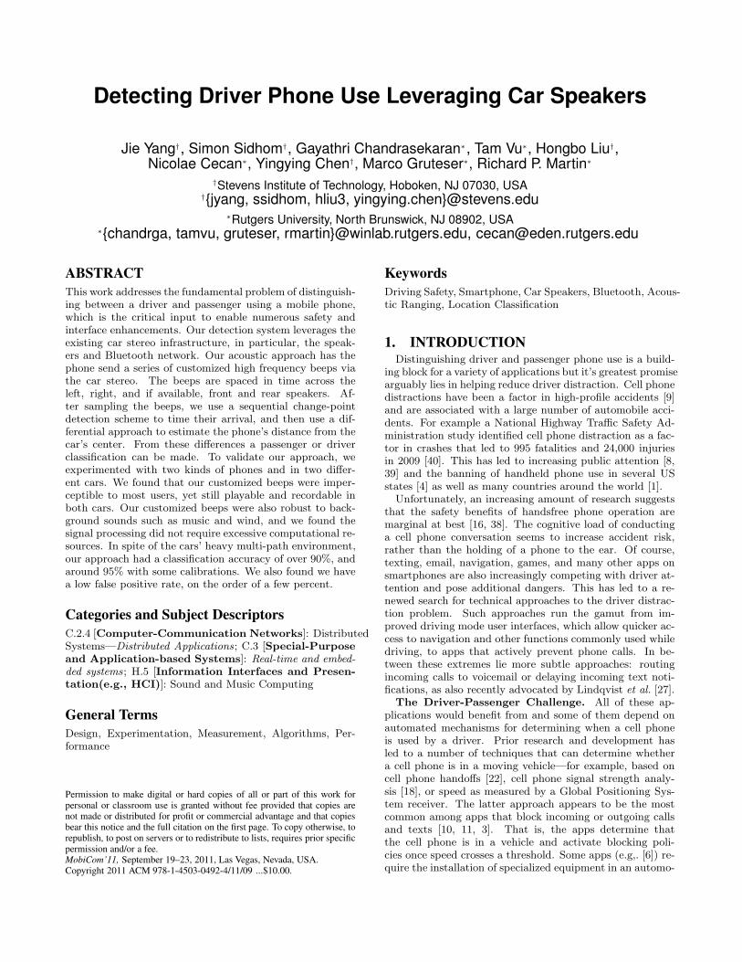
Figure 1: Illustration of the logical flow in our sys-tem.
Computational Feasibility on Smartphones. Standardsmartphone platforms should be able to execute thesignal processing and detection algorithms with sub-second runtimes.
3.2 Acoustic Ranging OverviewThe key idea underlying our driver phone use detection
system is to perform relative ranging with the car speakers.As illustrated in figure 1, the system, when triggered, say,by an incoming phone call, transmits an audio signal viaBluetooth to the car head unit. This signal is then playedthrough the car speakers. The phone records the emittedsound through its microphone and processes this recordedsignal to evaluate propagation delay. Rather than measur-ing absolute delay, which is affected by unknown processingdelays on the phone and in the head unit, the system mea-sures relative delay between the signal from the left and rightspeaker(s). This is similar in spirit to time-difference-of-arrival localization and does not require clock synchroniza-tion. Note, however, that the system does not necessarilyperform full localization.
In virtually all cars, the speakers are placed so that theplane equidistant to the left and right (front) speaker loca-tions separates the driver-side and passenger-side area. Thishas two benefits. First, for front seats (the most frequentlyoccupied seats), the system can distinguish driver seat andpassenger seat by measuring only the relative time differ-ence between the front speakers. Second, the system doesnot require any fingerprinting or calibration since a timedifference of zero always indicates that the phone is locatedbetween driver and passenger (on the center console). Forthese reasons, we refer to this approach as relative ranging.
This basic two-channel approach is practical with currenthandsfree and A2DP Bluetooth profiles which provide forstereo audio. The concept can be easily extended to four-channel, which promises better accuracy but would requireupdated surround sound head units and Bluetooth profiles.We will consider both the two and four channel optionsthroughout the remainder of the paper.
Our system differs from typical acoustic human speakerlocalization, in that we use a single microphone and multi-ple sound sources rather than a microphone array to detecta single sound source. This means that time differences onlyneed to be measured between signals arriving at the samemicrophone. This time difference can be estimated simplyby counting the number of audio samples between the twobeeps. Most modern smartphones offer an audio samplingfrequency of 44.1 kHz, which given the speed of sound theo-
Tij < 0 : Phone is
closer to speaker j
tij
Tij < 0 : Phone is
closer to speaker j
Tij = 0 : Phone is
equidistant from i and j
Tij > 0 : Phone is
closer to speaker i
Speaker i Speaker j
Propagation Delay
Tij = t’ij – tij
t’ij
t’ij
t’ij
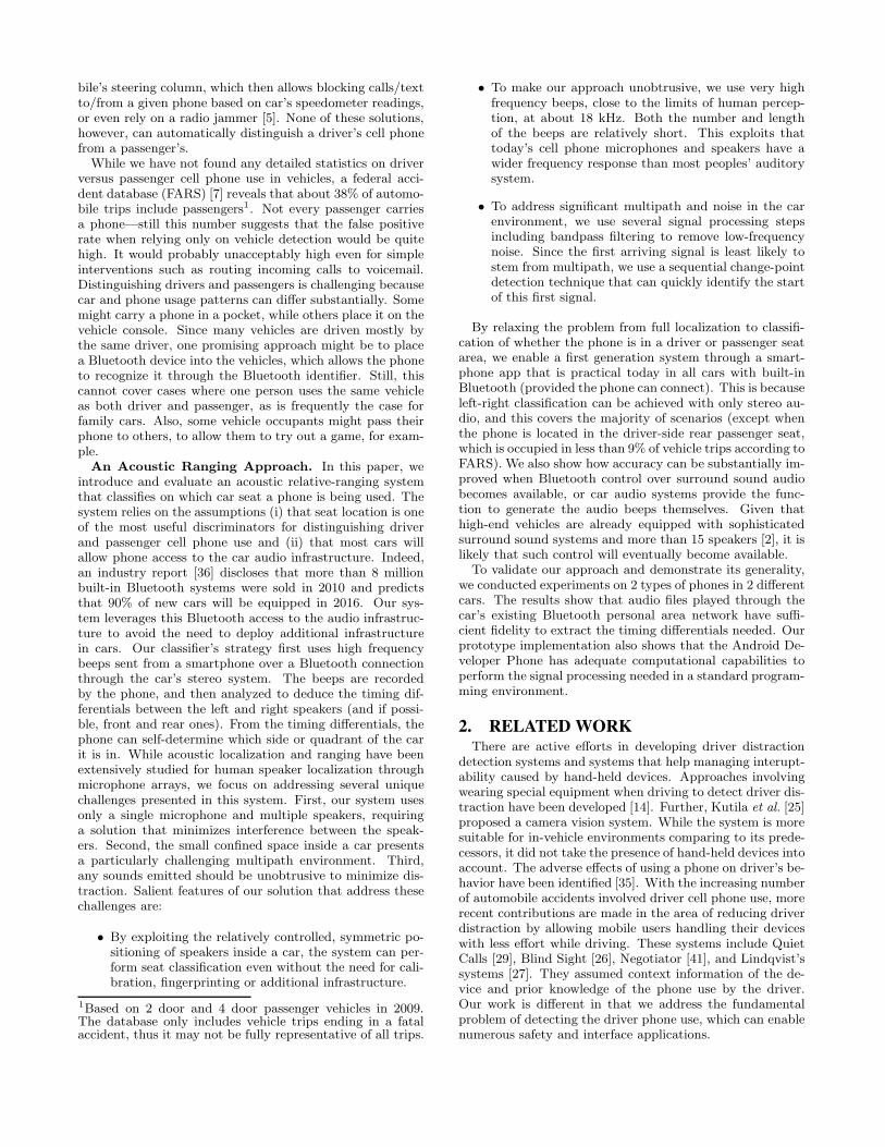
Figure 2: Relative ranging when applied to aspeaker pair i and j, for example front-left and front-right.
retically provides an accuracy of about 0.8 cm–the resolutionunder ideal situation, since the signal will be distorted .
Our multi-source approach also raises two new issues, how-ever. First, we have to ensure that the signals from differentspeakers do not interfere. Second, we need to be able todistinguish the signals emitted from the different speakers.We address both through a time-division multiplexing ap-proach. We let speakers emit sounds at different points intime, with a sufficiently large gap that no interference occursin the confined in-vehicle space. Since the order of speakersis known to the phone, it can also easily assign the receivedsounds to the respective speakers.
Figure 2 illustrates relative ranging approach for any twospeakers i and j, for example, front-left and front-right. As-sume the fixed time interval between two emitted soundsby a speaker pair i and j is ∆tij . Let ∆t′ij be the timedifference when the microphone records these sounds. Thetime difference of signal from ith and jth speaks arriving atphone is defined as
∆(Tji) = ∆t′ij − ∆tij , i 6= j i, j = 1, 2, 3, 4. (1)
Had the microphone been equidistant from these two speak-ers, we would have ∆(Tji) = 0. If ∆(Tji) < 0, the phone iscloser to the ith speaker and if ∆(Tji) > 0, it is closer to thejth speaker.
In our system, the absolute time the sounds emitted byspeakers are unknown to the phone, but the phone doesknow the time difference ∆tij . Similarly, the absolute timesthe phone records the sounds might be affected by phoneprocessing delays, but the difference ∆t′ij can be easily cal-culated using the sample counting. As can be seen, fromthe equations above, these two differences are sufficient todetermine which speaker is closer.
3.3 Beep Signal DesignIn designing the beep sound played through the car speak-
ers, we primarily consider two challenges: background noiseand unobtrusiveness.
Frequency Selection. We choose a high frequency beepat the edge of the phone microphone frequency responsecurve, since this makes it both easier to filter out noise andrenders the signal imperceptible for most, if not all, people.The majority of the typical car noise sources are in lowerfrequency bands. For example, the noise from the engine,tire/road, and wind are mainly located in the low frequencybands below 1 kHz [17], whereas conversation ranges fromapproximately 300 Hz to 3400 Hz [37]. Music has a wider
0 2 4 6 8 10 12 14 16 18 20
−20
0
20
40
60
80
SP
L (
dB
)
Frequency (kHz)(a) The absolute threshold of hearing (ATH) graph
0 2 4 6 8 10 12 14 16 18 20−60
−40
−20
0
Frequency (kHz)(b) Freuqency response of iPhone 3G and ADP2
Ma
gn
itu
de
(d
B)
iPhone 3G
ADP2
FrequencySensitivityGap
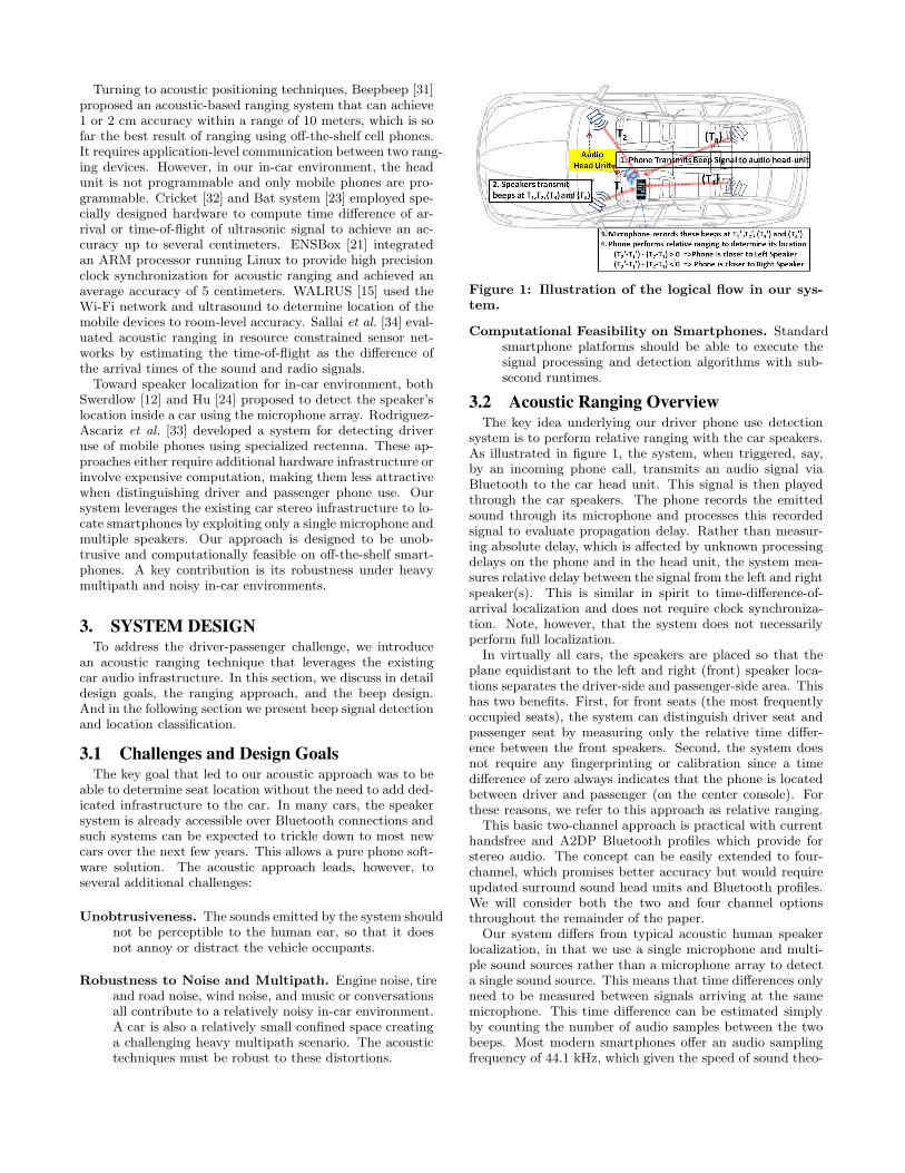
Figure 3: Frequency sensitivity comparison betweenthe human ear and smartphone.
range, the FM radio for example spans a frequency rangefrom 50 Hz to 15,000 Hz, which covers almost all naturallyoccurring sounds. Although separating noise can be difficultin the time domain, we enable straightforward separation inthe frequency domain by locating our signal above 15 kHz.
Such high-frequency sounds are also hard to perceive bythe human auditory system. Although the frequency rangeof human hearing is generally considered to be 20 Hz to 20kHz [20], high frequency sounds must be much louder tobe noticeable. This is characterized by the absolute thresh-old of hearing (ATH), which refers to the minimum soundpressure that can be perceived in a quiet environment. Fig-ure 3(a) shows how the ATH varies over frequency, as givenin [19]. Note, how the threshold of hearing increases sharplyfor frequencies over 10 kHz and how human hearing becomesextremely insensitive to frequencies beyond 18 kHz. For ex-ample, human ears can detect sounds as low as 0 dB soundpressure level (SPL) at 1 kHz, but require about 80 dB SPLbeyond 18 kHz—a 10,000 fold amplitude increase.
Fortunately, the current cell phone microphones are moresensitive to this high-frequency range. We experimentedwith an iPhone 3G and an Android Developer Phone 2(ADP2), and plotted their corresponding frequency responsecurves in Figure 3(b). Although the frequency response alsofalls off in the high frequency band it is still able to pickup sounds in a wider range than most human ears. Wetherefore choose frequencies in this high range. Since ourfrequency response experiments in Figure 3(b) show notice-able difference among phones beyond 18kHz, we chose boththe 16-18kHz range on the ADP2 phone and the 18-20kHzrange on the iPhone 3G for our experiments. Energy is uni-formly distributed over the entire range.
Length. The length of the beep impacts the overall de-tection time as well as the reliability of recording the beep.Too short a beep is not picked up by the microphone. Toolong a beep, will add delay to the system and will be moresusceptible to multi-path distortions. We found empiricallythat a beep length of 400 samples (i.e., 10 ms) represents agood tradeoff.
4. DETECTION ALGORITHMRealizing our approach requires four sub-tasks: Filtering,
Signal Detection, Relative Ranging and Location Classifica-

Location
Classification
Relative RangingCalculate dij
Input recorded sound
FilteringExtract signal energy at beep freq. band
Signal DetectionDetect the first arriving signal of beep
All the beeps detected?
N
Y
Two channel or four channel
stereo system?
Four channelsTwo channels
Left seats
( d13 + d24)/2>
Y
Y
N
NN Y
Driver’s seat Co-driver’s seat Back left seat Back right seat
Threshold?
d12>
Threshold? >
d34Threshold?
Y N
Right seats
d12>
Threshold?
Driver phone use Passenger
>
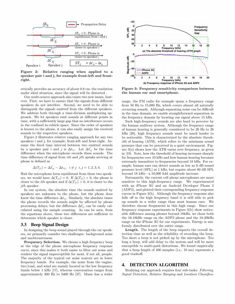
Figure 4: Flow of the detection algorithm.
tion. These correspond to the same parts the algorithmshown in Figure 4.
To classify the phone’s location, the specially designedbeeps, stored in files, are transmitted to the head-unit andplayed via the car’s speakers. Just before the beeps aretransmitted, the microphone is turned on and starts record-ing. The recorded sound is bandpass filtered around thefrequency band of the beep using a short-time Fourier trans-form (STFT) to remove most background noise. Next, asshown in Figure 4, a signal detection algorithm is applied.After each beep sound is detected, its start time is noted andrelative ranging is performed to obtain the time differencebetween the two speakers. Given a constant sampling fre-quency and known speed of sound, the corresponding phys-ical distance is easy to compute. Finally, location classifica-tion determines the position of the phone in car. We nextdescribe the two most important tasks, beep signal detectionand ranging and location classification, in detail.
4.1 Detecting Beep Arrival TimeDetecting the beep signal arrival under heavy multipath
in-car environments is challenging because the beeps canbe distorted due to interference from the multipath compo-nents. In particular, the commonly used correlation tech-nique, which detects the point of maximum correlation be-tween a received signal and a known transmitted signal, issusceptible to such distortions [31]. Furthermore, the use ofa high frequency beep signal can lead to distortions due tothe reduced microphone sensitivity in this range.
For these reasons, we adopt a different approach where wesimply detect the first strong signal in our frequency band.This is possible since there is relatively little noise and inter-ference from outside sources in our chosen frequency range.This is known as sequential change-point detection in sig-nal processing. The basic idea is to identify the first ar-riving signal that deviates from the noise after filtering outbackground noise [13]. Let {X1, ..., Xn} be a sequence ofrecorded audio signal by the mobile phone over n time point.Initially, without the beep, the observed signal comes fromnoise, which follows a distribution with density function p0.Later on, at an unknown time τ , the distribution changes
to density function p1 due to the transmission of beep sig-nal. Our objective is to identify this time τ , and to declarethe presence of a beep as quickly as possible to maintainthe shortest possible detection delay, which corresponds toranging accuracy.
To identify τ , we can formulate the problem as sequentialchange-point detection. In particular, at each time pointt, we want to know whether there is a beep signal presentand, if so, when the beep signal is present. Since the al-gorithm runs online, the beep may not yet have occurred.Thus, based on the observed sequence up to time point t{X1, ..., Xt}, we distinguish the following two hypothesesand identify τ :
H0 : Xi follows p0, i = 1, ..t,
H1 :
{
Xi follows p0, i = 1, .., τ − 1,
Xi follows p1, i = τ, ..., t.
If H0 is true, the algorithm repeats once more data samplesare available. If the observed signal sequence {X1, ..., Xt}includes one beep sound recorded by the microphone, theprocedure will reject H0 with the stopping time td, at whichthe presence of the beep signal is declared. A false alarm israised whenever the detection is declared before the changeoccurs, i.e., when td < τ . If td ≥ τ , then (td − τ ) is thedetection delay, which represents the ranging accuracy.
Sequential change-point detection requires that the sig-nal distribution for both noise and the beep is known. Thisis difficult because the distribution of the beep signal fre-quently changes due to multipath distortions. Thus, ratherthan trying to estimate this distribution, we use the cumula-tive sum of difference to the averaged noise level. This allowsfirst arriving signal detection without knowing the distribu-tion of the first arriving signal. Suppose the cell phone es-timates the mean value µ of noise starting at time t0 untilt1, which is the time that the phone starts transmitting thebeep. We want to detect the first arriving signal as the sig-nal that significantly deviates from the noise in the absenceof the distribution of the first arriving signal. Therefore, thelikelihood that the observed signal Xi is from the beep canbe approximated as
l(Xi) = (Xi − µ), (2)
given that the recorded beep signal is stronger than thenoise. The likelihood l(Xi) shows a negative drift if the ob-served signal Xi is smaller than the mean value of the noise,and a positive drift after the presence of the beep, i.e., Xi
stronger than the noise. The stopping time for detecting thepresence of the beep is given by
td = inf(k|sk ≥ h), satisfy sm ≥ h, m = k, .., k + W, (3)
where h is the threshold, W is the robust window used toreduce the false alarm, and sk is the metric for the observedsignal sequence {X1, ..., Xk}, which can be calculated recur-sively:
sk = max{sk−1 + l(Xk), 0}, (4)
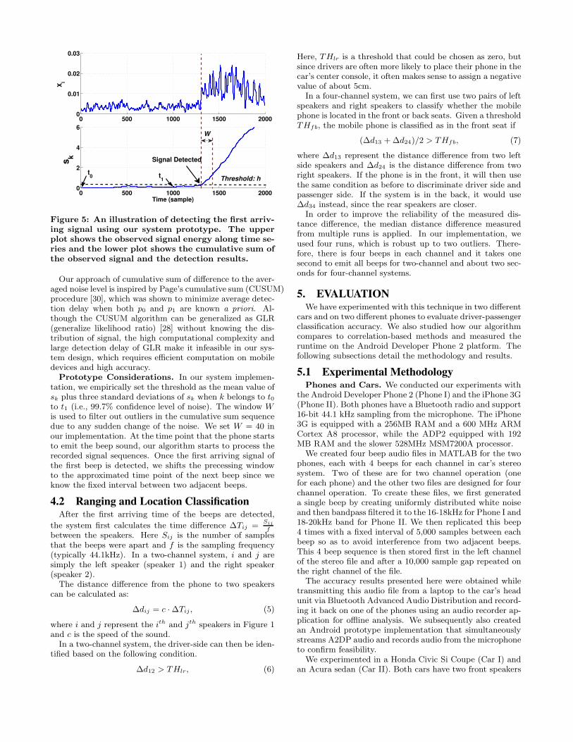
with s0 = 0.Figure 5 shows an illustration of the first arriving signal
detection by using our system prototype. The upper plotshows the observed signal energy along time series and thelower plot shows the cumulated sum of the observed signal.
0 500 1000 1500 20000
0.01
0.02
0.03X
i
0 500 1000 1500 20000
2
4
6
Time (sample)
sk
W
Signal Detected
t0
t1 Threshold: h
Figure 5: An illustration of detecting the first arriv-ing signal using our system prototype. The upperplot shows the observed signal energy along time se-ries and the lower plot shows the cumulative sum ofthe observed signal and the detection results.
Our approach of cumulative sum of difference to the aver-aged noise level is inspired by Page’s cumulative sum (CUSUM)procedure [30], which was shown to minimize average detec-tion delay when both p0 and p1 are known a priori. Al-though the CUSUM algorithm can be generalized as GLR(generalize likelihood ratio) [28] without knowing the dis-tribution of signal, the high computational complexity andlarge detection delay of GLR make it infeasible in our sys-tem design, which requires efficient computation on mobiledevices and high accuracy.
Prototype Considerations. In our system implemen-tation, we empirically set the threshold as the mean value ofsk plus three standard deviations of sk when k belongs to t0to t1 (i.e., 99.7% confidence level of noise). The window Wis used to filter out outliers in the cumulative sum sequencedue to any sudden change of the noise. We set W = 40 inour implementation. At the time point that the phone startsto emit the beep sound, our algorithm starts to process therecorded signal sequences. Once the first arriving signal ofthe first beep is detected, we shifts the precessing windowto the approximated time point of the next beep since weknow the fixed interval between two adjacent beeps.
4.2 Ranging and Location ClassificationAfter the first arriving time of the beeps are detected,
the system first calculates the time difference ∆Tij =Sij
f
between the speakers. Here Sij is the number of samplesthat the beeps were apart and f is the sampling frequency(typically 44.1kHz). In a two-channel system, i and j aresimply the left speaker (speaker 1) and the right speaker(speaker 2).
The distance difference from the phone to two speakerscan be calculated as:
∆dij = c · ∆Tij , (5)
where i and j represent the ith and jth speakers in Figure 1and c is the speed of the sound.
In a two-channel system, the driver-side can then be iden-tified based on the following condition.
∆d12 > THlr, (6)
Here, THlr is a threshold that could be chosen as zero, butsince drivers are often more likely to place their phone in thecar’s center console, it often makes sense to assign a negativevalue of about 5cm.
In a four-channel system, we can first use two pairs of leftspeakers and right speakers to classify whether the mobilephone is located in the front or back seats. Given a thresholdTHfb, the mobile phone is classified as in the front seat if
(∆d13 + ∆d24)/2 > THfb, (7)
where ∆d13 represent the distance difference from two leftside speakers and ∆d24 is the distance difference from tworight speakers. If the phone is in the front, it will then usethe same condition as before to discriminate driver side andpassenger side. If the system is in the back, it would use∆d34 instead, since the rear speakers are closer.
In order to improve the reliability of the measured dis-tance difference, the median distance difference measuredfrom multiple runs is applied. In our implementation, weused four runs, which is robust up to two outliers. There-fore, there is four beeps in each channel and it takes onesecond to emit all beeps for two-channel and about two sec-onds for four-channel systems.
5. EVALUATIONWe have experimented with this technique in two different
cars and on two different phones to evaluate driver-passengerclassification accuracy. We also studied how our algorithmcompares to correlation-based methods and measured theruntime on the Android Developer Phone 2 platform. Thefollowing subsections detail the methodology and results.
5.1 Experimental MethodologyPhones and Cars. We conducted our experiments with
the Android Developer Phone 2 (Phone I) and the iPhone 3G(Phone II). Both phones have a Bluetooth radio and support16-bit 44.1 kHz sampling from the microphone. The iPhone3G is equipped with a 256MB RAM and a 600 MHz ARMCortex A8 processor, while the ADP2 equipped with 192MB RAM and the slower 528MHz MSM7200A processor.
We created four beep audio files in MATLAB for the twophones, each with 4 beeps for each channel in car’s stereosystem. Two of these are for two channel operation (onefor each phone) and the other two files are designed for fourchannel operation. To create these files, we first generateda single beep by creating uniformly distributed white noiseand then bandpass filtered it to the 16-18kHz for Phone I and18-20kHz band for Phone II. We then replicated this beep4 times with a fixed interval of 5,000 samples between eachbeep so as to avoid interference from two adjacent beeps.This 4 beep sequence is then stored first in the left channelof the stereo file and after a 10,000 sample gap repeated onthe right channel of the file.
The accuracy results presented here were obtained whiletransmitting this audio file from a laptop to the car’s headunit via Bluetooth Advanced Audio Distribution and record-ing it back on one of the phones using an audio recorder ap-plication for offline analysis. We subsequently also createdan Android prototype implementation that simultaneouslystreams A2DP audio and records audio from the microphoneto confirm feasibility.
We experimented in a Honda Civic Si Coupe (Car I) andan Acura sedan (Car II). Both cars have two front speakers

D r i v e r ’ sC o n t r o lA r e aFigure 6: Illustration of testing positions in Phone I
Car I scenario and driver’s control area.
located at two front doors’ lower front sides, and two rearspeakers in the rear deck. The interior dimensions of CarI are about 175cm (width) by 183cm (length) and about185cm by 203cm for Car II.
Since both cars are equipped with the two-channel stereosystem, the four channel sound system is simulated by usingthe headunit’s fader system. Specifically, we encode a twochannel beep sound and play the two channel beep soundfirst at two front speakers while muting the rear speakers, wethen play the two channel beep sound at two rear speakerswhile muting the front speakers.
Experimental Scenarios. We conducted experimentswhere we placed a phone in various positions that we believeare commonly used. We also varied the number of passen-gers and the amount and type of background noise. Due tosafety reasons (experiments require manual intervention andchanging phone positions can be difficult), we restricted thenumber of experiments while driving and conducted moreexhaustive testing in a stationary setting.
We organized our experiments in three representative sce-narios:
Phone I, Car I : This set of experiments uses the AndroidDeveloper Phone 2 in the Honda Civic while stationary.Background noises stem from conversation and an idling en-gine. As illustrated in Figure 6, we placed the phone in ninedifferent locations: Driver’s left pant pocket (A), driver’sright pant pocket (B), a cupholder on the center console(C), front passenger’s left pant pocket (D), front passenger’sright pant pocket (E), left rear passenger’s left pocket, leftrear passenger’s right pocket (G), right rear passenger’s leftpocket (H) and right rear passengers right pocket (I). Whenthe phone was in the 5 front positions, there are two cases:(1) only driver and front passenger were in the car; and (2)driver, front passenger, and left rear passenger were in thecar. When the phone was located in the rear positions, theadditional rear passenger always occupied the car.
Phone II, Car II : These experiments deploy the iPhone3G in the Acura, again stationary but this time withoutbackground noise. We use three occupancy variants: onlydriver is in the car; driver and co-driver are in the car; driver,co-driver and one passenger are in the car. (1) There are twopositions tested in the first case: driver door’s handle andcup holder; (2) four positions in the second case: the sametwo positions as before, plus co-driver’s left pant pocket andco-driver door’s handle; and (3) six positions in the thirdcase: all four positions from the second case, plus passen-ger holding the phone at rear left seat and rear left door’shandle.
Highway Driving : ADP2 is deployed in Car I. The car
Scenario Threshold DR FPR Accuracy
Two-channel stereo system, phone at front seatsHighway Un-calibrated 99% 4% 97.5%
Calibrated 100% 4% 98%Phone I, Car I Un-calibrated 94% 3% 95%
Calibrated 98% 7% 96%Phone II, Car II Un-calibrated 95% 24% 87%
Calibrated 91% 5% 92%
Four-channel stereo system, phone at all seatsPhone I, Car I Un-calibrated 94% 3% 95%
Calibrated 94% 2% 96%Phone II, Car II Un-calibrated 84% 16% 84%
Calibrated 91% 3% 94%
Table 1: Detection rate (DR), false positive rate(FPR) and accuracy when determining the driverphone use under various scenarios.
is driving on highway at the speed of 60MPH with musicplaying in the car. The four positions tested are: driver’sleft pant pocket, cup holder, co-driver holding the phone,and co-driver’s right pant pocket. We also repeat this set ofexperiments with both front windows open, as a worst casebackground noise scenario.
Metrics. One of our key evaluation questions is howaccurately our technique distinguishes phones that likely areused by the driver from phones likely used by passengers.In this evaluation, we consider all phones in positions thatare within easy reach of the driver as phones used by thedriver. This includes the driver’s left and right pockets, thedriver door’s handle, and the cup holder. We have markedthis as the driver’s control area in Fig. 6. We consider allother positions passenger phone positions. To evaluate theperformance of our system, we therefore define the followingmetrics:
Classification Accuracy (Accuracy). Classification accu-racy is defined as the percentage of the trials that were cor-rectly classified as driver phone use or correctly classified aspassenger phone use.
Detection Rate (DR), False Positive Rate (FPR). Detec-tion rate is defined as the percentage of trials within thedriver control area that are classified as driver phone use.False positive rate is defined as the percentage of passengerphone use that are classified as driver phone use.
Measurement Error. Measurement error is defined as thedifference between the measured distance difference (i.e.,∆dij) and the true distance difference. This metric directlyevaluates the performance of relative ranging in our algo-rithm.
5.2 Classification of Driver Phone Use
5.2.1 Driver vs. Passenger Phone Use
Table 1 shows the detection rate, false positive rate andaccuracy when determining driver phone use using the twochannel stereo system. Note that since the 2-channel sys-tem cannot distinguish the driver-side passenger seat fromthe driver seat, we have only tested front phone positionsfor this experiment. To test the robustness of our systemto different types of cars, we distinguish between the Un-calibrated system, which uses a default threshold, and theCalibrated system, wherein the threshold is determined bytaking into the consideration of car’s dimensions and speakerlayout.
We set the Un-calibrated default threshold THlr = −5cmfor both Car I and Car II. We shift the THlr from 0cm to

-5cm, because we define the cup holder position within thedriver’s control area. Recall, that the cup holder is equidis-tant from both speakers and results in distance differencenear zero. For Calibrated threshold, it is THlr = −7cm andTHlr = −2cm in Car I and Car II settings respectively.
Two-channel stereo system. From Table 1, the impor-tant observation in the Highway scenario is that our systemcan achieve close to 100% detection rate (with a 4% falsepositive rate), which results in about 98% accuracy, suggest-ing our system is highly effective in detecting driver phoneuse while driving. The detection rate for both Un-calibratedand Calibrated is more than 90% while the false positiverate is around 5% except for Car II setting. This indicatesthe effectiveness of our detection algorithm. The high falsepositive rate of Car II setting can be reduced through cal-ibration of the threshold. Although the detection rate isreduced when reducing the false positive rate for Car II, theoverall detection accuracy is improved. These results showthat our system is robust to different types of cars and canprovide reasonable accuracy without calibration (althoughcalibration still helps).
Recall that in this experiment we only considered frontphone positions since the two-channel stereo system canonly distinguish between driver-side and passenger-side po-sitions. With phone positions on the back seats, particularlythe driver-side rear passenger seat, the detection accuracywill be degraded, although the detection rate remains thesame. Real life accuracy will depend on where drivers placetheir phones in the car and how often passengers use theirphone from other seats. Unfortunately, we were unable togather this information. We did however find informationon passenger seat occupancy in the FARS 2009 database [7].Encouragingly it shows that the two front seats are the mostfrequently occupied seats. In particular, according to FARS2009 database, 83.5% of vehicles are only occupied by driverand possibly one front passenger, whereas only about 16.5%of trips occur with back seat passengers. More specifically,only 8.7% of the trips include a passenger sitting behinddriver seat–the situation that would increase our false posi-tive rate.
If we weigh the phone locations by these probabilities, thefalse positive rate only increases to about 20% even withthe two channel system. The overall accuracy of detectingdriver phone use remains at about 90% for all three experi-mental scenarios in our system. This is very encouraging asit indicates our system can successfully produce high detec-tion accuracy even with the systems limited to two-channelstereo in today’s cars.
Four-channel stereo system. We now consider thefour-channel system to study how accuracy could be im-proved when surround sound is available. The results of us-ing four-channel system under both Un-calibrated and Cal-ibrated thresholds is shown in Tables 1. The un-calibratedthresholds are THfb = 0cm and THlr = −5cm for both CarI and Car II. The calibrated thresholds are THfb = 15cmand THlr = −5cm for Car I, whereas they are THfb =−24cm and THlr = −2cm for Car II. We found that withthe calibrated thresholds, the detection rate is above 90%and the accuracy is around 95% for both settings. Thisshows that the four-channel system can improve the de-tection performance, compared to that of the two-channelstereo system. In addition, the performance under un-calibratedthresholds is similar to that under calibrated thresholds for
A B C D E F G H I0
0.2
0.4
0.6
0.8
1
Position
Ac
cu
rac
y
Figure 7: Accuracy of detecting driver phone use ateach position in Car I (i.e., positions plotted in Fig-ure 6) under calibrated thresholds with four-channelstereo system.
Car I setting, however, it is much worse than that of cali-brated thresholds for Car II settings. This suggests that cal-ibration is more important for distinguishing the rear area,because the seat locations vary more in the front-back di-mension across cars (and due to manual seat adjustment).
5.2.2 Position Accuracy and Seat Classification
We next evaluate our algorithm accuracy at different po-sitions and seats within the car. Figure 7 shows the ac-curacy of detecting driver phone use for different positionsin Car I setting under calibrated thresholds. We observedthat we can correctly classify all the trials at the positionsA,B,E,G,H,I as denoted in Figure 6, whereas the detectionaccuracy decreases to 93% for position D (i.e., co-driver’s leftpocket) and 82% for position C (i.e., cup holder). Addition-ally, we tested doors’ handle positions in Car II setting andfound the accuracy for driver’s door handle is 99%, and 97%for co-driver’s door handle. These results provide a betterunderstanding of our algorithm’s performance at differentpositions in car.
We further derive seat classification results. Table 2 showsthe accuracy when determining the phone at each seat un-der Un-calibrated and Calibrated thresholds using the four-channel stereo system. We found that the accuracy of theback seats is much higher than that of front seats. Becausethere is a cup holder position tested in the front. It is hardto classify the cup holder and co-driver’s left position sincethey are physically close to each other.
5.2.3 Left vs. Right Classification
Figure 8 illustrates the boxplot of the measured ∆d12 atdifferent tested positions. On each box, the central markis the median, the edges of the box are the 25th and 75thpercentiles, the whiskers extend to the most extreme data
Driver Co-driver Rear Left Rear Right
Phone I, Car IUn-calibrated 95% 95% 99% 99%Calibrated 96% 95% 99% 99%Phone II, Car IIUn-calibrated 84% 88% 94% N/ACalibrated 94% 94% 98% N/A
Table 2: Accuracy of determining the phone at eachseat with four-channel stereo system.

Driver−Right Driver−Left Cup−Holder Co−driver−LCo−driver−R
−120
−80
−40
0
40
80
Re
lati
ve
Ra
ng
ing
(c
m)
(a) Boxplot: Phone I, Car I
Driver Door Cup Holder Co−driver LeftCo−driver Door−20
−10
0
10
20
30
Re
lati
ve
Ra
ng
ing
(c
m)
(b) Boxplot: Phone II, Car II
Figure 8: Boxplot of the measured ∆d12 for all frontpositions in two-channel stereo system.
points. We note that the scale of y-axis in Figure 8 (a) is dif-ferent from that in Figure 8 (b). We found that these boxesare clearly separated from each other showing that we ob-tained different relative ranging values at different positions.And these positions can be perfectly identified by examiningthe measured values from relative ranging except Cup holderand Co-driver’s left positions for both Car I and Car II set-tings. By comparing Figure 8 (a) and (b), we found thatthe relative ranging results of driver’s and co-driver’s doorsare much smaller than that of driver’s left and co-driver’sright pockets, which is conflict with the groundtruth. Thisis mainly because the shortest path that the signal travelsto reach the phone is significantly longer than the actualdistance between the phone and the nearby speaker whenputting the phone at door’s handle since there is no directpath between the phone and speaker, i.e., the nearby speakeris facing the opposite side of the phone.
To compare the stability of our ranging results under theHighway driving scenario to the stationary one, we plottedthe standard deviation of relative ranging results at differentpositions in Figure 9. We observed the encouraging resultsthat our algorithm produces the similar stability of detectionwhen car is driving on highway to that when car is parked.We note that at the co-driver’s right position (i.e., Co-driver-R), the relative ranging results of Highway driving scenariostill achieves 7cm of standard deviation, although it is not asstable as that of Phone I Car I setting due to the movementof the co-driver’s body caused by moving car.
5.2.4 Front vs. Back Classification
In front and back classification, the detection rate is de-fined as the percentage of the trials on front seats that areclassified as front seats. False positive rate is defined as
Driver−Right Cup−Holder Co−driver−Rright0
2
4
6
8
10
Std
. o
f re
lati
ve
ra
ng
ing
(c
m)
Phone I Car I
Highway
Figure 9: Stability study of relative ranging betweenhighway driving and stationary scenarios.
0 0.01 0.02 0.03 0.04 0.05 0.06 0.07
0.88
0.9
0.92
0.94
0.96
0.98
1
False Positive Rate
Dete
cti
on
Rate
51
37
29
15 5 4 3 1 04.5
Figure 10: ROC curve of detecting the phone atfront seats for Phone I, Car I scenario.
the percentage of back seat trials that are classified as frontseats. Figure 10 plotted Receiver Operating Curve (ROC)of detecting the phone at front seats in Car I setting. Wefound that our system achieved over 98% detection rate withless than 2% false positive rate. These results demonstratethat it is relatively easier to classify front and back seatsthan that of left and right seats since the distance betweenthe front and back seats is relatively larger. Our algorithmcan perfectly classify front seats and back seats with only afew exceptions.
5.3 Results of Relative RangingWe next present the measurement error of our relative
ranging mechanism and compare it to the previous workusing chirp signal and correlation signal detection methodwith multipath mitigation mechanism, which achieved highaccuracy for acoustic ranging using off-the-shelf mobile de-vices [31].
Correlation-Based Method. To be resistant to am-bient noise, the correlation method uses the chirp signal asbeep sound. To perform signal detection, this method corre-lates the chirp sound with the recorded signal using L2-normcross-correlation, and picks the time point when the corre-lation value is the maximum as the time signal detected. Tomitigate the multipath, instead of using the maximum corre-lation value, the earliest sharp peak in the correlation valuesis suggested as the signal detected time [31]. We refer thisapproach as correlation method with mitigation mechanism.
Strategy for Comparison. To investigate the effectof multipath in an enclosed in-car environment and the re-sistance of beep signals to background noise, we designedexperiments by putting ADP2 in car I at three different po-sitions with line-of-sight (LoS) to two front speakers. At
0 2 4 6 8 10 120
0.2
0.4
0.6
0.8
1
Measurement Error (cm)
Pe
rce
nta
ge
0 0.5 1 1.50
0.2
0.4
(a) Our method
0 2 4 6 8 10 120
0.2
0.4
0.6
0.8
1
Measurement Error (cm)
Pe
rce
nta
ge
(b) Correlation method
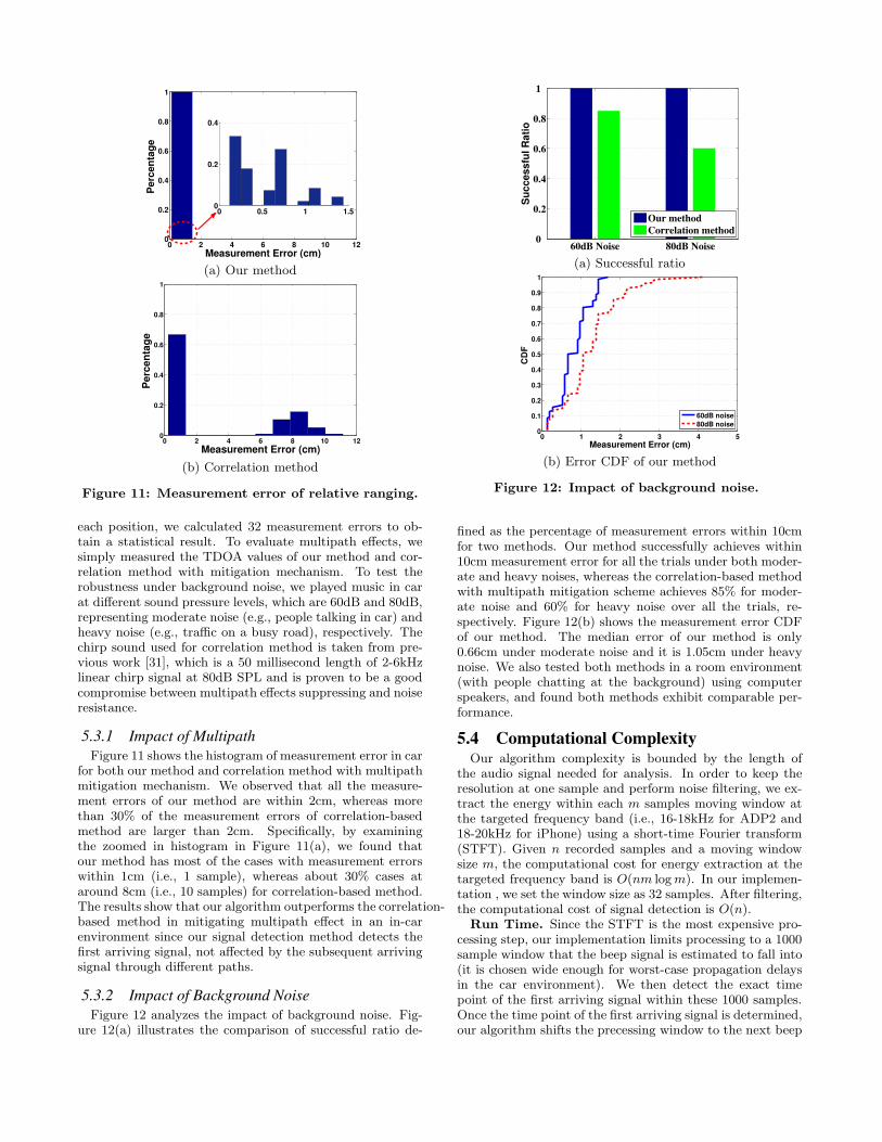
Figure 11: Measurement error of relative ranging.
each position, we calculated 32 measurement errors to ob-tain a statistical result. To evaluate multipath effects, wesimply measured the TDOA values of our method and cor-relation method with mitigation mechanism. To test therobustness under background noise, we played music in carat different sound pressure levels, which are 60dB and 80dB,representing moderate noise (e.g., people talking in car) andheavy noise (e.g., traffic on a busy road), respectively. Thechirp sound used for correlation method is taken from pre-vious work [31], which is a 50 millisecond length of 2-6kHzlinear chirp signal at 80dB SPL and is proven to be a goodcompromise between multipath effects suppressing and noiseresistance.
5.3.1 Impact of Multipath
Figure 11 shows the histogram of measurement error in carfor both our method and correlation method with multipathmitigation mechanism. We observed that all the measure-ment errors of our method are within 2cm, whereas morethan 30% of the measurement errors of correlation-basedmethod are larger than 2cm. Specifically, by examiningthe zoomed in histogram in Figure 11(a), we found thatour method has most of the cases with measurement errorswithin 1cm (i.e., 1 sample), whereas about 30% cases ataround 8cm (i.e., 10 samples) for correlation-based method.The results show that our algorithm outperforms the correlation-based method in mitigating multipath effect in an in-carenvironment since our signal detection method detects thefirst arriving signal, not affected by the subsequent arrivingsignal through different paths.
5.3.2 Impact of Background Noise
Figure 12 analyzes the impact of background noise. Fig-ure 12(a) illustrates the comparison of successful ratio de-
60dB Noise 80dB Noise0
0.2
0.4
0.6
0.8
1
Su
ccessfu
l R
ati
o
Our method
Correlation method
(a) Successful ratio
0 1 2 3 4 50
0.1
0.2
0.3
0.4
0.5
0.6
0.7
0.8
0.9
1
Measurement Error (cm)
CD
F
60dB noise
80dB noise
(b) Error CDF of our method
Figure 12: Impact of background noise.
fined as the percentage of measurement errors within 10cmfor two methods. Our method successfully achieves within10cm measurement error for all the trials under both moder-ate and heavy noises, whereas the correlation-based methodwith multipath mitigation scheme achieves 85% for moder-ate noise and 60% for heavy noise over all the trials, re-spectively. Figure 12(b) shows the measurement error CDFof our method. The median error of our method is only0.66cm under moderate noise and it is 1.05cm under heavynoise. We also tested both methods in a room environment(with people chatting at the background) using computerspeakers, and found both methods exhibit comparable per-formance.
5.4 Computational ComplexityOur algorithm complexity is bounded by the length of
the audio signal needed for analysis. In order to keep theresolution at one sample and perform noise filtering, we ex-tract the energy within each m samples moving window atthe targeted frequency band (i.e., 16-18kHz for ADP2 and18-20kHz for iPhone) using a short-time Fourier transform(STFT). Given n recorded samples and a moving windowsize m, the computational cost for energy extraction at thetargeted frequency band is O(nm log m). In our implemen-tation , we set the window size as 32 samples. After filtering,the computational cost of signal detection is O(n).
Run Time. Since the STFT is the most expensive pro-cessing step, our implementation limits processing to a 1000sample window that the beep signal is estimated to fall into(it is chosen wide enough for worst-case propagation delaysin the car environment). We then detect the exact timepoint of the first arriving signal within these 1000 samples.Once the time point of the first arriving signal is determined,our algorithm shifts the precessing window to the next beep
sound since we know the fixed interval between two adja-cent beeps. Thus, the computational time for one beep isapproximately equivalent to process 1000 samples. We im-plemented this step on the ADP2 with JTransforms libraryfor STFT and measured the average processing time of ourdetection algorithm as about 0.5 second for the two-channelsystem and about 1 second for the four-channel system.The windowing implementation has significantly reduced theprocessing time of our algorithm and further optimizationsare likely possible.
6. DISCUSSIONBluetooth issues. We have assumed that a Bluetooth
connection is already established. We believe that this isa reasonable assumption for people who (usually) drive agiven car. People are likely to pair their phone with the in-car Bluetooth system and after the first pairing, connectionsare usually automatically established when the phone comesin range of the car. It is not common practice, however, foroccasional passengers who are never drivers. There seem tobe several possible approaches to address this issue: (i) hav-ing phones listen for beeps transmitted by other phones atregular known times, (ii) standardizing a Bluetooth profilefor such beep transmission which allows auto-pairing, (iii)building the beep transmissions into car audio systems, sothat phones only need to listen. The Bluetooth connectioncould also be in use for playing music using the A2DP pro-file. In this case, the phone should be able to insert thebeeps into the music stream.
Limitations. Even with access to four audio channels,the system might not accurately distinguish driver and pas-senger for several reasons. First, if the phone is placed un-der a heavy winter coat or inside a full bag, the beep soundsmight be too muffled to be accurately detected. Second, ifthe driver places the phone on an empty passenger seat, thesystem might correctly detect the seat, but an incoming callcould still distract the driver. Still, we believe the accuracyof this system will be a significant improvement over currentsystems that only seek to determine whether the phone isused inside a vehicle. We have also left buses, trains, andother vehicles outside the scope of this work—phones couldidentify such vehicles by comparing GPS traces with knownroutes. In these vehicles it is also more cost-efficient to add adevice to the driver cabin. A more fundamental limitation isthe probabilistic nature of our approach. We can not placehard boundaries on accuracy because of many environmentalunknowns, some of which are described above. This meansthat our approach is less suitable for applications dependingon perfect accuracy. Rather, they will serve to enhance theuser experience and nudge drivers towards safer behavior.Finally, Finally, this system is not intended for continuouslytracking phone position, since its energy consumption wouldbe quite substantial. Rather, we envision that this techniquewould be sporadically triggered, for example, by an incom-ing phone call or when entering the vehicle (upon Bluetoothconnect).
Applications. In this paper, we have concentrated onlyon distinguishing drivers and passengers, a complete systemshould also include cellphone-based speed detection tech-niques to determine whether the car is driving. As alludedto in the introduction, there are several applications of thisdriver phone use detection system: (i) it could automaticallybring up less distracting driver user interfaces; (ii) the beeps
might only be transmitted when a call or text is coming in,to determine whether the phone should ring or whether thecall should go to voicemail; (iii) the ’driving’ status might bedisplayed in friends dialer applications to discourage themfrom calling. Integration with vehicle controls, is anotherdimension that could be explored. Perhaps a driver chat-ting on the phone should increase the responsiveness of avehicle’s braking system, since this driver is more likely tobreak late. It could also affect the level of intrusiveness oflane-departure warning and other driver assist systems. Fi-nally, the information could be used to lock the phone toprevent the driver from calling—we note, however, that thesystem is not secure against a user intentionally trying tofool it. Thus, it is less suitable for such enforcement actions.
7. CONCLUSIONSWe developed a driver mobile phone use detection sys-
tem that requires only software changes on smartphones. Itachieves this by leveraging the existing infrastructure of carspeakers for ranging via Bluetooth. The proposed systemdetects driver phone use by estimating the range betweenthe phone and car’s speakers. To estimate range, we devel-oped an acoustic based relative ranging technique in whichthe phone plays and records a specially designed acoustic sig-nal through car’s speakers. Our specially designed acousticsignal is unobtrusive as well as robust to background noisewhen driving. Our algorithm achieves high accuracy un-der heavy multipath in-car environments by using sequentialchange-point detection to identify the first arriving signal.
We further demonstrated the viability of distinguishingbetween driver’s and passenger’s phone use working withinthe confines of the existing handsfree audio infrastructure.Our prototype showed the generality of our approach, as weapplied it to two different phone types and two different carsunder various scenarios. Our system can achieve over 90%of detection rates as well as accuracy, with low false positiverate.
8. ACKNOWLEDGMENTSWe thank the anonymous reviewers for comments that im-
proved this paper. This work is supported in part by theNational Science Foundation Grants CNS-0954020, CNS-1016303, CNS-1040735 and CNS-0845896.
9. REFERENCES[1] http://tinyurl.com/an5yl.
[2] http://www.bang-olufsen.com/sound-system-audi-r8.
[3] Drivesmart plus. http://tinyurl.com/4v7oygy.
[4] Governors highway safety association.http://tinyurl.com/39hfe7.
[5] Guardian angel vehicle platform.http://www.trinitynoble.com/.
[6] Key2safedriving app.http://www.key2safedriving.com/.
[7] National highway traffic safety administration:Fatality analysis reporting system.http://tinyurl.com/24h2t7.
[8] The new york times. http://tinyurl.com/4etjlja.
[9] Reuters. http://tinyurl.com/4uoxefh.
[10] Textecution. http://www.textecution.com/.
[11] txtblocker. http://www.txtblocker.com/.
[12] B. K. Alexej Swerdlow, Timo Machmer andK. Kroschel. Speaker position estimation in vehiclesby means of acoustic analysis. In 34th DeutscheJahrestagung fur Akustik (DAGA ’07), Stuttgart,Germany, 2007. SpringerVerlag.
[13] M. Basseville and I. Nikiforov. Detection of abruptchanges: theory and application, volume 10. PrenticeHall, 1993.
[14] L. Bergasa, J. Nuevo, M. Sotelo, R. Barea, andM. Lopez. Real-time system for monitoring drivervigilance. IEEE Transactions on IntelligentTransportation Systems, 7(1):63 –77, 2006.
[15] G. Borriello, A. Liu, T. Offer, C. Palistrant, andR. Sharp. Walrus: wireless acoustic location withroom-level resolution using ultrasound. In Proceedingsof the 3rd international Conference on MobileSystems, Applications, and Services (MobiSys ’05),pages 191–203, New York, NY, 2005.
[16] J. Caird, C. Willness, P. Steel, and C. Scialfa. Ameta-analysis of the effects of cell phones on driverperformance. Accident Analysis & Prevention,40(4):1282–1293, 2008.
[17] G. Cerrato. Automotive Sound Quality–Powertrain,Road and Wind Noise. Sound & vibration, pages16–24, 2009.
[18] G. Chandrasekaran, T. Vu, A. Varshavsky,M. Gruteser, R. P. Martin, J. Yang, and Y. Chen.Tracking vehicular speed variations by warping mobilephone signal strengths. In Proceedings of InternationalConference on Pervasive Computing andCommunication (PerCom ’11), Seattle, WA, 2011.
[19] H. Fastl and E. Zwicker. Psychoacoustics: facts andmodels. Springer-Verlag New York Inc, 2007.
[20] S. Gelfand and H. Levitt. Hearing: An introduction topsychological and physiological acoustics, volume 2.Marcel Dekker New York, 2004.
[21] L. Girod, M. Lukac, V. Trifa, and D. Estrin. Thedesign and implementation of a self-calibratingdistributed acoustic sensing platform. In Proceedingsof the 4th international conference on Embeddednetworked sensor systems (Sensys ’06), pages 71–84.ACM, 2006.
[22] D. Gundlegard and J. Karlsson. Handover locationaccuracy for travel time estimation in gsm and umts.In IEEE Intelligent Transportation SystemsConference (ITSC ’09), March 2009.
[23] A. Harter, A. Hopper, P. Steggles, A. Ward, andP. Webster. The anatomy of a context-awareapplication. In Proceedings of the 5th annualACM/IEEE international conference on Mobilecomputing and networking (Mobicom ’99), pages59–68, 1999.
[24] J. Hu, C. Cheng, and W. Liu. A robuststatistical-based speaker’s location detection algorithmin a vehicular environment. EURASIP Journal onApplied Signal Processing, 2007(1):181, 2007.
[25] M. Kutila, M. Jokela, G. Markkula, and M. Rue.Driver distraction detection with a camera visionsystem. In IEEE International Conference on ImageProcessing (ICIP ’07), 16 2007.
[26] K. A. Li, P. Baudisch, and K. Hinckley. Blindsight:eyes-free access to mobile phones. In Proceeding of thetwenty-sixth annual SIGCHI conference on Humanfactors in computing systems (CHI ’08), CHI ’08,pages 1389–1398, New York, NY, 2008.
[27] J. Lindqvist and J. Hong. Undistracted driving: Amobile phone that doesn’t distract. In 12th Workshopon Mobile Computing Systems and Applications(HotMobile ’11), 2011.
[28] G. Moustakides. Optimal procedures for detectingchanges in distributions. Annals of Statistics,14(1379-1387), 1986.
[29] L. Nelson, S. Bly, and T. Sokoler. Quiet calls: talkingsilently on mobile phones. In Proceedings of theSIGCHI conference on Human factors in computingsystems (CHI’01), pages 174–181, New York, NY,USA, 2001.
[30] E. Page. Continuous inspection schemes. Biometrika,41(1-2):100, 1954.
[31] C. Peng, G. Shen, Y. Zhang, Y. Li, and K. Tan.BeepBeep: a high accuracy acoustic ranging systemusing COTS mobile devices. In Proceedings of the 5thinternational conference on Embedded networkedsensor systems (Sensys ’07), pages 1–14, 2007.
[32] N. Priyantha, A. Chakraborty, and H. Balakrishnan.The cricket location-support system. In Proceedings ofthe 6th annual international conference on Mobilecomputing and networking (Mobicom ’00), pages32–43, Aug 2000.
[33] J. Rodriguez-Ascariz, L. Boquete, J. Cantos, andS. Ortega. Automatic system for detecting driver useof mobile phones. Transportation Research Part C:Emerging Technologies, 2010.
[34] J. Sallai, G. Balogh, M. Maroti, A. Ledeczi, andB. Kusy. Acoustic ranging in resource-constrainedsensor networks. In Proceedings of ICWN ’04, 2004.
[35] D. D. Salvucci. Predicting the effects of in-carinterfaces on driver behavior using a cognitivearchitecture. In Proceedings of the SIGCHI conferenceon Human factors in computing systems (CHI ’01),pages 120–127, Seattle, Washington, 2001.
[36] C. Schreiner. Driver distraction: Relevant researchand implications for public policy.http://tinyurl.com/35gw7k6.
[37] I. Titze and D. Martin. Principles of voice production.Acoustical Society of America Journal, 104:1148, 1998.
[38] P. Treffner and R. Barrett. Hands-free mobile phonespeech while driving degrades coordination andcontrol. Transportation Research Part F: TrafficPsychology and Behaviour, 7(4-5):229–246, 2004.
[39] U.S. Department of Transport. Faces of distracteddriving. http://www.distraction.gov/faces/.
[40] U.S. Department of Transportation - NationalHighway Traffic Safety Administration. DistractedDriving 2009. Traffic Safety Facts Research Note,pages 1–8, Sept. 2010.
[41] M. Wiberg and S. Whittaker. Managing availability:Supporting lightweight negotiations to handleinterruptions. ACM Transactions onComputer-Human Interaction, 12:356–387, 2005.