detailed sanitary sewer...
TRANSCRIPT

TOWN OF LILLINGTON DETAILED SANITARY SEWER SPECIFICATIONS
SANITARY SEWER DESIGN STANDARDS Unless otherwise indicated, all standards apply to both the public and private sewer systems. Described in this section are the general design standards that are to be followed by all parties in preparing subdivision, utility extension, and utility replacement plans for the Town of Lillington. These design standards will ensure that the citizens of Lillington will continue to have a quality sewer collection system. All Engineering plans for public and private sewer systems must meet State and Town of Lillington minimum design standards as indicated in the most recent amended rules entitled:”Waste not discharged to Surface Waters”; by the N.C. Department of Environment, and Natural Resources (North Carolina Administrative Code (NCAC) 15A NCAC 2T and/or the Town of Lillington Public Works Specifications, whichever, is the more stringent. Plan and profile drawings shall be prepared by a professional Engineer registered in the State of North Carolina, signed, sealed, and dated showing the various elements of the utility mains and shall include an overall utility plan layout on a single sheet with scale no smaller than 1 inch = 200 feet. Design of improvements must be based upon actual field verification by the Engineer of existing utilities. The utility drawings shall be on separate sheets, free of landscaping and other details not pertinent to the utility plans. The water and sewer drawings may be on the same sheets. A separate landscaping plan must also be submitted with the utility showing any proposed landscaping and all water or sewer utilities or easements. All adjacent tracts and topographic information must be shown on the landscaping plan. Landscaping plans shall show all utilities and Engineering drawings and shall be on paper 24 inches by 36 inches. Once installed, “as built“plans shall be provided to the Town of Lillington showing the utilities. These plans shall be accompanied by a certification from a Professional Engineer registered in the State of North Carolina, that the utilities were constructed in accordance with the plans and specifications indicated on the construction documents. Contractor’s will prepare and submit 3 paper and 1 digital copies in PDF of the “As built” drawings for the utilities shall be submitted to the Public Works Department prior to final payment and acceptance of the project by the Town of Lillington.

Town of Lillington Page 2 Detailed Sanitary Sewer Specifications
I. SANITARY SEWER DESIGN - PUBLIC 1 All public sanitary sewer mains shall be installed within dedicated street rights-of-
way and/or Town of Lillington dedicated sanitary sewer easements*. When sanitary sewer mains are installed in street rights-of-way, they shall be located in the center of the pavement or right-of-way where practical.
Larger size easements may be required based upon the depth of installation or other consideration as determined by the Public Works Department and the Engineers. Sewer mains shall be centered in the easement. Under special conditions, temporary construction easements may be required upon approval of the Public Works Department. All sewer easement boundaries must be field staked and flagged by the Developer's surveyor and at the Developer’s expense.
2 The minimum right of way/easement width for a sanitary sewer main is 20 feet,
measuring 10-feet each side of the manhole. Such easements are to be recorded as "Town of Lillington Utility Easement".
3 The Developer shall acquire all off-site easements. These off-site easements shall
have functional access to public right of way and be recorded by map and by deed of easement prior to construction approval. The easements shall be dedicated to the Town of Lillington and entitled "Town of Lillington Utility Easement". Plan and elevation drawings of all access roads shall be shown on the plans prior to approval.
4 No person shall place any part of a structure, any permanent equipment, or
impoundment within the Town of Lillington Road Right of Ways or Utility Easements. Prohibited structures include, but are not limited to, buildings, houses, air conditioning units /heat pumps, decks, garages, tool or storage sheds, swimming pools, walls, and fences. Fences may be allowed across right of way/easements as long as there is an access gate the full width of the easement, provided that written approval is first received from the Public Works Department. No fences may be installed longitudinally (lengthwise) within the easements
5 No person shall plant trees, shrubs, or other plants within a Town of Lillington
Utility Easement without prior written approval from the Director of the Public Works. Any such plantings approved by the Director shall be done so at the risk of the property Owner having to replace the plantings due to removal by the Town of Lillington during maintenance activities.
6 When preparing the plans for sanitary sewer gravity mains, deflection angles for
all horizontal turns shall be shown on the drawings. The plans shall show the manhole number (MH #1 etc.), rim elevation, station, and depth; along with invert elevations, lengths of sewer reach, and slope (in percent).
7 Proposed sewers paralleling a creek shall be designed to a proper depth to allow
lateral connections, such that all lateral sewer line creek crossings will be below the stream bottom elevation. When it can be demonstrated by the Developer or

Town of Lillington Page 3 Detailed Sanitary Sewer Specifications
Engineer that such gravity sanitary sewer mains would need to be at a depth greater than 16-feet to serve the opposite side of the creek, the Public Works Department may make an exception to this provision in the plan approval stage. The top of the sewer pipe should be at least 1 foot below the stream bed elevation and be of ductile iron pipe.
All aerial stream crossings will be Ductile Iron from manhole to manhole. The center line of a main paralleling a creek shall be a minimum of 40-feet or more from the top of the closest creek bank. Manholes along these sewers must be protected against the 100-year flood by raising top elevation of the manhole one-foot above the 100-year flood plan or by providing sealed manholes. All sealed manholes must be vented every 1,000 feet along the sewer line.
8 On aerial sanitary sewer crossings the bottom of the aerial creek crossing pipe
must be at least one-foot above the 25-year flood elevation at the location. 9 Sewer cleanouts shall be placed 1 foot inside of the Road Right-of-Way or
dedicated easement provided that it does not conflict with any other utilities, but it must be a minimum of 18 inches off the edge of any paved surface or other surface intended for the vehicles to travel on. This is illustrated in the “Sanitary Sewer Standard Details”. Sewer clean-outs are prohibited in driveways and parking lots and may only be approved upon special request to the Public Works Director. When necessary and so approved they must be installed with a standard watertight clean-out plug within a cast iron meter box with a cast iron lid indicating “Sewer “.
10 “Doghouse” manholes are allowed only on Ductile Iron Pipe (DIP) sewer mains.
“Doghouse” manholes on Vitrified Clay Pipe (VCP) or Reinforce Concrete Pipe (RCP) or Poly Vinyl Chloride (PVC) are prohibited unless they are upgraded to 20 foot section of DIP and then the doghouse manhole may set over the DIP. Illustrated detail can be found in the “Sanitary Sewer Standard Details”.
11 All existing utilities, such as catch basins, wells, drop inlets, water mains or other
treatment units, within 200 feet of the proposed sanitary sewer main shall be shown on the Engineering plans.
12 Sanitary Sewer Services are not allowed in private easements.
a. Size
1) All gravity sewer mains shall be designed and sized to serve the total natural drainage basin. The total off-site drainage area in acres must be shown on the plans and calculations should be submitted to the Public Works Department upon request to justify pipe sizing. An 8-inch main shall be the minimum size permitted. The minimum size of manholes permitted shall be 4-feet in diameter.
2) Sewer size design shall be based on an average daily flow of 100
gpcd and a peak/average ratio of 2.5. This ratio includes an allowance for infiltration. The following table should be used as a

Town of Lillington Page 4 Detailed Sanitary Sewer Specifications
guide for determining the Equivalent Persons/Acre and the peak flow for various zoning classifications:
Average Peak
Equivalent Flow Flow Zoning Persons/Acre (gpapd) (gpapd) R-2 5 500 1250 R-4 8 800 2000 R-6 14 1400 3500 R-10 21 2100 5250 Shop. Center 18 1800 4500 Bus. /Comm. 25 2500 6250 O&I-1 13 1300 3250 O&I-2 30 3000 7500 Industrial 50 5000 12500
Sewer size design shall be to half full or 50% capacity for the maximum depth of flow for all grades. At a minimum, estimated flows shall be in accordance with 15A NCAC 2T.
3) Grades for sanitary sewers must be such that a minimum flow
velocity of 2 feet per second is maintained, using Manning’s Equation. The minimum grade for an 8-inch sewer line is 0.40%. Refer to the latest NCDENR document entitled “Minimum Design Criteria for the permitting of Gravity Sewers”.
4) Any grades which exceed the maximum of 10% must be approved
by the Public Works Director and must be accompanied with details of a high velocity manhole. Any time the grade is greater than 15%; ductile iron pipe shall be used with high velocity blocking (anchoring) provided.
5) Pipe diameter changes shall occur only in a manhole with the pipe
crowns matched provided a minimum drop of approximately 0.10 feet is maintained between inverts for straight pipe runs and 0.20 feet for bends greater than 45-degrees.
b. Manholes
1) Manholes shall be spaced a maximum distance of 400 feet apart.
2) The maximum “free” vertical drop for gravity main into a manhole
shall be 30 inches. Outside drop manholes are permitted on a case by case basis provided there are no other options but must be approved by the Public Works Director. The maximum “free” vertical drop for a force main discharge into a manhole shall be 12 inches above the crown of the main and have support for the pipe in side of the manhole.

Town of Lillington Page 5 Detailed Sanitary Sewer Specifications
3) Manholes will be supplied with a rubber boot sleeve that meets or exceeds ASTM C923 with stainless steel expansion bands and pipe clamps that meets ASTM C923 and A167 for connecting the sewer pipes with the barrel section. All traffic bearing castings must be Class 35 or greater. All exterior joints shall be wrapped with a butyl resin sealant of 8” width.
4) Eccentric or concentric cones may be used on 8-inch through 12-
inch mains. On 15-inch and larger mains, concentric cones must be used.
5) The following minimum diameter manholes shall be used
dependent upon the size of mains and depth of installation. The larger manhole sizes will be required if either the main size or the depth warrants as follows:
Depth of Diameter Manhole Main Size or Installation 4' - 0" 8" to 12" 0' to 12' 5' - 0" 15" to 30" 12' to 20' 6' - 0" 36" to 54" 20' and greater
Extended manhole bases may be used to minimize manhole diameter when a larger manhole is required because of the depth, in which case main size will dictate manhole diameter. Manhole sizes must be clearly identified on the construction plans. Each manhole must be of consistent diameter throughout its height. Extended manhole bases may also be used as ballast to prevent its floatation when installed where high ground water is encountered.
6) The maximum flow deflection angle in manholes for sewer is 60
degrees.
7) All interceptor/outfall manholes or manholes receiving a sanitary sewer force main discharge shall be internally lined with approved coating by the Public Works Department to prevent hydrogen sulfide corrosion.
c. Installation Restrictions for Design
1) Extensions of sanitary sewer mains are to be to the farthest property
line of the tract where necessary to serve adjoining properties with gravity sewer along natural drainage patterns. In all instances, plans shall show the total area in acres draining to the uppermost bounds of the tract on any established watercourse. Additional sewer extensions may be required if the Public Works Department determines adjacent property can be served from extensions from the proposed site.
2) The depth of sewer mains shall be great enough to serve adjoining
property, allowing for sufficient grade on the service line. Lateral

Town of Lillington Page 6 Detailed Sanitary Sewer Specifications
connections are to be into manhole barrels (not the cone section) or into the top quarter of sewer mains.
3) All 4" sewer services may be tapped directly into 8, 10, and 12-
inch mains or manholes. Taps can only be made by using a mechanical coring machine or other approved device. All sanitary sewer service connections 6 inches and larger shall be made into manholes only. On 4-inch services, sewer cleanouts shall be placed 1 foot inside of the Right-of-Way or dedicated easement provided that it does not conflict with any other utilities, but it must be a minimum of 18 inches off the edge of any paved surface or other surface intended for the vehicles to travel on. This is illustrated in the “Sanitary Sewer Standard Details”. The maximum vertical drop for a 6-inch and 4-inch service into a manhole shall be 30 inches. If for any reason the tap is above 30 inches then it will become the responsibility of the installer to install a 6 inch combination outside drop see “Sanitary Sewer Standard Details”.
4) All sewer mains in traffic areas shall have a minimum cover of 5
feet measured from finished grade in traffic areas to the pipe crown unless ductile iron pipe is provided in Class I bedding where minimum cover shall be three feet. Sewer mains and services shall be no deeper than 12 feet unless approved by the Public Works Director. For installations deeper than 12 feet ductile iron shall be used for mains and services, provided that cast iron may also be used for 4” services. Four inch service “stacks” may be PVC up to 12 feet in depth, but must be DI if the riser is more than 12 feet deep. Mains and services in non-traffic areas shall have a minimum cover of 3 feet (measured from top of finished grade) to the pipe crown. Service laterals shall be of PVC, or ductile iron when installed in a public right-of-way. If the sewer lateral goes into a manhole within an easement, it may be constructed of PVC material. A clean-out is required and must be constructed out of PVC for depths 12 feet and under ductile iron pipe for depths deeper than 12 feet deep. Sewer cleanouts shall be placed 1 foot inside of the Right-of-Way or dedicated easement provided that it does not conflict with any other utilities, but it must be a minimum of 18 inches off the edge of any paved surface or other surface intended for the vehicles to travel on. If PVC is used then it must be equipped with a bronze clean-out to facilitate location if buried. Clean out heights need to be 4 to 6 inches above finished grade.
5) The placement of fill dirt around and over existing sanitary sewer
mains above the pre-existing ground elevation is prohibited and may only be approved upon written request to the Public Works Director. It is illegal to damage, cover or bury a sanitary sewer manhole of the Town of Lillington. When approved, fill must be compacted under, beside and above the sanitary sewer main to 95% compaction. Slopes may not exceed three-to-one and sufficient points for cross drainage must be provided.

Town of Lillington Page 7 Detailed Sanitary Sewer Specifications
6) Pressure sewer services are prohibited except in existing pressure
sewer collection system areas or by specific written approval of the Public Works Director. At the point where the private pressure system connects to the Town’s collection the connection point must meet any and all current standards of the State and Town of Lillington minimum design standards as indicated in the most recent amended 15A NCAC 2T rules by the N.C. Department of Environment, and Natural Resources and/or the Town of Lillington Public Works Specifications, and the North Carolina State Plumbing Code, whichever, is the more stringent.
d. Pump Stations
1) The Town of Lillington policy is to utilize gravity sewer
extensions to provide sewer services to all corporate properties within the Town’s service area, the ETJ, and the corporate limits. Therefore sewer pump stations are prohibited and may only be approved by a special written request to the Public Works Director. The Engineer for the project shall address the following factors in considering a pump station and force main.
(a) The Engineer shall evaluate the capacity of the receiving sewer
main at the point of discharge and downstream to determine that the system can handle the transferred sewer flow.
(b) The Engineer shall perform a cost analysis of the pump system
with appurtenances and gravity system. The gravity system must be at least 2.5 times more expensive or not possible due to limitations imposed by existing Public Works facilities for the Town of Lillington to consider a pump station.
(c) The Engineer shall size the pump station to accommodate the
total basin area that could gravity flow into it.
(d) The Town of Lillington Engineer shall determine if any downstream lines may need to be upsized and it will be the Developers’ responsibility to make these changes.
2) In some circumstances, the Public Works Department may choose
to accept for permanent Ownership and maintenance of pump stations designed in accordance with the Town of Lillington Standards. Those stations suitable for acceptance by the Public Works Department must meet the following criteria:
a. Be determined by the Public Works Director to be in the
"best interest" of the Town of Lillington.
b. Be necessary due to limitations imposed by existing Public Works facilities.

Town of Lillington Page 8 Detailed Sanitary Sewer Specifications
3) General Conditions for a Pump Station
A dedicated and recorded driveway access easement to the pump station shall be obtained and shown on the as-built plans. In the case of phased development, future access shall also be addressed. Plan and elevation drawings of all access roads shall be shown on the plans prior to approval.
The Contractor/Developer shall be responsible for obtaining all permits and payment of all fees for construction.
The Contractor/Developer shall be responsible for establishing an account, payment of fees and connection of all utilities. The Contractor/Developer shall bear all associated utility costs until the date of final acceptance at which time the Town of Lillington shall assume these accounts and future costs.
Pump Station driveways must be a minimum 12 feet wide with gravel 12 inches thick for the first 20 feet off the roadway and 6 inches thereafter, with curb cut and apron if on curbed street, and not greater than 10 % slope. The Town of Lillington reserves the right to require concrete or asphalt paving of driveways. Sites with odor control chemical tanks must be accessible by 18 wheel tanker trucks. The Developer or his Engineer shall be responsible for obtaining driveway permits from the North Carolina Department of Transportation if required.
An on site diesel fueled standby electrical generator in a weatherproof enclosure with automatic start and transfer of load with capacity sufficient to sequentially start and run all pumps and equipment located at the lift station shall be provided. The Town of Lillington reserves the right to require noise attenuation if the standby generator is located near an area where the noise may be a nuisance.
The Engineer shall address the potential for odor at all sites. Odor control shall be required at all pump stations with force mains greater than 2,500 feet, unless exempted by the Public Works Director.
Remote monitoring equipment, that is compatible with the Town of Lillington’s current system, shall be required. The Contractor/Developer shall be responsible for a radio site survey of the proposed pump station site to ensure compatibility with the Town of Lillington’s existing system before submitting plans for final approval. The Contractor shall be responsible for providing all equipment including RTU’s, PLC’s, antennas, antenna pole, etc. This system will send and receive data using the existing telemetry network owned and operated by the Town of Lillington. The Contractor is required to provide the RTU SCADA cabinet

Town of Lillington Page 9 Detailed Sanitary Sewer Specifications
and equipment compatible with the existing Lillington SCADA system as instructed by the Public Works Department Director or his designee. The Contractor shall be required to provide the appropriate programming at the main server and the testing of all communication points. The equipment must be equipped with minimum SCADA monitoring capability indicating pump run time, overload tripped, pump breaker tripped, priming failure, lag pump start, high wet well, low wet well, three phase power fail, standby power run/fail and control power fail.
Pump stations shall have 100% reserve peak pumping capacity (dual pumps) and shall be the wet well submersible type which will pass a 3-inch diameter sphere no grinder pumps will be allowed, unless specific approval is granted by the Public Works Director for use of other type pumps. Detailed Engineering plans will need to be approved by the Public Works Director prior to construction. Pumping stations must be able to pump peak flow with the largest pump out of service. The Town reserves the right to require a screen or comminutor device located on the gravity line prior to discharge into the pumping station.
Force mains shall be made of ductile iron or PVC in accordance with the Materials Section of these specifications and installed under the same construction specifications as water mains. Force mains shall include a plug valve ten feet outside of the wet well but after the pigging point inside the fence, an access point for “pigging” the force main also inside the fence and air release valves at all high points along the force main. Force mains shall convert to gravity flow at a point where they can reasonably do so. The Engineer shall provide calculations to confirm that a surge relief valve is not needed. Force main size and discharge point shall be shown on the as built plans. The force main shall be of an appropriate size for the pump to achieve scour velocity (2-feet per second) within the force main.
Prior to a station being placed into service, all stations shall be equipped, at the expense of Contractor/Developer, with a sign (green background with white reflective lettering) that reads;
Town of Lillington “Name of” Lift station Address Private property No Trespassing Violators will be Prosecuted After Hours Contact Police Dept. 893-9111

Town of Lillington Page 10 Detailed Sanitary Sewer Specifications
Start-up services will be required for all equipment and must be performed by a qualified factory representative and must have a Town representative present. A copy of all start-up reports and operation and maintenance (O&M) manuals will be due before final pump station acceptance.
On-site training by a qualified factory representative is required for all equipment at the Contractor and/or Developers expense.
A six foot high galvanized steel chain link fence with 3 strands of barbed wire at the top for restricted access to the site and equipment with a twelve foot wide double- leaf access gate is required at all sites. Wire gauge shall be No. 9 minimum with 2 ½ inch minimum OD posts and 1 5/8 inch minimum OD top rails. Corner posts shall be 3 inch minimum OD and gate posts shall be 4 inch minimum OD. Fence shall be no less than 10’ from property/easement line. See “Sanitary Sewer Standard Details”.
A potable water source connected to an approved reduced pressure zone (RPZ) back flow prevention device with freeze proof yard hydrant and at least a 25’ garden hose with an approved spray nozzle shall be provided at site. A 36-inch square concrete pad shall be installed at the base of the yard hydrant. This must be a metered water service from the Town of Lillington unless approved otherwise by the Public Works Director. A freeze proof safety shower shall be installed at all new pumping stations. The location of the shower will be determined by the Public Works Director or designee.
Backflow prevention devices shall be provided for the water source per Town of Lillington standards. The unit shall be housed in a heated fiberglass enclosure, above grade. All backflow prevention devices are to be tested by installer and a copy of test results provided at final inspection.
A minimum of one-year warranty on all equipment shall commence when the Town of Lillington Public Works and the Town of Lillington Board of Commissioners’ accepts the pump station for operation.
All sewer force main valve box caps must be marked SEWER.
The Contractor shall provide the Owner with a minimum of three sets of operating and maintenance manuals for all equipment. Manuals must be original as provided by the manufacturer and bound. Spare parts as required by the Town of Lillington shall be boxed for long term storage with part numbers and identification labels. Items subject to handling damage will not be accepted if factory packaging has been opened. All manuals and spare parts are to be turned over at acceptance of the pump station by the Town.
A screened vent shall be provided for the wet well. The vent shall be sized by the Engineer for the wet well and installed so that gases are directed

Town of Lillington Page 11 Detailed Sanitary Sewer Specifications
away from equipment. The vent shall be 4” min. size and supplied with a stainless steel insect screen.
An aluminum panel backboard and weather hood mounted on galvanized posts with concrete standing pad is required. All electric service telemetry equipment, pump control, grinder system controls, flow meters automatic transfer switches etc. The weather hood shall be equipped with work lights and a 110 VAC convenience receptacle with weatherproof covers. The service meter shall be located outside the fence. In the case of overhead electric distribution lines, the power shall be conveyed overhead via a weather head to the metered service. Power to the main disconnect located on the aluminum panel backboard shall be installed underground. The area light may be installed on the same pole with the service meter, provided it is immediately adjacent to the fence. All wet wells, valve vaults and any other vaults located in side of the fence line will have mesh safety nets installed on all openings
Wet well components must be located such that normal maintenance can be performed without having to physically enter the wet well.
The site shall have a minimum of one overhead area light with switch and photocell. Weather hoods over panels shall be provided with lights. The overhead area light shall be mounted 25-feet above the finished grade. The light shall be either mercury or sodium vapor with a rating of at least 9500 lumens. On pump stations with submersible pumps, a manually operated winch shall be provided with adequate capacity to lift the pumps to the surface and out of the wet well.
All bolts, mounting brackets, pump lifting chains, etc., shall be stainless steel and sized and mounted to support applicable loads.
New installations are required to meet the latest revised OSHA standards at the time of final acceptance. The Contractor shall provide and install all site-specific OSHA required labels and signs for the site.
The pump station shall have a high wet well alarm in the form of a horn and a light beacon. The horn shall be capable of being silenced through the telemetry system. The alarm light shall be red, waterproof, and mounted on top of the weather hood so as to be visible in a 360-degree radius. The aforementioned alarm and light beacon shall operate on 110 VAC or greater. 12-volt DC alarms and lights will not be allowed.
The pump station shall be located a minimum of one-foot above the 100-year flood elevation. 100-year flood elevations shall be shown on the plans.

Town of Lillington Page 12 Detailed Sanitary Sewer Specifications
All wet wells shall be internally factory lined with one coat of a 20% solids, deeply penetrating, dual-component polyurea primer (.5-1.0 mils dry film thickness, 150 ft2/gal), one intermediate coat of a dual component polyurea (50-100 mils dry film thickness, 50 ft2/gal) and one top coat of a 65% solids, two-part polyurea (7.5-10 mils dry film thickness, 125 ft2/gal). All coats shall be applied by brush, spray, or roller. Polyurea coatings shall be Duramer 1030 as manufactured by SewerKote, or approved equal.
Pump station components that are submitted for installation are to be the latest models.
“As Built” plans, digital and paper of the pump station, access easement, force main indicating discharge point, all valves and air releases in force main, initial float elevation settings, capacities, designed pumping capacity, and storage and all capacities must go to Town of Lillington Public Works Department.
The Engineer or Contractor shall forward shop-drawing submittals for the generator, transfer switch, and package pump station to the Town of Lillington Public Works Department for review.
Pump Stations will not be allowed to discharge to another pump station under any circumstance.
Site visits by Town of Lillington personnel will be required and scheduled as follows:
• Before final plan approval, • When pumps are set, • Pump and generator startup testing, • Final Inspection and when flow is applied and station is ready for
service. Requirements for Pump Station Pumps
Multiple pumps (minimum of 2) each capable of pumping at a rate of 2.5 times the peak average daily flow rate with any one pump out of service. Pump-on/Pump-off elevations shall be set such that 2-8 pumping cycles per hour may be achieved in the pump station at average flow. The on/off elevations may be controlled by floats, ultrasonic or radar sensors. In no case shall bubbler systems be allowed. It shall be the responsibility of the Contractor/Developer to provide the Public Works Department with 1 additional pump at their cost, to be stored by the Public Works Department in case of emergency or failure of one of the primary pumps located within the pump station.
A spare rotating assembly consisting of impeller, key, nut, washer, and mechanical seal shall be included with each pump. Provided that all pumps installed are rotating in the same directions

Town of Lillington Page 13 Detailed Sanitary Sewer Specifications
The pumps must be equipped at a minimum with dry contacts for SCADA purposes indicating run time, O/L tripped, pump breaker tripped, priming failure, and lag pump start, for remote telemetry purposes.
Requirements for Pump Station Permanent Standby Generators
The generators shall be sized to sequentially start all pumps and operate all equipment at the site.
The generators shall be equipped with an automatic transfer switch to start generator and transfer load to emergency in case of utility under-voltage, over-voltage, power loss, phase reversal, or phase loss.
There shall be a diesel fuel tank with the capacity to run the generator a minimum of 24 hours with a 100% load. Fuel tanks shall be UL listed double wall with leak detection. Low fuel and leak detection status shall be available both at the site and through the SCADA.
At time of acceptance of operation by the Town of Lillington, the Contractor shall be responsible for topping off the fuel tank.
The generators shall be equipped with a 304 stainless steel (including all internal components), critical grade exhaust silencer. The silencer shall be equipped with a rain cap and all connections, pipes, nuts, bolts, etc., which shall be 316 stainless steel.
There shall be dry contacts provided to indicate engine run, common engine fail, common engine warning, transfer switch position, utility power loss, low fuel level, and fuel tank leak for remote telemetry purposes. More items may also be required based upon the site.
The Owner shall be furnished with one complete set of spare air, oil, and fuel filters for the generator. The Owner shall also be furnished with one set of spare accessory belts.
The Owner shall be given three copies of the O&M and parts manuals specific for the generator unit and the automatic transfer switch.
The automatic transfer switch shall have a disconnect switch on the utility service main side.
The generator set, controls, and transfer switch shall be furnished by a single supplier. The supplier shall be the authorized dealer of the engine-generator set manufacturer and shall be fully qualified and authorized to provide service and parts for the engine and generator at any time during the day or night. The supplier must be located within a 100-mile radius of the site.

Town of Lillington Page 14 Detailed Sanitary Sewer Specifications
Electrical requirements for the pump station
All electrical work shall conform to the latest NEC and local guidelines.
Control panels shall be labeled as an assembled panel and bear the UL label.
Sewage pumping station utility voltage shall be 480 volt, three phase, 60 hertz power for stations with larger than 5-hp pumps. It is the responsibility of the Owner/Developer/Contractor to ensure adequate power is available at the proposed pumping station site.
All wiring shall be identified at each termination. Wiring shall have a unique wire number and shall be labeled at both ends. Wire numbers shall correspond with equipment terminal wire numbers as indicated in the accepted shop drawings. Where no wire numbers are indicated, the Contractor shall advise the Engineer in writing prior to assigning wire numbers. Wire numbers shall not be duplicated.
For instrumentation wiring, the Contractor shall provide on the shop drawings, a schedule indicating the wire number, color code if applicable, origin and destination devices, and terminals.
Conductor insulation color-coding: (Tape for identification shall only be allowed on conductors larger than #6 AWG.)
480 Volt AC Power:
Phase A – Brown Phase B – Orange Phase C – Yellow Neutral – White
120/208 Volt or 120/240 Volt Power Phase A – Black Phase B – Red Phase C – Blue Neutral – White DC Power Positive Lead – Red Negative Lead – Black DC Control All Wiring – Blue

Town of Lillington Page 15 Detailed Sanitary Sewer Specifications
120 VAC Control
Single conductor 120 VAC control wire shall be RED except for a wire entering a motor control center compartment or control panel that is an interlock. This conductor shall be color coded YELLOW.
240 VAC Control All wiring – ORANGE Equipment Grounding Conductor All wiring - Green
Phase sequence shall be A-B-C from rear to front, top to bottom, or left to right when facing the equipment. The use of rigid hot-dipped galvanized steel or rigid aluminum electrical conduit is required. The Contractor shall apply a section of heat shrink tubing to the conduit extending through and 12” above and below concrete pads.
All panels shall be lockable and rated NEMA 4X minimum.
Weatherproof, insulated throat “Meyers” hubs shall be used on all conduit entries to panels, boxes, and devices without integral hubs.
All equipment shall be NEMA rated, IEC will not be accepted.
All electrical and control panels shall have weatherproof identifying labels attached with stainless steel screws, adhesive will not be acceptable.
All electrical conduits from wet well to control panel must be sealed using a rubber grommet system to prevent gas entry to control panel or pump house enclosure. This only applies to conduit that enters the wet well area.
No electrical junction boxes or splices are permitted in the wet well. All wires leaving the wet well shall be spliced inside an electrical junction box just outside the wet well (and properly labeled on both ends) before continuing to the control box.
All branch circuit panels shall have a typed index identifying breakers. Spare breakers are to be labeled “spare.”
The Owner shall be provided with one complete set of spare fuses. Conduit size, origin, destination, wire size and number of wires shall be shown on the plans.

Town of Lillington Page 16 Detailed Sanitary Sewer Specifications
Town of Lillington BASIC TWO PUMP SEWAGE LIFT STATION MONITOR POINTS DATA TYPE
DEFINITION CONTROL HOOKUP
DI CONTROL AC POWER FAIL
DRY CONTACT ON RELAY POWERED BY LOAD SIDE OF CONTROL CIRCUIT PROTECTED BY PHASE MONITOR THAT BREAKS CONTROL CIRCUIT
DI HIGH WETWELL DRY CONTACT ON HIGH WETWELL RELAY AND SEPARATE DIRECT FLOAT
DI PUMP 1 RUNNING AUX. DRY CONTACT ON MOTOR STARTER DI PUMP 2 RUNNING AUX. DRY CONTACT ON MOTOR STARTER DI LAG PUMP
RUNNING DRY CONTACT, MANUFACTURER PROVIDED
DI GEN. RUN & HOUR METER
DRY CONTACT GENERATOR RUN RELAY
DI GEN. FAIL, COMMON FAULT
DRY CONTACT COMMON FAULT RELAY
DI TRX SWITCH EMERG/UTILITY POSITION
DRY CONTACT, TRX. SWITCH
DI TRX SWITCH UTILITY POWER AVAILABLE
DRY CONTACT, TRX. SWITCH
DI GEN. FUEL LOW DRY CONTACT, MANUFACTURER PROVIDED DI GEN. FUEL TANK
LEAK DRY CONTACT, MANUFACTURER PROVIDED
DI LOW WET WELL DRY CONTACT ON HIGH WETWELL RELAY AND SEPARATE DIRECT FLOAT
Alarm wiring to be # 14 stranded MTW blue color. Pull alarm wiring in separate conduit from AC power circuits. Conduit size for alarm circuits to be min.1” from PS control to RTU, 1” from generator to RTU and ¾” from ATS to RTU.
Town of Lillington Page 17 Detailed Sanitary Sewer Specifications
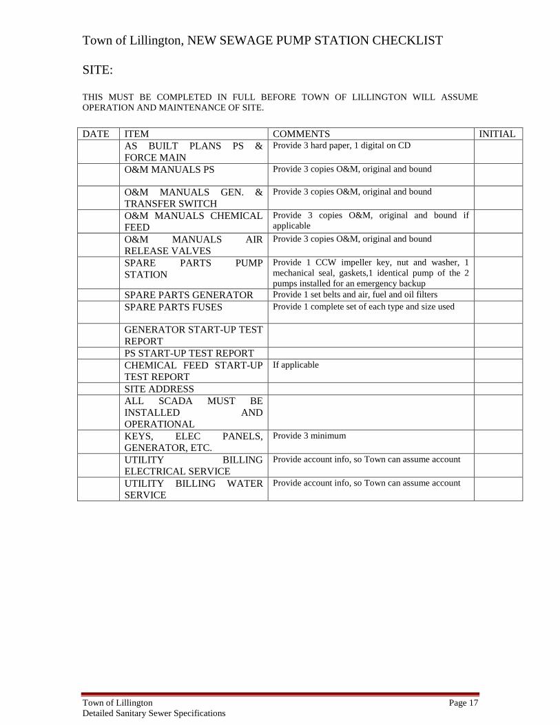
Town of Lillington, NEW SEWAGE PUMP STATION CHECKLIST SITE: THIS MUST BE COMPLETED IN FULL BEFORE TOWN OF LILLINGTON WILL ASSUME OPERATION AND MAINTENANCE OF SITE. DATE ITEM COMMENTS INITIAL AS BUILT PLANS PS &
FORCE MAIN Provide 3 hard paper, 1 digital on CD
O&M MANUALS PS Provide 3 copies O&M, original and bound
O&M MANUALS GEN. & TRANSFER SWITCH
Provide 3 copies O&M, original and bound
O&M MANUALS CHEMICAL FEED
Provide 3 copies O&M, original and bound if applicable
O&M MANUALS AIR RELEASE VALVES
Provide 3 copies O&M, original and bound
SPARE PARTS PUMP STATION
Provide 1 CCW impeller key, nut and washer, 1 mechanical seal, gaskets,1 identical pump of the 2 pumps installed for an emergency backup
SPARE PARTS GENERATOR Provide 1 set belts and air, fuel and oil filters SPARE PARTS FUSES Provide 1 complete set of each type and size used
GENERATOR START-UP TEST REPORT
PS START-UP TEST REPORT CHEMICAL FEED START-UP
TEST REPORT If applicable
SITE ADDRESS ALL SCADA MUST BE
INSTALLED AND OPERATIONAL
KEYS, ELEC PANELS, GENERATOR, ETC.
Provide 3 minimum
UTILITY BILLING ELECTRICAL SERVICE
Provide account info, so Town can assume account
UTILITY BILLING WATER SERVICE
Provide account info, so Town can assume account
Town of Lillington Page 18 Detailed Sanitary Sewer Specifications
II. SEWER MATERIAL STANDARDS 1. GENERAL MATERIAL Current specifications of the American Society for Testing Materials (ASTM), American Water Works Association (AWWA), the American National Standards Institute (ANSI), the American Association of State Highway and Transportation Officials (AASHTO), and Ductile Iron Pipe Research Association (DIPRA) shall apply in all cases where material is covered by an item in these specifications. All material used shall conform fully to these current standards or be removed from the job at the direction of the Public Works Director. Pipe specimens may be subjected to tests by an independent testing laboratory at such time as the Public Works Department may direct or as specified herein. Pipe not meeting these specifications will be ordered removed by the inspector, and such pipe shall be immediately removed from the job site and not transported to any portion of the project being constructed. These specifications are not to be considered as proprietary in any way. When a particular brand is listed, it is only used as an aid in describing the type of material being requested. 2. PIPE MATERIALS (Mains Only)
a. Ductile Iron Pipe and Fittings
Ductile iron pipe and fittings used for sanitary sewers shall be manufactured in accordance with AWWA Standards C-150 and C-110 respectively. The minimum pressure class pipe shall be class 250 or a greater class may be required based upon the depth of cover and laying conditions. Pipe shall be supplied in 18 or 20 foot nominal lengths or less depending on size and class. Pipe and fittings shall have a minimum working pressure of 250 psi, and minimum iron strength of 30,000 psi. Ductile iron may be used for any sewer main 8-inch and larger. Pipe joints shall be the "Push-on" type manufactured in accordance with AWWA Standard C-111-95.
b. Interior Linings for Force Mains, Sewer Mains, Interceptors, and Sewer Service Pipe
All Ductile Iron Pipe and Fittings, in high H2S areas, shall be lined with an amine cured novalac epoxy coating, minimum 40 mils nominal dry film thickness and meet ASTM E 96-93 or latest revision.

Town of Lillington Page 19 Detailed Sanitary Sewer Specifications
c. PVC Gravity Sanitary Sewer Pipe
PVC gravity sanitary sewer pipe and related fittings shall be manufactured in accordance with all the requirements of ASTM D-3034-98 SDR 35 Type PSM polyvinyl chloride sewer pipe. PVC gravity sewer pipe may be used for 6, 8, 10, 12 or 15 inch mains and shall be supplied in suitable lengths and shall be bell-and-spigot joints. ASTM F679-95 shall establish the requirements for 18, 21, 24 and 27-inch diameter PVC, SDR 35 or SDR 26 gravity sewer pipe. The length of joints shall be at least 11 feet for the larger PVC pipe, unless approved differently by the Public Works Director. All fittings shall use rubber gaskets, which conform to the requirements of ASTM F477-99.
d. Steel Pipe (for casing)
Steel pipe for aerial creek crossings shall be high strength steel, helical or straight seam welded manufactured in accordance with ASTM A 139 and consisting of grade “B” steel with a minimum yield strength of 35,000 psi. Boring installations shall be high strength steel, spiral welded or smooth-wall seamless manufactured in accordance with ASTM A252 and consisting of grade 2 steel with a minimum yield strength of 35,000 psi. The minimum casing pipe wall thickness shall be 0.375” for bored encasement in accordance with the table provided in sewer detail. Thicker encasement pipe may be required by the North Carolina Department of Transportation, railroads, or other agencies.
The pipe shall be coated inside and outside, in accordance with AWWA C203-97, ASTM standards and any additional requirements of the N.C. Department of Transportation or the American Railway Engineering Associations' specifications. All encasement pipe must be approved by the appropriate controlling agency (i.e. NCDOT, RR, etc.) prior to order-ing the material.
If the encasement pipe is used to carry a sewer main larger than 8-inch in diameter, then a vent pipe shall be installed in an area where it will not be a hazard to pedestrians or traffic. The vent pipe shall be made from ASTM A139, grade "B" steel, with minimum yield strength of 35,000 psi and coated as described above or factory galvanized. The vent pipe location shall be approved by the appropriate agency prior to installation.
All carrier piping shall be slip joint ductile iron and the inside diameter of the casing pipe shall not be less than 2 inches greater than the largest outside diameter of the joints and couplings for carrier pipe less than 6" O.D., and 4" greater for carrier pipe 6" and larger. It shall, in all cases, be great enough to easily remove carrier pipe without disturbing the casing pipe. The minimum steel casing size for carrier pipe shall be as follows:

Town of Lillington Page 20 Detailed Sanitary Sewer Specifications
Nominal D.I. Steel Casing Min. Wall Thickness Min.Wall Thickness Carrier Pipe Dia. Minimum O.D. For Highways For Railroads (Inches) (Inches) (Inches) (Inches) 3 8.625 0.250 0.250 4 10.750 0.250 0.250 6 12.0 0.250 0.250 8 16.0 0.281 0.312 10 20.0 0.312 0.312 12 24.0 0.312 0.375 15-16 30.0 0.406 0.406 18 30.0 0.406 0.500 20- 21 36.0 0.469 0.500 24 36.0 0.469 0.500 27 42.0 0.562 0.625 30 48 0.625 0.719 33-36 54 0.719 0.719
Both ends of the casing shall be mortared. Metal "spider" pipe alignment devices shall be installed in all casings with a minimum of two spiders per pipe joint one fourth of the pipe joint length in from both the bell and spigot ends. e. PLUG VALVES All plug valves shall meet or exceed the following standards: ANSI flange drilling conforms to ANSI B16.1, Class 125 and ANSI B16.5, Class 150. ANSI/AWWA C517 Eccentric Plug Valves Mechanical-joint end connections conform to ANSI/AWWA C111/A21.11. Grooved joint end connections conform to ANSI/AWWA C606. Direct buried plug valves shall have a 2-inch nut operator with a C.I. valve box and lid marked “Sewer”. Valves installed greater the 4-feet deep shall have an extension on the nut operator. . 3. MANHOLES AND RELATED MATERIALS Manholes will be precast reinforced concrete. Eccentric or concentric cones may be used on up to 12-inch mains. Concentric cones will be used on all 15 inch and larger mains. These different type manholes shall conform to these specifications and the Town of Lillington Standard “Sanitary Sewer Standard Details”. All manholes located outside public right-of-way must be one foot above the 100-year flood or be sealed. Sealed manholes must be vented every 1000 feet. “Candy cane” vent stacks on sewer manholes must be “factory” fabricated and “hot dipped” galvanized, NOT field fabricated and galvanized. All manholes shall be watertight.
a. Interior Linings for Precast Reinforced Concrete Manholes
All sanitary sewer interceptor/outfall manholes and manholes receiving a sanitary sewer force main discharge shall be internally coated with one coat of a 20% solids, deeply penetrating, dual-component polyurea primer (0.5 – 1.0 mils dry film thickness, 150 ft2/gal), one intermediate coat of a

Town of Lillington Page 21 Detailed Sanitary Sewer Specifications
dual component polyurea (50-100 mils dry film thickness, 50 ft2/gal) and one top coat of a 65% solids, two-part polyurea (7.5-10 mils dry film thickness, 125 ft2/gal). All coats can be applied by brush, spray, or roller. Polyurea coatings shall be Duramer 1030 as manufactured by SewerKote, or approved equal.
b. Precast Reinforced Concrete Manholes
The concentric and eccentric manholes shall be designed and manufactured in accordance with ASTM C478-97. Manhole diameters shall be 4, 5, or 6 feet in diameter as determined by the table within Sewer Design standards for main size or depth. The walls shall be a minimum of 5 inches thick and have a 6-inch minimum base. The standard joint shall be sealed with cementitious grout meeting all Federal Specifications. An O-ring or "ram neck" joint seal may be used. All exterior joints shall be wrapped with a butyl resin sealant of 8” width. The "O" ring joint shall conform to the requirements of ASTM C443-98. A flexible rubber boot shall be supplied with the manholes to tie the pipe to the barrel section. These gaskets and clamps shall meet the requirements of ASTM C923.
The manufacturer shall submit drawings showing the reinforcing, pipe openings and other details for approval by the Public Works Director. Also, the manufacturer shall provide certified test reports indicating that the materials comply with the requirements of ASTM C478-97.
c. Related Materials
1) Manhole rings and covers shall be manufactured to the dimensions
shown on the Town’s sanitary sewer details, and shall be made from Class 30 gray iron, meeting the requirements of ASTM A48-94ae1. All covers must be domestically cast and so indicated by manufacturer name and “USA” in castings. Covers shall have “DANGER PERMIT REQUIRED – CONFINED SPACE DO NOT ENTER” cast onto the face. All manhole rings on flat-top manholes shall be cast into the manhole top, as shall be the flange for the vent stack, if applicable. Manhole rings and covers manufactured outside the United States will not be accepted by the Town of Lillington.
2) Manhole steps shall be made from reinforcing steel which is rubber
plastic coated to provide for safer footing. These steps shall be furnished and in accordance with the applicable OSHA regulations. Steps shall also be provided on outside of raised manholes when top elevation is greater than three (3) feet above existing ground elevation. All traffic bearing castings must be Class 35 or greater.
3) Cement used in masonry or reinforced concrete units shall be
Type-I, CSA normal, meeting ASTM C150-99, unless otherwise approved by the Public Utilities Director.

Town of Lillington Page 22 Detailed Sanitary Sewer Specifications
4) Concrete shall be only plant-mixed or transit-mixed concrete conforming to ASTM C33-99ae1 as to aggregates and to ASTM C94/C94M-99e1 for ready-mixed concrete.
Concrete shall be of three types as based on 28-day compressive strength:
Type AA 4500 psi Type A 3000 psi Type B 2500 psi
Concrete shall be air-entrained, unless specified otherwise, with 4 to 6% air. Retarders and accelerators shall be used only as directed by the Engineer.
Concrete used for structures such as sewage lift stations and other reinforced concrete structures shall meet all applicable provisions of the NCDOT specifications regarding the manufacture, delivery and placement.
5) Steel reinforcing for concrete structures shall meet all applicable
provisions of the NCDOT specifications as to manufacture, fabrication and placement.
6) Mortar used for sewer structures shall conform to ASTM
specification C144-99 as to aggregate and strength. Mortar shall be prepared from cement in perfect condition and shall be prepared in boxes for that purpose. No mortar that has stood beyond forty-five minutes shall be used. Proportion by volume for different kinds of work shall be:
Brick Masonry 1 part cement to 2 parts sand Pointing 1 part cement to 1 part sand
7) Rubber boot sleeves shall meet or exceed ASTM C923 for connecting pipes to thru the barrel section of the manhole. Boot sleeves shall have stainless steel expansion bands and pipe clamps that meet or exceed ASTM C923 and A167.
8) Manhole inverts shall be constructed with a width equal to that of
the effluent pipe, height to the springline and invert “shelves” from that point upward at a 60 deg. angle to the manhole walls. The invert shall be brushed and troweled that a minimum energy loss occurs in the manhole from invert roughness. “Bowl” shaped invert will not be allowed.
4. MISCELLANEOUS MATERIALS
a. PVC Sewer Service Pipe

Town of Lillington Page 23 Detailed Sanitary Sewer Specifications
PVC sewer service pipe shall be schedule 40 PVC including the clean-out stack provided that a brass clean-out slotted plug for location purposes when clean-out flush with finished grade is used. A PVC cap may be used when the clean-out extends 4-inches or more above finished grade.
b. PVC Sewer Pipe and Saddles
PVC sewer pipe, saddles and adapters shall not be allowed on new construction. If saddles are used on existing sewer, Contractor will submit details to the Town of Lillington for approval prior to installation.
c. Sewer Force Main Material
Sewer force mains shall be ductile iron and or PVC sewer pressure pipe. Fittings at bends and reducers shall be ductile iron mechanical joint.
d. Sewer Air Release/Vacuum Breaker Valve Material
Air release/vacuum breaker valves on sewer force mains shall be in accordance with the “Standard Sanitary Sewer Details”. Air vent shall be filtered to prevent odor with an approved device.
e. All bends constructed on force mains shall include concrete thrust blocks.
f. Individual services shall be prohibited without the written permission of the Public Works Director or designee. In the event such service is allowed, the pumping station shall be a grinder positive displacement type and shall be maintained by the Owner. The Town of Lillington takes will not be responsible for these individual stations.
III. CONSTRUCTION SPECIFICATIONS FOR SEWER MAINS The requirements contained in this section shall apply to sanitary sewer main installations constructed for the Town of Lillington or for private Developers who may or may not dedicate the sewer improvements to the Town of Lillington. All necessary construction permits must be obtained before construction may begin in accordance with the North Carolina State Law. A sewer plug must also be installed to prevent discharge to the Town of Lillington wastewater collection system prior to acceptance of work performed. Any Contractor performing work shall have on each job site a copy of these specifications and all permits, encroachments, etc… 1. SCOPE OF WORK
a. The Contractor shall furnish all materials, equipment, and labor for excavation, installation, backfilling of sewer mains and related appurtenances as shown on the plans. The Public Works Department will provide inspections on main extension projects.

Town of Lillington Page 24 Detailed Sanitary Sewer Specifications
b. It shall be the Contractor's responsibility to notify the Public Works Department at least 48-hours in advance of beginning any construction work on any project. The Contractor must call the Public Works Department and give the location, project name, and individuals’ name, and company name, and start date and indicate if it involves a sewer extension.
c. Once construction has begun, the Contractor shall contact Public Works at
(910) 893-3607 each morning by 9:00 a.m. to notify the location and type of work to be accomplished that day. The Town of Lillington requires a 48-hour notice prior to an inspection. Any work requiring inspector’s observation outside of the normal workday shall not be done without prior written approval from the Public Works Director and will be charged to the Contractor at the inspector’s overtime rate of pay.
d. If a Developer, Engineer or Contractor proceeds with the main installation
prior to permit issuance, and the Town of Lillington requires the work to be reinstalled, the Developer, Engineer or Contractor shall be fully liable for all actions and costs, including prosecution by the Town of Lillington and/or the State for proceeding with installation prior to issuance of appro-priate permit(s).
"Field changes" are not considered approved by the Public Works Department unless revised plans have been submitted to the Public Works Department, reviewed and approved. Therefore any Contractor that proceeds with construction prior to this approval is at his/her own risk.
2. GENERAL TESTING REQUIREMENTS
a. The Town of Lillington shall require the Contractor to perform, such destructive and nondestructive testing, as it deems necessary in order to inspect the materials and workmanship. See specific testing requirements within this section. These tests shall be in accordance with the procedures established by ASTM and AASHTO. The Town of Lillington shall reserve the right to modify the procedures.
b. All new sanitary sewer mains must be cleaned to the satisfaction of the
inspector by jetting or balling prior to final inspection and acceptance by the Town of Lillington.
c. Prior to final acceptance, all sanitary sewer mains shall be camera
inspected at the Contractor/Developers expense and three (3) copies provided in digital format to the Town of Lillington Public Works Department. Failed inspections will require a follow up inspection and subsequent re-inspection fee.
3. SEWER CONSTRUCTION PLUGS

Town of Lillington Page 25 Detailed Sanitary Sewer Specifications
Mechanical plugs (non-pneumatic) must be installed throughout the time of construction of any sanitary sewer extension. Plugs are to be installed on the downstream end of the new main at the first manhole from the existing tie-in, until final acceptance. All plugs must be securely tied off with steel cable within the manhole and must have a secure marking attached to the plug indicating the utility Contractor to whom the plug belongs. All plugs must be monitored during construction to insure the plug is functioning as required. Prior to removing the plug, all accumulated water/debris must be removed and disposed of properly by the Contractor. All plugs must be removed by the Contractor upon acceptance that the sewer facilities are sufficient and functionally complete to accept flow and PRIOR to the mains above the plug location being placed into service and/or accepting any flow of sewage. 4. HANDLING AND STORAGE OF MATERIALS
a. The Contractor shall be responsible for the shipping and storing of all sewer materials. Any material which is damaged or defective shall be replaced by the Contractor at the Contractors' own expense.
b. The loading and unloading of all pipe, manholes and other accessories shall be in accordance with the manufacturer's recommended practices and shall at all times be performed with care to avoid any damage to the material.
c. The Contractor shall locate and provide the necessary storage areas for materials and equipment. If private property is being used for storage areas, then the Contractor must have the written consent from the Owner. Without this written consent, all material and equipment shall be stored within the existing rights-of-way and easements of the project. Any pipe strung out can not be left overnight; it must be delivered to and removed from the job site each day.
d. All materials, once on the job site, shall be stored in accordance with the
manufacturer's recommendations. All PVC sewer pipe shall be protected from the sun's ultra violet rays if stored on the job site longer than twenty days. Pipe which has prolonged exposure to the sun may be rejected for use by the Town of Lillington.
e. All pipes shall be kept free of dirt and other debris. Any damage relating
to the coating of the various materials for sewer and water mains shall be repaired in a manner approved by the Town of Lillington. Machined manhole frames and covers shall remain intact until construction is complete.
f. The Contractor shall be responsible for safeguarding and protecting all
material and equipment stored on the project. The Contractor shall be responsible for the storage of materials in a safe and professional manner

Town of Lillington Page 26 Detailed Sanitary Sewer Specifications
to prevent injuries, during and after working hours, until the project is complete.
5. BARRICADES, SIGNS AND STREET PROVISIONS
a. Signs, barricades, warning lights, guard rails and flaggers shall be employed as necessary when construction endangers either vehicular or pedestrian traffic. These devices shall remain in place until the traffic may proceed normally again. The Contractor shall hold the Town of Lillington harmless for any damages or injuries caused by the construction of sewer mains.
b. Detours shall be set up and maintained by the Contractor under the
direction of the Town of Lillington and/or North Carolina Department of Transportation. Notice must be given a week in advance of the detour so that necessary notification of the traveling public may be made by the Contractor to the public. The Contractor will furnish all barricades, signs, lights and other safety devices to protect his/her construction. The Contractor is in no way relieved of liability for providing this protection because others approve the detour.
c. Construction work zone signs and signing procedures shall conform to the
Manual of Uniform Traffic Control Devices and supplements and to all applicable federal, state and local codes. The Contractor shall be responsible for securing the necessary permits for all work to be performed in the public rights-of-way.
6. PROPERTY PROTECTION Trees, fences, poles and all other property shall be protected unless their removal is authorized, and any property not authorized for removal, but damaged by the Contractor, shall be restored by the Contractor to the Owner's satisfaction. Existing manholes within the work zone and outside of the pavement shall be protected by orange safety fence. At no time is work, storage of material or construction access to occur on private property unless the work is within a recorded easement or with prior written authorization. 7. GENERAL CONSTRUCTION SAFETY
a. The Contractor and any Sub-contractors shall be responsible for the total compliance with all federal, state and local ordinances, laws and regula-tions as related to safe construction practices and to protecting the employees and the public's health and safety.
b. The Contractor shall ensure that all Occupational Safety and Health
Administration (OSHA) regulations and standards are followed during all phases of the construction project.
c. The Town of Lillington shall not be responsible for Contractor’s
adherence to OSHA regulations and standards. However, the Town of

Town of Lillington Page 27 Detailed Sanitary Sewer Specifications
Lillington may report known violations or unsafe practices to the appropriate enforcement agency.
d. The Contractor shall furnish safety equipment necessary to inspect the
work including, but not limited to ladders, confined space entry tripod/harness, gas detectors/oxygen sensors, blowers, etc.
e. Under no circumstances shall any roadway or driveway be blocked
overnight. The roadway shall be open for access to residents, businesses, emergency vehicles, garbage pick-up, school buses etc. Furthermore, no driveways shall be blocked overnight without the express permission of the Town of Lillington Public Works. The Contractor shall notify the Public Works Department, School Bus Garage, and Emergency Services of any temporary road closings and/or detours.
8. ENCROACHMENT CONTRACTS AND PERMITS
a. Prior to actual construction, the Contractor/Engineer shall acquire the necessary encroachments from NCDOT when working within the rights-of-way of state system roads or highways. A copy of the encroachment permit shall be kept on the job site at all times.
b. The Contractor/Engineer shall be responsible for securing all other local
and state and federal permits required for the utility construction. The Contractor must have an approved set of permitted construction plans on site at all times.
9. PAVEMENT REMOVAL AND REPLACEMENT
a. All pavements to be removed shall be cut along straight lines with the appropriate saw cut machine. All material removed must also be removed from the job site the same day and disposed of properly.
b. All cuts of Town of Lillington streets must be patched the same day with
ABC Stone or 2 inches of SF 9.5A asphalt. Once work has been completed, or if a hazard exists, all temporary patches shall be replaced with SF 9.5A asphalt. All work from patching shall be cleaned up at the same time of patching.
c.. Asphalt compaction shall be done with a gasoline or diesel powered
smooth drum asphalt roller.
d. Pavement cuts within NCDOT Right of Way shall not be performed without the proper encroachment permits on site. All patching of NCDOT pavements shall conform to the approved on site encroachment permit.
10. CONSTRUCTION WATER

Town of Lillington Page 28 Detailed Sanitary Sewer Specifications
The Town of Lillington Public Works Department does not provide free or otherwise unmetered construction water for any construction project. Contractors are responsible for requesting a hydrant meter from Town Hall (deposit required). Hydrant meters may only be moved with the express written permission of the Public Works Department. Contractors are responsible for adequate construction water for their job sites. Note: Individuals caught using water unmetered and/or unauthorized by the Public Works Department will be prosecuted to the fullest extent of the law. 11. EXCAVATION
a. Prior to any excavation or construction, the Contractor shall be responsible to contact NC 811 for the location of all existing utilities in the field. If help is needed in locating utilities operated by the Public Works Department, the Contractor should contact the Town of Lillington Public Works Department (910) 893-3607.
b. Trench width shall be a minimum of twelve inches plus outside diameter
of pipe and a maximum of twenty-four inches plus outside diameter of pipe, unless OSHA requires additional trench width. Trench width shall be measured between the faces of the cut at the top elevation of the pipe bell.
c. Trench bottom conformation, where no special bedding is required, may
be referred to as flat bottom where the trench bottom is excavated slightly above grade and cut down to pipe grade by hand in the fine-grading operation. Where the trench bottom is inadvertently cut below grade, it shall be filled to grade with an approved material and thoroughly tamped.
d. The Contractor shall, at the Contractor's own expense, keep all trenches
free from water during the excavation for construction of sewer mains. The water shall be pumped out of the trench or build check dams to keep it out of the ditch in such a manner as not to cause injury to the public health, private property or the work in progress. Erosion control measures shall be taken during this pumping.
e. In trenches where water is present or dewatering is required, the trench
shall be stabilized with #57 or #67 stone. When the Contractor encounters material during trench excavation, at the opinion of the inspector or Public Works Director, that is unsuitable (i.e. "muck"), this material shall be replaced with material that is considered suitable prior to the pipe laying operations. In this case, construction fabrics may be required to prevent the migration of side support away from the pipe. Water shall be filtered prior to discharge to prevent sediments from escaping the site. The Contractor shall discharge said water in a manner not to erode the soil.

Town of Lillington Page 29 Detailed Sanitary Sewer Specifications
f. Safety and convenience of the public necessitate that all work, including excavation, be done in such a manner as to cause minimum traffic interruption, both pedestrian and vehicular. Utilities such as fire hydrants, valves, etc., shall be accessible at all times. Gutters and drains shall be left open and clear at all times, and the Contractor shall be responsible for all drainage around his work. Unless specifically waived by the Public Works Director, provisions shall be made to maintain vehicular traffic on all streets in which work is in progress, and suitable walkways shall be maintained for pedestrian travel.
g. Under no circumstances shall any roadway or driveway be blocked
overnight. The roadway shall be open for access to residents, businesses, emergency vehicles, garbage pick-up, school buses etc. Furthermore, no driveways shall be blocked overnight without the express permission of the Town of Lillington Public Works. The Contractor shall notify the Public Works Department, School Bus Garage, and Emergency Services of any temporary road closings and/or detours.
h. Should extended wet weather occur during the construction of the sanitary
sewer, the Contractor and/or Owner shall be responsible for any additional stone to be installed to ensure the roadway is passable.
i. Sheeting or bracing shall be used wherever necessary to prevent failure of
the trench banks. All sheeting shall conform to AASHTO and OSHA safety standards. The decision of the Engineer relative to bracing for the protection of property of the Town of Lillington shall be binding upon the Contractor. The removal of sheeting shall be done in such a manner as to minimize the loss of friction between the backfill and trench walls.
12. TRENCH PREPARATION
a. Trench excavation shall conform to the line and depth shown on the plans. The trench shall be properly braced and shored so the workers may work safely and efficiently. When water is being pumped from the trench, the pump discharge shall follow natural drainage channels, drains or storm sewers. In no case may trench water or groundwater be pumped into or allowed to enter the sanitary sewer system. See erosion control section for appropriate siltation prevention measures prior to pumping.
b. The width and type of trench may vary with the depth of cut, and the
trench shall be constructed in accordance with the dimensions and other information.
c. Pipe clearance in rock shall be a minimum of six inches on each side and
bottom for mains fifteen inches in diameter and less. For larger size mains, the minimum clearance shall be nine inches on the sides and bottom.
d. If unstable conditions are encountered, the trench shall conform to the
requirements as stated in these specifications.

Town of Lillington Page 30 Detailed Sanitary Sewer Specifications
13. PIPE INSTALLATION
a. The pipe material listed above shall be installed in accordance with the manufacturer's recommendations and the requirements of these specifications.
b. All gravity sanitary sewer mains and manholes shall be laid to the line and
grade shown on the plans. Force mains shall be installed at the minimum depth indicated on the plans. In no case shall sewer mains have less than 3-feet of cover unless the piping material is ductile iron.
c. No deviations from line and grade shall be made, unless the Public Works
Department or Engineer has approved them and they have been identified on the construction drawings initialed by the individual authorizing the change and on the "as-built” plans.
d. The sewer pipe installation shall start at the outlet end and proceed
upstream to the termination of the project as shown on the plans. The bell ends shall point upstream. Exceptions to this provision will be considered on a case by case basis when requested in writing by the Owner of the development at the time construction plans are submitted to the Town of Lillington for review and approval. The development Owner must agree to hold the Town of Lillington harmless. He must accept full responsibility for compliance with state and federal regulations of the Clean Water Act, including any associated penalties which could reach up to $25,000/ day, for the release of wastewater from sanitary sewer to the environment, which are not connected to existing sewer due to the granting of an exception to the pipe laying sequence required in the Public Works Specifications. The development Owner must further agree to not request building permits, if an exception is granted for that portion of the development, until connecting sewer is constructed and accepted by the Town of Lillington.
e. While working on any part of an existing sewer main, the Contractor shall
maintain the existing sewage flow. No discharge of sewage to the storm waters will be allowed. Water for the flushing of new sanitary sewer mains must be obtained through a fire hydrant meter and must be pumped out and may not be discharged into the sanitary sewer system. Construction requiring existing sewer flow to be pumped from existing manholes shall be the responsibility of the Contractor and must be approved prior to proceeding by the Public Works Director or the Town of Lillington Inspector.
f. After the trench foundation has been properly graded with bell holes, the
pipe shall be carefully lowered into the trench with approved methods. Under no circumstances shall the pipe or accessories be dropped or dumped into the trench. All damaged pipe shall be properly repaired or replaced at the Contractor's expense.

Town of Lillington Page 31 Detailed Sanitary Sewer Specifications
g. The pipe interior shall be kept clean before and after laying by means approved by the Public Works Director or Engineer. Pipe ends shall be plugged at the end of each workday or when work is temporarily stopped. The plugs shall be watertight so the water and debris will be kept out.
h. When installing a sewer main, the horizontal separation from any water main shall be 10-feet or 24-inches vertically with water over sewer. If this separation cannot be maintained due to existing conditions, the variation allowed is the water main in a separate trench with three feet of separation and the elevation of the water main at least 24-inches above the top of the sewer and both water and sewer must be Ductile Iron pipe. All distances are measured from outside diameter to outside diameter. If for any reason separation cannot be maintained it will be the reasonability of the Contractor to upgrade both lines to ductile iron regardless of whether either the water or sewer line previously exists for the entire length of the separation discrepancy. This will ensure that all parties concerned will be within minimum NCDENR requirements.
i. When a water main crosses over a sewer main, there must be twenty four
inches of vertical separation. If the water main must go under the sewer main, both these lines must be of ferrous material for a distance of ten feet on either side of the crossing with a 24-inch separation. The crossing of other underground pipe requiring less than a minimum of twenty four inches of vertical separation the area must be of ductile iron pipe for ten feet in both directions of both pipes and the sewer be encased in sleeves extending 10 feet in both directions and the water main be ductile iron. The Public Works Director must approve any changes in these clearances. All crossings within these vertical clearances shall be filled with #57 or #67 stone. All distances are measured from outside diameter to outside diameter.
j. Railroad crossings shall be made following all precautionary construction
measures required by the railroad officials.
k. All sewer crossings under state system roads shall be made in accordance with the requirements of NC DOT as defined in their encroachment permits.
l. Where conditions are, in the opinion of the Public Works Department or
Engineer, unsuitable for laying pipe because of weather or trench condi-tions, the Contractor shall be required to cease work until permission is given by the Public Works Department or Engineer for work to commence again, providing such conditions have been corrected.
15. LAYING REINFORCED CONCRETE SEWER PIPE
a. Pipe support for reinforced concrete sewer pipe shall provide uniform bearing for the pipe barrel along its entire length. Particular care shall be taken to compact soil under and around the curve of the pipe to give

Town of Lillington Page 32 Detailed Sanitary Sewer Specifications
maximum support. Select soil compacted to 90% of maximum Proctor Density shall reach to a point one foot above the top of the pipe.
b. Pipe bedding classes for reinforced concrete pipe (as defined for these
specifications) shall be as follows, and it shall be mandatory for the Contractor to employ the correct bedding within the limits defined in the bedding tables included herein.
1) Class D bedding is that condition existing when the trench bottom
is excavated slightly above grade and cut to finished grade by hand. Bell holes are dug, and the pipe bears uniformly along its entire length.
2) Class C bedding is that condition existing when the trench bottom
is undercut a minimum of four inches below the pipe bell and filled with #67 stone to the pipe grade in such a manner that the pipe will be bedded in stone to a vertical height equal to 1/6 the outside diameter of the pipe barrel.
16. LAYING PVC GRAVITY SEWER PIPE The foundation for PVC gravity sewer pipes shall be a firm flat bottom trench of 4 inches of Class I material as defined in ASTM D2321-89 (1995) compacted with bell holes. Class II material may be used if Contractor can verify that this type of soil is native to the site by having soil tests made by a soil-testing agency. 17. LAYING DUCTILE IRON SEWER PIPE
a. Ductile iron pipe shall be installed in accordance with the requirements of AWWA Standard C-600-87.
b. Sewer pipe shall be laid to the line and grade shown on the plans. There
shall be a minimum horizontal separation between water and sewer utilities of ten feet and a vertical separation of 24-inches.
c. Protection shall be afforded to all underground and surface structures
using methods acceptable to the Public Works Director or Engineer. This protection shall be furnished by the Contractor at the Contractors' own expense.
d. Deviation from line and grade may be made on revised plans upon
approval by the Public Works Department and identified on “as built” plans when such deviations arise from grade or line conflicts with existing utilities, structures or other sources of conflict.
e. Subsurface explorations shall be made by the Contractor where it is
necessary to determine the location of existing pipes, valves or other underground structures.

Town of Lillington Page 33 Detailed Sanitary Sewer Specifications
f. After the foundation has been properly graded, bedded when applicable,
and the bell holes dug, the pipe and accessories shall be carefully lowered into the trench by approved methods. Under no circumstances shall the pipe or accessories be dropped or dumped into the trench. All damaged pipe and accessories shall be removed from the job. All damaged pipe shall be replaced at the expense of the Contractor.
g. Laying of pipe and jointing of pipe shall be done according to
manufacturer's recommendation with care being taken to provide uniform bearing for the pipe. Bell and spigot of pipe shall be cleaned and properly lubricated where a mechanical joint or a "push on" type joint is employed.
h. Open ends of pipe shall be plugged with a standard plug or cap at all times
when pipe laying is not in progress. Trench water shall not be permitted to enter pipe.
i. Bell ends will face the direction of laying which must be upgrade unless
otherwise directed by the Public Works Director or Engineer.
Where conditions are, in the opinion of the Town of Lillington Inspector, unsuitable for laying pipe because of weather or trench conditions, the Contractor shall be required to cease work until permission is given by the Town of Lillington Inspector for work to commence again providing such conditions have been corrected.
18. SEWER LATERALS
a. Pipe for 4-inch sewer laterals shall be PVC pipe, DIP or CIP. Where installation by boring is specified, four-inch ductile iron pipe shall be used. DIP or CIP (4”only) must be used for deep or shallow installations under the same standards as sewer mains. Aerial service installations shall be constructed of 4” DIP. A minimum grade of 1% shall be maintained with four and six-inch pipe. Each lateral shall be sealed at the end with an approved watertight plug. A six-inch service lateral must connect to a manhole. All laterals shall be left exposed until the inspectors can verify the installation of each plug. It is the Contractors responsibility to coordinate these inspections with the Town of Lillington Public Works. Laterals which are covered up prior to inspection shall be subject to excavation at the Contractors expense to provide for a visual inspection.
b. Each sewer lateral shall be installed from the main to the street right-of-
way line where a one-piece combination wye and cleanout stack will be installed. The wyes on the laterals shall be sealed at the property line with a permanent plug.
c. Trench support, bedding and backfill for laterals shall conform to the same
specifications as those for sewer mains. The Contractor shall properly
Town of Lillington Page 34 Detailed Sanitary Sewer Specifications
backfill under all wye and lateral connections at the main and shall be backfilled with #67 or #57 stone.
d. Where laterals are bored, the face of the bore cut shall be a distance of five
feet from the edge of the pavement on either side, unless approval to the contrary is given by the Public Works Director.
e. Sewer laterals four inches in diameter shall be connected to the main by
means of an in-line wye or a tap and saddle, installed over a hole cut in the top quadrant of the main at an angle of forty-five degrees, with respect to direction of flow. The hole shall be cut with a mechanical circle type saw cutter designed for the particular use and rendering a smooth, uniform cut with no damage to the main and which retrieves the coupon.
f. All 4" sewer services may be tapped directly into 6, 8, 10, and 12-inch
mains or manholes. Taps can only be made by using a mechanical tapping machine or other approved device. All sanitary sewer service connections 6 inches and larger shall be made into manholes only. Service clean-outs shall be located at the right-of-way line or the easement boundary line. The maximum vertical drop for 4-inch and 6-inch service into a manhole shall be 30inches. Any greater height will require an inside drop. (See Sanitary Sewer Standard Details)
g. All laterals tapped on newly constructed mains shall be air tested with the
main. All laterals tied to a newly constructed manhole shall be vacuum tested with the manhole or conduct a separate air or water head test before any plumber connections are made.
19. MANHOLES
a. Manholes on all line twelve inches in diameter or smaller shall have a minimum inside diameter of four feet.
b. Inverts shall be constructed with a width equal to that of the effluent pipe,
height to the spring line and invert "shelves" from that point upward at 60 deg. to manhole walls, it shall be so brushed and troweled that a minimum energy loss occurs in the manhole from invert roughness. The maximum grade on an invert of less than 2.5 feet shall be no greater than 6 inches across the manhole. “Bowl” shaped inverts shall not be allowed in the sanitary sewer collection system.
c. All manholes in road right–of–ways will be flush with grade not
withstanding 100-year flood requirements. In easements, manholes will be a minimum of 12 inches above ground.
d. All new manholes must be vacuum tested in accordance with the
procedure. The Contractor shall furnish all labor, equipment, and any appurtenant items necessary to satisfactorily perform the vacuum test. All equipment will be approved for vacuum testing.
All lifting holes shall be plugged with an approved non-shrink grout.

Town of Lillington Page 35 Detailed Sanitary Sewer Specifications
All pipes entering the manhole shall be plugged. The Contractor shall securely brace the plugs to keep them from being drawn into the manhole. All service connections tied to manholes shall also be vacuum tested with the manholes.
The test head shall be placed inside the top of the cone section of the manhole and the seal inflated in accordance with the manufacturer’s recommendations.
A vacuum of 10-inches of mercury shall be drawn and the vacuum pump shut off. Inflate the compressor band to affect a seal between the vacuum base and the manhole cone section. Connect the vacuum pump to the outlet port with the valve open. With the valves closed, the time for the vacuum to drop to 9-inches of mercury shall not be less than that shown in the following table.
Manhole Depth Diameter of Manhole 48”Dia. 60”Dia. 72”Dia 10 Ft. or Less 60 Sec. 75 Sec. 90 Sec.
>10 Ft. but<15 Ft. 75 Sec. 90 Sec. 105 Sec. >15 Ft. 90 Sec. 105 Sec. 120 Sec.
(Times shown are minimum elapsed times for a drop in vacuum of 1-inch of mercury).
If the manhole fails the initial test, necessary repairs shall be made with an approved non-shrink grout. Re-testing shall proceed and continue until a satisfactory test is accomplished.
e. All manhole rings on manholes other than flat-tops shall be bolted to the
cone section and sealed down with asphalt cement or “ram-neck. f. All manhole joints must be waterproofed with asphalt cement or “ram-
neck”. All exterior joints shall be wrapped with a butyl resin sealant of 8” width.
g. All main and service pipe connections into manholes must be cored with a
concrete coring machine and the pipe connection must be made with a flexible rubber boot.
h. Adjustment rings used within streets shall be fixed with mortar.
20. BACKFILLING
a. The haunch for PVC pipes shall be with #67 or #57 stone (Class I material) 4 inches below and up to the springline of the pipe. Care shall be taken to work the haunch well under the bottom of the pipe. The initial

Town of Lillington Page 36 Detailed Sanitary Sewer Specifications
and final backfill shall be with suitable native material. No rocks, boulders or stones four inches or larger shall be included in the backfill. The haunch shall be tamped to 95% standard Proctor density in six-inch lifts.
b. For PVC sewer installations, Class II material may be allowed for the
bedding, housing and initial backfill if the Contractor can verify that this type of soil is native to the site by having soil tests made by a soil-testing agency. Soil sample borings shall be taken as directed by the Town of Lillington inspector to a depth equal to or greater than the trench bottom elevation shown on the plans or in the specs. The results must be approved by the Public Works Director prior to pipe installation. The bedding and backfilling shall be in conformance with ASTM standards and the various soil classes are defined below:
1) Class I - Angular, 6 to 40mm (1/4 to 1 1/2 inch), graded stone, including a number of fill materials that have regional significance such as coral, slag, cinders, and crushed stone and crushed shells.
2) Class II - Course sands and gravel’s with maximum particle size of 40mm (1 1/2 inch), including variously graded sands and gravel’s containing small percentages of fines, generally granular and non-cohesive, either wet or dry. Soil Types GW, GP, SW and SP are included in this class. (GW - well graded gravel, GP - poorly graded gravel; SW - well graded sand, SP - poorly graded sand.)
3) Class III - Fine sand and clay type gravel’s, including fine sands, sand clay mixtures and gravel-clay mixtures. Soil Types GM, GC, SM and SC are included in this class. (GM - silty gravel, GC - clayey gravel, SM - silty sand, SC - clayey sand.)
4) Class IV - Silt, silt clays and clays, including inorganic clays and silts of medium to high plasticity and liquid limits. Soil Types MH, ML, CH and CL are included in this class. These materials are not recommended for bedding, haunching or initial backfill on PVC pipes. (MH - silt soil with high liquid limit, ML - silt soil with low liquid limit, CH - clayey soil with high liquid limit, CL - clayey soil with low liquid limit.)
c. All backfill shall be compacted in six-inch lifts measured from the
foundation to one foot above the top of the pipe and then in twelve-inch lifts to the top of the trench when in easements. Sewer mains in street rights-of-way shall be compacted in six-inch lifts all the way to the top of the trench.
d. Material for backfilling shall be approved by the inspector. In areas where
settlement or bearing capacity are not a major consideration, the Engineer may give permission for a low grade of material to be backfilled from a point two foot above the top of the pipe, but in no event will excavated rock larger than four inches at any point be used for backfill material.

Town of Lillington Page 37 Detailed Sanitary Sewer Specifications
e. Where backfill material is unsuitable, in the opinion of the Public Works Director or Engineer, the Contractor may be directed to dispose of the unsuitable material and provide material suitable to the Public Works Director or Engineer.
f. All backfill shall be compacted in (6) six inch lifts measured from the pipe
foundation upward, except as noted in section (c) above. Backfill for roadway shall be compacted to at least 95% of maximum soil density in those areas where the supporting capacity of the soil is of prime consideration. Laboratory determination of maximum soil density will follow the procedure of AASHTO T99-86. Field determination of the density of the soil in place shall follow the procedure of AASHTO T191-86 or T204-86. The result of any one test may be a minimum of 90% of maximum density, but the average of any three tests in an area shall be 95% of maximum density. All tests shall be conducted at the direction of the Town of Lillington Inspector, borne by the Contractor with the provision that the Town of Lillington will test an area two times only where both tests fail. The Contractor shall then be required to submit satisfactory evidence that his ditch compaction meets the specifications.
21. SURFACE RESTORATION
a. All disturbed surfaces and property thereon, shall be restored to a condition equal to that existing before construction began, and the Contractor shall maintain and be responsible for all ditches, paved streets, curbs, gutters and/or sidewalks until the Contractor’s one year warranty expires. It is suggested the Developer/Contractor video the proposed construction area prior to beginning work. The Contractor, with permission of the inspector, may place temporary or permanent asphalt material in pavement cuts. Asphalt compaction shall be done with a gasoline or diesel powered smooth drum asphalt roller.
b. All easements will be seeded in accordance with the approved
Sedimentation and Erosion Control Plan, and left so conventional mowers can mow them, unless approved by the Public Works Department or unless NCDENR requires some other form of rip-rap or other specified material. In remote areas, easements will be seeded with a quality fescue grass. In residential areas, easements will be seeded with Contractors grass seed mix unless directed otherwise by the Public Works Director. The Contractor shall guarantee a good uniform stand of grass and shall reseed any bare or thin spots. The Contractor will be responsible for a one-year warranty on materials and workmanship, which shall begin after final acceptance by the Town of Lillington.
22. EROSION CONTROL Erosion control measures shall be performed by the Contractor, conforming to the requirements of, and in accordance with plans approved by the State of North Carolina Department of Environment and Natural Resources, North Carolina Sedimentation Control Commission, Town of Lillington., and as per the erosion control plan portion of

Town of Lillington Page 38 Detailed Sanitary Sewer Specifications
the construction drawings and these specifications. The Contractor shall not allow mud and debris to accumulate in the streets. The sedimentation and erosion control plan and permit shall remain on site at all times. Should the Contractor pump water from trenches during construction, appropriate siltation preventative measures shall be taken prior to the entry into any storm drain or stream. All materials used for erosion control shall be approved by the Engineer prior to installation by the Contractor. Temporary and permanent erosion control measures shall be shown on the plans. Temporary and permanent erosion control work shall be coordinated throughout the project to provide effective and continuous erosion control throughout construction and post construction, which minimizes siltation of streams, lakes, reservoirs, other water impoundments, ground surface, or other property. Seeding and mulching shall be carried out immediately behind construction. Temporary erosion control measures shall include but not be limited to swaled easements, silt fences, crushed stone check dam devices, silt basins (sedimentation traps), mulching, earth berms, and rip-rap. Permanent erosion control measures shall include but not be limited to swaled easements, rip-rap, and seeding of disturbed areas. Erosion and siltation shall be controlled on projects by using swales to control run-off and convey run-off to controlled discharge points, by silt fences, rip-rap, crushed stone, and earth berms to contain silt, with pipe culverts where major access or haul roads cross drainage ditches or streams, silt basins where pipe lines cross drainage ditches or streams, and seeding and mulching will be performed as soon after pipe installation as possible. When temporary measures are removed after completion of the project the disturbed area must be stabilized, as required by the approved erosion control and sedimentation plan. All temporary erosion control measures must be removed and disposed of by the Contractor within the one year anniversary date of the completion of the project but after the establishment of ground cover. Failure of the Developer/Owner/Contractor to remove these devices may result in the Town removing the devices and assessing the Developer/Owner. 23. MAINTAINING SERVICE When replacing or extending sanitary sewer mains, the Contractor shall maintain existing service to all property being served. 24. GUARANTEE The Contractor shall guarantee all material, equipment and workmanship for a period of at least one year after final acceptance by the Town of Lillington. The Public Works Department is responsible for the issuance of final acceptance letters of sewer utilities by the Town of Lillington. 25. WETLAND/ STREAM BUFFERS Conditions of 401/404 permits shall be strictly followed to the satisfaction of Corp of Engineers. All Cape Fear Riparian buffers shall be maintained as required by NCDWQ.
Town of Lillington Page 39 Detailed Sanitary Sewer Specifications
26. TEST AND INSPECTION
a. Sewer lines shall be visually inspected from every manhole by use of television cameras or other devices for visual inspections, and the lines shall exhibit a fully circular pattern when viewed from one manhole to the next. In addition to a visual inspection deflection tests shall be performed on all pipes.
b. The test shall be conducted after the final backfill has been in place at least 30 days. The deflection test shall be conducted using a rigid ball or mandrel, it shall have a diameter equal to 95% of the inside diameter of the pipe. The test shall be performed without mechanical pulling devices. No pipe shall exceed a deflection of 5%, calculated by using the base inside diameter as furnished by ASTM. Lines that do not exhibit a true line and grade and have structural defects shall be corrected to meet these specifications. The mandrel and proving ring will be furnished by the Contractor. The latest applicable ASTM shall be used.
c. Sanitary sewer lines will be tested by using the low-pressure air test.
Sewer laterals will be tested along with the main. It is imperative that proper plugs be installed on the laterals at the cleanout stack. All plugs should be properly installed to withstand the test pressure. Mechanical plugs must be installed throughout the time of construction of any sanitary sewer extension, until final acceptance. All plugs must be securely tied off with steel cable within the manhole and must have a secure marking attached to the plug indicating the utility Contractor to whom the plug belongs. All plugs must be removed by the Contractor upon acceptance that the sewer facilities are sufficiently and functionally complete so as to accept flow and PRIOR to the mains above the plug location being placed into service and/or accepting any flow of sewage.
d. The low-pressure air test in accordance with ASTM F1417 or C924
(F1417 for PVC and Ductile; C924 for Concrete Pipe) will be used on all mains and laterals. Prior to testing, the main shall be clean of debris (to the satisfaction of the inspector) and flushed with water. In doing the air test, it is necessary that plugs be secured properly and braced. In doing the air test, no person will be allowed in the main while it is pressurized. The line is to be pressurized to 4 psi initially and stabilized. After stabilization, the pressure will be decreased to 3.5 psi, and the inspector will determine how long it takes for the pressure in the line to drop to 2.5 psi.
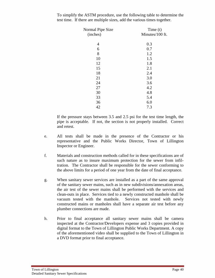
Town of Lillington Page 40 Detailed Sanitary Sewer Specifications
To simplify the ASTM procedure, use the following table to determine the test time. If there are multiple sizes, add the various times together.
Normal Pipe Size Time (t)
(inches) Minutes/100 ft. 4 0.3 6 0.7 8 1.2 10 1.5 12 1.8 15 2.1 18 2.4 21 3.0 24 3.6 27 4.2 30 4.8 33 5.4 36 6.0 42 7.3
If the pressure stays between 3.5 and 2.5 psi for the test time length, the pipe is acceptable. If not, the section is not properly installed. Correct and retest.
e. All tests shall be made in the presence of the Contractor or his
representative and the Public Works Director, Town of Lillington Inspector or Engineer.
f. Materials and construction methods called for in these specifications are of
such nature as to insure maximum protection for the sewer from infil-tration. The Contractor shall be responsible for the sewer conforming to the above limits for a period of one year from the date of final acceptance.
g. When sanitary sewer services are installed as a part of the same approval
of the sanitary sewer mains, such as in new subdivisions/annexation areas, the air test of the sewer mains shall be performed with the services and clean-outs in place. Services tied to a newly constructed manhole shall be vacuum tested with the manhole. Services not tested with newly constructed mains or manholes shall have a separate air test before any plumber connections are made.
h. Prior to final acceptance all sanitary sewer mains shall be camera
inspected at the Contractor/Developers expense and 3 copies provided in digital format to the Town of Lillington Public Works Department. A copy of the aforementioned video shall be supplied to the Town of Lillington in a DVD format prior to final acceptance.

Town of Lillington Page 41 Detailed Sanitary Sewer Specifications
27. DEFLECTION TESTING FOR PVC SEWER PIPES No sooner than thirty days after final backfill installation, a deflection test shall be executed on the sewer line. The maximum allowable deflection shall be five percent for PVC sewer pipes. The test shall use a minimum of nine pronged mandrel pulled through the pipe. The mandrel size shall be calculated by (1-allowable deflection percent) x (Base inside diameter). The base inside diameter is the diameter as identified in the shop drawing or advertised pipe literature. It shall not include any additional reduction pipe diameter due to manufacturing tolerances. The contact length of the mandrel shall be at least eight inches. Any lines not meeting this test shall be corrected by the Contractor, (at his expense) and the test repeated. 28. SEWER MAIN AND SERVICE ABANDONMENT Sewer services to a main shall be abandoned by removing the saddle and replacing the saddle with a 360-degree stainless steel repair sleeve. The remaining portion of the sewer service shall be removed from the main to the right of way line and shall be disposed of properly. Sewer main abandonment must be performed in accordance with a plan approved by the Public Works Department. Service and main abandonment require inspection by the Public Works Department (910) 893-3607. 29. SEALED AS BUILT PLANS Certified surveyed "As built" plans and profiles, sealed by a Professional Land Surveyor, shall be furnished to the Public Works Department by the Engineer upon completion and prior to acceptance of the public main by the Town of Lillington and at completion of private systems. The surveyed "as built" plans shall include accurate information regarding pipe size, pipe material, pipe length, manhole size, invert and top elevations and accurate alignment and location of the constructed sewer mains, manholes and services and all other information included on the original design plans. The surveyed “as-built” plans shall have North Carolina Geodetic Survey grid coordinates (NAD83) to all manholes and mains along with the depth information. The sewer permit number will also be provided on the plans. The surveyed "as built" plans shall be supplied to the Public Works Department prior to the issuance of the letter of acceptance. All service stubs shall be shown on the surveyed as built plans. Certified surveyed “As Built” plans for sewer shall be provided in a digital format for utilities. The digital file needs to show the overall sewer system layout along with the property or subdivision boundaries and connecting manhole. The sewer collection system should show main sizes; material, manholes, rim and invert elevations and any other relevant information (pump stations, force mains, siphons, clean-outs, etc.). The digital file should be delivered in DXF format. If this is not possible, then DWG, DGN and SHP are also acceptable formats 30. GENERAL ACCEPTANCE The Developer or his representative must notify the Public Works Department in writing, before installation and for scheduling inspection. Once the project is complete a punch

Town of Lillington Page 42 Detailed Sanitary Sewer Specifications
list and inspection is scheduled for deficient items. Once the deficient items are repaired and/or replaced to meet Town of Lillington standards and specifications the Developer or his representative shall submit the following items to the Town of Lillington Public Works Department.
a. A professional Engineer's certified statement of the cost of the public utilities installed.
b. A professional Engineer’s certified statement indicating that the work has
been built in accordance with the approved set of construction plans.
c. A release of liens statement from the Owner/Developer stating that all materials and workmanship associated with the sewer main has been paid in full.
d. Certified surveyed "As-Built" plans and profile shall be furnished by the
Engineer upon completion and acceptance by the Town of Lillington as stated above.
e. A statement from the Developer ensuring a one year written warranty to
the Town of Lillington prior to issuance of the letter of acceptance.
f. A recorded map to the Town of Lillington showing all public rights-of- way and easements.
g. The Engineer shall keep a copy of the “as-built” plans on file indefinitely.
31. SEWER BACKWATER VALVE Pursuant to NC State Plumbing Code, homes and other buildings constructed with sanitary sewer drains at an elevation of one (1) foot above the next upstream manhole in the sanitary sewer collection system or lower must be equipped with a sewer backwater valve, installed at a location where it can be maintained by the Owner. The cost for said valve shall be borne by the Owner and or Developer. The maintenance of a backwater valve shall fall upon the Developer/Owner or successors and assigns. The Town of Lillington shall bear NO responsibility for damages resulting from sewage back-up. 32. FINAL ACCEPTANCE Prior to acceptance of the sewer system by the Town, a letter of credit from the owner will be required of 110% of the value until the one year warranty period expires.
END OF SECTION